1
XWEB3000/5000 EVO
OPERATING MANUAL
(V.1.0)
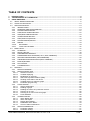
TABLE OF CONTENTS
1.
2.
3.
INTRODUCTION ....................................................................................................................................... 5
THE RECIPIENTS OF THIS MANUAL ..................................................................................................... 6
USING XWEB-EVO ................................................................................................................................... 6
3.1 INITIAL WIZARD PROCEDURE .............................................................................................................. 6
3.2 ACCESS TO THE SYSTEM .................................................................................................................... 13
3.3 XWEB SYSTEM SETUP ........................................................................................................................ 14
3.3.1 INTRODUCTION.......................................................................................................................... 14
3.3.2 HOMEPAGE AND NAVIGATION BAR .......................................................................................... 14
3.3.3 SYSTEM CONFIGURATION.......................................................................................................... 15
3.3.4 CONTROLLER CONFIGURATION ................................................................................................. 16
3.3.5 USER/BOOK CONFIGURATION ................................................................................................... 23
3.3.6 ALARM CONFIGURATION........................................................................................................... 26
3.3.7 STOP/START ACQUISITION ........................................................................................................ 33
3.3.8 SYSTEM VERSION/UPDATE ........................................................................................................ 34
3.3.9 REBOOT ...................................................................................................................................... 34
3.3.10
SHUTDOWN............................................................................................................................ 34
3.3.11
LAYOUT SETUP MODE ............................................................................................................ 35
3.4 MENU TOOLS .................................................................................................................................... 37
3.4.1 SCHEDULER ................................................................................................................................ 37
3.4.2 DEVICE LINE TEST ....................................................................................................................... 49
3.4.3 PERFORMANCE MANAGER ........................................................................................................ 50
3.4.4 COMPRESSOR RACK OPTIMISER (C.R.O., ONLY XWEB5000) ..................................................... 53
3.4.5 DEW POINT MANAGEMENT (SOLO XWEB5000)........................................................................ 58
3.4.6 XWEB5000 SUPERVISOR SYSTEM (ONLY XWEB5000) ............................................................... 61
3.4.7 BACKUP/RESTORE ...................................................................................................................... 69
3.4.8 DAILY EXPORT ............................................................................................................................ 70
3.4.9 CALENDAR SETUP ...................................................................................................................... 71
3.5 DESKTOPS .......................................................................................................................................... 72
3.5.1 DESKTOP OVERVIEW.................................................................................................................. 72
3.5.2 DESKTOP DEVICE VIEW .............................................................................................................. 76
3.5.2.1
3.5.2.2
3.5.2.3
3.5.2.4
3.5.2.5
3.5.2.6
3.5.2.7
3.5.3
CHART DESKTOP ........................................................................................................................ 82
3.5.3.1
3.5.3.2
3.5.3.3
3.5.3.4
3.5.3.5
3.5.3.6
3.5.4
Graph configuration ............................................................................................................ 82
Reading of graph ................................................................................................................ 85
Reading the values of a particular moment ........................................................................ 85
Zooming-in on area............................................................................................................. 86
Zooming-in on area of overview graph ............................................................................... 86
DATA EXPORT .................................................................................................................. 86
ALARMS DESKTOP ...................................................................................................................... 88
3.5.4.1
3.5.4.2
3.5.4.3
3.5.4.4
3.5.4.5
3.5.5
Selection of device .............................................................................................................. 76
Variable displaying .............................................................................................................. 77
Modification of set-point ...................................................................................................... 78
Start Fast Acquisition Modem (FSM) .................................................................................. 79
Sending commands to the device ...................................................................................... 80
Variable section for real time graph .................................................................................... 80
Parameter programming ..................................................................................................... 81
Alarm display filter .............................................................................................................. 88
Alarm List Export ................................................................................................................ 89
Display alarm details ........................................................................................................... 90
Read/Write Alarm Notes ..................................................................................................... 90
Check of Alarm Notifications .............................................................................................. 90
DESKTOP PARAMETERS ............................................................................................................. 91
3.5.5.1
3.5.5.2
Parameter reading .............................................................................................................. 91
Parameter writing ................................................................................................................ 91
1592010880 XWEB3000_5000 EVO OPR GB r1.0 2014.11.28
2/100
3.5.5.3
3.5.5.4
3.5.5.5
3.5.6
4.
5.
6.
Parameter map saving........................................................................................................ 91
Parameter map loading ...................................................................................................... 92
Export PARAMETERS MAP ............................................................................................... 92
DESKTOP SYSTEM LOGS ............................................................................................................. 93
3.5.6.1
SYSTEM LOG EXPORT..................................................................................................... 93
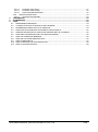
TRADEMARKS ....................................................................................................................................... 94
ACCESSORIES ....................................................................................................................................... 94
FAQS ....................................................................................................................................................... 94
6.1
6.2
6.3
6.4
6.5
6.6
6.7
6.8
6.9
6.10
6.11
MAINTENANCE PROCEDURE ............................................................................................................. 94
I CANNOT ACCESS THE SYSTEM WITH MY PASSWORD .................................................................... 94
MY BROWSER CANNOT REACH THE XWEB-EVO ............................................................................... 94
DISPLAYING OF INCOMPLETE OR INCORRECT PAGES FROM PC ....................................................... 95
SOMEONE HAS RECEIVED A CONFLICTING MESSAGE ON THE IP ADDRESS ..................................... 96
HOW MANY CONTROLLERS CAN THE XWEB-EVO MANAGE............................................................. 96
HOW THE ALARMS ARE MANAGED .................................................................................................. 96
HOW ARE THE ALARM EMAILS RE-SENT ........................................................................................... 96
TABLET COMPATIBILITY .................................................................................................................... 97
HOW TO MANAGE THE JAVA CERTIFICATES ..................................................................................... 98
HOW TO RUN XML READOUT ........................................................................................................... 98
1592010880 XWEB3000_5000 EVO OPR GB r1.0 2014.11.28
3/100
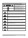
CAUTION: TO PREVENT FLAMES FROM DEVELOPING OR ELECTRIC SHOCK,
AVOID ANY CONTACT BETWEEN THIS DEVICE AND RAIN OR WATER
CAUTION: TO REDUCE THE RISK OF ELECTRIC
SHOCK, DO NOT REMOVE THE COVER IT DOES NOT
CONTAIN ANY PARTS THAT REQUIRE SERVICING BY
THE USER ALWAYS HAVE QUALIFIED STAFF
PERFORM THE PROCEDURES.
THE SYMBOL OF THE LIGHTNING BOLT INSIDE AN
EQUILATERAL TRIANGLE IS USED TO ALERT THE
USER OF THE POTENTIALLY DANGEROUS NONINSULATED ELECTRICAL VOLTAGES
THE SYMBOL OF THE EXCLAMATION MARK INSIDE
AN EQUILATERAL TRIANGLE IS USED TO WARN THE
USER THAT HE/SHE MUST PAY CLOSE ATTENTION
TO THE TOPIC COVERED IN THIS MANUAL
CAUTION
This device must be installed exclusively by service staff with suitable technical
training and experience, who are aware of the dangers that they are exposed to.
The operations described herein are set forth exclusively for the service staff.
CAUTION
Only use modems that are officially supported by this monitoring unit. Dixell srl
cannot be held responsible for any damage caused by the use of non-supported
modems.
CAUTION
Dixell srl reserves the right to amend this manual without prior notice. The latest
available version can be downloaded from the internet site.
CAUTION
The instructions contained in this manual are standard for models “XWEB-EVO
3000” / “XWEB-EVO 5000”. Any particular features are specified expressly.
CAUTION
This control and monitoring unit fulfils EN 12830 for use with probes to detect
measurements referred to in 13485
CAUTION
This is a class A product. It can cause radio-interference in residential
environments. Should this occur, the user should take suitable counter-measures
CAUTION
Dixell srl reserves the right to vary the composition of its products without prior
notice to the customer, ensuring the identical and unchanged features of the same
1592010880 XWEB3000_5000 EVO OPR GB r1.0 2014.11.28
4/100
1.
INTRODUCTION
Congratulations for having purchased this product.
XWEB-EVO represents one of the most advanced monitoring, control and supervision systems available on
the market today. The user will benefit from a power tool, which is easy to use and highly customisable for all
requirements. It uses the most advanced technology for displaying the web pages and is based on the
Linux™ operating system which guarantees its efficiency and reliability. The hardware is based on highly
reliable industrial boards that require practically no maintenance whatsoever.
Its user interface is available both in local and in remote formats. Locally, it can be accessed by connecting
XWEB-EVO to a monitor, mouse and keyboard. In remote, it can be connected to a regular home computer
with an Internet browser, such as Internet Explorer, Google Chrome or Mozilla Firefox.
The user interface is optional once the machine has been configured: the interface devices can be
disconnected or switched off during operation.
XWEB-EVO can be easily installed on a desk or 19" rack. The connectors for connection to the
groups/external accessories (such as screen, network, modem, printers, etc.) are located on its rear.
XWEB-EVO is designed and bases its operation not only on the Dixell network of controllers. Its main
applications are medium/large supermarkets, industrial refrigeration and air conditioning.
In addition to the normal monitoring systems, XWEB-EVO provides (for all models):
- the recording of temperatures in compliance with food hygiene standards (UNI EN 12830, HACCP)
-
the tracking and management of system and control alarms (and centralised management for the
XCenter product)
-
the management of controllers with planned operations
-
the programming of controller parameters
-
and much more
The following tools are added to the XWEB-EVO 5000 models:
- Supervision (SPV). For load control, light control, etc.;
-
Compressor Plant Management (Compressor Rack Optimiser, CRO). To better manage the availability
of cooling power;
-
Anti-Sweat Heater Control (DEWP). Useful for the management of the anti-sweat heaters
These tools are particularly useful for Energy Saving optimisation.
1592010880 XWEB3000_5000 EVO OPR GB r1.0 2014.11.28
5/100
2.
THE RECIPIENTS OF THIS MANUAL
The contents of this manual are intended for professional users, such as the XWEB-EVO installer and/or its
end user. The configuration and usage procedures of the XWEB-EVO are an integral part of this manual.
Users may be professionals such as energy-managers or supermarket directors.
In addition to this manual, we also recommend reading the installation manual provided in paper form, inside
the product package, and in electronic form on the Dixell site, under the "manual" section.
3.
USING XWEB-EVO
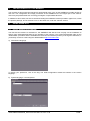
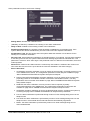
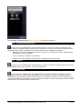
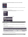
3.1
INITIAL WIZARD PROCEDURE
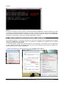
The first time the machine is switched on, the XWEBEVO will ask the user carrying out the installation to
specify some essential parameters for the operating of the machine. The screens listed below make up the
"initial wizard" procedure and are available from the local user interface (monitor) or through the webserver, if
you directly connect to xweb using the default address http://192.168.0.200
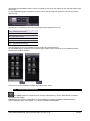
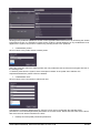
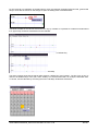
a) Initial wizard language.
To specify your preference, click on the flag. The Initial configuration wizard will continue in the chosen
language.
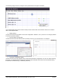
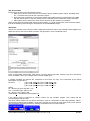
b) System language / Local keyboard
1592010880 XWEB3000_5000 EVO OPR GB r1.0 2014.11.28
6/100
System language. It represents the language that the system uses for the parts that do not refer to a user,
thus to its language. For example, for alarm or system notifications. To specify your preference, select the
language from the list and press "Next". This language is also used for the Admin user.
Local keyboard. Indicate the configuration of the keyboard physically connected to the XWEB. This
configuration is not linked to the configuration of your PC's keyboard. Once you have selected your preferred
parameters, press "Next" to continue with the procedure.
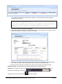
c) System Identification.
These boxes describe the system, displaying both the name and several parameters that can be used to
indicate to the user the references of those in charge of maintenance or servicing of the machine. Once you
have selected your preferred parameters, press "Next" to continue with the procedure.
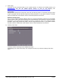
d) Date/time time-zone setup
Configuration parameters of the XWEBEVO time. The time can always be changed by hand; or automatically
synchronised with an NTP time-server with a daily/weekly/monthly interval. We recommend using an NTP
server that is geographically in your vicinity, for example, in your own country. We recommend asking your
network administrator for the name of the NTP server that will be used.
1592010880 XWEB3000_5000 EVO OPR GB r1.0 2014.11.28
7/100
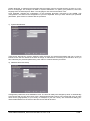
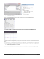
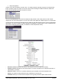
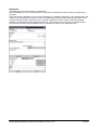
e) Network setup.
For the XWEB network interface configuration. Normally, these parameters are to be agreed with the
network administrator, so it is advisable to contact him/her for guidance and support.
- ‘Lan enable’: disable the check to use the XWEB with local interface only (monitor and keyboard). In this
way, it will not be possible to access the server by means of the local network or internet. Disabling is not
a common procedure: if in doubt, keep this box enabled.
-
‘Automatic DHCP’: enable this box if your network provides a DHCP server and if you want it to inform
the XWEBEVO regarding which IP to use. Disabling implies that the user configuring the XWEBEVO
must explicitly indicate the following parameters:
Hostname
IP Address
IP Mask
Gateway IP Address
DNS1 IP Address
DNS2 IP Address
Domain search name/ip address
-
‘Host name’. Name identifying the machine within the network. Example XWEB0001
-
‘IP Address’: is the unambiguous address used to access XWEB. There are two types of IP addresses:
private and public. The first are used when the clients connected to the network must not be externally
reachable; a closed environment is created where communication is only enabled between the network
PCs. 192.168.x.y is an example of a private address. The public IPs are used when there is need for
visibility on the Internet.
-
‘IP Mask’: is a filter that allows for the routing of the packs directly to clients belonging to the subnet
mask. For example, a subnet mask 255.255.255.0 enables XWEB to directly reach only the PCs with IP
addresses compatible with the mask, with the exception of the last octet. All other requests are routed to
the gateway (if present).
-
‘Gateway IP’: The Gateways are devices that handle the routing of the network traffic that is unable to
directly reach the destination IP. Example 192.168.0.1
-
‘DNS1/DNS2 IP Address’: In order to reach a web server on the internet, you must enter the name, e.g.
www.dixell.com, in the Browser address bar. In fact, following the use of specific communication
protocols required to guarantee the efficiency and the safety of the network, the name is converted into a
number (the IP address). This operation is performed by a DNS server. The ISP or network administrator
can normally provide a DNS server. Example 10.100.1.20
-
‘Domain search name/ip address’. Example MYCOMPANY.COM
1592010880 XWEB3000_5000 EVO OPR GB r1.0 2014.11.28
8/100
-
‘2nd web-server port’: is the network port on which the web server is listening. The default port is number
80. However, for some network needs, it may be necessary to change the default port value (port 81 and
8080 may be the values normally used).
-
‘Enable local DHCP Server’: it makes sense to enable this function only if you do not wish to connect the
XWEB to a network but only to a PC, where the network interface does not specify an IP. If in doubt,
keep this box disabled to avoid network conflicts.
-
‘Enable net speed negotiation’: enables the automatic speed adjustment of the board with the network,
after a link-down event.
f)
Modem setup
XWEB requires a modem to send faxes and, in some cases, to send emails. In the first case, the system
works independently, whilst in the second, it is necessary to configure the dial-up connection (see next
point). Attention: only Dixell-approved modems can be used.
g) Dial-up setup.
The configuration of the dial-up parameters is necessary to establish a connection with the internet
provider via the modem; for sending emails. This is also useful in cases where the XWEBEVO is
connected to the local network via an Ethernet cable yet there is no access to the mail sending server.
The configuration parameters are always supplied by the provider; refer to this documentation.
1592010880 XWEB3000_5000 EVO OPR GB r1.0 2014.11.28
9/100
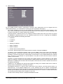
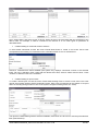
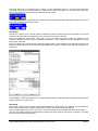
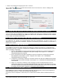
h) Email setup.
The XWEBEVO is able to send emails, generally to notify updates on the status of alarms. To enable
this function, it is necessary to enable the service by completing the configuration. The configuration
parameters can be supplied by your internet provider or by your network administrator.
The XWEBEVO supports different types of authentication protocols:
No authentication
User/Name normal
User/Name TLS (without STARTTLS)
User/Name TLS
User/Name SSL
The TLS protocol is associated with ports 25 and 587; the SSL protocol is normally associated with port
465.
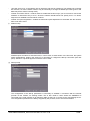
i)
SMS setup.
The XWEB is able to send short text messages via SMS. Two types of services can be used:
via LAN. Visit the following link: http://www.netech.it/ir_smsalert to configure the SMS. After having
completed the online registration form, you will receive an email with an activation code that you
must include in the XWEB configuration.
via GSM. If you have connected a GSM modem to the XWEB, you will be able to use it to send
messages using your phone credit.
1592010880 XWEB3000_5000 EVO OPR GB r1.0 2014.11.28
10/100
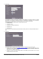
j)
Printer setup
The printer can be connected locally or use a network printer. To obtain a list of tested printers, go to
www.dixell.com and visit the XWEB support section or click on the following link:
http://www.emersonclimate.com/europe/ProductDocuments/DixellLiterature/PrintersXWEB.pdf
Local printer
Once you have selected the local printer, select the port that the printer is connected to through means
of the Local printer list box and then select the correct print driver. If your printer model is not listed,
select the model that is most similar in terms of name and presence from the list.
Windows network printer
Once you have selected Windows Network Printer, the system automatically searches for the available
network printers. After a few minutes (based on the size/complexity of the network), the full list of printers
will appear. If your printer does not appear in the list, it cannot be used; try to repeat the search
procedure. After having selected the printer, select the appropriate print driver. If your printer model is
not listed, select the model that is most similar in terms of name and presence from the list.
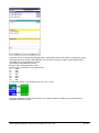
k) Auxiliary output setup
The boxes set the normal logic for the XWEB AUX relays
The disabling of the ‘follow alarm delay’ box energises the relay in sync with the reading of the alarm
status.
1592010880 XWEB3000_5000 EVO OPR GB r1.0 2014.11.28
11/100
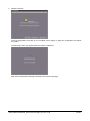
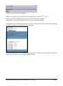
l)
Wizard conclusion
The first configuration procedure is now complete: press "apply" to apply the configuration and reboot
the system.
The following screen may appear while the system is rebooting.
Wait a few minutes after rebooting to be able to access the login page.
1592010880 XWEB3000_5000 EVO OPR GB r1.0 2014.11.28
12/100
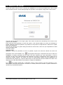
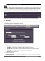
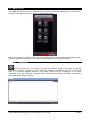
3.2
ACCESS TO THE SYSTEM
Access the system from your PC by entering the XWEBEVO IP in the browser address bar. With a direct
local connection [screen, mouse and keyboard], this operation is not required, simply switch on the screen.
The user will be directed to the "login" page. From which all users will consistently have access to the
system's user interface.
Enter Username and Password to access the system. If the entered details are correct the homepage is
loaded, otherwise repeat the operation. Pay attention to the presence of alphanumeric characters or capital
letters in the password.
You can only connect to a system being accessed for the first time, which has just completed the "initial
wizard" procedure, with:
Username: Admin
Password Admin
Attention: change this password as soon as possible; anyone can read this manual and come into
possession of the access details. Icon
may appear bottom-right. It represents the case in which the
XWEBEVO is already operational and an alarm has been detected (e.g. high temperature). It will be
necessary to login with a valid username and password to be able to recognise the type of alarm and to
analyse the system situation. The alarm icon does not automatically assume that the XWEBEVO has
activated the relay outputs (e.g. to pilot an alarm siren) nor that someone has been notified of the alarm. This
depends on how the administrator has decided to configure the XWEBEVO.
Icon
may appear bottom-left. It represents cases in which access to the user interface by nonadministrator users has been blocked. This block is normally executed to indicate a system maintenance
operation by a specialised operator.
1592010880 XWEB3000_5000 EVO OPR GB r1.0 2014.11.28
13/100
3.3
XWEB SYSTEM SETUP
3.3.1
INTRODUCTION
In its configuration, the XWEB-EVO system requires connection to its interface of Modbus devices. Make
sure that:
1. the controller network is suitably connected paying particular attention to the configuration of the
device addresses, to avoid non-admitted duplications.
2. all instruments are properly powered. Create the list of all connected instruments. Then compare
this list with the number of instruments effectively detected by means of the automatic procedure
The XWEBEVO allows for the management of different device lines (also called "nodes"), which can use
different types of physical connections and configurations for communication. Obtain the network
documentation.
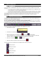
3.3.2
HOMEPAGE AND NAVIGATION BAR
The page that the XWEB-EVO displays on login is the “Desktop Overview”. This is further detailed later in
the manual, in the section relating to Desktops.
The user can also browse the other main pages that are grouped in the DESKTOPS menu of the navigation
bar. Or in other pages, typically for configuration, present in the MENU section.
The navigation bar is always visible on all pages and it enables the user to run the LOGOUT, in other words,
to display the interface on the page requesting the username and password.
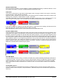
The user is provided with additional information in the navigation bar, such as:
Date and time of system
Information on connected user
State of access block to "non-admin" users.
block active;
block not active.
Click on the padlock icon to activate and deactivate the block: a dialog will appear to confirm the
operation. When the system is blocked an indication appears on the login page.
State of the acquisitions.
State of the alarms. At least one active with icon present
active;
not active
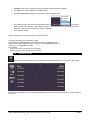
The other pages can be accessed from the navigation bar by clicking on the icons
Desktop Overview
Desktop DeviceView
Desktop Chart
Desktop Parameters
Desktop Alarms
1592010880 XWEB3000_5000 EVO OPR GB r1.0 2014.11.28
14/100
The DESKTOPS and MENU menus can be accessed by clicking on the buttons on the right-hand side of the
same page.
For the DESKTOPS pages, navigation is carried out via the carousel from which the user can choose the
desired page.
Alternatively, it is possible to scroll down the pages using keyboard short-cuts:
ALT-H (Desktop Overview)
ALT-W (Desktop DeviceView)
ALT-G (Desktop Chart)
ALT-P (Desktop Parameters)
ALT-A (Desktop Alarms)
ALT-L (Desktop System logs)
The keyboard short-cuts are available from the local and remote interfaces.
For the MENU pages, navigation is executed through means of the connections in the “XWEB SYSTEM
SETUP” and “TOOLS” sections.
The user can access the desired section by clicking on the name.
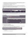
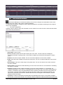
3.3.3
SYSTEM CONFIGURATION
The XWEB system is configured upon machine commissioning, via the "initial wizard" procedure
described in the chapter.
Subsequently, the system configuration can be modified by accessing the MENUXWEB SYSTEM
SETUPSystem Setup. See chapter 3.1 - INITIAL WIZARD PROCEDURE.
1592010880 XWEB3000_5000 EVO OPR GB r1.0 2014.11.28
15/100
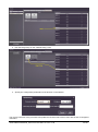
3.3.4
CONTROLLER CONFIGURATION
The controller-device configuration phase allows for the association of each connected device with
the system. For each device, the system will be able to represent and configure its attributes and functions.
The system will, in relation to the selected device, only show the attributes (categories, alarms, inputs, etc..)
typical of the device itself. To be able to modify the faulty configuration parameters, the acquisitions must be
switched off. Should they remain switched on; an error message will appear upon accessing the page:
When entering configuration mode, from this page it will be possible to launch the following operations:
A.
DEVICE FIND
Performs a search of the controller network for the Dixell devices. This procedure is automatically launched
when no device has been configured. This procedure can also be manually run in the next phase when the
tools are already configured, by accessing the tab "Find".
To perform the search for the controller devices (also called "nodes")
1. Specify a protocol.
dixell485: controller search, optimised for wired networks (no wireless)
dixell485xev: controller search, optimised for wired XEV modules (no wireless)
dixell485-icool: controller search, optimised for wireless networks (using the iCOOLL modules)
mb485tcpip: controller search, Modubus-485 connected on tcp/ip gateway
mbtcpip: Modbus search on tcpip
2. Specify the 485 serial line
The XWEB-EVO simultaneously allows for the management of 2 serial lines. Each line can address a
maximum of 247 devices.
1592010880 XWEB3000_5000 EVO OPR GB r1.0 2014.11.28
16/100
3. Specify whether or not the system must run the search by controlling the silence time. The enabling of
this parameter allows for the stopping of the search procedure should noise be detected on the line.
If in doubt as to whether or not to enable this function, disable it.
4. Specify the Modbus range of addresses to be detected
5. Press "Start search" to run the operation.
The search results may display the list of detected devices that can be added to the network configuration.
The presence of the system device library is indicated in the "Library" column with the symbol . The
missing library must be installed should another symbol be displayed.
The name of the device and the group of pertinence can be configured when the row is selected (as shown
below).
To confirm the configuration of the devices, select them and press "Apply".
Attention: from this window it is not possible to replace the set-up of controllers already present in the
configuration. If at least one of the selected addresses is already present in the "Device List", you will receive
an error message:
If you have changed a physical device and need to replace it in the system configuration, you must first
remove it from the device configuration.
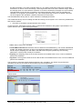
B.
ADD/REMOVE DEVICES, MANUAL SETTING
The association with the instrument network configuration can be manually added or removed to/from the
controller devices by the user. You must access the "Add/Remove Device(s)" tab.
The list of all the libraries in the system is displayed in this window.
Add a device
1. Select the library to be used from the list:
1592010880 XWEB3000_5000 EVO OPR GB r1.0 2014.11.28
17/100
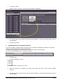
2. Run the Drag’n’Drop on the "Add Device(s)" area:
3. Specify the configuration parameters of the devices on the network.
The correct execution of the procedure will update the left-hand side of the screen with the list of configured
controllers.
1592010880 XWEB3000_5000 EVO OPR GB r1.0 2014.11.28
18/100
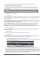
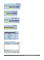
To remove a device
1. Select the device you wish to remove from the network configuration
2. Run a drag’n’drop on the "Remove Device(s)" area. Attention: to correctly execute the drag, click on
the dotted area
3. Confirm the removal
C.
CONFIGURATION OF THE DEVICES-GROUPS
The user can assign controller devices to groups so as to order the configuration according to a functional
diagram or physical positioning within the supermarket.
The separate representation of the groups can be seen in the main "Overview" page.
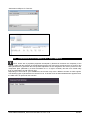
Access the "Group Manager" tab to configure the groups.
To add a group
1. Press the "Add group" (+) key
2. enter the name of the group. E.g. "BT"
3. Select the devices to be added to the group. Keys SHIFT and CTRL can be used for multiple
selection.
4. Run the drag’n’drop of the devices on the group box. Attention: to correctly execute the drag, click on
the dotted area
1592010880 XWEB3000_5000 EVO OPR GB r1.0 2014.11.28
19/100
It is also possible to assign the devices to the groups directly using the "Device Find" procedure.
D.
RESOURCE CONFIGURATION OF DEVICES
It is possible, for the devices already added to the controller network configuration, to customise their
resources. For example, the variable name as well as other features. Select the "Device Resources" tab to
access this feature.
Customisation of device name.
Enable Device
No: by enabling this option, XWEB not query the device and therefore no value from the device is displayed.
This option is useful when you want to create pre-device configurations but will not fit them to keep them in a
real network context.
Yes, not logging in OFF mode: by enabling this option, XWEB interrogates the device. In the event that the
device is in ON displays the data in real time keeping them stored in the historical archives. In periods when
the device is OFF, the device data are not available.
Yes, not logging in OFF mode: by enabling this option, XWEB interrogates the device. Both in the case
that the device is in the ON or OFF displays the data in real time keeping them stored in the historical
archives. This option is useful in case the tool should be used as a 'probe'; the data read from the
instruments in OFF are not always valid and should be checked with Dixell on what tools to use this function.
Main Sampling (mm:ss)
Registration time of main history data. This time represents the maximum resolution of each sample, after
the two days of sampling.
No-Link timeout
Time after which the system detects the condition of the disconnected device.
XWEB Clock-Sync
Enable the XWEB in order to synchronise the instrument clock. This option is only available for devices with
RTC. The update operation is automatically run by the system on a regular basis.
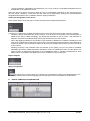
Customisation description of variables and of the unit of measure
1. Select the variable of which you wish to change the description. The string can be edited by typing in
the "Custom name" or "Unit" column.
Registration in threshold main data (Red.Edge) and not sampling (only for digital type variables).
This function allows you to keep the thresholds unaltered, even below the sampling times for the main
data for the variables selected, in order to allow for the detailed graphical representation of the same
variables, even after two days. To enable the function, tick the box relating to the variable in the "Sodsc"
column. Attention: the enabling of this function can also drastically reduce the overall memory of the
XWEB history. Only enable this function for short periods of a few days.
1592010880 XWEB3000_5000 EVO OPR GB r1.0 2014.11.28
20/100
Enabling of the variable for "DeviceView" page.
The variable is inserted in the DeviceView page if the box corresponding to the same variable is
enabled. By default, each variable is enabled in this context.
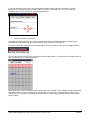
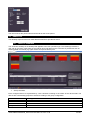
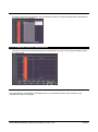
Enabling of the Notify variable
The variable is inserted in the snapshot table, in the instrument notifications. For example, as seen in the
image below, the variable is inserted in "Row 3" of the table. All values in this table are relative to those
displayed when the notification is sent.
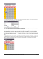
Enabling of the Graph variable
The variable is inserted in the snapshot graph, in the instrument notifications. For example, as seen in the
image below, the variable is inserted in ''Row 4'' of the graph.
Clone configuration of an instrument
The XWEB-EVO allows for the cloning of the configuration of a device to reduce the number of configuration
operations on the network instruments. To do this, select the source control and click on "Clone Settings".
From the drop-down menu select:
- “Everything”: applicable only to compatible instruments. For a copy of all device parameters.
1592010880 XWEB3000_5000 EVO OPR GB r1.0 2014.11.28
21/100
-
“Common Settings”: applicable to all instruments. For a copy of only the compatible parameters that can
be detected on the destination device.
Select the devices to which you wish to apply the copy of configuration parameters on the network and click
OK. The ‘name’, ‘sampling’, ‘no-link time out’ and ‘clock syncro’ parameters, at this point, are all duplicated
alongside all descriptions of the variables and their display parameters.
Advanced configuration of the device
Press “Switch Mode” at the top-right to access the advanced configuration parameters
The user can configure the variable description (resources) of the device and for each of these, configure:
- Sampling: specific acquisition time of the resource. If set at 00:00, the acquisition time will that which is
global for the device ("Main Sampling"). By default this parameter is set at “00:00”. This parameter is
relative to all resources available being read by the device and not for the controls.
-
Save: data-logging enabling for the variable. If this checkbox is disabled, the variable is displayed in real
time on the runtime/device-view page but the history of its trend will not be maintained. This parameter is
enabled by default. This parameter is relative to all resources available being read by the device and not
to the controls.
-
Reading Frequency: this parameter sets the activities on the polling cycle for the resource. Disabled
debilitates all resource reading and writing operations; each X to enable them where X is the delay in the
polling rounds. By default this parameter is set to Disabled or Each 1 (variable management for each
polling round, for analogue and digital resources) or Enabled for control resources.
Export template
Apply configuration
The Apply key is used to apply any changes to the configuration made on the Web-Browser to the
XWEB-EVO system. We recommend applying the configuration to even the smallest of modifications.
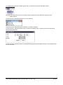
E.
DEVICE TEMPLATE CONFIGURATION
1592010880 XWEB3000_5000 EVO OPR GB r1.0 2014.11.28
22/100
The configuration of a device can be imported into the Template gallery. These devices can then be setup
using the “Add/Remove Devices” section as demonstrated in the image below
3.3.5
USER/BOOK CONFIGURATION
The user configuration page allows for the configuring of the XWEB-EVO book. This book is unified
in the system for all operations involving external users. Users are intended, for example, as those who have
access to the web interface; users can also be those receiving alarm notifications.
Upon the system commissioning, there will be a single user configured and enabled: Admin. For which full
access to the Web interface in English is guaranteed. The user belongs to the "superadmin" profile.
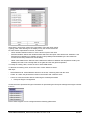
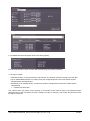
The user with right to access this page can:
Display/modify the access rights of users
Clicking on the user list updates the section on the right-hand side of the screen with the "User Details" and
"User Permissions". To apply the changes to these system sections, press "Save" on the "Users" section. To
delete users, select the desired user and press "Delete". Attention: it is not possible to delete the
‘superadmin’ profile user; Attention; the user permissions may differ from those set on the profile indicated
for the same user: the profile name is that of default which was used to create the user.
Display/modify the profile rights
1592010880 XWEB3000_5000 EVO OPR GB r1.0 2014.11.28
23/100
Clicking on the profile list updates the section on the right-hand side of the screen. By accessing the "Profile
Permissions" section, it is possible to browse and/or modify the profile attributes. for any modifications to be
applied to the system, they must be confirmed by pressing "Save" in the profile list.
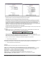
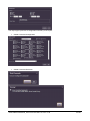
Create/Delete profiles
Click on "New" in the profile section to add a profile.
Name the profile and select the starting profile: the new profile will have the same access rights as those of
the starting profile.
To delete a profile from the system, select it and press "Delete" in the profile area. Attention: the
superadmin/admin/user profiles cannot be deleted.
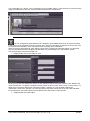
Create/Delete users
Click on "New" in the user section to add a new user.
Complete the compulsory data and press "Confirm". Each user is created with the selected profile
permissions. The username/password parameters are for web access. Name and Last name are the terms
with which the user will be indicated in the book.
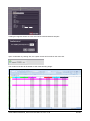
Desktop and user/profile permission parameters
1592010880 XWEB3000_5000 EVO OPR GB r1.0 2014.11.28
24/100
The user permissions enable him/her to perform a number of operations.
Access to the desktops is configured in the Desktop section and the main desktop that is accessed
immediately after login is set.
1592010880 XWEB3000_5000 EVO OPR GB r1.0 2014.11.28
25/100
3.3.6
ALARM CONFIGURATION
The alarm configuration is accessed from the MENUXWEB SYSTEM SETUPAlarms
Management. Access to the page allows for the customisation of the alarm categories and notification
parameters: The XWEB-EVO uses this information to detect the alarms from the controllers and notify their
status to the users in the book.
Principles of operation
The XWEB-EVO detects the present controller alarms in an alarm-category. Once the device alarm has been
detected, the system confirms this after a certain period of time (see Delay parameter, "alarm category
parameters"). Upon alarm confirmation, the first level users are also notified. If the alarm persists, other
notifications may be sent to the same recipients (see re-send time, "alarm level parameters"). If the alarm
persists beyond the maximum time permitted to the level (see re-send life time, level parameters), the level
shifts, sending the subsequent notifications to the recipients of the subsequent level. The alarm recovery is
also normally notified: there are many parameters that can be used to customise notifications according to
your requirements; these will be individually described in the following pages.
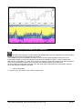
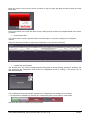
Above, an example of alarm notification with a PDF file, included as an attachment in the new alarm
notification mail.
1592010880 XWEB3000_5000 EVO OPR GB r1.0 2014.11.28
26/100
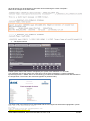
List of controllers
The list of configured controllers is always present on the left-hand side of the screen. Clicking on the lens as demonstrated below - selects the "Category Settings" tab which displays the list of all variables configured
as alarms.
The buttons are also present on the left-hand side of the window.
1. “Clone Alarm Settings” for copying between instruments of the same alarm-category settings.
2. “Save Configuration” to apply any modifications. Attention: the save operation must be performed
each time the tab is changed otherwise any modifications will be lost.
On the right-hand side of the window are three different tabs identifying the below described configuration
parameters.
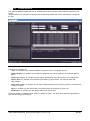
Alarm-Category Parameters Tab
The Alarm-Categories is a list of types of alarm, with the purpose of grouping the alarms that must be dealt
with in the same manner, from a point of view concerning alarm detection and their notification.
For example, it is possible to create a category named "Temperature Alarms" or "Pressure Alarms"; and
associate all alarms of this type with the above-mentioned alarm-categories.
Access the tab in order to scroll down the list of configured alarm-categories. Each alarm-category displays a
list of notification levels (as demonstrated above).
-
press "+" to add a new category.
-
modify the category by pressing
-
eliminate the category by pressing
-
to display the configured alarms for the category, press
1592010880 XWEB3000_5000 EVO OPR GB r1.0 2014.11.28
27/100
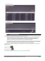
Category parameters:
-
Name: identifies the category itself;
-
Delay: stand-by time for the processing of the alarm, from when it is read by the controller network to
when it is effectively considered an alarm: if the alarm is resolved before this time runs out, the source of
the alarm is ignored. This parameter is useful for the delayed management of the "open door" status
which comes from an I/O board: the variable is not an alarm but with the XWEB-EVO it can be used as if
it were.
-
Accumulation time to alarm reset: the system sends notification when the alarm is reset. However, the
system waits for the resetting of other alarms for the period indicated in this parameter, before sending a
cumulative notification. This therefore reduces the notification line's task; relieving it of any critical
conditions such as is the case when the line is slow (e.g. fax line). This parameter works similarly to the
"Accumulation" time present amongst the "alarm notification parameters": However, in the case of the
alarm-categories, the time is divided between all of the "Alarm Level Settings";
-
Alarm-Level Settings: notification level. The order is important: the first level to be notified (entry level)
is that with the lowest number (“Setting 1”). The up-scaling of the notification level occurs based on the
parameters set in "Settings".
-
Alarm types, quick configuration (optional): list of all types of alarms recognisable in the configured
devices. The sole selection of the types does not change the alarm-category configuration. But on the
contrary, prepares the category for the receipt of these alarms the next time the User assigns a device to
the same category. Example: having configured the category with a "High Temperature" alarm, drag a
list of controllers and drop into the same category: this assigns the "High Temperature" alarm for all
devices in the list for the category.
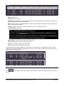
Level Parameter Tab
The alarm notification parameters identify the notification levels. Each level includes the users who receive
the alarm notifications.
-
press "+" to add a new level
-
to modify the level parameters press
-
to eliminate the level press
1592010880 XWEB3000_5000 EVO OPR GB r1.0 2014.11.28
28/100
Some parameters must be set for each "Setting":
-
Setting Name: identifies the notification level
-
{166Notify on Start167}: enabled for the sending of new alarm notifications
-
Notify on End: enabled for the sending of alarm-over notifications
-
Send Single Notification: the enabling of this parameter invalidates the accumulation time. If the
system detects two alarms simultaneously, the users will receive two separate notifications.
-
Accumulation Time: the time during which the system awaits the detection of new alarms for the
sending of a cumulative notification
-
Re-send Time: interval between notifications of persisting alarms. For example, if a new alarm message
is sent but ignored or lost, the system notifies the same message again after the indicated time. This
parameter is critical to "level" climb logic: if this parameter value is 0 after the first notification, the level is
scaled upwards
-
Resend TTL: maximum time within which the continuously active alarm is notified of the current level
rules. After this time, the level is up-scaled to the next level indicated in the alarm-category.
-
Service Activation:
1. AUX2/AUX3: the alarm notification occurs by means of the local relay, physically present on rear
of the XWEB-EVO machine. The configuration parameters of this relay are available on page
“MenuXWEB SYSTEM SETUPSystem SetupAUX Outputs”
2. RAUX1/ RAUX2/ RAUX3/RAUX4: the alarm notification occurs by means of the remote relay
physically present on an XJR40D controller connected to the Modbus network. The relay
parameters of this controller are available on page “MenuXWEB SYSTEM SETUPSystem
SetupAUX Outputs”
3. PRINTER: the alarm notification occurs by means of the local printer physically
connected/configured to the XWEB-EVO. The configuration parameters of this printer are
available on page “MenuXWEB SYSTEM SETUPSystem SetupPrinters”
4. XCENTER: the alarm notification is sent to the Dixell XCenter system. Configure the system by
accessing the page “MenuXWEB SYSTEM SETUPSystem SetupXCenter”
5. FAX: the alarm notification is performed through means of a fax message being sent over the
telephone line
6. FAX OCR: the alarm notification is performed by means of a fax message being sent over the
telephone line in a fixed-width font format and therefore automatically segmented
7. EMAIL: the alarm notification is performed by means of an email message being sent as
demonstrated below
1592010880 XWEB3000_5000 EVO OPR GB r1.0 2014.11.28
29/100
The HTML part is the format rendered by the browser. The text is better suited to automatic
parser and is as follows.
Content-Type: text/plain; charset="UTF-8"
Content-Transfer-Encoding: 8bit
Alarm Report: XWEBEVO Xweb EVO system name|XWEB EVO system description
START|18/10/2013 17:26|RS1-007 New_XR170Cxxxxx|Low Value Pb1
The text is common to all other email formats.
8. EMAIL IMG: the alarm notification is performed by means of the sending of a message, in which
the body constitutes an image. The format is as follows:
9. EMAIL ATT: the alarm notification is performed by means of the sending of an email message
with a PDF file attached and containing the same information as the EMAIL IMG.
10. SMS: the alarm notification is performed by means of the sending of an SMS message.
-
Email/Fax header: customised text entered in the subject field of emails and faxes.
-
Calendar: filter calendar on alarm notifications; the calendar identifies the period during which the
notification messages will not be issued
calendars are set on the system with
. The
present in TOOLS.
1592010880 XWEB3000_5000 EVO OPR GB r1.0 2014.11.28
30/100
All email formats can be analysed by automatic robots examining the section "text/plain".
Below is an example of an alarm email:
Tab System Alarms
Enable system alarms that must be managed by the system, with notification i.e. via email.
The messages sent by the system are of the same type as those managed by "system messages"
By selecting “Email” + “EMAIL INFO” for the sending, you select the extended email format demonstrated in
the image below. The email in the mail client appears as (Outlook 2007):
The same email in text format can be segmented and the most significant information highlighted in yellow:
Date: Tue, 1 Oct 2013 15:38:58 +0000
To: <xyz>
From: Xweb EVO system name <[email protected]>
Subject: Caution: Cpu HT / Stp
1592010880 XWEB3000_5000 EVO OPR GB r1.0 2014.11.28
31/100
MIME-Version: 1.0
Content-Type: multipart/alternative; boundary="---------EVO40DFF36D5A44ECBC"
Return-Path: [email protected]
X-OriginalArrivalTime: 01 Oct 2013 15:38:57.0073 (UTC) FILETIME=[5774E210:01CEBEBC]
-----------EVO40DFF36D5A44ECBC
Content-Type: text/plain; charset="utf8"
Content-Transfer-Encoding: 8bit
IP:10.100.81.208
GATEWAY:10.100.81.1
EXTERNAL-IP:10.100.81.208
DNS1:10.100.80.20
DNS2:
-----------EVO40DFF36D5A44ECBC
Diminutives errors, of subject
Acq OFF
The acquisitions are stopped.
Cpu HT
High temperature of CPU
Ist LS
History disc space almost exhausted
Log LS
Log disc space almost exhausted
Tmp LS
Temporary disc space almost exhausted.
Eml
Email sending errors
Fax
Fax sending errors
Sms
SMS sending errors
Prn
Print errors
Trap
Trap to xcenter sending errors
Di1
Error from digital input 1
Di2
Error from digital input 2
BlackOut
Return from blackout error
Stp
Evo configuration error.
Other information
IP:
GATEWAY:
EXTERNAL-IP:
DNS1:
DNS2:
=>
=>
=>
=>
=>
IP address.
Network gateway address.
(coincides with EVO IP)
First dns
Second dns
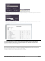
Tab Reports
This window enables the User to verify the alarm configuration from certain reports. Select the filter
identifying the report and press "Apply Filter".
-
Device alarm list, not associated with any alarm-categories
1592010880 XWEB3000_5000 EVO OPR GB r1.0 2014.11.28
32/100
-
List of alarms for User
-
Full configuration
3.3.7
STOP/START ACQUISITION
The XWEB-EVO principally identifies two mutually exclusive statuses:
1. Acquisitions stopped. This status allows for the configuration of the basic machine parameters. For
example, it provides the user with the necessary access to configure parameters relative to the
system or to the controller network configuration. This status does not allow for monitoring or
supervision. Therefore, the controller alarms cannot be detected and notified.
2. Acquisitions active. This status enables the configured machine to establish constant communication
with the instrument network and, consequently, allows for monitoring and supervision. Attention: this
status must be enabled at the end of the machine's configuration by the installer.
The status of the acquisitions is displayed on the navigation bar, so it can be identified by the user on each
XWEB-EVO page.
Acquisitions active:
Acquisitions inactive:
Access MENUACQUISITIONSStart Acquisition to start the acquisitions
1592010880 XWEB3000_5000 EVO OPR GB r1.0 2014.11.28
33/100
Access MENUACQUISITIONS Stop Acquisition to stop the acquisitions.
3.3.8
SYSTEM VERSION/UPDATE
Access the menu “XWEB System SetupSystem Update” to access the update control panel. This
window displays all updates already applied, and it is possible to check if there are further updates present.
Depending on the system configuration, there will be three keys for installing new updates:
Repository. For remote installation via internet connection. As configured in section “XWEB System
SetupSystem SetupUpdates”.
Usb. For local patch installation via USB key.
Upload. For remote installation with uploading of update file from web-browser
3.3.9
REBOOT
Access the menu “XWEB System SetupReboot” to reboot the machine software. Rebooting is useful
to qualified personnel only, such as the customer support team.
3.3.10 SHUTDOWN
Access the menu “XWEB System SetupShutdown” for machine shutdown. Shut down is useful to
qualified personnel only. !!Attention!! This operation is not reversible, so when the machine has been
switched off, it will not switch on again until the machine is powered or the switch-on button is pressed. We
recommend disabling this operation for users accessing the system remotely. Rebooting is useful to qualified
personnel only, such as the customer support team.
1592010880 XWEB3000_5000 EVO OPR GB r1.0 2014.11.28
34/100
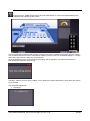
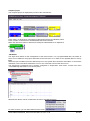
3.3.11 LAYOUT SETUP MODE
Access the menu “XWEB System SetupLayout Setup Mode” to create customised desktops with
graphic widgets made available by the system.
The user populates the desktop with widgets via drag’n’drop from the palette accessed by pressing "Menu".
The procedure requires the user to hold down the left key of the mouse over the desired widget, i.e. "image",
and to then drag it onto the work area for positioning.
Once the widget is in place, proceed with dimensioning and configuration. The latter must always be
performed by pressing the "wrench" key.
The page - different for each type of widget - which defines the subject parameters, opens when the wrench
key is pressed.
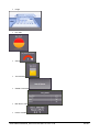
The supported widgets are:
Rectangle
1592010880 XWEB3000_5000 EVO OPR GB r1.0 2014.11.28
35/100
Image
Pie chart
Gauge
Thermometer
Global Commands
Mini Device View
Device Variable
1592010880 XWEB3000_5000 EVO OPR GB r1.0 2014.11.28
36/100
3.4
MENU TOOLS
The XWEB-EVO allows for the use of different tools for device programmatic management. To access these
tool pages, open MENU and select TOOLS as demonstrated below.
Many of the functions in this menu require the use of a virtual machine JAVA. Refer to the last pages of this
manual for certificate management ( “6.10 HOW TO MANAGE THE JAVA CERTIFICATES” ).
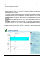
3.4.1
SCHEDULER
With this powerful tool, it is possible to quickly and efficiently manage the sending of repetitive
commands to the tools. Commands are, for example, the sending of commands to switch on or to switch off
lights or to schedule periodical defrosting. The graphic display aids the management of the single
commands. To run the "Scheduler" access the menu "TOOLS" and then press "Scheduler". The following
window will appear (JVM is required):
1592010880 XWEB3000_5000 EVO OPR GB r1.0 2014.11.28
37/100
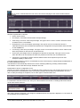
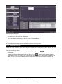
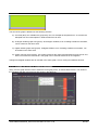
The following image shows an example of the operational and configured scheduler
The complete daily range (from 00:00 to 24:00) is shown at the base of the window. Each hour is marked
with a vertical placeholder.
Setting saving
Access the menu item FileSave to save the configuration. Attention, once you save it is no longer possible
to recover a previous version.
Print scheduler configuration
Access the menu item FilePrint to launch printing in local on your web-browser. For example:
Scheduler configuration export
Access the menu item FileExport to file to export the Scheduler configuration in a TXT file. When selecting
this menu, you will be asked to indicate the path and name of the file to be saved. We recommend saving
the file with .txt extension (e.g. “scheduler_xweb.txt”).
1592010880 XWEB3000_5000 EVO OPR GB r1.0 2014.11.28
38/100
SCHEDULER Enabling
For the unconditional enabling of the scheduler, access the menu FileScheduler Enabled.
To completely disable the scheduler, access the menu File and untick any item enabling the same
scheduler.
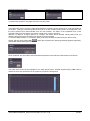
A disabled scheduler is recognised by the grey class name and the "x" above the events, as demonstrated
above.
The scheduler may also be enabled and disabled from a digital input. The enabling/disabling logic is set by
ticking one of the items of “Enable Scheduler via DI X Y” where X can be 1 or 2 and Y can be Open/Close.
Creation/setting of classes for the events
Access the menu ClassCreate to create new classes or ClassEdit to modify those already existing.
1592010880 XWEB3000_5000 EVO OPR GB r1.0 2014.11.28
39/100
Fill in "Class Name" and select a type of device. Select all tools to be associated with the operations of the
device class. For example, to send a command to the devices or to run other types of operations as
described below.
Creation/setting of command events to devices
To send timed commands, access the menu EventsAdd Event to create a new event. Each event
corresponds to the sending of a command on the controller network to one or more devices.
Choose a command from those available (the system only displays commands common to all selected
tools). Fill in the "Activation Time" value with the desired send time, select a marker and its colour. Press
"Confirm" to add this event to the scheduler.
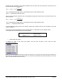
Creation/setting of report events
To create a timed report, access the menu EventsAdd Printing Event to create a new event. The event
reports are normally used as HACCP automatic reports. Each event corresponds to the creation of a report
and to its sending through means of one of the system configured media (printer, fax, email).
The report is created starting with the selected variables; select them one at a time or use the quick selection
filter (Fast Selection).
1592010880 XWEB3000_5000 EVO OPR GB r1.0 2014.11.28
40/100
Activation Time: time the report is created.
Marker colour: marker colour of the event on the scheduler (only for printer
/
).
Add Event to All Days: assignment of the event to all days created in the calendar.
Printout Name: name of report used in the header (only for real time report/print).
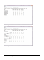
There are two types of created report: real time or archive. The first takes a "photo" of the situation regarding
the tools at a certain time. As illustrated in the image below.
The second takes a "photo" of the situation regarding the tools from the time of the event and up to 48 hours
prior its occurrence. We can have two types of representation:
1592010880 XWEB3000_5000 EVO OPR GB r1.0 2014.11.28
41/100
Not-extended:
This format represents each device with a variable per controller
This format represents each device with multiple variables per controller
1592010880 XWEB3000_5000 EVO OPR GB r1.0 2014.11.28
42/100
Extended: refers to the representation of data with one column per variable. When reading the data
in the column, refer to the number in the header list which identifies the variable.
“Print copies” to print on local printer, configured on xweb.
FAX for sending the report via fax configured on xweb.
Email for forwarding via email, with report in email or as attachment.
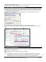
Creation/setting of system message events
To send system messages, access the menu EventAdd System Event. The system events live connected
solely to class “XWEB System Events”, which cannot be removed.
The system events are issued to the recipients and media configured in EventSystem Event Configuration.
1592010880 XWEB3000_5000 EVO OPR GB r1.0 2014.11.28
43/100
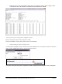
Creating/setting of events generating historical data Excel files
The XWEB-EVO is able to create historical data excel files. There is a 48 hour limit from when the event first
occurred. To configure this option, access the menu EventAdd Export Event.
Select the class on which to connect to the event.
Select the variables for the report.
Select the time for the execution of the event
Set the server parameters on which to create the Excel file containing the report data:
The protocols available are: FTP/SFTP/SCP. A password is required to connect to the server receiving the
Excel files. For the correct "server", "port" settings, etc., we recommend seeking support from your network
administrator. The Server-Address must be a valid IP. The Server-Path must be a valid path, alphanumeric,
delimited with "/" (e.g.: “myPath/mySubPath”). The path on which to create the file must exist. If the path
does not exist, XWEB will attempt to create it, but the directory creation command must be enabled on the
receiving Server-Address for the selected protocol. The Branch-Code must be an alphanumeric string. The
event confirmation will create the event on the selected class, visible with the symbol
1592010880 XWEB3000_5000 EVO OPR GB r1.0 2014.11.28
.
44/100
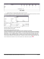
Once configured, the Excel files will be created as: <PATH>/<BRANCH>-<datetime>.XLS as per screenshot
below.
The format of the files is as demonstrated below, where each Excel worksheet is dedicated to a single
device.
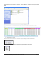
Change/deletion of events
Click on the event: the list of all events at that time configured will open, as demonstrated below.
Once the event is selected, the list of possible actions appears, as demonstrated below.
1592010880 XWEB3000_5000 EVO OPR GB r1.0 2014.11.28
45/100
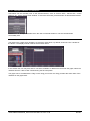
If you click and hold on an event, it is also possible to perform vertical class movements for a display
adjustment or movements on the time axis of the event itself. In the latter case, you can see the new
"Activation Time" on the applet title, as demonstrated below.
Using the calendar in scheduler
By default, for all calendar days, the system uses the "type of day" (Default Day). When configuring the
scheduler for the first time, this day is that proposed by the system for configuration.
The type of day being configured can be recognised by the name positioned high up on the applet title bar.
You can gain access from the menu “Edit DaysCalendar Association” to check that it is associated with all
days: the ‘default day’ is coloured light grey.
Other types of days can be created and then associated on the calendar. The scheduler will then perform the
associated events, for the associated days. For example, you may have configured special events for the
weekend and your calendar may appear as illustrated below, with the (type of) weekend day associated for
public holidays.
1592010880 XWEB3000_5000 EVO OPR GB r1.0 2014.11.28
46/100
To create a new (type of) day, access the menu “Edit DaysNew day definition”. The system requests the
configuration of the following image window parameters
It is necessary to indicate the name of the (type of) day, e.g. "weekend", and give it a colour for recognition.
The colour will be important for visual recognition on the calendar.
The "Enabled" parameter indicates whether the events configured on the day are active. The "Yearly"
parameter indicates whether the day is to be associated - to all years - for operations of association to
calendar. Attention: once the day has been created, the "Yearly" parameter can no longer be modified.
To modify the existing day types, select the day to be modified from the menu Daysand then access the
menu “Edit DaysModify Current Day...”. To delete the current day, access the menu “Edit DaysDelete
Day”.
To associate the days on the calendar, access the menu “Edit DaysCalendar Association”. To associate
the days, click on the day and select the (type of) day desired. It is also possible to associate the (type of)
day on week days by clicking the name in the red band, e.g. apply the day "weekend" to all Sundays.
1592010880 XWEB3000_5000 EVO OPR GB r1.0 2014.11.28
47/100
To configure the previously created (type of) day, access the menu Days and select the day.
Note that the classes are common to all types of day. But that each day defines its specific events.
Display options
Access the menu “WindowsShow Key” to show the key
Access the menu “WindowsShow Calendar” to show the calendar.
Access the menu “WindowsShow Logs” to show the scheduler logs, for the list of sent commands and
other actions performed.
Access the menu “WindowsShow Commands/Printing/System Events/Export Events” to show/hide events
for the current day.
1592010880 XWEB3000_5000 EVO OPR GB r1.0 2014.11.28
48/100
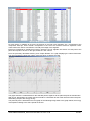
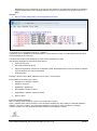
3.4.2
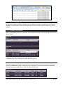
DEVICE LINE TEST
Click on menu “TOOLSDevices Line Test” to access the test page of the communication with the
setup devices.
Access to the window shows the statistics table on the communication with the configured tools. Each device
has been represented in columns:
Device: device name
Success(%): successful communication total percentage
Time Out(%): errors for Time Out percentage. This type of error occurs in cases in which the device
is switched off or not reachable
Exception(%): errors for exception percentage. This type of error occurs when the device is
reachable, but there are inconsistencies between the configuration of its parameters and that shown
on the XWEB-EVO
Crc-Error(%): CRC error percentage. This type of error occurs when the device can be reached, but
there are problems on the line such as interferences.
Overrun(%): percentage errors for packages in transit but not expected. This type of error occurs
when the device can be reached, but there are problems on the line such as interferences.
Unknown(%): percentage of others detected, different from those reported in previous rows.
Example: equality or other errors.
The table enables sorting by column. It is advisable to press "Success(%)" to easily identify the addresses of
the most problematic devices.
The table does not automatically refresh but it can be manually updated by pressing "Reload media".
The statistics can be reset with the keys "Selected" and "All".
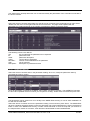
Identification of device configuration errors:
Should a tool show exception errors, it is possible to ask the system to run a new specific test for the tool, so
that it detects the most problematic sizes. The following example demonstrates the identification of a tool
with a certain percentage of exceptions, but no other type of communication error:
It is selected to execute the test. The "test cycle" value identifies the number of readings that will be carried
out for each device resource.
After having pressed "Start test", the configured variable that does not respond is displayed, i.e. Pb3 which is
not enabled by the tool parameters.
1592010880 XWEB3000_5000 EVO OPR GB r1.0 2014.11.28
49/100
3.4.3
PERFORMANCE MANAGER
Performance Manager (or Performance Meter) is a tool for the analysis and verification of the correct
dimensioning of the plant, utility control, operating statistics.
To execute this procedure, configure a device class and finalise the calculation indicating the time range on
which it is to be applied.
Tool class configuration
Create the device class for which the calculation is to be carried out: access the menu “ClassCreate Class”
and indicate the parameters of:
-
Class name: name of class
-
Devices of class: enable devices that must be part of the class. The list of devices is displayed
according to the filter "Typology Filter", which helps to display only the devices belonging to a certain
group.
-
SetPoint: select the set-point variable. The unit of measure depends on the chosen variable.
-
Probe: select the probe variable connected to the set-point. The unit of measure depends on the chosen
variable.
-
Normal Range: select the normal range of the probe value. The unit of measure is the same as that of
the probe variable.
-
Defrost Offset: select the time after defrosting, for which the Probe value is not considered in calculating
the %Cool. In minutes
-
Sampling: sampling period of data requested by the server during calculation. If, for example, you
configure sampling at 1 hour (60 min), requesting data from the last 2 days, the system sends 48 pieces
of "data" (1 sample per hour). As this parameter value increases, the data to be sent by the system will
be reduced. This is the ideal condition for using this tool with a slow or busy telephone network. The
value of this parameter is used as the 'default' value and can be changed in the calculation (window
PerformanceView Class)
-
Avg.Factor: number of transactions represented for the samples sent to server. The system averages
this number of consecutive samples. For example, with the 48 pieces of data returned by the server as in
1592010880 XWEB3000_5000 EVO OPR GB r1.0 2014.11.28
50/100
the above example, if you were to set this value at 1: at a graphic level there will be up to 48 possible
transactions of various colours low/ok/high, assuming that the data is all within a different range. While, if
the average value is 4, there will be a maximum of 12 colour transactions (averages at 4 hours of data).
This parameter has the function of avoiding out-of-range temporary values, which do not affect the
calculation or the graphic representation. The value of this parameter is used as a "default" value and
can be changed in the calculation (window PerformanceView Class)
The Select/Deselect All keys are for a quick selection of all displayed devices.
The Create/Cancel keys are for creating the class and saving it in the system. Or to cancel any modifications
and close the window.
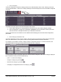
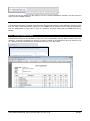
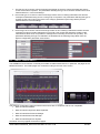
Execution of calculation and presentation of the result
Access the menu “PerformanceView Class” to perform the calculations with graphic representation. The
system asks the user to define some parameters:
-
Class: class of tools to be calculated
-
Circular/Main Data Interval: select the source of data from the XWEB history. The circular data defined
as data, the sampling frequency of which is the highest possible for the system, is limited in time to the
last two days of sampling; the main data is that which has a frequency defined by the recording
parameter in "device setup" usually at 15 minutes.
-
Sampling: the Sampling value set in the class is taken as the default value. Here, it can be modified to
perform the calculation
-
Avg.Factor. The Avg.factor value set in the class is taken as the default value. Here, it can be modified to
perform the calculation
The Cancel key closes the window without performing any calculation. The "Show" key performs the
calculation and shows the results as demonstrated by the example below:
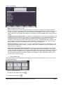
Various clicks
1592010880 XWEB3000_5000 EVO OPR GB r1.0 2014.11.28
51/100
“PerformanceData ScreenShot”
1592010880 XWEB3000_5000 EVO OPR GB r1.0 2014.11.28
52/100
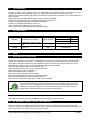
“PerformanceExport To Text File”
3.4.4
COMPRESSOR RACK OPTIMISER (C.R.O., ONLY XWEB5000)
C.R.O. works with a proprietary algorithm developed by Dixell that combines the complexity of the
cooling system with the simplicity of the parameters that the user must set at a program level. It works on two
basic parameters to guarantee the best possible adjustment of the refrigerator: the suction pressure of the
compressor plant (detected by a series XC1000D ver.1.1 or higher controller) and the more critical utility
from a "consumption of cold" point of view.
Depending on the model of your XWEB-EVO, the function may have a different number of CRO engines.
The following types of parameters are common for all. A window such as that illustrated below appears when
the CRO menu is opened for the first time.
1592010880 XWEB3000_5000 EVO OPR GB r1.0 2014.11.28
53/100
Utility Configuration
Create a new class of utilities to use the C.R.O.. The data required to operate the project is extracted from
these controllers. Open the "Class" menu and create a class including the utilities of interest. Utilities are
those with the saturation pressure set-point in common.
Use the Create/Edit/Delete menu items to modify the utility classes. Each utility class can and must be
assigned to one of the CRO engines. The use of the same class applied to multiple engines is not permitted.
Access the menu OperationParameters Engine relative to the desired CRO engine to set the configuration
parameters. The C.R.O. module, to better manage the availability of cooling power, in time, modifies the setpoint of the compressor plant (typically, for utilities in normal temperature mode).
-
Execution interval: indicates how often a new set-point is sent to the plant (in minutes).
-
Analysis interval: indicates for how many minutes, in reverse, the data is to be analysed (operation of
class utilities; in minutes).
-
Reference class: is the set of controllers affected by the calculation of the worst possible case.
-
Device: is the plant controller affected by the modification of the set-point.
-
Set-Point: allows you to select which set-point to use: typically, that of the plant suction section.
1592010880 XWEB3000_5000 EVO OPR GB r1.0 2014.11.28
54/100
-
Worst case threshold: allows for the defining of the intervention threshold for the C.R.P. algorithm (in
%)
-
Neutral zone: specifies an oscillation band (centred on the percentage of the worst possible case) inside
which the algorithm does not intervene.
-
Initial value: initial set-point value. The value can be an estimate: in time, the set-point value sent to the
plant will change -according to the algorithm (typically in °C).
-
Min. and Max. Set-points: safety limit values associated with the minimum and maximum suction
pressure: to prevent C.R.O. from excessively increasing or lowering the pressure to avoid the safety
devices from triggering. (typically in °C). It is good for the minimum value to be as high as possible in
order to optimise energy consumption.
-
Release and Call Gain: the call and release gain are two parameters that decide by how much the
current set-point must be increased/decreased. The call-gain parameter is used should the set-point
need to be decreased. It is useful to set a higher call-gain value than the release-gain in order to quickly
decrease the temperature (typically in m°C/%).
-
Post Defrost Time out: the duration after a defrosting event that is ignored in calculating the percentage
(in minutes).
-
Simulation Mode: The enabling of simulation mode does not send the set-point values calculated by the
algorithm
-
Cycling Mode: The enabling of cycling mode, combined with cycle time (in hours) continuously enables
and disables the algorithm. This mode is useful for checking the quality, when applied to the system.
Usually, cycle times of no more than three days are set. When the algorithm is disabled, a reset
command is sent to the plant for its repositioning to its initial state.
Typically, the units of measure of the plant are expressed in °C, however, C.R.O. adapts to the plant's unit of
measure. However, should the unit of measure be modified in the next phase, it will be necessary to reconfigure the CRO starting with the disabling of the set-point variable from the algorithm parameters,
subsequently re-configuring the unit of measure in "Devices Setup" and re-configuring the CRO parameters.
1592010880 XWEB3000_5000 EVO OPR GB r1.0 2014.11.28
55/100
Should the real percentage of the worst possible case be below that set (except the neutral zone), the
formula used for the new set-point is:
RLS gain
Set new Set old %
1000
% (calculated percentage value) - (percentage set for the worst possible case)
RLS gain release-gain parameter value
And vice-versa, should it be above the set percentage (except the neutral zone), the formula used for the
new set-point is:
CALL gain
Set new Set old %
1000
% (calculated percentage value) - (percentage set for the worst possible case)
CALLgain call-gain parameter value
The calculated percentage refers to the analysis range and it changes from time to time based on the real
system conditions.
Each engine must be activated by pressing enable system. To deactivate it, press disable system.
The engine status is displayed at the top of the window.
-
CRO results with graphs
To display the status of the three worst utilities, from the cold call point of view, open the menu
OperationView Data.
Select the class and then the devices for which the report is to be issued. The three devices considered to
be the worst in the latest period, will be shown on the screen (as illustrated by the image below). The worst
device is that indicated in the red column.
1592010880 XWEB3000_5000 EVO OPR GB r1.0 2014.11.28
56/100
For each device, in addition to its name, the amount of cold call is also indicated. "Ch." corresponds to the
compressor start-ups, while "On/Off" corresponds to the call of the eventual electronic expansion valve.
These values are used to calculate the cold call percentage of the algorithm.
Each line corresponds to a different moment in which the C.R.O. algorithm has sent a new set-point to the
plant: this set-point is shown on the right, below the "Set" column.
From the previously described window, press "Graph Results" for a graph displaying the same information.
The user is asked to indicate the graphic tools with which to display the graph.
The graph shows the collected data for the selected period; together with the plant set-point as a dotted line.
With C.R.O. deactivated, the central set-point would be a horizontal line: the areas above this fixed set-point
and floating set-point are energy saving.
The plant set-point is illustrated in the first graph of the following image, whilst in the graph below, the energy
consumptions relating to the same period are shown.
1592010880 XWEB3000_5000 EVO OPR GB r1.0 2014.11.28
57/100
3.4.5
DEW POINT MANAGEMENT (SOLO XWEB5000)
The Dew-Point managing concept enables the XWEB-EVO to act on the adjustment of the anti-sweat
heaters in order to reduce their electricity consumption.
The XWEB-EVO acts on the XM600 controllers, to which the Dew-point temperature set-point is sent.
Condensation builds up on the controlled bench window surrounding the system. These controllers are
defined in the configuration of a class. Each engine can manage a class. Each engine may relate to different
zones of the system where work is to be carried out with different settings and parameters.
All of the following configurations are part of the dew-point project that will be run by the system if at least
one of the dew-point engines is activated.
Class Configuration
To create a class, access the menu “ClassCreate Class”.
1592010880 XWEB3000_5000 EVO OPR GB r1.0 2014.11.28
58/100
Class Name: class name used in the configuration of the dew-point engine.
Typology Filter: filter allowing for the display of only the chosen device list.
For each device represented in the list, it is defined:
- Check enabled: defines whether or not the device is part of the class
-
Set Dew Variable: defines the variable towards which the dew-point value will be sent. Attention: if the
Set Dew Point variable is not visible in the list, it has probably been disabled by the tool advances.
Access Device-SetupAdvances and enabling.
-
Offset: value added to the Set Dew value. Reflects the difference between the temperature read by the
XM600 probe that is not normally fitted on the glass and the real glass temperature.
To modify an existing class, access the menu “ClassEdit Class”
To eliminate an existing class, access the menu “ClassRemove Class”.
With keys:
-
Select/Deselect All: select/deselect all devices in the list, combining them with the class
-
Create: to confirm the parameters entered in the window and create the class
-
Cancel: to close the window without confirming the entered parameters
Dew-point Engine Configuration
Access the menu OperationEngine Parameters X representing the Dew-point management engine number
to be run
Each of these engines can be configured with the following parameters:
1592010880 XWEB3000_5000 EVO OPR GB r1.0 2014.11.28
59/100
-
Execution Interval: cycle time for sending the dew-point set (in minutes)
-
Destination Class: class of devices receiving the dew-point set value
-
Control Device: device for calculating the dew-point set value. Should the XH50/55P box be selected,
the calculation is performed by the same device that must be specified with field “XH50/55P Device”.
This controller is connected to a temperature and humidity probe in the room. Should this device not be
available, it is possible for the XWEB-EVO to calculate the Dew-point Set value, by specifying the
variables from which the room temperature and humidity values are to be read. They are indicated with
parameters Temperature/Humidity controller and Temperature/Humidity Input.
-
Constant Set Offset: offset at Dew-point set value added
-
Min./Max. Set: limit values of Dew-point set. Should these values be higher or lower, they are sent to the
controller of the class configured for this engine
With keys:
- Enable/Disable Engine: it enables/disables the dew-point engine. Visual feedback is provided on the
engine's state on the top part of the window, as demonstrated below.
-
Close: it closes the window, saving any modifications applied to the parameters. Attention: the
modifications made to the parameters must be saved on the system before being applied by the system
itself. To save, run the save operation of the project (of dew-point)
-
Cancel: it closes the window, cancelling any modifications applied to the parameters
Project saving (of Dew-point)
All dew-point management parameters are part of the same project. Every time a parameter is modified, for it
to be applied to the system, run the project save operation by accessing the menu ProjectSave
Control of the project log (of Dew-point)
ERRORS:
Lists the possible errors that the system can send to the "Result" column
"Valid" => in the value column, the value calculated and sent to the central device is shown.
"Syntax error" => There is an error in the formula defined by the user. The mathematics is not developed.
"No device data" => There is no data from the device and the mathematics cannot be developed.
"No link device" => As above, since the device is a NoLink
"Device OFF" => As above, since the device is in Off mode.
"Math div by 0" => The mathematics development is stopped due to a division by "0"
"Value not allowed" => The values for the formula variables are not permitted (out of range)
"Mathematic" appears in the "Device" column
1592010880 XWEB3000_5000 EVO OPR GB r1.0 2014.11.28
60/100
The possible errors that may occur when sending the set to the central device include:
"Timeout" => No response from device.
"Exception" => Value not accepted by device.
"Unknown" => Unknown error.
"Success" => Value sent with success.
The device name/address is shown in the "device" column.
3.4.6
XWEB5000 SUPERVISOR SYSTEM (ONLY XWEB5000)
The supervision concept significantly expands the possibility of intervention by the XWEB5000 on
system management. Supervision is intended as the ability of independent intervention by the monitoring
unit on the monitored devices. To simplify the concept, it may help to think of a functional block with all the
variables detected on the controller field (temperatures, pressures, operating status, alarms, etc...) as an
input, and as an output, the possibility of sending specific commands to the same controllers. The basic link
between input and output lies in the supervision, that is to say, in a special algorithm that the user has
programmed and that the system implements each time the input variables meet the set criteria. Pay due
attention to the fact that the sending of certain commands verified, following the establishing of certain input
conditions, is not accompanied by the sending of additional commands when the input conditions fail. In
other words, when the user considers and realises the direct action, the reverse action must then be
realised. Otherwise, the system is unable to restore the initial conditions when required.
Given the evident importance of this new work tool, Dixell has tried to make its usage as simple as possible
for the end-user. This is why the event is programmed through the graphic user interface, therefore, no
programming knowledge is required (in contrast with what occurs with normal programming languages for
PLC).
THE PROJECT
From a practical point of view, the user must be familiar with the supervision project to be realised in
advance, this is why, for educational purposes, the project considered throughout this chapter will be the
following:
the installation in question, demonstrates the need to monitor the operating state of an emergency generator
that is only activated should there be no electric energy supply. Upon the occurrence of this condition, the
supervisor must send a series of commands to the utilities in order to manage, at the highest possible level,
the energy saving function during a power-cut. In the example in question, the generator is monitored
through means of a Dixell XJA50D controller (alarm/status acquisition module): when the generator is
activated, the module signals this through the variation of the corresponding digital input. During operation
with an emergency generator, the XWEB-EVO must send the "energy saving" command (variation of work
set-point) and, only for the compatible utilities as well as the "save cold" curtain lowering command.
1592010880 XWEB3000_5000 EVO OPR GB r1.0 2014.11.28
61/100
SDC, ELS and ODC
Each project consists of at least 3 distinct blocks:
SDC (source device class) is the set of controllers whose variables (probe values, operating state,
etc...) constitute the inputs for the supervision project.
ELS (event logic supervisor) is the functional block that combines the input performed by the SDC
with the output, that is to say, the sending of the commands to the supervision project controllers.
ODC (object device class) is the class of tools involved by the sending of commands
Other blocks can be associated with these functional blocks, e.g. STE (system time event) as well as others
that will be added by Dixell during the development of the XWEB5000 project.
SDC BLOCK
Choose the "Create" menu. We will create a SDC that verifies the state of the XJP30D module digital input.
When this input is active for at least 3 minutes, the generator is to be considered active.
Enter an appropriate name under "SDC name". From the device type filter, select the tool to be monitored.
Go to "activation" and in our example select “Generic digital input”.
If multiple variables and devices are configured for this block, the logic rule constructed by the above
parameters corresponds to:
OUTPUT
=
( (RL ‘VarA’-Addr1) ACT (RL ‘VarB’-Addr1) ) DL
( (RL ‘VarA’-Addr2) ACT (RL ‘VarB’-Addr2) ) DL
( (RL ‘VarA’-Addr3) ACT (RL ‘VarB’-Addr3) ) )
Where
RL = Rever logic (box selected = not)
ACT = Activation logic. AND or OR
DL = Device Logic. AND or OR.
‘VarA’-Addr1 = VariableA of device address 1.
If the control must be executed on numeric values, set the condition (greater, less, equal) and the
corresponding threshold value.
The block output results from the above calculation. Value 0 corresponds to status DIS (disable). Value 1
corresponds to status ENA (enabled). These front changes are sent to the next block (ELS), which will then
carry out further processing and act by sending commands to the successive blocks.
1592010880 XWEB3000_5000 EVO OPR GB r1.0 2014.11.28
62/100
The ENA status can be activated with a delay, set with parameter DELAY. The above assumed logic
continues to always be met and returns the TRUE value. The block status, from the moment in which the
logic is met at the end of the delay time, assumes the DLY value.
The ENA status can be maintained with a maximum time set with parameter DURATION. After this time, the
block status switches from ENA to DUR.
ODC BLOCK
Choose the "Create" menu. We will create an ODC that sends the reduced set-point command. The normal
work set is increased by a few degrees by this command and is sent to 2 walls.
Enter an appropriate name under "ODC name". From the device type filter, select the category to be
monitored. Select the tools and go to "available commands". In our example we have activated the “energy
saving ON” command.
Fill in the "ODS Active Label" and the "ODS Not Active Label". These labels are used should you decide to
assign a "Monitoring type" rule that enables the XWEB-EVO system to recognise the effective sending of the
command.
The possibility of entering notes that can be subsequently used to understand the meaning of the logic block
being created can be very useful.
ELS BLOCK
Choose the "Create" menu. We will create an ELS that ties the two blocks so far realised. The ELS acts as a
filter combining the input (generator status) and the output (command sending to utilities).
Enter an appropriate name under "ELS name". This block allows for the linking of the SDCs to the ODSs.
The user can create multiple functional blocks, linking only those used for the project in question. The other
blocks can be used in other projects.
1592010880 XWEB3000_5000 EVO OPR GB r1.0 2014.11.28
63/100
This block can be configured with multiple inputs, such as SDC and/or STE blocks. A logic group can be
associated with each of these: AND/OR/DIS. The rule that is executed is (∑And | ∑Or) & ∑!Dis where
And=AND logic of all parameters in AND;
Or=OR logic of all parameters in OR;
Dis=NOT logic of all parameters in DIS.
Example with C=Condition of Input (SDC/STE):
C1
AND
C2
OR
C3
AND
C4
OR
C5
AND
C6
DIS
C7
DIS
The resulting logic is: ( (C1&C3&C5) | C2 | C4 ) & !C7 & !C6
The logic configured for each input is shown on the project screen as a label on the same inputs. As
illustrated in the above image.
1592010880 XWEB3000_5000 EVO OPR GB r1.0 2014.11.28
64/100
Complete project
The complete project is displayed by means of the macroblocks:
Press "Note" on all blocks to view what is written during the block realisation phase.
Press "On/Off" on ELM block to enable/disable the block execution.
Right click with the mouse on all blocks to modify the selected block. Or duplicate it.
STE BLOCK
This logic block allows for the management of the timed events. It is a programmable filter, the status of
which can be added to the project and linked to the ELS block. It is useful to set night/day filters or hourly
filters.
When the input conditions (from the SDC block) occur, the system also checks the STE status. In view of this
verification, ELS is activated. Should this occur in vice-versa the event in ODC will not run.
The STE blocks correspond to the "classes" configured in "Supervision Time Event". Access from menu
“ToolsManage Supervision Time Event (STE)”.
Different STE blocks can be created from the menu "STE Management".
For each of which, you can add a band from the menu
1592010880 XWEB3000_5000 EVO OPR GB r1.0 2014.11.28
.
65/100
For the removal or modification of the band times, move the red/green triangles (red=band end, green=band
start) or click with the mouse on the triangle to open the editing menu of the band itself.
The bands created for the various STE blocks can vary by calendar. It is possible to create time bands linked
to a "type of day" and then associate this to the calendar.
Default Day
holiday
The above images show that the bands differ between "default Day" and "holiday". The first "type of day" is
used for all standard days of the year, while "holiday" is to be associated with, for example, December 25th.
To do this, use the calendar by accessing the menu “Edit DaysCalendar Association”.
1592010880 XWEB3000_5000 EVO OPR GB r1.0 2014.11.28
66/100
EMM BLOCK
The EMM block can receive alarms or notifications
With the EMM block you can receive alarms or notifications regarding the status of the active supervising
programs.
The list of receivers depends on the receiver book filled in the ALARM configuration. The message text is the
content of the fax/mail that you intend to send. The EMM also report information regarding the status of the
controller that will usually correspond to the controller modified by the ODC action or the SDC enabling
condition. The EMM block will be added after the ELS. This means that once the SDC is enabled and the
ELS activates, the ODC and the EMM will send a message according to the setting selected.
1592010880 XWEB3000_5000 EVO OPR GB r1.0 2014.11.28
67/100
PROJECT SIMULATION
Once the project is realised, it can be partially or totally simulated before being considered definitive. There
are 3 types of simulation: Local test, on-field Simulation and Runtime mode.
LOCAL TEST
This mode is useful when a rough idea of what happens when varying the status of the inputs is necessary.
Access the menu "Tools" and then "Local test".
When this mode is selected, the system removes the ODS block as the simulation does NOT provide for the
sending of any command - neither written nor read - to the tools.
The status of the SDCs can be forced by clicking their status. A block which in turn activates the ELS. The
chain interrupts on block ODC, which simulates the command sending but does not in fact realise it.
In the above image, we clicked on the SDC block when in status DIS: block enabling activates block ELS
which then turns red. And the ODC block sends a false command.
Select "Modification mode" from the "Tools" menu to return to modification mode.
ON-FIELD SIMULATION
The input statuses can be forced through means of this test in order to produce and verify the sending of the
commands to the utilities. Pay attention to the fact that this test sends commands to the utilities, it is not a
simulation, however the results are real and reflect the system response. To force the inputs statuses, place
the mouse pointer on block SDC or STE and right-click to activate the "Disconnected inputs" mode. The user
can now force the status of an input by left-clicking the mouse on the corresponding item "ENA" (enabled) or
"DIS" (disabled). Based on the programming performed, the ELS block will pass the command sending the
request to the next ODC. Be careful when exiting the on-field test mode, the system returns to the previous
project conditions and sends commands to utilities, if necessary. Therefore, consider the potential sending of
additional commands before abandoning the project.
RUNTIME MODE
This mode allows the user to verify, in real time, the status of the system operation following the execution of
a supervision project. The user cannot, in any way, interact with the project. ATTENTION: each time runtime
mode is engaged, the system is put into its working position which is, at that moment, decided by the SDC
status. When runtime mode is deactivated, the system is reset. This may entail the sending of an additional
command.
ACTIVATION of projects
The system allows for the simultaneous execution of multiple projects, the user must then decide which to
activate. From the menu "Projects", "Project activation", select the project to be activated via the appropriate
check box.
1592010880 XWEB3000_5000 EVO OPR GB r1.0 2014.11.28
68/100
VISUAL FEEDBACK
Once the supervision program is running, it provides the user with important information in graphic form. The
following table summarises the possible work situations.
Logic block
SDC
value/colour
ENA/green
DIS/grey
DLY/grey green
DUR/blue
STE
ELS
ODC
ODS
ENA/green
DIS/grey
red background
green background
SENT/yellow
???
Act
NotAct
Set
NEQ
3.4.7
description
on
not active
awaiting deadline of activation
delay
active and awaiting deadline of
duration
on
not active
on
not active
command sending
status unknown
active for digital conditions
not active for digital conditions
if all sets are the same and the
control occurs on a set-point
different set values and the
control occurs on a set-point
BACKUP/RESTORE
This procedure allows the user to save the system data and/or restore it if required. It is
possible to create a backup on the XWEB memory or on the hard disc of the client's PC as
well as on storage devices connected via USB. Attention: the USB devices used for restorebackup, must only be inserted before starting such procedures and disconnected when these
have been completed. The restore procedure overwrites data memorised on the XWEB. This
means that restoring a backup returns the XWEB status to that present on the date when the
backup was performed. When clicking on the icon, the user must select which type of operation is to be
completed:
The backup and restore procedures can be run on partial xweb data, such as:
EVO system configuration. Basic configuration of XWEB machine
Operating configuration. Configuration of controllers, Alarms, Scheduler, other
Alarm/System logs.
Main historical data.
Backup
The procedure allows for the saving of data selected in "Sections", on the device selected in "Destination".
The most thorough backup is run by selecting all items in "Sections". Press "Start backup" to complete the
operation.
1592010880 XWEB3000_5000 EVO OPR GB r1.0 2014.11.28
69/100
Restore
The procedure allows for the recovering of data in the XWEB memory.
The user must select the backup data source to be restored: The “Evo system backup disk” allows for the
uploading of a backup previously run in the XWEB memory; The “Usb connected to evo” enables the
recovery of data from the USB device and “Upload backup” allows for the remote uploading of a backup with
the browser.
Once the data source has been selected, select the data to be recovered from "Section". Press "Start
restore" to complete the operation.
3.4.8
DAILY EXPORT
This procedure allows for the configuring of the XWEB so that it creates a new datalog file on a daily
basis that can always be recovered from an external server with an HTTP call.
The user must indicate:
the variables for which the history is desired. Select them by clicking with mouse. The selected
variables are indicated by the colour yellow. For a quick configuration. the user can use the options
in "fast selection"
1592010880 XWEB3000_5000 EVO OPR GB r1.0 2014.11.28
70/100
enabling of the service. Checking this box indicates that the service is enabled.
The time of file creation/update. In HH:MM format
The time interval filter between the exported samples. In MM format
The period for which the service will extrapolate the log.
. The source
data is always taken from the "main history" archives, i.e. the source data is the sampling time, as
indicated in the device configuration (usually 15 minutes).
CVS / EXCEL format
Once configured, the user must confirm by pressing APPLY.
To recover the data: connect with the syntax:
.http://<IP EVO>/getdailydata?g=1&u=<username>&p=<cmd5 password>
Evo transmits a zip file with the name "export_xls_YYYYMMGGhhmm.zip" or
"export_csv_YYYYMMGGhhmm.zip".
For example:
export_xls_201311271234.zip (for xls export)
export_csv_201311271234.zip (for csv export)
3.4.9
CALENDAR SETUP
Accessing this option allows for the management of the calendars that can be used by the system.
For the selected calendar, the user adds event periods by clicking on the same calendar or on the "Add New
Event" key.
1592010880 XWEB3000_5000 EVO OPR GB r1.0 2014.11.28
71/100
The user must set the period name and interval as well as the period.
3.5
DESKTOPS
The desktops represent the main tasks that the XWE-EVO provides its users.
3.5.1
DESKTOP OVERVIEW
The "Overview" desktop is the desktop that appears to the user just after login. This desktop provides the
user with an overview of the status of the network tools and allows for the execution of procedures such as
sending global commands (e.g. lights switch-on/off) and HACCP print
Setup controllers
Each configured device is represented by a box coloured according to the status of the device itself. The
devices are automatically grouped in sections according to the group configuration.
Colour
Green
Red
White
Orange
Meaning
No detected alarm
Alarm
Acquisitions Off
No-link status
1592010880 XWEB3000_5000 EVO OPR GB r1.0 2014.11.28
72/100
Move the mouse cursor over the device of interest. A pop-up opens providing the device name and other
information.
Click on the device box to open the "Device View" desktop which provides the complete details of the device
of interest.
Active alarms table
The "Active Alarms" section represents the list of active alarms, in real time, relating to the configured
controls.
The list of alarms can use filters, visible and configurable, on the first line of the table.
HACCP Print Configuration
The “HACCP Print” key must be configured before being able to execute printing operations. Therefore, the
user performing the configuration must access the configuration menu by clicking on the wrench icon as
demonstrated below.
The configuration window opens after clicking on the configuration key enabling you to indicate:
1. the temperature variables. By selecting the corresponding filter. Press "Add" to create a filter
And select the desired variables by naming the filter.
1592010880 XWEB3000_5000 EVO OPR GB r1.0 2014.11.28
73/100
2. the default time that will appear to the user during printing
The user who intends to print can also alter the time during the printing operation.
3. the type of output
-
download browser: for opening the file in the browser. The browser must have a plug-in for PDF files
-
print on XWEB Default Printer: for printing using the configured printer in the menuxweb system
setupSystem SetupPrinters
-
send Email to: for sending emails. A mail server must be configured from the menuxweb system
setupEmail
HACCP Print Execution
The “HACCP Print” key allows for the printing or the sending of the HACCP report. The following window
appears when the key is pressed: the user is asked to modify, if necessary, and confirm the period for which
the report is required.
1592010880 XWEB3000_5000 EVO OPR GB r1.0 2014.11.28
74/100
The output type represents a configuration summary of the report.
Global Command Configuration
Global Command Execution
1592010880 XWEB3000_5000 EVO OPR GB r1.0 2014.11.28
75/100
Configuration for "HACCP Print" action.
3.5.2
DESKTOP DEVICE VIEW
The "Device View" desktop provides the user with all the resources monitored by the selected device. All
variables monitored by the field will be listed, including the
analogue variables. Set-points and analogue I/O: probe values or from analogue outputs (e.g. output
0-20mA)
digital variables. Machine statuses, digital I/O, alarms. For example, "stand-by" status, digital input
and high temperature alarm.
3.5.2.1 SELECTION OF DEVICE
Use the "device category" filter to help choose the device of interest: selecting the category limits the
available devices. Then, by selecting the desired device, the page is updated, providing the user with
information on that same device. It is also possible to browse the device using the keys “< >”: they are used
to navigate to the nearest Modbus address device.
1592010880 XWEB3000_5000 EVO OPR GB r1.0 2014.11.28
76/100
Selecting a device displays:
the variables grouped by group of pertinence (Analogue/Status/Alarm etc..). section "deviceView";
the graph for the device. section "dataChart";
the list of available commands per device. section "commandButtons";
list of device parameters. section "parProg"
All page values and relative graphs are updated in real time (on polling time).
3.5.2.2 VARIABLE DISPLAYING
This section shows, for the chosen device, the list of variables to be monitored and their values in real time.
The variables are divided between the sections Analogue, State, Set-point, Alarms, Inputs and Outputs.
There are two types of display:
complete: corresponds to the presence of the key "Only active"
. All device variables are
represented.
reduced: corresponds to the presence of the "Show all" key
; displaying of the digital variables is
limited to those in the "On" status. "On" corresponds to the presence of an alarm for the variables in the
"Alarm" section. This mode enables the list to be reduced to show only the variables of interest and
facilitate the operator in his/her reading.
1592010880 XWEB3000_5000 EVO OPR GB r1.0 2014.11.28
77/100
Complete
The status is shown in blue
variables only.
Reduced
for the digital variables, and in red
for the alarm
In full view mode, it is possible to select or deselect the variables. The selection of each value allows it to be
included in the various page elements, such as in the graph shown below.
3.5.2.3 MODIFICATION OF SET-POINT
A set-point can be quickly changed by clicking on its value. The box then goes into edit mode, as
demonstrated below.
Enter the new set-point value and press "enter" to confirm. Confirmation of the entered value will be
requested before commanding that written by the set-point to the controller.
For each written phrase, the user will be notified as to whether or not the operation was carried out
successfully.
1592010880 XWEB3000_5000 EVO OPR GB r1.0 2014.11.28
78/100
Set-point change successful
Set-point change with error
To perform this operation, the page must be in full view mode.
3.5.2.4 START FAST ACQUISITION MODEM (FSM)
The FSM mode aims to perform a high speed selective monitoring of the resources for a set time limited to
10 minutes. This type of monitoring allows the user to run the controller debug and/or of its application, as if
the other devices were "disconnected" from the tool network. The delay in the acquisition time of the
controller values is at a minimum, the device is read more or less in real time.
Attention: to allow for a higher speed of a controller, the others will be affected. During FSM mode, the
sampling time of the other controllers may appear to have increased.
To run the FSM procedure on a controller, firstly, select the variables of interest from the "device view"
section and then press "Start FSM"
. When this is pressed, the following message appears requesting
confirmation before starting the procedure:
Once confirmed, the user will be warned that the acquisitions have entered in FSM mode for the device.
The FSM mode saves all read samples in the main data archives. All data sampled during FSM mode is
marked as such and represented in the graphs by a light-blue background.
1592010880 XWEB3000_5000 EVO OPR GB r1.0 2014.11.28
79/100
3.5.2.5 SENDING COMMANDS TO THE DEVICE
Commands can be manually sent to the selected device, such as "Device OFF", "Device ON", "Active
Defrost", etc., via the "Single view" window. To send the command, press the button as demonstrated below:
Confirmation will be requested after which the user is informed whether or not the command was
successfully sent.
3.5.2.6 VARIABLE SECTION FOR REAL TIME GRAPH
The graph in the "single view" desktop is a "real time" graph which, by default, shows the "Pb1" variable of
the device. The display interval is that of the last three hours.
In this section the user may also wish to view other variables: to add/remove them from the graph, select the
variables from the "device view" section during the full view phase.
The graph can be scrolled with the "flag" cursor using your mouse: the "flag" provides the exact value of the
variables on the graph itself.
1592010880 XWEB3000_5000 EVO OPR GB r1.0 2014.11.28
80/100
IDENTIFICATION OF THE MINIMUM AND MAXIMUM VALUES IN THE CHARTING PERIOD
They are graphically marked with the coloured dots. The value and date of each of these
is also shown.
GRAPH OPTIONS
Click on the wrench icon to access the menu:
Settings: from here, it is possible to change the view interval of the graph itself, and show/hide the
minimum/maximum values as well as the background colours
Values: to modify the colour of the graph variables
3.5.2.7 PARAMETER PROGRAMMING
The "parProg" section allows for the management of the parameters associated with the tool operation.
Parameter reading
It is run by pressing "Read". The list of tool parameters is uploaded and the relative values read by the
device;
Parameter modifying
After reading, the user can modify the tool parameters. the dump operation of the new parameter values
on the tool is executed by clicking on "Write".
Save: saves the parameter map creating a backup. The parameter map can be saved in the XWEB-EVO
or downloaded on a PC as a ZIP file, through the browser.
1592010880 XWEB3000_5000 EVO OPR GB r1.0 2014.11.28
81/100
Load: loads the parameter map from a previously saved backup. This loads the map from file or from the
XWEB-EVO
Export: to save a ZIP containing the selected parameter map in CSV, PDF, XLS format on PC; or a BIN
file compatible with WIZMATE
3.5.3
CHART DESKTOP
The "Chart" desktop allows the user to create a graph with the variables monitored by the XWEB. On
accessing the desktop for the first time, the window will appear empty. Afterwards, the graph window
appears as it did when the user last logged out.
3.5.3.1 GRAPH CONFIGURATION
Click on the wrench (top-right icon on desktop) to access the configuration window. Here, the user must
specify the variables and the time to in order to create a graph.
The graph is updated when the display parameters are confirmed.
1592010880 XWEB3000_5000 EVO OPR GB r1.0 2014.11.28
82/100
TAB “SETTINGS”
In this window choose between
Chart Source
- Main: this option must be enabled if you wish to create a graph using historical data dating back more
than two days
-
Circular: these archives provide records at the maximum speed on the polling round. But are limited to
the last two days only. Choose this option if you wish to debug the system from an alarm notification
recently received
Layout
- Show min./max.:
the enabling of this parameter allows the user to view the minimum and maximum
values that are graphically marked with red dots (for maximum) and blue dots (for
minimum). Their values with the date are shown nearby. The minimum and
maximum values relate to the time period selected for charting and are real values.
-
Show background:
Enables background display. If the graph displays data of a single controller, the background colours are
If the graph shows data from two or more devices, the information provided by the background colours
is:
-
Enable real time:
Enables the graph to be displayed in "automatic update" mode. This mode only displays information for
the last three hours.
1592010880 XWEB3000_5000 EVO OPR GB r1.0 2014.11.28
83/100
Interval
Select the time range to be charted. If the “enable real time” option is disabled, additional options will appear
including "last 24/48 hours; last week; today; yesterday; from/to". The range available will depend on the
maximum duration of the sampling
TAB VALUES
In this window, choose the variables that will form the list of those to be used to create a graph. The variable
may relate to any tool. From the same, choose the representation colour of each variable.
TEMPLATES
In this window, manage the graph pre-configurations. The display attributes of a graph can be saved and reused later.
1592010880 XWEB3000_5000 EVO OPR GB r1.0 2014.11.28
84/100
3.5.3.2 READING OF GRAPH
The area of the graph is divided into the following sections:
A) Axis area (blue): the variables are grouped by axis, for example all temperatures in °C will have the
adequate axis and consumptions in Watt will also have an axis.
B) Analogue variable graph area (green). All analogue variables, even if relating to different controllers,
can be viewed on the same area.
C) Digital variable graph area (purple). All digital variables, even if relating to different controllers, can
be viewed on the same area.
D) Graph overview area (orange). This graph represents the graph total requested from the server and
does not consider the zoom factor. This graph can be used as reference for its navigation.
Analogue and digital variables are all included in the same graph, even if coming from different devices.
3.5.3.3 READING THE VALUES OF A PARTICULAR MOMENT
Going over the graph with the mouse shows the moving flag cursor, as demonstrated below. The values of
the variables selected at that moment are shown in the flag area.
1592010880 XWEB3000_5000 EVO OPR GB r1.0 2014.11.28
85/100
3.5.3.4 ZOOMING-IN ON AREA
To zoom-in on an area of the graph, click and hold the mouse on a point and drag until the desired area
to be zoomed-in on is created.
3.5.3.5 ZOOMING-IN ON AREA OF OVERVIEW GRAPH
To zoom-in on an area of the overview graph, click and hold the mouse on the graph and drag to select
the desired area.
3.5.3.6 DATA EXPORT
The graph data can be exported in Excel(R) format. To access this procedure, press "Export" on the
configuration window of the graph.
1592010880 XWEB3000_5000 EVO OPR GB r1.0 2014.11.28
86/100
A dialog box appears where the user must set the interval between samples
Upon confirmation by clicking "Ok", the system saves an Excel file on the user's PC.
The content of the file will be similar to that of the following image:
1592010880 XWEB3000_5000 EVO OPR GB r1.0 2014.11.28
87/100
3.5.4
ALARMS DESKTOP
The "Alarms" desktop enables the user to visualise the list of all controller network alarms detected by the
system.
On the initial access, the alarm list appears with the following default that can be subsequently changed by
the user:
3.5.4.1
ALARM DISPLAY FILTER
The user may use filters to
- Level. To visualise only the alarms notified to a specific level. For example ‘Service’;
-
Alarm-category. To visualise only the alarms configured with a given category. For example "Serious
alarm";
-
Device type (group). To visualise only the alarms generated by a group of devices. For example "BT".
-
Device name. To visualise only the alarms generated by a given device. For example ‘RS2-005
New_XW90T’;
-
Alarm start period. To visualise only the alarms detected starting from a given period. For example "last
10 days" or "day/y";
-
Note. To visualise only the alarms with a note entered into the system by a given user.
-
Notification. To visualise only the alarms notified to a specific user.
Each time the filter is modified, press "Apply" to update the page. The alarm list is generated providing the
user with the following information:
1592010880 XWEB3000_5000 EVO OPR GB r1.0 2014.11.28
88/100
-
Code: univocal alarm ID code. This code corresponds to a precise alarm detected at a precise moment.
-
Name: alarm name
-
Category: alarm category
-
Start: date/time when the system detected the alarm. The time delay that may have been configured for
managing the same alarm is not considered.
-
End: date/time when the system detected the alarm reset. Information available only for the resetting of
alarms: or ACTIVE if still active.
-
Duration: duration of alarm. Information available only for the resetting of alarms.
-
Terminated By: alarm reset.
“SELF”: ALARM RESET INDICATED BY CONTROLLER.
“NO LINK”: ALARM RESET DUE TO FAILED COMMUNICATION BETWEEN THE XWEBEVO AND THE
CONTROLLER;
“SYS STOP”: ALARM RESET DUE TO THE INTERRUPTION OF ACQUISITIONS BY THE CONTROLLERS;
“CONF CHANGE”: ALARM RESET FOR ALARM CONFIGURATION CHANGE.
-
Device Name: name of device to which the alarm refers.
-
Addr.: address of device to which the alarm refers.
-
Not: alarm to which notes have been assigned.
-
NTI: alarm from which notifications were sent.
Usually the data in the table is displayed according to the "Code" value. The primary sort column can be
changed by selecting it clicking on the heading; in this case, "Code" will be used as a secondary sort index.
Code as primary sorting column:
Name as primary sorting column:
3.5.4.2 ALARM LIST EXPORT
Press
image:
to save the Excel file containing the alarm table onto your PC. Example as per the following
1592010880 XWEB3000_5000 EVO OPR GB r1.0 2014.11.28
89/100
3.5.4.3 DISPLAY ALARM DETAILS
By clicking on an alarm, the page is updated with new detailed information on the alarm that has just been
selected. The "Alarm Detail" section containing the list of notes and the list of users notified of the alarm is
updated.
3.5.4.4 READ/WRITE ALARM NOTES
Notes can be added by clicking on "New note:" from the detail of the alarm notes and, in particular, from the
"Notes" section.
To save the note, click on the grey area of the same line.
To delete the note, click on the bin icon next to the text of the note.
3.5.4.5 CHECK OF ALARM NOTIFICATIONS
The alarm conditions are normally notified to users of levels for which the alarm is configured. If the alarm
persists, the XWEB-EVO system continues to run the notifications. They are recorded in the system and
accessible through the "Notifications" section as demonstrated below.
1592010880 XWEB3000_5000 EVO OPR GB r1.0 2014.11.28
90/100
3.5.5
DESKTOP PARAMETERS
The "Parameters" desktop allows the user to read and modify the parameters of the controllers connected to
the device network.
3.5.5.1 PARAMETER READING
Select the device of interest and possibly the specific group of interest of the parameters to be read. Select
"Read" from the menu on the right-hand side and run "Execute". The page will be updated with the
parameter list. Loading depends on the number of parameters and the connection speed.
The following columns are defined:
Sel:
box for selecting the parameters to be exported.
ID:
parameter index
Label:
parameter description
Value:
current value of parameter
Min./Max.:
interval of value admitted for the parameter
Udm:
unit of measure
Description:
description of parameter function
3.5.5.2 PARAMETER WRITING
Select the device of interest and run the parameter reading. Once run, modify the parameter value by
accessing the "Value" column.
Once all parameters of interest are modified, select "Write" and press "Execute". The XWEB-EVO will open
the list of all compatible devices on which you can perform "writing". Select those of interest and press "Ok".
3.5.5.3 PARAMETER MAP SAVING
The parameters can be saved on a PC or locally in the XWEB-EVO memory; for use in other installations or
for their use at a later date.
Select the device of interest and run the parameter reading. Once executed, press "Save". The XWEB-EVO
will open a window requesting where to save the parameter map of the selected device. Select "EVO backup
folder" to save in the XWEB-EVO memory or select "Client download" to save the map with your browser. If
the map has been saved on a browser, a ZIP file will be downloaded as demonstrated below.
1592010880 XWEB3000_5000 EVO OPR GB r1.0 2014.11.28
91/100
The same file can be reused at a later stage in this or in another XWEB-EVO. Attention: this file cannot be
used in previous XWEB versions.
3.5.5.4 PARAMETER MAP LOADING
The parameter map files generated using the above-described procedure can be loaded by selecting "Load"
from the action menu and pressing "Execute". The XWEB-EVO will request where to load the parameters:
from the XWEB-EVO or from a file on your PC. Attention: only files saved with the XWEB-EVO can be
loaded.
3.5.5.5
EXPORT PARAMETERS MAP
The parameter maps can be exported on CSV, PDF, XLS or WIZZMATE formats. Select "Export" and press
"Execute". A window will appear from which to choose the format of the parameter map to be saved on your
PC. Attention: the files will always be downloaded onto your PC in ZIP format.
1592010880 XWEB3000_5000 EVO OPR GB r1.0 2014.11.28
92/100
3.5.6
DESKTOP SYSTEM LOGS
The "System Logs" desktop enables the user to visualise a list of events describing the most significant
actions executed by the system and by the users accessing it.
On initial access, the system shows the list of all the events that have taken place in the last three days. The
user can choose to apply different filters on the display.
- Period: setting the period to be considered and analysed
-
User: to view the events of all users or of just one in particular
-
IP address: to view the events whose source is a determined IP address. The address “127.0.0.1”
corresponds to the address of an event generated by the same XWEBEVO system
-
Level: to view the events of all levels or of just one in particular
-
Context: to view the events of all contexts or of just one in particular
3.5.6.1 SYSTEM LOG EXPORT
The user accessing the page can export the table in an Excel file by clicking on "Export to File". The browser
downloads an XLS file which, once opened, will appear as shown below:
1592010880 XWEB3000_5000 EVO OPR GB r1.0 2014.11.28
93/100
4.
TRADEMARKS
Consider It Solved and Intelligent Store are trademarks and Emerson Climate Technologies and the
Emerson Climate Technologies logo are service marks and trademarks of Emerson Electric Co.
Windows and Internet Explorer are registered trademarks of Microsoft Corporation in the United States and
other countries.
Oracle and Java are registered trademarks of Oracle and/or its affiliates.
Google and Google-Chrome are a registered trademark of Google Inc.
Firefox is a registered trademark of the Mozilla Foundation.
Yahoo! is a registered trademark of Yahoo! Inc.
Linux is a trademark registered to Linus Torvalds.
Other names may be trademarks of their respective owners.
5.
ACCESSORIES
TYPE
MODEM
CABLE
CABLE
DESCRIPTION
Serial analogue modem,
compatible PDA, 56kbps.
Compatible network cable,
3m
Compatible crossed network
cable, 1m
6.
FAQS
6.1
MAINTENANCE PROCEDURE
NAME
XWEB MODEM
HOW TO ORDER
XWEBMODEM-200
24Vac
XWEBMODEM-400
110Vac
XWEBMODEM-500
230Vac
###
CAB/WEB/NET
###
CAB/WEB/PC
Should it be necessary to disconnect the XWEBEVO to move it or for cleaning purposes, remember that it
should not be opened for any reason, or the warranty will be deemed invalid. Follow the procedure below,
observing the rear panel figure as per the installation manual. The same is provided in paper form in the
package and in electronic form on the Dixell website, under section "Manuals".
Press and quickly release the on/off power button (2);
Wait for all LEDs on the front to go off, including the PWR;
Disconnect external modem, if present (7);
Disconnect parallel printer or USB (6);
Disconnect monitor, keyboard and mouse (5);
Disconnect the telephone line and/or LAN network cable(4);
Disconnect RS485 terminals, relay and digital input (3)
Now disconnect the power supply cable (1) and move the XWEB;
Press and hold button (2) to force the instant switch-off of the system. When switch-off
occurs in this way, the XWEB records the event, but cannot guarantee the correct data
maintenance. The same applies for "forced" switch-offs which occur when the power
supply cable is disconnected before the system is switched off.
6.2
I CANNOT ACCESS THE SYSTEM WITH MY PASSWORD
Check upper and lower case. The XWEB-EVO system is sensitive to the letter case.
6.3
MY BROWSER CANNOT REACH THE XWEB-EVO
Check the cables in use starting from that connected to your PC's network. Once the cables have been
checked, check that the XWEB-EVO IP address can be reached: run the PING command from the command
line to verify the correct routing of the packs on the network.
1592010880 XWEB3000_5000 EVO OPR GB r1.0 2014.11.28
94/100
Example:
Figure 1
If no reply is received, your PC is unable to communicate with the XWEB-EVO. Check the cables once again
or contact your network administrator. Attention, if a reply is received, it may not come from the XWEB-EVO:
it may come from another device on the network. Also in this case, should you continue to have difficulties
accessing via your browser, contact your network administrator for advice.
6.4
DISPLAYING OF INCOMPLETE OR INCORRECT PAGES FROM PC
The temporary browser or JAVA files, also known by the name cache-files, may sometimes prevent proper
use of the XWEB-EVO. This happens when, for example, an XWEB-EVO is replaced and is accessed
remotely using the same web address.
To solve this problem, delete these temporary files from your computer. Their deletion may vary depending
on your operating system and its settings. Refer to your PC documentation and/or obtain the support of a
computer expert or your network administrator.
Below, the procedure for removing the cache from INTERNET EXPLORER 9:
Figure 2
1592010880 XWEB3000_5000 EVO OPR GB r1.0 2014.11.28
95/100
Below, the procedure for emptying the JAVA 1.6 cache:
click on Start button , click on Control Panel and then click on the JAVA icon. Click on “Settings” and
“Delete Files...” (see figure below):
Figure 3
6.5
SOMEONE HAS RECEIVED A CONFLICTING MESSAGE ON THE IP ADDRESS
This may mean that the XWEB-EVO is using an IP address that is also being engaged by another network
resource. We recommend changing the XWB-EVO IP with a new, free address. If in doubt on which address
to use, contact your network administrator.
6.6
HOW MANY CONTROLLERS CAN THE XWEB-EVO MANAGE
The XWB-EVO can manage two separate RS485 serial lines simultaneously, for each of which it can
address up to a maximum of 247 controllers. Therefore it can address up to 494 controllers on serial 485 in a
Modbus-RTU network.
6.7
HOW THE ALARMS ARE MANAGED
The XWEB-EVO monitors the alarm statuses and notifies any variations according to a configuration that
must be set by the user. The person configuring the XWEB-EVO must perform the following steps in order to
obtain a complete configuration:
1. System. The XWEB-EVO system anticipates that all notifications to an external media source
(e.g. an email server) are configured in the system settings. See chapter 3.3.3 - SYSTEM
CONFIGURATION in this manual.
2. Book. All recipients of the alarm notifications must be recorded in the system and must have
their Email/fax contact details, or other, configured. See chapter 3.3.5 - USER/BOOK
CONFIGURATION in this manual
3. Controllers It is necessary to define the controller network from which the XWEB-EVO will detect
the alarm status of the same controllers. See chapter 3.3.4 - CONTROLLER CONFIGURATION
in this manual
4. Alarms. It is necessary to define the rules according to which the detected alarms must be
notified. See chapter 3.3.6 - ALARM CONFIGURATION in this manual. The alarms are grouped
into alarm-categories that define how the alarm must be treated and to whom and how they must
be notified. This information is defined on levels (aka. delivery settings).
6.8
HOW ARE THE ALARM EMAILS RE-SENT
The XWEB-EVO is often installed to notify alarms via email. The configuration of this media anticipates all
steps described in point 6.7 - HOW THE ALARMS ARE MANAGED.
This service can be configured in various ways to re-send emails, should the alarm conditions persist over
time:
1592010880 XWEB3000_5000 EVO OPR GB r1.0 2014.11.28
96/100
1. The first type of re-send is carried out during the lifespan of the level, where the emails are always
re-sent to the same recipients. The parameters affecting this type of re-send are "Resend Time" and
"Resend life time", in the level settings.
2. the second type of re-send is carried out through means of an increasing notification level and the
consequent notification being sent to a new group of recipients. The parameters affecting this type of
re-send are the entry order in the levels in the category parameters (see image below) and the
"Resend life time" in level settings.
3. the third type of re-send is carried out through means of an increasing notification interface and the
consequent routing of email notifications on its media. This means that should the emails via the
LAN interface fail to send, it is possible to manage their re-sending via a DIAL-UP (modem). The
parameters affecting this type of notification are illustrated in the following image taken from the
System configuration parameter email section.
6.9
TABLET COMPATIBILITY
The XWEB-EVO user interface is normally accessible via tablet web browsers; in particular, the pages in the
DESKTOPS menu. The HTML pages are re-sized according to the size of the screen.
The machine configuration pages as well as some others are an exception and are not compatible:
MenuToolsScheduler.
MenuToolsCompressor Rack Optimiser
MenuToolsPerformance Manager
MenuToolsDew-Point Manager
MenuToolsSupervisor System
A browser error may appear for the above pages
1592010880 XWEB3000_5000 EVO OPR GB r1.0 2014.11.28
97/100
“Your browser understands the <APPLET> tag but is not running the applet for some reason." Your browser
is completely ignoring the <APPLET> tag!
indicates that it is not possible for the tablet to open the page in question.
6.10 HOW TO MANAGE THE JAVA CERTIFICATES
The XWEB interface may require the use of a JAVA virtual machine installed on your computer. The JAVA6
and JAVA7 versions are those supported by the XWEB. This is necessary to run many applications present
in the MENUTOOLS such as Scheduler.
The first time a JAVA application is run, you will be requested to confirm the installation of the DIXELL
certificates for the JAVA applications.
Click on the check box in order to accept and install the certificate. And then press "Run".
To check which certificates are installed on your PC, refer to the control panel (Windows) as in the image
below.
6.11 HOW TO RUN XML READOUT
The XWEB-EVO returns, through means of a third party system, using an HTTP call via URL, the real time
data of devices in a standard XML format.
Syntax:
http://<IP-ADDRESS>/cgi-bin/rt_format.cgi?DEVLST=<DEVICELIST>
where
<IP-ADDRESS> corresponds to the IP address of the XWEB from where data is to be recovered.
<DEVICELIST> corresponds to the list of device serial addresses. Should you wish to indicate
multiple addresses, they must be separated by the character ’|’ (pipe). The indicated serial
1592010880 XWEB3000_5000 EVO OPR GB r1.0 2014.11.28
98/100
addresses are those configured on the tool and are relative to all configured tools-lines: the following
example demonstrates how indicating address=2 returns two controllers (one for RS1 and one for
RS2).
Example:
http://10.100.81.208/cgi-bin/rt_format.cgi?DEVLST=2|3|247
<?xml version="1.0" encoding="UTF-8"?> = heading
<xwebEVO name="XWEB EVO SYSTEM NAME"> = basic branch in which it is indicated that the system is
of type XWEB-EVO and its name
The basic branch reports the branches for each device indicated in the URL
The following attributes are returned for each device:
name=device name
adr=serial address of device
uid=univocal address of device in configuration xweb. differentiates from adr for the ability to address
the tools between the various serial lines
lanid=serial line.
Example: <device name="New_XR570C" adr="2" uid="1" lanid="RS1">
Each variable in the device tree can be
analogInput = analogue variable
setPoint = set-point
digitalInput = digital input
deviceStatus = status of device
outputStatus = status in output on device
alarm = alarm
Each type specifies attributes:
Name = variable name. Example <name>"Low Value Pb1"</name>
Value = variable value, where present. For the analogue variables, the dot is used as a decimal separator;
example: <value>6.2</value>. For the digital variables 0=not active 1=active 2=unknown; example:
<value>1</value>. For the variables the value of which is not available: <value/>
rt_format.xml
1592010880 XWEB3000_5000 EVO OPR GB r1.0 2014.11.28
99/100
NOTES
______________________________________________________________________________________
______________________________________________________________________________________
______________________________________________________________________________________
______________________________________________________________________________________
______________________________________________________________________________________
______________________________________________________________________________________
______________________________________________________________________________________
______________________________________________________________________________________
______________________________________________________________________________________
______________________________________________________________________________________
______________________________________________________________________________________
1592010880 XWEB3000_5000 EVO OPR GB r1.0 2014.11.28
100/100