1
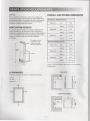
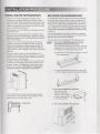
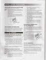
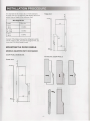
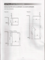
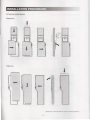
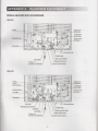
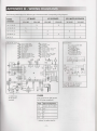
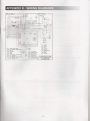
mn Dometic
INSTALLATION
MANUAL
NEA1402
NDA1402
autodefrost
FOR YOUR SAFETY
POUR VOTRE SECURITE
If you smell gas:
Si vous sentez une odeur de gaz:
1. Open windows.
2. Don't touch electrical switches.
3. Extinguish any open flame.
4. Immediately call your gas supplier.
1. Ouvrez les fenetres.
2. Ne touchez a aucun interrupteur.
3. Eteignez toute flam me nue.
4. Avertissez lmmediaternent votre
fournisseur de gaz.
FOR YOUR SAFETY
POUR VOTRE SECURITE
Do not store or use gasoline or other
flammable vapors and liquids in the
vicinity of this or any other appliance.
Ne pas entreposer ni utiliser de I'essence
ni d'autres vapeurs ou liquides inflammables a proxlmite de cet appareil ou de tout
autre appareil.
A AVERTISSEMENT
A WARNING
Improper installation, adjustment,
alteration, service or maintenance can
cause injury or property damage. Refer to
this manual. For assistance or additional
information consult a qualified installer,
service agency or the gas supplier.
A WARNING
Une installation, un reglage, une modification, une reparation ou un entretien non
conforme aux normes peut entrainer des
blessures ou des dommages materiels.
Lisez attentivement Ie mode d'emploi
fourni avec I'appareil. Pour obtenir de
I'aide ou des renseignements supplernentaires, consultez un installateur ou un
service d'entretien quallfie ou Ie fournisseur de gaz.
A AVERTISSEMENT
If the refrigerator stops cooling - or - if
ammonia emanates from it, immediately
turn the refrigerator off and contact a
Service Center.
I Si Ie retrigerateur cesse de refroidir - ou - si
de I'ammoniac s'en degage, arretez irnrnediatement Ie retrigerateur et contactez un
centre de reparation.
mD D0111etic
USA
Service Office
Dometic, LLC
2320 Industrial Pkwy.
Elkhart, IN 46516
Phone: 574-294-2511
825125902
©2006-2009. LLC
LaGrange, IN 46761
Corporate Office
2320 Industrial Parkway Elkhart, IN 46516
For Service Center Assistance
Call: 800-544-4881
CANADA
Dometic, LLC
46 Zatonski, Unit 3
Brantford, ON, N3T 5L8
CANADA
Phone: 519-720-9578
M00938
INTRODUCTION
3
CERTIFICATION AND CODE REQUIREMENTS
3
VENTILATION REQUIREMENTS
3
INSTALLATION PROCEDURE
5
APPENDIX A - REARVIEW EQUIPMENT.
10
APPENDIX B - WIRING DIAGRAMS
13
SYMBOLS
The following symbols are used throughout the manual:
AWARNING
Indicates a potentially hazardous situation, which, if not avoided, could result
in death or serious injury.
A CAUTION
Indicates a potentially hazardous situation, which, if not avoided, may result in
minor or moderate injury.
CAUTION
Used without the safety alert symbol indicates, a potentially hazardous situation which, if not avoided
may result in property damage.
Information
Step-by-step instructions
This product is manufactured under
license of U.S. Patent Number 6.019,447.
Patents pending
U.S. 101619,675
U.S. 101620,177
U.S. 101758,174
U.S. 101758,175
U.S. 101760,564
U.S. 101760.565
-2-
This manual describes how to install NEAl 402 (all-electric operation) and NDA1402 (2-way operation). These models can be
equipped with an ice maker, an ice dispenser or ice & water dispensers.
The information in this manual is intended for qualified technicians with knowledge and experience of absorption refrigerators
and LP gas systems. For operating instructions, please refer to the User manual for the appliance in question.
Read this manual before installing the refrigerator. Comply with installation specifications and dimensions. Follow the instructions
to ensure that the refrigerator is installed safely and that it runs efficiently. Be aware of possible safety hazards when seeing alert
symbols on the refrigerator as well as in this manual.
The appliance is certified under the latest edition of ANSI Z21.19·CSA 104 Refrigerators using gas fuel. The installation must
conform with local codes, or in absence of local codes, the following standards as applicable.
In the U.S. the installation must conform with:
• National Fuel Gas Code, ANSI Z223 .IINFPA 54 (latest edition).
• Recreational Vehicles Code, ANSI A 119.2 (latest edition)
• Manufactured Home Construction and Safety Standard, Title
24 CFR, Part 3280.
If an external electrical source is utilized, the refrigerator, when
installed, must be electrically grounded in accordance with local codes or, in the absence of local codes, the National Electrical Code, ANSIINFPA 70 - (latest edition).
In CANADA, the installation must conform with:
• Natural Gas and Propane Installation Code, CSA B 149.1
• CSA Z240 RV Series, Recreational Vehicles.
• Current CSA Z24004, Gas-equipped Recreational Vehicles
and Mobile Housing.
If an external electrical source is utilized, the refrigerator,
when installed, must be electrically grounded in accordance
with local codes or, in the absence of local codes, the Canadian
Electrical Code, CSA C22.1, Parts I and II - (latest edition).
@.
C
GENERAL INFORMATION
Provide necessary air circulation over the cooling unit. Openings for air supply or for venting of combustion products shall
have a minimum dimension of not less than 1/4 inch.
US
The lower vent of the recommended kits is provided with
proper size openings. The flow of combustion and ventilating
air must not be obstructed.
CAUTION
Certified installations require one roof vent and one lower side
vent. Proper installation requires one lower fresh air intake
and one upper exhaust vent. The ventilation kits shown in this
manual have been certified for use with NEA1402 and
NDA1402. The ventilation kits must be installed and used
without modification.
It is of especially importance tbat tbe airflow around
tbe burner housing, tbe boiler insulation and tbe
flow of combustion gases must not be obstructed.
Items placed in the vicinity of the refrigerator
compartment accordingly must be secured away
from the refrigerator tubing and flue.
Certified vent system kits
Kit no.
Components
Part no.
5A
Roof Base
Roof Cover
Lower Side Vent
Power Vent Asm.
3103633.xXX*
3103634.XXX*
3109349.XXX*
3108705.744**
The lower side vent is fitted with a panel, which provides an
adequate access opening for ready serviceability ofthe burner
and control manifold of the refrigerator. This should be centered on the back of the refrigerator.
*
Fill in '~\XX" with color code numbers. For color codes, contact
your supplier.
** Alternate instructions forwarded with the Ventilator Kit.
'~I_-------:::=-==--_-----.JI""'"
28-518·
-3-
vent cutout
NDA1402
OVERALL AND RECESS DIMENSIONS
When installing the refrigerator, make sure to separate the
combustion system from the living space of the mobile home
or recreational vehicle. An opening toward the outside at floor
level in the refrigerator compartment must be provided for
ventilation of heavier- than-air fuel gases.
..
OVERALL DIMENSIONS
Height (A)
mm
1632
64-17/64
inches
VENTILATION
HEIGHTS
Width (B)
It is essential that all maximum or minimum dimensions are
strictly maintained as the performance of the refrigerator is
dependent on adequate flow of air over the rear of the refrigerator. For an installation with roof vent and lower side vent, the
minimum ventilation height should be 69-1/8 inches
(1756 mm).
I
I
I
I
I
I
I
I
I
I
Ventilation
height
",,-
mOl
855
33-11116
inches
Depth (C)
mm
752
29-5/8
inches
The upper vent should
be centered over the
condenser coil at the
back of the refrigerator.
RECESS DIMENSIONS
Height (H)
mm
1605
63-3/16
inches
_-
Width (W)
.!:.-::::.'rI -- -::::::Vf*-----i--if-
...
H
I I
I I
I I
I
Depth (D)
mm
832
inches
32-3/4
mm
662*
inches
26-1116*
* Add 1" (25 mm) depth for units with one or two optional
ventilator fans.
SIDEVIEW
CLEARANCES
Minimum clearances (in inches) to combustible materials:
Top (G)
o
Side (K)
o
Bottom (L)
o
1
A
G
VIEW FROM ABOVE
c
B
- 4-
INSTALLING THE REFRIGERATOR
• Please use care when installing the refrigerator! This
refrigerator is equipped with the latest vacuum insulated
panel technology. These insulating panels are located on the
top, back, bottom, sides and doors ofthe refrigerator. If the
surface is punctured, loss of insulation will occur, resulting
in poor refrigerator performance.
• The refrigerator must be installed in a substantial
and must be level.
enclosure
SECURING THE REFRIGERATOR
It is important to follow the sequence in securing refrigerator
in enclosure since failure in doing so can cause leakage between the frame and cabinet. Any space between the counter,
storage area or ceiling and top of the refrigerator greater den
1-1/2 inches should be blocked. The heat produced at the rear
of the refrigerator will become trapped in this space, making
the top of the refrigerator hot and reduce the efficiency of the
refrigerator.
After the refrigerator is put in place (ensuring a combustion
seal at the front frame), the refrigerator is to be secured in the
enclosure with six screws (not included).
• Do not install the appliance directly on carpeting. Carpeting must be removed or protected by a metal or wood panel
beneath the appliance, which extends at least full width and
depth of the appliance.
• Clearances: In a proper installation there should be zero
inches (0") clearance surrounding the sides, top, bottom
and rear of the refrigerator to achieve proper air flow. All
potential dead air pockets should be blocked or baffled to
ensure that heat won't be trapped in these spaces and reduce
efficiency.
The six screws have to be installed in the following
~
order:
1. Two screws installed
througb the front base.
(Installation
of the lower front strip.)
The refrigerator is provided with a lower front strip
(shipped as a loose part). Attach the front strip after
the refrigerator is set into the cutout opening.
a) Install the lower front strip by sliding it under the
bottom hinge plates.
• All areas within the recess in which the refrigerator
is
installed must be sealed. Make sure that there is a complete
seal between the front frame of the refrigerator and the top,
sides and bottom ofthe enclosure.
A length of sealing strip is applied to the rear surface of the
front frame for this purpose. The sealing should provide a
complete isolation of the appliance's combustion system
from the vehicle interior. Be careful not to damage tbe
sealing strip when the refrigerator
is put in place!
b) Secure the refrigerator and the lower front strip
with two screws - one screw through each hinge.
2. Two screws installed in be top frame.
Open the doors and
fasten the refrigerator
with two screws through
the holes underneath the
top decoration panel.
• A wood strip must be in place across the upper opening
of the enclosure. The top frame ofthe refrigerator will be
anchored to the wood strip with screws.
Wood strip
3. Two screws installed
-5-
in tbe rear base.
r--------------------------~------~--------------------------~
INSTALLING THE DRAIN WATER HOSE
To install the drain water hose, follow these steps:
~
4. Wait for approx. 6-7 minutes. The message
"ch LP" is displayed (flashing).
5. Remove the protection cover.
1. Drill a hole through flooring. It is essential that it is
drilled in the cut out opening of the base plate at the
rear of the refrigerator.
6. Open the manual gas shut off valve. (Do not change
any button positions on the control panel.)
2. Make sure that the hose does not kink when run
through the floor.
3. Seal around the hose that goes through the drilled
hole. If a longer hose than supplied is required, the
installer needs to supply one in order for the water to
drain outside of the vehicle.
7. Apply a non corrosive commercial bubble solution
to the burner jet orifice. No bubbles should appear at
the opening of the burner jet orifice. The presence of
bubbles indicates a defective gas safety shut off, and
service is required.
8. If no bubbles were present at the burner jet orifice,
rinse it with fresh water. Be careful not to damage
the burner jet orifice.
9. Put back the cover.
10. Switch the refrigerator OFF and back ON again.
Normal operation of the burner should return.
11. Allow the burner to operate for a minimum of 5
minutes
Hole for drain
waterhose
ELECTRICAL CONNECTION
120VAC CONNECTION
GAS CONNECTION
The refrigerator is equipped with a three-prong (grounding)
plug for your protection against shock hazards and should be
plugged directly into a properly grounded three prong receptacle. DO OT cut or remove the grounding prong from this
plug!
(NDA1402)
Hook up to the gas supply line is accomplished at the manual
gas valve, which is furnished with a 3/8" SAE (UNF 5/8" -18)
male flare connection. All completed connections should be
checked for leaks with a non corrosive commercial bubble
solution.
A
The free length of the cord is 2 feet and it is recommended that
the receptacle is located to the right side of the refrigerator
(viewed from the rear).
WARNING
EXPLOSION HAZARD. Never use an open flame
to check for gas leaks. Failure to heed this warning could cause an explosion resulting in death or
severe personal injury.
The receptacle should be 3" (from
the bottom of the plastic receptacle)
above the refrigerator mounting floor.
This allows easy access through the
vent door. The cord should be routed
to avoid direct contact with components that could damage the cord
insulation.
The gas supply system must incorporate a pressure regulator
to maintain a supply pressure of not more than It inches water
column. When testing the gas supply system at test pressures:
120VoitAC
receptacle
3"
• > 112 psi - the refrigerator and its individual shutoff valve
must be disconnected from the gas supply piping system.
12V DC CONNECTION
• ~ 112 psi - the appliance must be isolated from the gas
supply piping system by closing its individual manual shutoff valve.
The refrigerator requires a continuous 12 V DC supply to maintain the automatic energy selector system and the auto defrost
control system to function.
For detailed instructions on the installation and connection to
the gas supply, contact your dealer or distributor.
The connection is made to the positive (+) and negative (-)
terminals ofthe terminal block on the back of the refrigerator.
TESTING LP GAS SAFETY SHUT OFF
The gas safety shut off must be tested after the refrigerator is
connected to LP gas supply. To test the gas safety shut off, follow these steps:
Correct polarity must be observed when connecting to the DC
supply. Do not use the chassis or vehicle frame as one of the
conductors. Connect two wires at the refrigerator and route to
the DC supply.
~
Maximum fuse size for the DC supply is lOA.
1. Turn on the refrigerator and switch to GAS mode.
2. Check that the GAS indicator dot is illuminated and
the gas flame is lit.
3. Close the manual gas shut off valve at the back of
the refrigerator.
-6-
It is important that the wires to the 12 V DC terminal is
of proper wire size. The following table displays the recommended size and length of the conductor wires.
Fridge door
~~
~
51
~
Wire length & size
Length
Min. size
< 33 ft
<10m
12AWG
33 - 66 ft
]0 - 20 m
IOAWG
> 66 ft
>20m
8AWG
1a.111
"'"
.-
~
~
•
~
~
Example: If the distance between the refrigerator and the
] 2V DC supply is 20 ft., the total wire length is 40 ft. and
a wire size of lOAWG should be used.
~
~
i
•
MOUNTING THE DOOR PANELS
".'"
0»,
.,'" ...
"""'"
~
MODELS EQUIPPED WITH ICE MAKER
t
DOOR PANEL DIMENSIONS
FITTING THE DOOR PANELS
Freezer door
=
-,
1
....,
11.181
III
1AAJ(1.00
,o.wc2S)
-7-
i
MODELS
EQUIPPED WITH ICE DISPENSER
liCE
& WATER DISPENSERS
DOOR PANEL DIMENSIONS
Fridge door
Freezer door
;;;-
~"
+1
0
~
+
.197 (2x) (5)(2x)
.197(2x)
(5)(2x)
+
16.B11
(427)
MAX 1.00
(MAX 25)
~~
D>
9370 (238)
913 (23 2)
I
.197(2x) (5)(2x)
I
"'
+ I
"''"
~
~
•... '"
~~
+
-
i-
12.756
(324)
..•
I
l'l
g
MAX 1.00
(MAX 25)
'"
t::-
~
;1j
'"~
O>
1ii
c»
'"
15.237
(3B7)
MAX 1.00
(MAX 25)
'j
t::-
,
~
-8-
FITTINGTHE DOOR PANELS
Freezer door
l
l
000 6
000
FWU
~
/)
---wo
000 0
WO
~
l
~
••••
III
Fridge door
l
=
l
III
Model shown: NEA 1402fNDA 1402 with ice and water dispensers.
-9-
MODELS EQUIPPED WITH ICE MAKER
NEA1402
Heaters
Protection cover
Power module
and fuses
Drain water hose
Thermostat
Water solenoid valve
Flexible cord Ice maker
12 Volt DC Terminal block
NDA1402
Heat.ers
Flexible cord
Refrigerator
12V DC
Burner control
Protection cover
Power module
and fuses
Flue baffle
Thermofuse
Flexible cord Ice maker
- 10-
MODELS EQUIPPED WITH ICE DISPENSER
NEA1402
Heaters
Flexible cord
Refrigerator
Ice dispenser
power switch
Protection cove r
Power module
and fuses
Thermofuse
Drain water hose
Flexible cord
Ice maker, Ice dispenser
NDA1402
--
---;==-::- =--:JL=:!~lrF=--===-::r- :::c::--~--~-;a-~r-1\.~j~~~======~~E~II~9f;;;;;;~;;~~~
l(r~~l~~======~~E~III~1~;;;;~;;~~~
I '~'~I~~======~~E=~llr~I~;;;;~~~~::~
\.r:lc=====zz:;;clFlIIf--=JCtr=;=:=~=:~
--nT--re.:
II I
II I
,-,H~e""at~e:.!rs'--
-H-+--.JLlIIII
II
I
I
Flexible cord
~~~~~~;:~~~~=r:sc:~
P
12VDC
Burner control
II I
I
=:':":"=':"'::;=:'="--U~4..1
I
Protection cover
Flue baffle
IL
I
I
----- ~
:
E
~ ~
~
!,u ::::::r- rk- Ii
0
~\J
0
~f;>
----#-l-L~--ll I: I---"~
T-'-'.h=er"-'-m=of=us=e'------ ~
~
-II ~
Burner jet /
Manual gas shut off valve
~~:~II~
----
'T- I
r ~of".L-1'?P
((((~--'Jn--.=~o 1-=----1
@:~ ,,~.~ 'r=r:~\v00 ~
1/
__R~e~f~rig=e=r=at=o=r~
I
Ice dispenser
power switch
IIII@
i!:lI
~~~~~~~
---
..
~
~~
~
------.ur
A\ ~ •• ,
~
[]
I
[
Power module
~===:J=='--'-~tll1l-,-a_nd_fu_se_s_
IJ
II
...~
~~b )()]~
..~~~~=-'=:i:~ldJ
:.
Inlet fitting
= i=
\
~
. \
Drain water hose
Heating cable
~
Water hose (Ice maker)
Thermostat
Water solenoid valve
Flexible cord
Ice maker, Ice dispenser
12 Volt DC Terminal block
- 11 -
MODELS EQUIPPED WITH ICE AND WATER DISPENSER
NEA1402
I
I
I
I
Healers
--
I
~.<..
I
I
I
.l
l
l
I I r---II-
I
Pro:ection cover
~
L 1"1I
I
I I
I I
II II
I
I
I
I
I
II
I I
I
E
---
--
--
.J
~-~;:J
------':":'JA
~ if;>
'--
S C9.,e~
II-"-.)!
/.
---®
~f.£-~~
0
--
P
®
r-
J :~
--
--
»>
"
L-
~
1'lennofuse
--
--TT--'C::'- ,----
-
---
---
- r
~
Flexible cord refrigeralor
~
I
Dispenser power switch
I.
8~
0'--
~
Power module and fuses
or--
:;~'.~~Jn*Gb 91~
*i L = ==-' - rr
~c
~
90· connection, water dispenser
j,
,@
~.,
~
••
~
••
-;be'Tllos:a\
DCTe~;",1 block
12 Yolt
~
J
/
Drain water hose
Hose, water dispenser
Hose, icemaker
Flexible cord
Ice maker, Ice dispense
Heating cable
Water solenoid valve
NDA1402
- -- lTT-- 'C ,---II I
r--r-
II I
III
II I
Heaters
--
l.
.l.
,l.
--
.
J-Lll.
12VDC
Burner control
itiiJ ~~71
lil~~I
II
I
Protection cover
Rue baffle
--
----.LA
L--
11,/1
~
I I
--
~
I
----i-h-]I
@
I--
I:
Burner jet /
9" shut off valve
• ~
.~
I~
•
0
0
-
..--c::L
r
Flexible cord refrigerator
I J
Dispenser power switch
••
=
III
•
ei
"''''c
'
~~
r.-
~
•••
F===V
=
~
••
~
Hose, water dispenser
Thermostat
Hose, icemaker
Flexible cord
Ice maker, Ice dispenser
..-...
---
Power module and fuses
0
?'fJ
/
I/ i
Inlet fitting
--
11--
--
r--
11_
'<.!!JjI"".~
e
~~
C]§®~
J!;Lll-.!:l
r
,@....
","",I
0
(
--
p
.,
.~
~II/,I
Ip
Thermofuse
__
--
--
Heating cable
Water solenoid valve
12 Volt DC Terminal block
- 12 -
11~
-
IT
90° connection, water dispenser
~
Drain wa:er hose
The following table displays the different types of models and their corresponding wiring diagrams.
ICE MAKER
WIRING
DIAGRAM
NEA1402
NDA1402
(2)
X
385 ]325 (2)
X
3850897
NEA1402
ICE & WATER DISPENSERS
NDA1402
NEA1402
X
X
X
X
X
(3)
X
X
385 11 12
385
13 24
NDA1402
X
X
385 13 24 (2)
3850699
ICE DISPENSER
2
0=- CIRCUIT BOARD
®- CIRCUIT BOARD
cv=12V DC BURNER
®- SViITCH FREEZER
~
LAMP FREEZER
®- SViITCH FRIDGE
~
LAMP
®- FAN
~
®co=®~
®=- ELECTRODE
®- SOLENOID VALVE
®-::THERMOSTAT
®- FAN FREEZER
cv=HEATING
ELEMENT
0- HEATING ELEMENT
cv=TERMINAL
BLOCK
0- THERMOFUSE
POWER
DISPLAY
CONTROL
FRIDGE
FRIDGE
THERMISTOR
THERMISTOR
FRIDGE
FRIDGE
THERMISTOR
THERMISTOR
FREEZER
FREEZER
CHASSIS
AIR
FLANGE
AIR
FLANGE
cv=@cv=@-
HEATING
HEATING
385
GROUND
2
®-=DRAIN
FRIDGE
TRAY
CIRCUIT BOARD POWER
® ICEMAKER
®--:- WATER VALVE
QD HEATING
CABLE
THERMOSTAT
Q) CHASSIS GROUND
~
PROTECTIVE
EARTH
QD SPLICING SLEEVE
~
CABLE
FRONT
FRAME
ELEMENT
FREEZER
PROTECTIVE
HEATER
120V
06 99
X
EARTH
AC
~
®
®
e
t~~~~~I~~
..
BLACK
7
liED
J
8 1
RED
RED
&lACK
8
lELLOW
.•.«rn
2
5
®
10
,,"
.ED
~:~~~~
o
SLACK
liED
CDYEllO"
~
liED
8L"CK
1
fAN
120
V AC
IN OPERATION
THE ICE·MAKER
WILL ADD 1.4 AMPS TO THE
TOTAL REFRIGERATOR
DRAW
+ 12V DC
3A inline fuse
for the power
vent fans
(9
N L
FUSES
Fuses (from left to right) protect
the following components.
Fuse
Type of component
3A
A, B, C, E, G, H, P, R
7.5A
S, T
3A
W*
7.5A
X
5A
Z
* Optional
ice maker heat-kit
- l3 -
-
::=:U:
::D- ::==
""'--
0 :-C
~
_' =
,,--;
:~-
BOARD
_'
:::r
,
=,
FREEZER
FRIDGE
fRIDGE
--"qUISTOR
--",UISTOR
& --=qUISTOR
~-
--"
UISTOR
CHASS I S GROUND
®- FAN FREEZER
cv-=HEATING
ELEMENT
®- HEATING ELEMENT
~
TERMINAL
BLOCK
®- THERMO FUSE
DISPLAY
fREEZER
H FRIOGE
:~
®-::--
POWER
T BOARD
cv=@cv=0-
FRIDGE
FRIDGE
AIR
FLANGE
FREEZER
AIR
FREEZER
FLANGE
CD=-
o
CD
HEATING
HEATING
TRAY
FRIDGE
CABLE
FRONT FRAME
ELE~IENT
FREEZER
THERMOSTAT
PROTECTIVE
HEATER
DRAIN
EARTH
120V
AC
FUSES
Fuses (from left to right) protect
the following components.
<
;:;
<
. <
;:;
Fuse
Type of component
3A
A, B, D, F, G, N
7.5A
O,P
3A
T*
7.5A
U
5A
Z
0_
,
"
0
'0 "
~~
F~RT
..
0
~
e
®
.~ ~a
* Optional
~ the power vent fans
~
0
..
""
lUCk
,e
~y:~~~!
:e "" ,,
n,t,Ck
;;;
JlJ,CJ(
oauSE
:!!••:; ~
00
<
<
",
~~
nIT
"
,
000
-a
000
,
~
'O'fiR
>onR
SWITCH
®
"'"
::E
?Z-
~~~
~~~:-:~
::,,--
<31 f'EATING
:;: - ::E ::,,;:IS3I
COJfTROl
GHT
120 V AC
;;;
.<
®- FLEX CAB LE
BLOCK
®- WATER VALVE
HEATING
CABLE
CD- THERUOSTAT
CD-::- TERMINAL
CABLE
~
BOARE
cv=CD-
CHASSIS
GROUND
PROTECTIVE
EARTH
CD-:-
BLACK
CD- BROWN
CD::- RED
0- YELLOW
~GREEN
®- GREEN/YELLOW
c:v-=--
B L UE
GREY
@-=-WHITE
CD-
IN OPERATION
THE
AND ICE DISPENSER
4,5 A TO THE
REFRIGERATOR
- 14-
ICE MAKER
WILL ADD
TOTAL
DRAWl
ice maker heat-kit
r
385
11
12
F=-,:=====---------j?'-3
-t--t============1
Pl·"
P1 1
r
,
· ...
··
t
,
,
P'-2
'
m
JUU
P2
PO
.un
HUE
'~n
.u.tI:
TELL~'
, •un
" '"
,
···
,
0::- CIRCUIT
CD~
®cv=CD-
®-::®c:D-=:--0-
~
<
::~''I:;~
00
:;
-<
IIl~~~
:: 5l:~~.
0
IlA"
O~"'UE
3
4
,
,s
~,~~~!:
nAtI(
,
"""l.
/lUT
m
:;
~.~
~~
::;
=~=
000
",
000
~
AUGER
CRUSCH
ICE DISPENSER
ICE DISPENSER
ICE DISPENSER
ICE DISPENSER
V AC
CD:- BLACK
CD- BROWN
®::--- RED
0- YELLO\!
®-:=-
BOARO POWER
ICE DISPENSER
FUSE SA
ICE ~AKER
120
POWER SWITCH
CD-
®
~
®- FLEX
CD::-
®-
®-=--
HEATING
CABLE
~
CONTROL
LIGHT
BOARE
cu=-®-
®-
CABLE
TERUINAL
BLOCK
WATER VALVE
HEATING CABLE
THERMOSTAT
CHASS IS GROUND
PROTECTIVE
EARTH
GREEN
GREEN/YELLOW
BLUE
CD-GREY
WHITE
IN OPERA nON
THE ICE MAKER
AND ICE DISPENSER
WILL ADD
4,5 A TO THE TOTAL
REFRIGERATOR
ORAW!
- 15 -