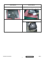
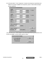
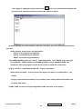
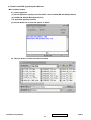
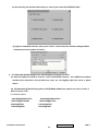
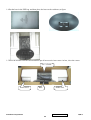
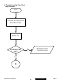
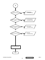
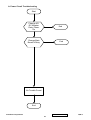
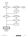
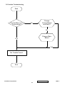
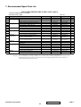
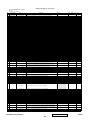
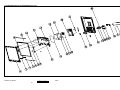
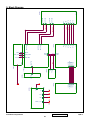
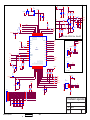
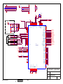
1
Service Manual
ViewSonic Q9b-2
Model No. VS11201
19” Color TFT LCD Display
(Q9b-2_SM Rev. 1b Aug. 2006)
ViewSonic 381 Brea Canyon Road, Walnut, California 91789 USA – (800) 888-8583
Copyright
Copyright © 2006 by ViewSonic Corporation. All rights reserved. No part of this publication
may be reproduced, transmitted, transcribed, stored in a retrieval system, or translated into any
language or computer language, in any form or by any means, electronic, mechanical, magnetic,
optical, chemical, manual or otherwise, without the prior written permission of ViewSonic
Corporation.
Disclaimer
ViewSonic makes no representations or warranties, either expressed or implied, with respect to
the contents hereof and specifically disclaims any warranty of merchantability or fitness for any
particular purpose. Further, ViewSonic reserves the right to revise this publication and to make
changes from time to time in the contents hereof without obligation of ViewSonic to notify any
person of such revision or changes.
Trademarks
Optiquest is a registered trademark of ViewSonic Corporation.
ViewSonic is a registered trademark of ViewSonic Corporation.
All other trademarks used within this document are the property of their respective owners.
Revision History
Revision
SM Editing Date
1a
05/02/2006
1b
08/22/2006
ECR Number
VS-E060267
VS-E060268
Description of Changes
Editor
Initial Release
Jamie Chang
Add 2nd panel source(HSD190ME-A10/A16)
(updated RSPL, BOM, Spec.)
Jamie Chang
ViewSonic Corporation
Confidential - Do Not Copy
i
Q9b-2
TABLE OF CONTENTS
1.
Precautions and Safety Notices
1
2.
Specification
5
3.
Front Panel Function Control Description
14
4.
Circuit Description
20
5.
Adjustment Procedure
25
6.
Troubleshooting Flow Chart
45
7.
Recommended Spare Parts List
53
8.
Exploded Diagram and Exploded Parts List
58
9.
Block Diagram
61
10. Schematic Diagrams
62
11. PCB Layout Diagrams
69
ViewSonic Corporation
Confidential - Do Not Copy
ii
Q9b-2
1. Precautions and Safety Notices
1. Appropriate Operation
(1)
(2)
(3)
(4)
(5)
(6)
(7)
(8)
(9)
(10)
Turn off the product before cleaning.
Use only a dry soft cloth when cleaning the LCD panel surface.
Use a soft cloth soaked with mild detergent to clean the display housing.
Use only a high quality, safety approved AC/DC power cord.
Disconnect the power plug from the AC outlet if the product will not be used for a long period of time.
If smoke, abnormal noise, or strange odor is present, immediately switch the LCD display off.
Do not touch the LCD panel surface with sharp or hard objects.
Do not place heavy objects on the LCD display, video cable, or power cord.
Do not use abrasive cleaners, waxes or solvents for your cleaning.
Do not operate the product under the following conditions:
- Extremely hot, cold or humid environment.
- Areas containing excessive dust and dirt.
- Near any appliance generating a strong magnetic field.
- In direct sunlight.
2. Caution
No modification of any circuit should be attempted. Service work should only be performed after you are thoroughly familiar
with all of the following safety checks and servicing guidelines.
3. Safety Check
Care should be taken while servicing this LCD display. Because of the high voltage used in the inverter circuit, the voltage is
exposed in such areas as the associated transformer circuits.
4. LCD Module Handling Precautions
4.1 Handling Precautions
(1) Since front polarizer is easily damaged, pay attention not to scratch it.
(2) Be sure to turn off power supply when connecting or disconnecting input connector.
(3) Wipe off water drops immediately. Long contact with water may cause discoloration or spots.
(4) When the panel surface is soiled, wipe it with absorbent cotton or other soft cloth.
(5) Since the panel is made of glass, it may break or crack if dropped or bumped on hard surface.
(6) Since CMOS LSI is used in this module, take care of static electricity and ensure human earth when handling.
(7) Do not open or modify the Module Assembly.
(8) Do not press the reflector sheet at the back of the module in any direction.
(9) In the event that a Module must be put back into the packing container slot after it was taken out of the
container, do not press the center of the CCFL Reflector edge. Instead, press at the far ends of the
CFL Reflector edge softly. Otherwise the TFT Module may be damaged.
(10) At the insertion or removal of the Signal Interface Connector, be sure not to rotate or tilt the Interface
Connector of the TFT Module.
ViewSonic Corporation
Confidential - Do Not Copy
1
Q9b-2
(11) After installation of the TFT Module into an enclosure (LCD monitor housing, for example), do not twist or
bend the TFT Module even momentarily. When designing the enclosure, it should be taken into consideration
that no bending/twisting forces may be applied to the TFT Module from outside. Otherwise the TFT Module
may be damaged.
(12) The cold cathode fluorescent lamp in the LCD contains a small amount of mercury. Please follow local
ordinances or regulations for disposal.
(13) The LCD module contains a small amount of materials having no flammability grade. The LCD module
should be supplied with power that complies with the requirements of Limited Power Source
(IEC60950 or UL1950), or an exemption should be applied for.
(14) The LCD module is designed so that the CCFL in it is supplied by a Limited Current Circuit (IEC60950
or UL1950). Do not connect the CCFL to a Hazardous Voltage Circuit.
ViewSonic Corporation
Confidential - Do Not Copy
2
Q9b-2
Handing and Placing methods
Correct methods
Only touch the metal frame of the LCD panel or the
Incorrect methods
Surface of the LCD panel is pressed by fingers and that
front cover of the monitor, DO not touch the surfaceof may cause”mura”
the POL
Take out the monitor with cushions
Taking out the monitor by grasping the LCD panel, that
May cause”mura”
ViewSonic Corporation
Confidential - Do Not Copy
3
Q9b-2
Correct methods
Place the monitor on a clean and soft foam pad
Incorrect methods
Placing the monitor on a foreign objects, that could
scratch The surface of the "Panel" or cause "mura"
The panel is placed facedown the lap,that may cause
"mura"
ViewSonic Corporation
Confidential - Do Not Copy
4
Q9b-2
2. Specification
2-1 GENERAL specification
Test Resolution & Frequency
1280x1024 @ 75Hz
Test Image Size
Full Size
Contrast and Brightness Controls
Factory Default:
Contrast = 90%, Brightness = 100%
2-2
VIDEO INTERFACE
Input Connector (refer the appendix A)
DB-15 (Analog)
Default Input Connector
Defaults to the first detected input
Video Cable Strain Relief
Equal to twice the weight of the monitor for five
minutes
Video Cable Connector DB-15 Pin out
Compliant 2B
Video RGB (Analog)
Video Signals
Separate Sync
TMDS (Digital)
Video Impedance
75 Ohms (Analog), 100 Ohms (Digital)
Maximum PC Video Signal
950 mV with no damage to monitor
Maximum Mac Video Signal
1250 mV with no damage to monitor
Sync Signals
TTL
DDC2B
Compliant with Revision 1.0
Sync Compatibility
Separate Sync
Video Compatibility
Shall be compatible with all PC type computers,
Macintosh computers, and after market video
cards
Resolution Compatibility
640x350, 720x400, 640x480, 800x600, 832x624,
1024x768, 1152x864,
1152x870, 1280x960, 1280x1024
Exclusions
Not compatible with interlaced video
2-3
N/A
USB INTERFACE
ViewSonic Corporation
Confidential - Do Not Copy
5
Q9b-2
2-4
POWER SUPPLY
Internal Power Supply
FSP FSP035-1PI01ZT
Input Voltage Range
90 to 264 VAC
Input Frequency Range
47.5 to 63 Hertz
Short Circuit Protection
Output can be shorted without damage
Over Current Protection
5.0 A typical at 12.0 VDC
Leakage Current
3.5mA (Max) at 254VAC / 60Hz
Efficiency
80 % typical at 115VAC Full Load
Fuse
Internal and not user replaceable
Power Dissipation
36W(typ) 40W(max)
Max Input AC Current
1.5 Arms @ 90VAC, 0.75 Arms @180VAC
Inrush Current (Cold Start)
50 A (max) @ 115VAC
90 A (max) @ 230VAC
Power Supply Cold Start
Shall start and function properly when under full
load, with all combinations of input voltage, input
frequency, and operating temperature.
Power Supply Transient Immunity
Shall be able to withstand an ANSI/IEEE
C62.41-1980 6000V 200 ampere ring wave
transient test with no damage.
Power Supply Line Surge Immunity
Shall be able to withstand 1.5 times nominal line
voltage for one cycle with no damage.
Power Supply Missing Cycle Immunity
Shall be able to function properly, without reset or
visible screen artifacts, when ½ cycle of AC power
is randomly missing at nominal input.
Power Supply Acoustics
The power supply shall not produce audible noise
that would be detectable by the user. Audible
shall defined to be in compliance with ISO 7779
(DIN EN27779:1991) Noise measurements of
machines acoustics. Power Switch noise shall not
be considered.
Power Saving Operation(Method)
VESA DPMS Signaling
On Mode < 36W(Typ) / 40W (max)
Power Consumption
Active Off < 1 W @ 120 Vac /
< 1.5W @ 220Vac
Recovery Time
On Mode = N/A, Active Off < 3 sec
ViewSonic Corporation
Confidential - Do Not Copy
6
Q9b-2
2-5
ELECTRICAL REQUIREMENT
Horizontal / Vertical Frequency
Horizontal Frequency
30 – 80 kHz
Vertical Refresh Rate
55 – 75 Hz.
Maximum Pixel Clock
135 MHz
Sync Polarity
Independent of sync polarity.
Timing Table
Timing
SOG
Composite
Separated
Item
Digital - TMDS
Analog
Remark
The vertical image size might not full
1
640 x 350
@ 70 Hz, 31.5 KHz
screen
(Vertical position = center).
2
640 x 480
@ 60 Hz, 31.5 KHz
3
640 x 480
@ 67 Hz,
4
640 x 480
@ 72 Hz, 37.9 KHz
5
640 x 480
@ 75 Hz, 37.5 KHz
6
720 x 400
@ 70 Hz, 31.5 KHz
7
800 x 600
@ 56 Hz, 35.1 KHz
8
800 x 600
@ 60 Hz, 37.9 KHz
9
800 x 600
@ 72 Hz, 48.1 KHz
10
800 x 600
@ 75 Hz, 46.9 KHz
11
832 x 624
@ 75 Hz, 49.7 KHz
12
1024 x 768
@ 60 Hz, 48.4 KHz
13
1024 x 768
@ 70 Hz, 56.5 KHz
14
1024 x 768
@ 75 Hz, 60.2 KHz
15
1152 x 864
@ 75 Hz, 67.5 KHz
16
1152 x 870
@ 75 Hz, 68.7 KHz
17
1280 x 960
@ 60 Hz, 59.7 KHz
18
1280 x 1024
@ 60 Hz,
64
KHz
19
1280 x 1024
@ 75 Hz,
80
KHz
35
KHz
Primary Presets
1280x1024 @ 75Hz
User Presets
Number of User Presets (recognized timings) Available: 10 presets total in FIFO configuration
Changing Modes
● Maximum Mode Change Blank Time for image stability : 3 seconds (Max), excluding “Auto Adjust” time
● The monitor needs to do “Auto Adjust” the first time a new mode is detected
(see section “0-Touch™ Function Actions”)
● While running Change Mode, Auto Adjust or Memory Recall, the image shall blank
ViewSonic Corporation
Confidential - Do Not Copy
7
Q9b-2
2-6
FRONT PANEL CONTROLS AND INDICATORS
Front Panel Hardware Controls
Power Switch (Front Head)
Power Control, soft Power Switch.
Power LED (Front Head)
Green – ON
Orange – Active Off
Dark = Soft Power Switch OFF
Front Panel Controls
(Head; From left to right)
Reaction Time
Button
Icon
Function
Button1
Select(backward)
Button2
Select(forward)
Button3
Power
Button4
-
Adjust Down
Button5
+
Adjust Up
OSD must fully appear within 0.5s after pushing Button 1
Short Cuts Function from the button(s)
Button 1
Auto Image Adjust.
Button 2
Main Menu
Button 4
Mute on/off
Button 5
Volume OSD
Button 4 + Button 5
+ Button 3
Factory Mode
(The Burning mode is build in Factory mode)
Remark : All the short cuts function are only available while OSD off
ViewSonic Corporation
Confidential - Do Not Copy
8
Q9b-2
Function descriptions
Main Menu Controls
The Main Menu OSD include most of control functions.
Please refer to APPENDIX B (Main Menu OSD Table) for the detail.
Factory Default OSD Actions
Memory Recall action on the analog and digital mode as below
1. Set the factory defaults as shown in Section 2-8
2. Clean all the mode setting buffer
3. Execute Auto Image Adjust
0-Touch™ Function Actions
1. Execute Auto Image Adjust when new mode detected, and save the settings to buffer for
further use
2. It should be reset by Memory Recall function
(Should not reset by power off, power unplug and others)
OSD Auto Save
The OSD shall save new settings when it is turned off by the user or when it times out.
There shall not be a separate save
Factory Defaults
Item
Defaults
Contrast
90
Brightness
100
Color Setting
NATIVE
ViewSonic Corporation
Confidential - Do Not Copy
9
Q9b-2
2-7
AUDIO INTERFACE (SPEAKER SPECIFICATION)
Speaker specification
Line input connection
3.5 mm stereo jack
Line input signal
0.7 Vrms
Line input impedance
18 kOhm
Maximum power output (Electric)
1 W@ < 15 % distortion
Signal to Noise Ratio
50 dB
Frequency response
200 Hz – 10 Khz
Distortion
< 5 % THD (@1kHz)
Vibration
There should be no audible vibration with
volume at 100% and treble / bass at
default.
Screen image
There should be no affect on the screen
image stability under any conditions.
Connector PC99 requirement Audio in
Lime Green pantone # 577C
Cable type / length
3.5mm stereo cable / 1.8m length
Audio DPMS
Speakers should be off when the rest of
the monitor is in power saving.
Sympathetic
Under following conditions, there should
be no sympathetic heard
1. input <=0.7Vrms
2. Volume OSD <=80
Distance =30cm ±5cm
ViewSonic Corporation
Confidential - Do Not Copy
10
Q9b-2
2-8
st
Panel Characteristics :
nd
1 and 2 Source Panel
Model number
Type
Active Size
Pixel Arrangement
Pixel Pitch
Glass Treatment
# of Backlights
Backlight Life
Luminance (Center) –
CCT = User Color (R/G/B=100%),
Contrast/ Brightness = Max
Brightness Uniformity
Contrast Ratio
Color Depth
Viewing Angle H, V, D (CR >10)
Viewing Angle H, V, D (CR >5)
Response Time
10%-90% @ Ta=25°C
Mercury
Panel Defects
1st Source Panel: Hannstar HSD190ME13-A16
nd
2 Source Panel: Hannstar HSD190ME13-A10
Active Matrix TFT, TN technology
19”
RGB Vertical Stripe
0.294 mm
Anti-Glare
4 CCFL
40000 Hrs (Min)
50000 Hrs (Typ)
300 cd/m2 (Typ after 30 minute warm up)
240 cd/m2 (Min after 30 minute warm up)
75 % (Typ) / 70 % (Min)
700 :1 (Typ)
450 : 1 (Min)
16.2 million colors (6+2 bit panel)
Typical:
H = 150 degrees
V = 135 degrees
Minimum:
H = 130 degrees
V = 115 degrees
Typical:
H = 160 degrees
V = 155 degrees
On/Off
Typical = 8 ms
Maximun = 12 ms
3.0 mg per lamp
Please see Panel Quality Specifications.
*Over 50% units per shipment shall meet the Typical value above.
ViewSonic Corporation
Confidential - Do Not Copy
11
Q9b-2
2-9
IMAGE PERFORMANCE
Display Size
Horizontal Display Size, Primary Preset
Full Screen
Vertical Display Size, Primary Preset
Full Screen
Luminance
Lv (Max) –Condition:
Brightness / Contrast = 100%
Color Temperature = User (R/G/B=100)
Lv (Max) = The Luminance requirement of
section 2-6 “TFT LCD PANEL”
Lv (NATIVE) –Condition:
Brightness = Default / Contrast = Default
Lv (NATIVE) / Lv (Max) x 100% > 85%
Color Temperature = NATIVE
Lv (COOL) –Condition:
Brightness = Default / Contrast = Default
Lv (COOL) / Lv (Max) x 100% > 70%
Color Temperature = COOL
Lv (WARM) –Condition:
Brightness = Default / Contrast = Default
Color Temperature = WARM
Lv (WARM) / Lv (Max) x 100% > 70%
Contrast Ratio
CR(Max) –Condition:
Contrast / Brightness = 100%
Color Temperature = User (R/G/B=100)
Same as the Contrast Ratio in section 2-6
“TFT LCD PANEL”
Saturation
Contrast = Default
Brightness = Default
Test pattern = 128-gray
No visible saturation
Preset Color Temperatures
Color Temperature = WARM
(CCT around 5500K)
x = 0.332 ± 0.03
y = 0.348 ± 0.03
Color Temperature = NATIVE
(CCT around 6500K)
x = 0.313 ± 0.03
y = 0.329 ± 0.03
Color Temperature = COOL
x = 0.283 ± 0.03
(CCT around 9300K)
y = 0.298 ± 0.03
Video Cards Compatibility
Peaking Performance : Peaking is not adjustable
Raster Artifacts
● Video Artifacts : No visible streaking, sag, or smearing artifacts when driven by the
specified video cards in the primary mode and after user adjustment to best condition
● Power Supply, and Grounding Artifacts : No visible artifacts in any specified video mode
within the horizontal or vertical frequency range of the monitor
● Temperature Drift : Image shall not drift or lose fine-tune adjustment
ViewSonic Corporation
Confidential - Do Not Copy
12
Q9b-2
2-10 MECHANICAL
Desktop
Dimension
418 mm (W) x 408 mm (H) x 184 mm (D)
16.5" (W) x 16.1" (H) x 7.2" (D)
Monitor Weight
4.9 Kg (10.8 lbs)
Head Only / Wall Mount
Dimension
418 mm (W) x 363 mm (H) x 57 mm (D)
16.5" (W) x 14.3" (H) x 2.2" (D)
Monitor Weight
4.6 Kg (10.1 lbs)
Ergonomics
Tilt Up
+15º ±2 º
Tilt Down
-5 º ±2 º
Cabinet Material
Display Head Plastic Material
ABS-94HB
Neck/Base Plastic Material
ABS-94HB
Internal Plastic Cabinet Components
All internal plastic cabinet components shall be
in compliance with the requirements of MPR II
Front Bezel Color
The reference for the Front Bezel is the Black
color chip provided by ViewSonic
The color difference between any two cabinet
components shall be less than 0.80 “Delta E”,
in the 1976 CIE L*a*b Colorspace.
Neck, Base, Speaker Cover, Rear Cover
and Rear Logo Color
The reference for the Neck, Base, Speaker
Cover, Rear Cover and Rear Logo is the Black
color chip provided by ViewSonic
The color difference between any two cabinet
components shall be less than 0.80 “Delta E”,
in the 1976 CIE L*a*b Colorspace.
Cabinet Color Drift Due To UV-Light
The color drift due to UV-Light shall be less than
3.0 “Delta E” in the 1976 CIE L*a*b colorspace.
Testing shall be performed according to the
requirements of ASTM Test Method D4459-93.
Cabinet Texture
Mold-Tech # 11010 used on all external textured
surfaces.
Samples
The supplier shall submit textured color chips,
plastic material specifications, and Material
Safety Data Sheets for approval.
ViewSonic Corporation
Confidential - Do Not Copy
13
Q9b-2
3. Front Panel Function Control Description
3.1 Functional Description of Controls
a. User Control Panel
b. Description
.
of Key Functions
Symbol
ƒ
Function
1. Auto-adjust
2. Select the next OSD icon up
1. Show the main OSD menu
2. Select the next OSD icon down
Power indicator
„
Turn the power on or off
•
‚
…
†
1. Show the mute OSD.
2. Decrease a function’s (
) value.
3. Move to the next function (
1. Show the volume OSD menu
2. Increase a function’s (
) value.
3. Move to the next function (
) left
) right
3.2 LED Indicator
The Model has one power LED which has two colors, Green and Amber.
LED should have enough luminance for clear viewable.
Some monitor status area indicated by using this LED, as follows:
Power LED
Normal On
Green
Suspend
Amber
Active Off
Off
Out of Range
Amber
No Input Signal
Amber (OSD ON)
ViewSonic Corporation
Confidential - Do Not Copy
14
Q9b-2
3.3 User Adjustment (At Analog Signal input)
Hot Key
RGB Mode
Auto Adjuster
Slider Bar
Brightness
OSD
Contrast
H position
V position
Phase
Brightness Up
Clock
User
Native
Cool
Color Red
Color Green
Color Blue
Color
Brightness Down
Language
Recall
3.4 Specification (at all Present Timing)
a. BRT / CONT:
Picture background shall become brighter with BRIGHTNESS at its MAX position, and shall become
darker at its MIN position.
Contrast of picture shall be changed by adjusting contrast value.
b. Adjusted Range for H/V Center
: ±10mm or more / ±5mm or more
c. Adjusted Range for H Phase / Pitch
: >60 steps / ±50 dots
d. Color
: Standard Shipping Condition- Native
Preset Color Mode
- Cool, Native, Warm.
User Adjustment Mode
- Users can adjust each R or G or B color individually.
Native: x=0.313±0.015;y=0.329±0.015
Cool :x=0.283±0.015;y=0.297±0.015
Warm : x=0.346±0.015;y=0.359±0.015
ViewSonic Corporation
Confidential - Do Not Copy
15
Q9b-2
e. Recall
: Recall include Brightness, Contrast, Volume, OSD Position, OSD Time, and execute
Auto Adjust.
f. Language: Users can choose one of the eight languages:English, French, German, Spanish and
Italian, Russian, Tradition Chinese, Simplify Chinese.
g. Power: Pushing Power button shall cause the monitor to be turned ON and LED to be
illuminated.
Pushing Power button again shall cause the monitor to be turned OFF and LED to be OFF.
3.5 Other User/Service Information
a. SIGNAL OVER RANGE:
If the horizontal or vertical or both input signal frequency exceed the acceptable input frequency
range, the monitor keeps indicating the “SIGNAL OVER RANGE” as the OSD information after
2 seconds. If both input signal frequencies are in the acceptable frequency range, the monitor
puts out the OSD indication and goes back to normal state.
b. RGB NO INPUTSIGNAL:
In case of the pin 14 is +5V, the monitor recognizes PC is connected. Otherwise, the pin 14 is
low (approx. 0V), horizontal or vertical input signals are not exist, the monitor displays OSD
information〝RGB NO INPUTSIGNAL〞5 seconds, then goes to power save.
3.6 Picture Size & Tilt (Primary mode only; to be checked in shipping condition.)
a. Picture Size: <All Models> Follow Panel Spec.
b. Tilt:
A
B’
E’
B
E
F
C
D
G
D’
bezel
video
G’
| AB- CD| = Tilt on top ≦ 1mm
| EF - GH| = Tilt on bottom ≦ 1mm
| BB’-EE’| ≦ 1mm (at left side)
| DD’-GG’| ≦ 1mm (at right side)
H
ViewSonic Corporation
Confidential - Do Not Copy
16
Q9b-2
3.7 Brightness Uniformity and Contrast Ratio
a. Brightness Uniformity:
128
640
1152
B
C
102
A
512
E
D
Bmax - Bmin
Bmax
922
Bmax = MAX (BA, BB, BC, BD, BE)
Bmin = MIN (BA, BB, BC, BD, BE)
Bave = AVE (BA, BB, BC, BD, BE)
≦ 20%
b. Contrast Ratio:
The contrast ratio is measured at point A and calculated by using the following formula
Luminance with all pixels in white
Contrast ratio (CR) =
≧ 200 (According to HANNSTAR
Luminance with all pixels in black
HSD190ME13-A02)
3.8 Shipping Luminance
a. Condition
Input signal
Controls
Cont./Brt.
Measurement point
Warm-up time
Color analyzer
: Full white pattern
: Color temperature of Office
: Default value
: One point at the center of the picture.
: 30 minutes.
: CA-210
c. Shipping luminance (center)
Color Temperature
Shipping Luminance
Native
19”
≧ 200 cd / ㎡
3.9 Maximum / Minimum Luminance
a. Condition
Input signal
: Full white pattern (Primary mode)
Measurement point : Center of LCD screen
Color Analyzer
: CA-210
Maximum
: BRT→Max.
CONT→Max.
ViewSonic Corporation
Confidential - Do Not Copy
17
Q9b-2
b. Specification: Native only
(1) ≧200 cd/㎡
3.10 Black Level
a. Gray Scale Condition
Input signal: 32 Gray scale (Primary mode)
Controls : CONT./BRT. primary setting, other shipping setting
condition.
b. Specification:Native
(1) The first bar from black of gray scale pattern shall be cut off.
(2) The last bar from the bright of gray scale pattern shall be
discrimination.
3.11 Picture Quality
a. Condition
BRT : MIN. ~ MAX.
CONT : MIN. ~ MAX.
*Inspection of picture quality shall be made at the distance of 50 cm in front of LCD surface.
b. Full White Signal
Condition : Input signal – Full white signal
Specification: The following electrical defects shall not be so conspicuous.
(ITU-R 4.5 or better in primary mode, and ITU-R 4.0 or better in other modes)
(2) ringing, seam, etc.
(3) flicker, noise, beat, etc.
(4) shading, etc.
(5) saturation of video power supply, etc.
c. Inverted Crosshatch Signal
Condition : Input signal – Inverted crosshatch signal
Specification: Following electrical defects shall not be so conspicuous.
(ITU-R 4.5 or better in primary mode, and ITU-R 4.0 or better in other modes)
(1) video ringing, over shoot, smear, etc.
(2) vertical jitter, horizontal jitter, picture vibration, etc.
d. Gray Scale Signal
Condition : Input signal – Gray scale signal
Specification: Following electrical defects shall not be so conspicuous.
(ITU-R 4.5 or better in primary mode, and ITU-R 4.0 or better in other modes)
(1) Oscillation, noise, beat, shading, etc.
ViewSonic Corporation
Confidential - Do Not Copy
18
Q9b-2
3.12 EDID DATA
a. Condition
: Maintain Mode
b. Specification : FOR RGB
DDC EDID 128 BYTES DATA STRUCTURE
No.
00
08
0A
0C
10
11
12
14
Item
Header
ID Manufacturer Name
ID Product Code
ID Serial Number
Week Of Manufacture
Year Of Manufacture
EDID Version,Revision
Video Input Definition
15
16
17
18
19
23
Max. H. Image Size
Max. V. Image Size
Display Transfe
Charac.(gamma)
Feature Support(DPMS)
Color Characteristics
Established Timings
26
Standard Timing Identification
36
Detailed Timing 1 Description
48
Detailed Timing 2 Description
5A
Detailed Timing 3 Description
6C
Detailed Timing 4 Description
7E
7F
Extension Flag
Checksum
NOTE 1
EDID Data or Definition
00 FF FF FF FF FF FF 00
10 8C (DDL)
00 00 (0)
00 00 00 00 (0)
Week of manufacture
Year of manufacture
01 03
7E(Analog signal,0.700,0.000(0.7
Vp-p),Black-to-Black, ,Separate Syncs, Composite Syncs, Sync
on Screen )
25 (37cm)
1E(30cm)
78(2.20)
EB(Stand-by,Suspend,Active Off supported,R/G/B color display)
Per TFT measurement(See NOTE1)
AF--(720*480@70Hz) ,(640*480@60Hz),(640*480@72Hz),
(640*480@75Hz),(800*600@56Hz),(800*600@60Hz)
EF--(800*600@72Hz),(800*600@75Hz),(832*624@75Hz)
(1024*768@60Hz),(1024*768@70Hz),(1024*768@75Hz)
(1280*1024@75Hz)
00—
81 80— 1280*1024@60Hz;
71 4F— 1152*864@75Hz z;
81 40--1280*960@75Hz;
31 46— 640x480 @66Hz
01 01-01 01-01 01-01 01-BC 34 00 98 51 00 2A 40 10 90 13 00 78 2D 11 00 00 1E
(1280*1024@75Hz,Video Size:376mm*301mm,No Stereo)
00 00 00 FF 00 20 44 44 4C 30 30 30 30 30 20 20 20 20
Monitor S/N: DDL00000
00 00 00 FD 00 37 4B 1E 50 0E 00 0A 20 20 20 20 20 20
(Vf:55~75Hz,Hf:30~80KHz,Pixel Clock:140MHz)
00 00 00 FC 00 4C 4D 31 39 30 34 0A 20 20 20 20 20 20
(LM1904)
00
Per DDC Specification
Panel Specification (HSD190ME13)
Color characteristics
R: x=0.6475
y=0.3271
Store in EDID data=
G: x=0.2920
y=0.6143
B: x=0.1416
y=0.0791
W: x=0.3096
y=0.3301
FD 56 A5 53 4A 9D 24 14 4F 54
ViewSonic Corporation
Confidential - Do Not Copy
19
Q9b-2
4. Circuit Description
A. A/D converters
The ADC is a 7-bit 4-channel analog-to digital converter ,the structure of these ADCS is 7-bit
successive approximation ,analog voltage is supplied from external sources to the A/D input pins and
the result of the conversion is stored In the 7-bit data latch registers(ADC0_REG~ADC3_REG).The
A/D cannels are activated by cleaning the correspondent control bits in the ADC_CON control register,
when users write”1” into one of the enable control bits(EN_ADC0~EN-ADC3),its correspondent I/O pin
will be switched to the A/D Converter input pin
The conversion will be started by setting STRT_ADC Bit, user can monitor this bit to get the valid A/D
channel, its latched data is meaningful, the analog voltage to be measured should be stable during the
conversion operation and the variation will not exceed 1 LSB for the best accuracy in measurement
B.Scalling controller
1. VGA front end
l
Built-in triple high speed ADC,PLL for analog RGB input
l
Supports both non-interlaced and interlaced RGB graphic input signals
l
Input signal ranges from 0.55-0.9v
l
Provides RGB analog gain and offset control
l
Support 64 steps (one cycle of pixel)of phase adjust
l
ADC sampling rates are up to 110MHZ for x type, 160MHZ for E type Supports analog SOG
input
2. YUV Front End
l
Support ITU-R BT.656 8-bit input
l
Built-in YUV to RGB color space converter
3. Display
l
Supports data swap to fit any panel data alignment for PCB Layout
l
Built in LVDS transmitter
l
Supports spectrum of output clock
4. Hot interface
l
Support serial 2-wire IIC bus
l
Provides 2 channel PMW
5. Power
l
Power supply
l
Less than 1.3W
ViewSonic Corporation
Confidential - Do Not Copy
20
Q9b-2
6. Video processor
l
Flexible de-interlacing unit for VGA and digital YUV video input data
l
Auto-calibration function for quick vide cantering, clock adjust and phase adjust
l
Independent horizontal and vertical zoom in/out algorithm
l
Enhanced interpolation algorithm for optimal image quality
l
Provides RGB digital gain and offset control
l
Dithering function supports 24-bits quality for 18-bit panel
l
SRGB matrix mapping support
l
10-bit programmable gamma table for panel compensation
l
Supports Hue and saturation adjustment
l
Built-in POST pattern
Timing controller
l
Support RSDS output
l
Provides 4 differential data pairs to support 6 or 8-bit RGB data bus
l
10 General Purpose output allow suitability to different production environments
l
Provide single pixel (18-24-bit) or dual pixel (36-48-bit)
l
Programmable RSDS swing level
l
Supports line offset function for two bank system panel
l
12 GPO internal controls 10 GPO external pin outputs
l
Supports data swap to fit any panel data alignment for PCD layout
Sync Processor
l
Supports separate, composite and TTL-level sync-on-Green (SOG) sync input
l
Polarity detection for HSYNCI and VSYNCI
l
Fast mode change detection function
ViewSonic Corporation
Confidential - Do Not Copy
21
Q9b-2
Pin description
ViewSonic Corporation
Confidential - Do Not Copy
22
Q9b-2
ViewSonic Corporation
Confidential - Do Not Copy
23
Q9b-2
C.NT68521
The NT68521 is a high quality image and highly integrated LCD controller, it combines a triple ADC,
scaling engine, OSD, LVDS and timing controller
The ADC supporter up to 160MHZ pixel rate and built-in a low jitter digital for sampling input video that
provides more stabile ,clear data for display,
The NT68521 Built-in DSP engine execute image zoom-in, zoom out function, the zoom feature provides
linear scaling up/down that makes it easier to fit different panel resolutions
The OSD provides a bit map,multi-color RAM front that is more flexible to create the customer’s OSD the
output provides multi-interface and for general panel solutions ,the display provides LVDS interface
The NT68521 also has a built-in spread spectrum feature to provide low EMI solutions ,SRGB for video
color space convert ,post pattern for manufacturing test ,de-interlace feature receives interlace video
input and display on TFT panels
ViewSonic Corporation
Confidential - Do Not Copy
24
Q9b-2
5. Adjustment Procedure
1. Function test
1.1 products
19” LCD Monitor
1.2 test equipment
(2-1). One PC (Windows system);two RS-232 PORT,COM1: signal resolution、COM2: color
meter。
Print PORT: connection with IIC/RS-232 Adapter Board
(2-2).Color Meter: MINOLTA. CA-110 is 21cm apart form the screen (eg: BM-7 distance is 50cm;
Field = 2.0)
(2-3). IIC/RS-232 Adapter Board (Set IIC Port)
(2-4). (TOPCON BM-7 or CA110) will be upright with Monitor
(2-5).each equipment’s connection circuit diagram, pls see the appendix two and three.
Optical
Black Pasteboard Cylinder
LCD Module
MINOLTA
CA-110
210mm
(3).Setup
( 3-1 ).with 32 level gray scale Pattern
(3- 2 ).Brightness Set 50; Contrast Set 50.
( 3-3 ). Auto White Balance:
Entered into Maintain mode then choose Menu (F199N) Icon ,and press (+) Key to enter
into Maintain Menu; choose Auto Color ,press down (+) Key to implement Auto Color
Adjust。
(4).adjust specification:
At Brightness=50, Contrast=50 Full White Pattern
6500°K: x=0.313±0.015;y=0.329±0.015
9300°K: x=0.283±0.015;y=0.297±0.015
S RGBK : x=0.313±0.015;y=0.329±0.015
Brightness=50,Contrast=50 Full White ≧180 CD/M2
(5). Applicable program exercitation (use the color temperature adjust program to adjust color
temperature)
ViewSonic Corporation
Confidential - Do Not Copy
25
Q9b-2
(5- 1).WBA.exe, enter the pattern as follow:
(5- 2 ).at this time .pls press the open document as follow, choose the project document and
press the open button, the pattern is as follow
note: pls choose the related program depending on the model and panel of the product
( 5-3 ).pls choose” (Set)”à”Communication”, should alter the communication setup,the patter is
As follow:
ViewSonic Corporation
Confidential - Do Not Copy
26
Q9b-2
( 5-4 ). Pls select” Set”à”Range”, ADC setup range, pattern is as follow:
LM1901XXND: Gain 0 ~ 255 Offset 0 ~ 255
ViewSonic Corporation
Confidential - Do Not Copy
27
Q9b-2
(5-5 ). Pls select”(Set)”à”Color Temperature” setup the color temperature specification, the
7500K of the program is”SRGB”color temperature ,pattern as follow:advise the adjust
tolerance will be ±3
( 5-6 ). Pls select” Set”à”Color Analyzer” setup color analysis fixture Type,at present we can
Use CA-110 and BM-7. Chroma7120,the pattern as follow:
ViewSonic Corporation
Confidential - Do Not Copy
28
Q9b-2
( 5-7 ). Pls select” Set”à”Video Generator” to set the signal generator’s Type and
Timing/Pattern, refer to the pattern as follow:
( 5-8 ) pls select ”Set”à”Default RGB Gain
ViewSonic Corporation
Confidential - Do Not Copy
29
Q9b-2
( 5-9 ). Begin to adjust;pls press the tools menu
Icon, Icon, at this time the program will
go on the color temperature adjusting, refer to the pattern as follow.
(6).when adjusting the color tempreture,after the auto adjust, you must save the document and
then turn
On the machine, test the color and temperature:
6500°K: x=0.313±0.015;y=0.329±0.015
9300°K: x=0.283±0.015;y=0.297±0.015
SRGB : x=0.313±0.015;y=0.329±0.015
(7).POWER SAVING& power test﹕INPUT 1280x1024 @75Hz FULL WHITE, insert the signal
to D-SUB&DVI . CHECK whether the POWER SAVING is normal, POWER SAVING LED
whether the dark orange light is normal and the power is within the specification.
(8).gray scale test﹕Input1280x1024 @75HZ 32 gray scale pattern
Before check the patter、at first execute auto adjust once based on contrast DAC 0∼100
display
The gray scale should be evidently, on the contrary, when it died down and the pattern will
be darker and darker。
(9).DDC LOAD: pls select corresponding Model’s DDC document as the loading
ViewSonic Corporation
Confidential - Do Not Copy
30
Q9b-2
2. Firmware and EDID upgrade/update Methods
. MCU software written:
2-1. Used equipment:
(1).one PC (Windows system),one Print PORT: connect withIIC/RS-232 Adapter Board
(2). IIC/RS-232 Adapter Board(Set IIC Port)
2-2. applicable program operate:
(1).execute Writer.exe to enter the pattern as follow
(2). Then pls press Load Hex document as follow
ViewSonic Corporation
Confidential - Do Not Copy
31
Q9b-2
(3) after opening the Hex document that you choose,pls select the NT68F633 (64K)
(4) begin to load MCU software: after press” AUTO”, then at this time will be loading the MCU
software,pls see the pattern as follow:
2. I/P 1280x1024 @75Hz CROSS TALK (PATTERN63) FH=79KHz,FV=75Hz
2-1.input the signal to D-SUB to execute AUTO ADJUSTING function,then CHECK the pattern
whether have interaction noise.(if still have noise ,we can slightly adjust the clock or phase
menu)
2-2. I/P1280x1024 @75Hz 32 Gray pattern (PATTERN48) CHECK the pattern can’t lack of color or
Have too much color.
2-3 TIMING CHECK
640x480@60/66/72/75Hz
1024x768@60/70/75Hz
800x600@56/60/72/75Hz
1280x1024@60/75Hz
832x624@75Hz
1152x864@75Hz
1280x960@60Hz
720x400@70Hz
ViewSonic Corporation
Confidential - Do Not Copy
32
Q9b-2
3 Disassembly Procedure
1.Remove the hinge cover
2.Unscrew 8 pcs screws
3.Unscrew 2 pcs screws
1
2
ViewSonic Corporation
Confidential - Do Not Copy
33
Q9b-2
4. Insert plastic flake to hole ,and pull the flake along the gap between the bezel and housing, to
separate the housing from bezel.
5. Pull out the speaker waire from the main board
ViewSonic Corporation
Confidential - Do Not Copy
34
Q9b-2
6
7
Take out housing part;
Remove 4pcs screw,take out
;
shield cover
ViewSonic Corporation
Confidential - Do Not Copy
35
Q9b-2
8 . Remove the earth screw,push up the signal cable from the frame, pull up signal cable
connecter from the main board ;
9
Pull out the 4pcs lamp wire from power board;
ViewSonic Corporation
Confidential - Do Not Copy
36
Q9b-2
10
Unscrew 4pcs screw;
11 Take the power board up from the frame;
ViewSonic Corporation
Confidential - Do Not Copy
37
Q9b-2
12. Tear off the aluminum foil where cover the FFC cable,push the connert hook forward ,pull
out FFC cable from the main board;
push the connert
hook forward
ViewSonic Corporation
Confidential - Do Not Copy
38
Q9b-2
push 2pcs hook
forward
ViewSonic Corporation
Confidential - Do Not Copy
39
Q9b-2
15. Unscrew 2 pcs screws
ViewSonic Corporation
Confidential - Do Not Copy
40
Q9b-2
Frame
16. Release all hooks around the Panel for remove the bezel;
ViewSonic Corporation
Confidential - Do Not Copy
41
Q9b-2
17. Remove bezel from the panel;
18. Unscrew 2pcs screw with at the panel side
ViewSonic Corporation
Confidential - Do Not Copy
42
Q9b-2
4 Packing Procedure
1.1 Paste production film to protect the monitor screen.(Figure 1)
tape
Production film
1.2 Put the monitor in the PE bag and seal bag with type (Figure 2)
tape
1.3 Put the cushions on the monitor.(Figure 4)
ViewSonic Corporation
Confidential - Do Not Copy
43
Q9b-2
1.4 Put the base in the EPE bag. and then,place the base on the cushions ,as figure
1.5 Place the monitor into the carton and then put all accessories into carton .At last, close the carton.
Use ‘s Guide
Power cord
Base
Audio cord
ViewSonic Corporation
Confidential - Do Not Copy
44
Q9b-2
6. Troubleshooting Flow Chart
Main Procedure
Start
Connect all of devices to
the LCD monitor
Power On
Is indicator LED
light?
A. Power Circuit
Troubleshooting
No
Yes
1
ViewSonic Corporation
Confidential - Do Not Copy
45
Q9b-2
1
Is backlight on?
No
B. Backlight
Troubleshooting
Yes
Display Performance
O.K.?
No
C. Performance
Troubleshooting
No
D. Function
Troubleshooting
No
E. Audio
Troubleshooting
Yes
Function Adjustment
O.K.?
Yes
Audio Function O.K.?
No Trouble Found
End
ViewSonic Corporation
Confidential - Do Not Copy
46
Q9b-2
A. Power Circuit Troubleshooting
Start
Change AC/
DC Adapter
Retry Power
On
End
Change Main
Board & Retry
End
No Trouble Found
End
ViewSonic Corporation
Confidential - Do Not Copy
47
Q9b-2
B. Backlight Troubleshooting
Start
Change
Inverter and
Retry
End
Change
Main
Board&
Retry
End
Backlight
Change
Module
End
No Trouble Found
End
ViewSonic Corporation
Confidential - Do Not Copy
48
Q9b-2
C. Performance Troubleshooting
Start
Screen is
scrolling?
Yes
Change VGA
Cable
No
YES
Change Main
Board
YES
NO
Screen is
flickering?
YES
Change
Inverter Board
NO
YES
Change Main
Board
NO
YES
NO
LCD Line Defect?
YES
Change LCD
Module
YES
Change LCD
Module
YES
NO
Bad Uniformity?
YES
Change LCD
Module
YES
NO
Is screen white?
YES
Check
Connector
NO
YES
Change Main
Board
YES
NO
2
ViewSonic Corporation
Confidential - Do Not Copy
49
Q9b-2
2
Screen with noise or line
bar?
Yes
Prss Reset Button from
front panel control
Yes
End
No
Change Main
Board
No
Screen is smaller?
Yes
Make sure relution is set
at default
No
Yes
Reset O.K.?
No
No
Change Main
Board
Yes
No Trouble Found
End
ViewSonic Corporation
Confidential - Do Not Copy
50
Q9b-2
D. Function Troubleshooting
Start
Control Menu not
Functioning?
No
Change
Control Board
and Retry?
No
Change Main
Board
Yes
Yes
No Trouble Found
End
ViewSonic Corporation
Confidential - Do Not Copy
51
Q9b-2
E. Audio Troubleshooting
Start
Make sure sound output, Audio
cable is OK.
No Sound
Yes
Change
Speaker
Yes
Change
Speaker
Yes
Change Main
Board
No
Sound is broken?
No
Volume
Unadjustable?
No
No Trouble Found
End
ViewSonic Corporation
Confidential - Do Not Copy
52
Q9b-2
7. Recommended Spare Parts List
RECOMMENDED SPARE PARTS LIST (Q9b-2)
ViewSonic Model Number: VS11201
Serial No. Prefix: Q5W
Item
1
2
3
4
5
6
7
8
9
10
11
12
13
14
15
16
17
18
19
20
21
22
23
24
Rev: 1b
Description
Cable(CON).POWER CORD/AC
MAIN BOARD ASSY
KEY BOARD ASSY
POWER BOARD+INVERTER BOARD ASSY
Cabinets:
BASE ASSY LM/F1704&1904
COVER(HINGE)/ ABSHB BLACK
BEZEL ABS PA757 BLACK C
Cables:
AUDIO CABIE 26AWG UL2547
RGB CABLE 18AWG UL20276
Safety Label
Documentation:
Blank Label
USER'S MANUAL
Speaker 26AWG/UL Squareness 8Ω 2W
Electronic
LCD MODULE HSD190ME13-A16 1280×1024
Components:
[SX] 19" LVDS HANNSTAR
LCD MODULE HSD190ME13-A10 1280×1024
[SX] 19" LVDS HANNSTAR
Hardware:
BRACKET ASSY LM/F199
HOLDER ASSY LM/F199 for RGB
Packing Material: CRAFT BOX
POLYETHYLENE-L /EPS LM/F199
POLYETHYLENE-R/EPS LM/F199
GENERIC FOAM SET
GENERIC BOX
Plastics:
HOUSING ASSY LM/LM1904
FUNCTION-KEY F1704 ABS HB
ECR/ECN
Accessories:
PC Board
Added on 08/03/06
ViewSonic P/N
A-00005760
B-00005755
B-00005756
B-00005757
C-00005763
C-00005768
C-00005769
CB-00005758
CB-00005759
DC-00005753
DC-00005754
DC-00005761
E-00005762
Universal number#
W40218A022631
XLMF179040001
XLMF179050006
XLM1700390003
XLM1704280002
P70EAJ26LM010
P727AF26LM030-C
W0026918A0142
W0318715AQ261
F102506190401
F103010LM0001
F000219043001
E231080200004
Q'ty
1
1
1
1
1
1
1
1
1
1
1
1
1
E-00005792
E34862190H303
1
E-00008009
HW-00005765
HW-00005766
P-00005767
P-00005771
P-00005772
P-00001347
P-00002515
PL-00005764
PL-00005770
E34862190H304
XLMF199200001
XLMF199210001
F400722190402
F20133F199001
F20143F199001
30833
20653
XLM1904110001
P763A926LM070
1
1
1
1
1
1
1
1
Remark 1: Above listed items are examples, supplier can expand the rows to add more necessary items.
Remark 2: All revised RSPLs with newly added items or any change made should be highlighted and correlated with the
ECN/ECR approved by ViewSonic Corporation. This is to eliminate repeated cross checks of each item
between this version and prior versions.
ViewSonic Corporation
Confidential - Do Not Copy
53
Q9b-2
BOM LIST (Q9b-2) "Panel A16"
ViewSonic Model Number: VS11201
Rev: 1b
Serial No. Prefix: Q5W
Item
ViewSonic P/N
Ref. P/N
1
E-00005762
E231080200004
Description
SPEAKER 26AWG/UL Rectangle 8Ω 2W GSM SPEAKER+SPEAKER WIRE
4P/2P+2PIN L400/145MM
LCD MODULE HSD190ME13-A16 1280×1024 [SX] 19" LVDS HANNSTAR
Blank Label copper LM/MONITOR Series L43*W10mm
POLYETHYLENE-L /EPS LM/F199 L470*W110*H150mm
POLYETHYLENE-R/EPS LM/F199 L470*W110*H150mm
BAG /PE L550*W480*T0.03mm Transparent
Wrapping bag PE L260*W180*T0.03mm(ARCH item B AG-18026-0030)
PEARL BGA EPE L320*W200*T1.0mm FOR LM1904
CARTON LM1904 L490*W123*H498mm for viewsonic REV:1
PARTITION SUPPORT BC LM/MONITOR series L800*W50*H50*T5mm
PARTITION SUPPORT BC LM/MONITOR series L2000*W50*H50*T5mm
PAPER COVER LM/LM1904 L985*W750*H60mm
PAPER COVER LM/LM1904 L1115*W985*H60mm
PALLET SMOKE WOOD LM/F199 L735*W980*H120mm
PALLET SMOKE WOOD LM/F199 L1140*W980*H120mm
PE BAG LIMPID W500*T0.03mm 1500m/coil
PACKTHREAD PP WHITE W14.5mm*T0.8mm 1300m/ coil
SCREW MACHINE /STEEL +/Binding Φ4.0×L9.0mm NI
SCREW MACHINE (Binding) Φ3.0mm L5mm NICKEL
SCREW MACHINE 十/Binding Φ4.0*L5mm NICKEL with toothed lock washers
SCREW MACHINE/ +/T WITH WASHER Φ3*L6mm NI
T-C M3*22.0-B
Bracket SECC LM/LM1904 L409*W208*H46mm (RGB CABLE) REV:0
MYLAR L136*W124*T0.188mm
MYLAR L410*W330*T0.12mm transparent
SPEAKER SPONGE L15*W10*T7.0mm
RUBBER CUSHION /RUBBER L15*W8*T9.8mm
BLACKL15*8*9.8 BLACK EVA L15mm*W10mm*H11mm WITH
ADHESIVE RUBBER CUSHION L90*W16*T3mm
RUBBER CUSHION(UP) L395*W20*T3.0mm RUBBER
COVER(HINGE)/ ABSHB BLACK C LM/F199 L125*W31*H27mm
BEZEL ABS PA757 BLACK C printing LM/LM1904 FOR ViewSonic REV:1
FUNCTION-KEY F1704 ABS HB BLACK-C
LENS PMMA NATURAL INJECTION LM/LM1704&1904 REV:0
GLUE 50g/BOTTLE
ADHESIVE TAPE L25000*W15*T0.25mm 25m/ROLL(YW0910300002)
Sticky tape L50000*W8*T0.1mm
Sticky tape L75m*W48*T 0.045mm FOR VIEWSONEC
AL FOIL L50×W30×T0.10mm
AL FOIL L100xW40xT0.07mm
AL FOIL L100xW30*T0.35mm(Y78400004G *1)
AUDIO CABIE 26AWG UL2547 L=1800mm 6C BLACK
RGB CABLE 30AWG UL20276 L1500mm 15PIN TO 2*8PIN BLACK C
(CON).POWER CORD/AC UL18AWG L1500mmBLACK.C.I-SHENG125V 10A....
WIRE FFC CY050408001 P=1.0mm 30PIN L195mm HUNG FU
WIRE FFC FFCC0605T2250EC P=1.0mm 8PIN L250mm
POWER BOARD+INVERTER BOARD ASSY PI-SB03 24V+5V LM/17''/19LCD
MONITOR FOR VIEWSONIC REV:1(PHIHONG feihong) .
POWER BOARD+INVERTER BOARD ASSY PI-SB03 24V+5V LM/17''/19'' LCD
MONITOR FOR VIEWSONIC REV:1(UMEC huan nong)
POWER BOARD+INVERTER BOARD ASSY PI-SB03 24V+5V LM/17''/19'' LCD
MONITOR FOR VIEWSONIC REV:1(DARFON DA FANG )
MAIN BOARD ASSY LM/F1704/F1904 (2sides FR-4 T1.6mm REV:1.0)
IC EEPROM AT24C16 2500ns ATMEL SOIC-8 2K*8 (SMD)
IC Linear voltage converter AP1117E18A SOT-223- 3Pin(SMD)
VOLTAGE REGULATOR LD1117-18-A SOT-223 3PIN 1.8V UTC (SMD)
IC LINEAR VOLTAGE REGULATOR AP1117E33A SOT-223 ANACHIP (SMD)
IC LINEAR IC VOLTAGE REGULATOR GL1117A-3.3 (INPUT 4.8~12V OUTPUT
3.3V) SOT-223 GTM LeadFree (SMD)
2
3
4
5
6
7
8
9
10
11
12
13
14
15
16
17
18
19
20
21
22
23
24
25
26
27
28
29
30
31
32
33
34
35
36
37
38
39
40
41
42
43
44
45
46
E-00005792
DC-00005754
P-00005771
P-00005772
N/A
N/A
N/A
N/A
N/A
N/A
N/A
N/A
N/A
N/A
N/A
N/A
N/A
N/A
N/A
N/A
N/A
N/A
N/A
N/A
N/A
N/A
N/A
N/A
N/A
C-00005768
N/A
PL-00005770
N/A
N/A
N/A
N/A
N/A
N/A
N/A
N/A
CB-00005758
N/A
A-00005760
CB-00006506
N/A
E34862190H303
F103010LM0001
F20133F199001
F20143F199001
F300250000047
F300250000062
F300483202001
F400722190403
F401422LM0001
F401422LM0003
F401918190401
F401918190402
F50301F199001
F50301F199002
F900181000001
F9008G2000002
M104244009401
M105243005401
M105244005401
M108253006401
M168253022401
M621700LM0450-A
P36A3A2010001
P36AMAG010001
P391510700001
P441208440001
P441508980001
P449016300001
P44AL20300001
P70EAJ26LM010
P727AF26LM031-C
P763A926LM070
P791P500LM030-A
V300800000001
V5004AP150201
V5005A5080101
V501275024801
V900505020003
V900505030001
V900505030007
W0026918A0142
W0330715AQ261
W40218A022631
W47A103015001
W47B100835001
47
N/A
XLM1700390015-SF
48
N/A
XLM1700390015-SH
49
N/A
XLM1700390015-SD
50
51
52
53
54
N/A
N/A
N/A
N/A
N/A
XLM1704040001
A01F241615A21
A03D111703A53
A03D111703U01
A03D111703A54
55
N/A
A03D111703G03
56
N/A
A03K206819A41
57
58
59
60
61
62
63
N/A
N/A
N/A
N/A
N/A
N/A
N/A
A07TV51202M02
A08D2023R2001
BLM17A4M10300
C02210003J111
C02212003J111
C02222003J111
C02310501K111
64
N/A
C02410403K111
CAP MLCC X7R 0.1UF/50V ±10%(K) 0603 TAPPING(SMD)
65
66
67
68
69
70
71
72
73
74
75
76
77
78
N/A
N/A
N/A
N/A
N/A
N/A
N/A
N/A
N/A
N/A
N/A
N/A
N/A
N/A
C02447302K111
C02847401M111
C4021006M2431
C4021014M2532
C4022204M2322
C4022214M3232
C4022296M2122
C4024704M2242
D00BAV9905G01
D00L414803Y11
D01ZT52C03K01
J4509100085C1
J4509100306H1
J4527200164A1
CAP MLCC/ X7R 0.047uF /25V ±10%(K) 0603 TAPPING(SMD)
CAP MLCC Y5V 0.47uF 16V±20%(M) 0603 TAPPING (SMD)
CAP EC(S) -40~105℃ 10uF 25V ±20% (M) Φ5×H7mm P=2.5mm (DIP)
CAP EC –40~105℃ 100uF/16V ±20%(M) Φ6.3×H P=2.5mm (DIP)
CAP EC -40~105℃ 22UF/16V ±20%(M) ∮5*H5MM P=2.0MM (DIP)
CAP EC -40~105℃ 220UF /16V ±20%(M) Φ6.3*H7mm P=2.5mm (DIP)
CAP EC -40℃~105℃ 2.2uF/25V ±20%(M) ψ4*H5mm P=2.0mm (DIP)
CAP EC -40℃ -+105℃ 47uF/16V Φ5*11mm M DIP
DIODE BAV99 SOT-23 GTM (SMD)
DIODE LL4148 SOD-123 YING (SMD)
ZENER BZT52C SOD-123KINGWELL 5.6V (SMD)
FFC CONNECTOR P=1mm 8PIN 90° CF16061D0T0 HANQUAN (DIP)
FFC CONN ,30 PIN,1.0,DIP 180°,1 ROW,Cvilux 16301V0T or compatible
WAFER P=2.0mm 16PIN(2*8PIN) 180° GRAY (DIP)
79
N/A
L012121201113
80
N/A
L012700201111
81
N/A
L013121302A11
82
83
N/A
N/A
Q441240047151
R070000J20111
Location
Universal number#
Q'ty
2
1
1
1
1
1
1
1
1
0.0625
0.0625
0.005
0.02777
0.0025
0.01388
0.000156
0.0003
6
12
1
1
2
1
1
1
2
1
5
2
1
1
1
1
1
0.01
0.004
0.006
0.006
1
1
4
1
1
1
1
1
1
1
1
REG1
1
1
1
1
1
LINEAR IC AUDIO AMPLIFIER APA2068KAI SOP-16 ANPEC LEAD FREE (SMD)
UA1
1
IC MCU MTV512GMG 64K MYSON LQFP-48P Lead Free (SMD)
IC ASIC/SCALER RTD2023L PLCC-48P REALTEK Lead Free (SMD)
PCB printing LM/F1704/F1904 for mainboard 2SIDES FR-4 T1.6mm REV:1.1
CAP MLCC NPO 10pF 50V ±5% 0603 TAPPING (SMD)
CAP MLCC /NPO 12PF 50V ±5%(J) 0603 TAPPING (SMD)
CAP MLCC /NPO 22PF 50V ±5%(J) 0603 TPPING (SMD)
CAP MLCC X5R 1uF 16V ±10% (K) 0603 TAPING (SMD)
U3
U1
1
1
1
5
1
1
3
BEAD CHOKE Ferrite(generalcircuit) DDY160808U121MB 120Ω 200mA 0603 (SMD)
BEAD CHOKE Ferrite(generalcircuit) DDY160808U121MB 70Ω 200mA 0603(1608)
TAPING FORD GLORY LEAD FREE (SMD)
CHIP BEAD Ferrite Chip Beads (high current) WB201209B601QLT02 120Ω 3000mA
1206 Walsin (SMD)
CRYSTAL QUARTZ/ 24MHZ30PPM 20PF 49US CRE (DIP)
05: RESISTOR.RES CHIP 0Ω ±5%(J).1/8W 0603 TAPPING (SMD)......
ViewSonic Corporation
U4
REG2
1
C15 C18 C22 C46 C47
C26
C25
CA5 CA6 CA8
C2 C3 C4 C5 C6 C8 C9 C11
C12 C13 C14 C15 C16 C18
C19 C21 C22 C23 C28 C30
C31 C40 C42 C43 C48 C49
C50 C51 C52 C53 C54 C55
C56 C57 C58 CA1 CA3 CA4
C24 C32 C35 C36 C37 C39
C33
C29 C41 C44
CA2 EC2 EC3
C1 C10 C17 C20
C45 EC1
CA7
C7
D1 D2 D3
D8 D9 D10 D11
D4 D5 D6 D7
JP1
CN2
CN3
FBA1 FBA3 FBA4 FBA5
FBA6 FBA7 FBA8 FBA9 L5
6
1
3
3
4
2
1
1
3
4
4
1
1
1
9
L2 L3 L4
3
FB1 FB2 FB3 FB4 FBA2
5
Y1
L1 R15 R19 R24
1
4
Confidential - Do Not Copy
54
38
Q9b-2
Item
84
85
86
ViewSonic P/N
N/A
N/A
N/A
Ref. P/N
R070220J30111
R070330J30111
R070470J10111
Description
05: RESISTOR.RES CHIP 22Ω ±5%(J) 1/16W 0603 TAPPING (SMD)......
RES CHIP 33Ω ±5%(J) 1/16W 0603 TAPPING(SMD)
RESISTOR.RES CHIP 47Ω ±5%(J) 1/10W.0603 TAPPING (SMD)
Location
R53 R55
R56
R16 R22 R25
87
N/A
R070750F30111
05: RESISTOR.CHIP RES 75Ω ±1%(F).1/16W 0603 TAPPING (SMD)(Y180217509F0) R17 R21 R26
RESISTOR.RES CHIP 100Ω ±5%(J).1/8W 0603 TAPPING(SMD)......
R11 R12 R18 R20 R23 R27
R58 R59 R62 R63 R64 R65
R66 R67 R68
R2 R4 R5 R7 R61 R70
R50 R51 R52 R54 RA1 RA2
R1
RG1
R8 RA5
R13 R14
R60 R69
R37 R38
R10
R3 R6 R28 R29 R30 R36
RA3 RA4
R57
RP1 RP2 RP3 RP4
Q2 Q3 Q4
Q7 Q8 Q9 Q10
Q1
Universal number#
Q'ty
2
1
3
3
88
N/A
R071000J20111
89
90
91
92
93
94
95
96
97
98
99
100
101
102
103
104
105
106
107
108
109
110
111
112
113
114
115
116
N/A
N/A
N/A
N/A
N/A
N/A
N/A
N/A
N/A
N/A
N/A
N/A
N/A
N/A
N/A
N/A
N/A
N/A
N/A
N/A
N/A
N/A
N/A
N/A
N/A
N/A
N/A
N/A
R071001J20111
R071002J20111
R071003J10111
R071004J30111
R071502F30111
R072001J30111
R072200J20111
R072201J10111
R073302J30111
R074701J20111
R074702J20111
R076801J10111
R141002J20111
T00T390402G01
T00T390602G01
T01A340102A21
W432264C21301
Y64115HB04*1
Y64115HB06*1
XLM1704050002
BLM1704B10212
D462213405201
J4509100085C1
P764P295LM010
XLM1704150001
BLM1704A10110
C02410403K111
J41070515T201
117
N/A
L012601301311
118
119
120
121
122
123
N/A
N/A
N/A
N/A
N/A
N/A
Y64115HB04*1
XLM17VA380001
M711200LM0160-A
P369579010001
XLM1904280001
P610051010001
05: RESISTOR.RES CHIP 1KΩ ±5%(J) 1/8W.0603 TAPPING (SMD)......
05: RESISTOR.RES CHIP 10KΩ ±5%(J) 1/8W.0603 TAPPING(SMD)......
RES CHIP 100KΩ ±5%(J) 1/1 0603 TAPPING (SMD)
RES CHIP 1MΩ ±5%(J) 1/16W 0603 TAPPING (SMD)
RES CHIP 15KΩ ±1%(F) 1/16 0603 TAPPING (SMD)
RES CHIP 2KΩ ±5%(J) 1/16W 0603 TAPPING (SMD)(Y180222001J0)
05: RESISTOR.RES CHIP 220Ω ±5%(J) 1/8W.0603 TAPPING(SMD)......
RES CHIP 2.2KΩ ±5%(J) 1/10W 0603 TAPPING (SMD)
RES CHIP 33KΩ ±5%(J) 1/16 TAPPING(SMD)(Y180213302J0)
RESISTOR.RES CHIP 4.7KΩ ±5%(J) 1/8W.0603 TAPPING(SMD)......
05: RESISTOR.RES CHIP 47KΩ ±5%(J) 1/8W.0603 TAPPING (SMD)......
RES CHIP 6.8KΩ ±5%(J)1/10W 0603 TAPING (SMD)
RES ARRAY 10KΩ ±5%(J) 1/16W 8P4R 3216 TAPPING (SMD)(Y270181002J0)
TR GMBT3904 SOT-23 GTM (SMD)
Triode GMBT3906 SOT-23 GTM (SMD)
XSTR AO3401/ST3401, SOT- 23;3 , Alpha & Omega/ST
WIRE HARNESS UL1007 26AWG 4PIN P=2mm 180° L130mm
CONNECTOR M 180℃/2.0mm 1ROW 4P
CONNECTOR 180℃ 2mm 6PIN
KEY BOARD ASSY LM/LM1704 For Realtek
BARE PCB LM/MR1704 BUTTON BOARD 1SIDE FR-1 T1.6mm REV:1.2
LED Φ4*H5.5mm P=1.5mm ORA/GREEN BULK 3PIN fold 90°
FFC CONNECTOR P=1mm 8PIN 90° CF16061D0T0 HANQUAN (DIP)
Switch button PA66 BLACK LCD MONITOR Series REV:0
AUDIO BOARD ASSY LM/F1704 (PCB 1SIDE FR-1 T1.6mm REV:1.0)
BARE PCB LM/F1704 AUDIO BOARD 1SIDE FR-1 T1.6mm REV:1.0
CAP MLCC X7R 0.1UF/50V ±10%(K) 0603 TAPPING(SMD)
Ear-Phone JACK,5 PIN,DIP 90°,LIME GREEN,Tekcon
BEAD CHOKE Ferrite Chip Beads(generalcircuit) FMC2012 600Ω 300 mA 0805(2012)
TAPING Chilisin SMD
CONNECTOR M 180°/2.0mm 1ROW 4P
SHIELD ASSY LM/MR17V-AAA(SHIELD+MYLAR )
SHIELD SPTE LM/MR17V-AAAD REV:0
MYLAR L95*W79.5*T0.1mm WHITH ADHESIVE
BASE ASSY LM/LM1904
FOOT RUBBERLM/199 rubber Φ17*T2mm black-c
124
N/A
P74AAF26LM010-A
BASE ABS PA757 BLACK C INJECTION LM/1704&1904( L280*W184mm) REV:0
1
125
126
N/A
N/A
XLMF199110002
M621700LM0190
Housing ASSY LM/F199 (RGB+AUDIO) BLACK C
REAR_BRACKET SECC T=1.0mm
1
2
127
N/A
M632700LM0020
FIX PLATE(HINGE)/SECC NATURAL LM/F199 L136*W35.5*H6 T=2.0mm REV:0
1
128
129
130
131
132
133
134
N/A
N/A
N/A
HW-00005765
N/A
N/A
N/A
M632700LM0060
P728A926LM210-C
V300800000001
XLMF199200001
M154223012801
M701900LM0040
P711AJ26LM010
C1 C2 C3
CNA1
6
6
1
1
2
2
2
2
1
6
2
1
4
3
4
1
1
1
1
1
1
1
1
5
1
1
3
1
FB1 FB2 FB3
3
CNA1
1
1
1
1
1
4
CNA1
CN1
LED2
CN1
SW1 SW2 SW3 SW4 SW5
1
1
0.01
1
3
1
1
Fix Plate SECC T0.8mm LM/ML17A2-a REV:0
HOUSING ABS HB BLACK C PRINTING (RGB+AUDIO) LM/F199 REV:0
GLUE 50g/BOTTLE (﹕- 60℃~+200℃)
BRACKET ASSY LM/F199
SCREW Φ3*12MM WITH WASHER
Hinge/SPCC LM/F199 L121*W31*H22.3mm WITH NICKEL REV:0
BRACKET(BASE)/ABS HB BLACK C LM/F199 L77.4*W43*H75.5mm
ViewSonic Corporation
Confidential - Do Not Copy
55
15
Q9b-2
BOM LIST (Q9b-2) "Panel A10"
ViewSonic Model Number: VS11201
Rev: 1b
Serial No. Prefix: Q5W
Item
ViewSonic P/N
Ref. P/N
1
E-00005762
E231080200004
2
E-00008009
E34862190H304
3
4
5
6
7
8
9
10
11
12
13
14
15
16
17
18
19
20
21
22
23
24
25
26
27
28
29
30
31
32
33
34
35
36
37
38
39
40
41
42
43
44
45
46
DC-00005754
P-00005771
P-00005772
N/A
N/A
N/A
N/A
N/A
N/A
N/A
N/A
N/A
N/A
N/A
N/A
N/A
N/A
N/A
N/A
N/A
N/A
N/A
N/A
N/A
N/A
N/A
N/A
N/A
C-00005768
N/A
PL-00005770
N/A
N/A
N/A
N/A
N/A
N/A
N/A
N/A
CB-00005758
N/A
A-00005760
CB-00006506
N/A
F103010LM0001
F20133F199001
F20143F199001
F300250000047
F300250000062
F300483202001
F400722190401
F401422LM0001
F401422LM0003
F401918190401
F401918190402
F50301F199001
F50301F199002
F900181000001
F9008G2000002
M104244009401
M105243005401
M105244005401
M108253006401
M168253022401
M621700LM0450-A
P36A3A2010001
P36AMAG010001
P391510700001
P441208440001
P441508980001
P449016300001
P44AL20300001
P70EAJ26LM010
P727AF26LM031-C
P763A926LM070
P791P500LM030-A
V300800000001
V5004AP150201
V5005A5080101
V501275024801
V900505020003
V900505030001
V900505030007
W0026918A0142
W0330715AQ261
W40218A022631
W47A103015001
W47B100835001
47
N/A
XLM1700390015-SF
Description
SPEAKER 26AWG/UL Rectangle 8Ω 2W GSM SPEAKER+SPEAKER WIRE
4P/2P+2PIN L400/145MM
LCD MODULE HSD190ME13-A10 1280×1024 [SX] 19" LVDS HANNSTAR LEAD
FREE
Blank Label copper LM/MONITOR Series L43*W10mm
POLYETHYLENE-L /EPS LM/F199 L470*W110*H150mm
POLYETHYLENE-R/EPS LM/F199 L470*W110*H150mm
BAG /PE L550*W480*T0.03mm Transparent
Wrapping bag PE L260*W180*T0.03mm(ARCH item B AG-18026-0030)
PEARL BGA EPE L320*W200*T1.0mm FOR LM1904
CARTON BC LM/LM1904 L490*W125*H496mm whinout printing
PARTITION SUPPORT BC LM/MONITOR series L800*W50*H50*T5mm
PARTITION SUPPORT BC LM/MONITOR series L2000*W50*H50*T5mm
PAPER COVER LM/LM1904 L985*W750*H60mm
PAPER COVER LM/LM1904 L1115*W985*H60mm
PALLET SMOKE WOOD LM/F199 L735*W980*H120mm
PALLET SMOKE WOOD LM/F199 L1140*W980*H120mm
PE BAG LIMPID W500*T0.03mm 1500m/coil
PACKTHREAD PP WHITE W14.5mm*T0.8mm 1300m/ coil
SCREW MACHINE /STEEL +/Binding Φ4.0×L9.0mm NI
SCREW MACHINE (Binding) Φ3.0mm L5mm NICKEL
SCREW MACHINE 十/Binding Φ4.0*L5mm NICKEL with toothed lock washers
SCREW MACHINE/ +/T WITH WASHER Φ3*L6mm NI
T-C M3*22.0-B
Bracket SECC LM/LM1904 L409*W208*H46mm (RGB CABLE) REV:0
MYLAR L136*W124*T0.188mm
MYLAR L410*W330*T0.12mm transparent
SPEAKER SPONGE L15*W10*T7.0mm
RUBBER CUSHION /RUBBER L15*W8*T9.8mm
BLACKL15*8*9.8 BLACK EVA L15mm*W10mm*H11mm WITH
ADHESIVE RUBBER CUSHION L90*W16*T3mm
RUBBER CUSHION(UP) L395*W20*T3.0mm RUBBER
COVER(HINGE)/ ABSHB BLACK C LM/F199 L125*W31*H27mm
BEZEL ABS PA757 BLACK C printing LM/LM1904 FOR ViewSonic REV:1
FUNCTION-KEY F1704 ABS HB BLACK-C
LENS PMMA NATURAL INJECTION LM/LM1704&1904 REV:0
GLUE 50g/BOTTLE
ADHESIVE TAPE L25000*W15*T0.25mm 25m/ROLL(YW0910300002)
Sticky tape L50000*W8*T0.1mm
Sticky tape L75m*W48*T 0.045mm FOR VIEWSONEC
AL FOIL L50×W30×T0.10mm
AL FOIL L100xW40xT0.07mm
AL FOIL L100xW30*T0.35mm(Y78400004G *1)
AUDIO CABIE 26AWG UL2547 L=1800mm 6C BLACK
RGB CABLE 30AWG UL20276 L1500mm 15PIN TO 2*8PIN BLACK C
(CON).POWER CORD/AC UL18AWG L1500mmBLACK.C.I-SHENG125V 10A...
WIRE FFC CY050408001 P=1.0mm 30PIN L195mm HUNG FU
WIRE FFC FFCC0605T2250EC P=1.0mm 8PIN L250mm
POWER BOARD+INVERTER BOARD ASSY PI-SB03 24V+5V LM/17''/19LCD
MONITOR FOR VIEWSONIC REV:1(PHIHONG feihong) .
Location
N/A
XLM1700390015-SH
49
N/A
XLM1700390015-SD
50
51
52
53
54
N/A
N/A
N/A
N/A
N/A
XLM1704040001
A01F241615A21
A03D111703A53
A03D111703U01
A03D111703A54
55
N/A
A03D111703G03
56
N/A
A03K206819A41
57
58
59
N/A
N/A
N/A
A07TV51202M02
A08D2023R2001
BLM17A4M10300
60
N/A
C02210003J111
CAP MLCC NPO 10pF 50V ±5% 0603 TAPPING (SMD)
61
62
63
N/A
N/A
N/A
C02212003J111
C02222003J111
C02310501K111
CAP MLCC /NPO 12PF 50V ±5%(J) 0603 TAPPING (SMD)
CAP MLCC /NPO 22PF 50V ±5%(J) 0603 TPPING (SMD)
CAP MLCC X5R 1uF 16V ±10% (K) 0603 TAPING (SMD)
64
N/A
C02410403K111
CAP MLCC X7R 0.1UF/50V ±10%(K) 0603 TAPPING(SMD)
65
N/A
C02447302K111
CAP MLCC/ X7R 0.047uF /25V ±10%(K) 0603 TAPPING(SMD)
66
67
68
69
70
N/A
N/A
N/A
N/A
N/A
C02847401M111
C4021006M2431
C4021014M2532
C4022204M2322
C4022214M3232
CAP MLCC Y5V 0.47uF 16V±20%(M) 0603 TAPPING (SMD)
CAP EC(S) -40~105℃ 10uF 25V ±20% (M) Φ5×H7mm P=2.5mm (DIP)
CAP EC –40~105℃ 100uF/16V ±20%(M) Φ6.3×H P=2.5mm (DIP)
CAP EC -40~105℃ 22UF/16V ±20%(M) ∮5*H5MM P=2.0MM (DIP)
CAP EC -40~105℃ 220UF /16V ±20%(M) Φ6.3*H7mm P=2.5mm (DIP)
MAIN BOARD ASSY LM/F1704/F1904 (2sides FR-4 T1.6mm REV:1.0)
IC EEPROM AT24C16 2500ns ATMEL SOIC-8 2K*8 (SMD)
IC Linear voltage converter AP1117E18A SOT-223- 3Pin(SMD)
VOLTAGE REGULATOR LD1117-18-A SOT-223 3PIN 1.8V UTC (SMD)
IC LINEAR VOLTAGE REGULATOR AP1117E33A SOT-223 ANACHIP (SMD)
IC LINEAR IC VOLTAGE REGULATOR GL1117A-3.3 (INPUT 4.8~12V OUTPUT
3.3V) SOT-223 GTM LeadFree (SMD)
Q'ty
2
1
1
1
1
1
1
1
1
0.0625
0.0625
0.005
0.02777
0.0025
0.01388
0.000156
0.0003
6
12
1
1
2
1
1
1
2
1
5
2
1
1
1
1
1
0.01
0.004
0.006
0.006
1
1
4
1
1
1
1
1
1
POWER BOARD+INVERTER BOARD ASSY PI-SB03 24V+5V LM/17''/19'' LCD
MONITOR FOR VIEWSONIC REV:1(UMEC huan nong)
POWER BOARD+INVERTER BOARD ASSY PI-SB03 24V+5V LM/17''/19'' LCD
MONITOR FOR VIEWSONIC REV:1(DARFON DA FANG )
48
Universal number#
1
1
U4
REG2
REG1
1
1
1
1
1
1
LINEAR IC AUDIO AMPLIFIER APA2068KAI SOP-16 ANPEC LEAD FREE (SMD) UA1
1
IC MCU MTV512GMG 64K MYSON LQFP-48P Lead Free (SMD)
IC ASIC/SCALER RTD2023L PLCC-48P REALTEK Lead Free (SMD)
PCB printing LM/F1704/F1904 for mainboard 2SIDES FR-4 T1.6mm REV:1.1
1
1
1
ViewSonic Corporation
U3
U1
C15 C18 C22 C46
C47
C26
C25
CA5 CA6 CA8
C2 C3 C4 C5 C6 C8
C9 C11 C12 C13 C14
C15 C16 C18 C19
C21 C22 C23 C28
C30 C31 C40 C42
C43 C48 C49 C50
C51 C52 C53 C54
C55 C56 C57 C58
CA1 CA3 CA4
C24 C32 C35 C36
C37 C39
C33
C29 C41 C44
CA2 EC2 EC3
C1 C10 C17 C20
C45 EC1
Confidential - Do Not Copy
56
5
1
1
3
38
6
1
3
3
4
2
Q9b-2
Item
71
72
73
74
75
76
77
78
ViewSonic P/N
N/A
N/A
N/A
N/A
N/A
N/A
N/A
N/A
Ref. P/N
C4022296M2122
C4024704M2242
D00BAV9905G01
D00L414803Y11
D01ZT52C03K01
J4509100085C1
J4509100306H1
J4527200164A1
79
N/A
L012121201113
80
N/A
L012700201111
81
N/A
L013121302A11
82
83
84
85
86
N/A
N/A
N/A
N/A
N/A
Q441240047151
R070000J20111
R070220J30111
R070330J30111
R070470J10111
Location
CA7
C7
D1 D2 D3
D8 D9 D10 D11
D4 D5 D6 D7
JP1
CN2
CN3
FBA1 FBA3 FBA4
BEAD CHOKE Ferrite(generalcircuit) DDY160808U121MB 120Ω 200mA 0603 (SMD) FBA5 FBA6 FBA7
FBA8 FBA9 L5
BEAD CHOKE Ferrite(generalcircuit) DDY160808U121MB 70Ω 200mA 0603(1608)
L2 L3 L4
TAPING FORD GLORY LEAD FREE (SMD)
CHIP BEAD Ferrite Chip Beads (high current) WB201209B601QLT02 120Ω 3000mA
FB1 FB2 FB3 FB4
1206 Walsin (SMD)
FBA2
CRYSTAL QUARTZ/ 24MHZ30PPM 20PF 49US CRE (DIP)
Y1
05: RESISTOR.RES CHIP 0Ω ±5%(J).1/8W 0603 TAPPING (SMD)......
L1 R15 R19 R24
05: RESISTOR.RES CHIP 22Ω ±5%(J) 1/16W 0603 TAPPING (SMD)......
R53 R55
RES CHIP 33Ω ±5%(J) 1/16W 0603 TAPPING(SMD)
R56
RESISTOR.RES CHIP 47Ω ±5%(J) 1/10W.0603 TAPPING (SMD)
R16 R22 R25
87
N/A
R070750F30111
05: RESISTOR.CHIP RES 75Ω ±1%(F).1/16W 0603 TAPPING (SMD)(Y180217509F0) R17 R21 R26
88
N/A
R071000J20111
Description
CAP EC -40℃~105℃ 2.2uF/25V ±20%(M) ψ4*H5mm P=2.0mm (DIP)
CAP EC -40℃ -+105℃ 47uF/16V Φ5*11mm M DIP
DIODE BAV99 SOT-23 GTM (SMD)
DIODE LL4148 SOD-123 YING (SMD)
ZENER BZT52C SOD-123KINGWELL 5.6V (SMD)
FFC CONNECTOR P=1mm 8PIN 90° CF16061D0T0 HANQUAN (DIP)
FFC CONN ,30 PIN,1.0,DIP 180°,1 ROW,Cvilux 16301V0T or compatible
WAFER P=2.0mm 16PIN(2*8PIN) 180° GRAY (DIP)
RESISTOR.RES CHIP 100Ω ±5%(J).1/8W 0603 TAPPING(SMD)......
R11 R12 R18 R20
R23 R27 R58 R59
R62 R63 R64 R65
R66 R67 R68
R2 R4 R5 R7 R61
R70
R50 R51 R52 R54
RA1 RA2
R1
RG1
R8 RA5
R13 R14
R60 R69
R37 R38
R10
R3 R6 R28 R29 R30
R36
RA3 RA4
R57
RP1 RP2 RP3 RP4
Q2 Q3 Q4
Q7 Q8 Q9 Q10
Q1
Universal number#
Q'ty
1
1
3
4
4
1
1
1
9
3
5
1
4
2
1
3
3
15
89
N/A
R071001J20111
05: RESISTOR.RES CHIP 1KΩ ±5%(J) 1/8W.0603 TAPPING (SMD)......
90
N/A
R071002J20111
05: RESISTOR.RES CHIP 10KΩ ±5%(J) 1/8W.0603 TAPPING(SMD)......
91
92
93
94
95
96
97
N/A
N/A
N/A
N/A
N/A
N/A
N/A
R071003J10111
R071004J30111
R071502F30111
R072001J30111
R072200J20111
R072201J10111
R073302J30111
RES CHIP 100KΩ ±5%(J) 1/1 0603 TAPPING (SMD)
RES CHIP 1MΩ ±5%(J) 1/16W 0603 TAPPING (SMD)
RES CHIP 15KΩ ±1%(F) 1/16 0603 TAPPING (SMD)
RES CHIP 2KΩ ±5%(J) 1/16W 0603 TAPPING (SMD)(Y180222001J0)
05: RESISTOR.RES CHIP 220Ω ±5%(J) 1/8W.0603 TAPPING(SMD)......
RES CHIP 2.2KΩ ±5%(J) 1/10W 0603 TAPPING (SMD)
RES CHIP 33KΩ ±5%(J) 1/16 TAPPING(SMD)(Y180213302J0)
98
N/A
R074701J20111
99
100
101
102
103
104
105
106
107
108
109
110
111
N/A
N/A
N/A
N/A
N/A
N/A
N/A
N/A
N/A
N/A
N/A
N/A
N/A
R074702J20111
R076801J10111
R141002J20111
T00T390402G01
T00T390602G01
T01A340102A21
W432264C21301
Y64115HB04*1
Y64115HB06*1
XLM1704050002
BLM1704B10212
D462213405201
J4509100085C1
112
N/A
P764P295LM010
Switch button PA66 BLACK LCD MONITOR Series REV:0
113
114
115
116
N/A
N/A
N/A
N/A
XLM1704150001
BLM1704A10110
C02410403K111
J41070515T201
1
1
3
1
117
N/A
L012601301311
118
119
120
121
122
123
N/A
N/A
N/A
N/A
N/A
N/A
Y64115HB04*1
XLM17VA380001
M711200LM0160-A
P369579010001
XLM1904280001
P610051010001
AUDIO BOARD ASSY LM/F1704 (PCB 1SIDE FR-1 T1.6mm REV:1.0)
BARE PCB LM/F1704 AUDIO BOARD 1SIDE FR-1 T1.6mm REV:1.0
CAP MLCC X7R 0.1UF/50V ±10%(K) 0603 TAPPING(SMD)
C1 C2 C3
Ear-Phone JACK,5 PIN,DIP 90°,LIME GREEN,Tekcon
CNA1
BEAD CHOKE Ferrite Chip Beads(generalcircuit) FMC2012 600Ω 300 mA 0805(2012)
FB1 FB2 FB3
TAPING Chilisin SMD
CONNECTOR M 180°/2.0mm 1ROW 4P
CNA1
SHIELD ASSY LM/MR17V-AAA(SHIELD+MYLAR )
SHIELD SPTE LM/MR17V-AAAD REV:0
MYLAR L95*W79.5*T0.1mm WHITH ADHESIVE
BASE ASSY LM/LM1904
FOOT RUBBERLM/199 rubber Φ17*T2mm black-c
124
N/A
P74AAF26LM010-A
BASE ABS PA757 BLACK C INJECTION LM/1704&1904( L280*W184mm) REV:0
1
125
126
N/A
N/A
XLMF199110002
M621700LM0190
Housing ASSY LM/F199 (RGB+AUDIO) BLACK C
REAR_BRACKET SECC T=1.0mm
1
2
127
N/A
M632700LM0020
FIX PLATE(HINGE)/SECC NATURAL LM/F199 L136*W35.5*H6 T=2.0mm REV:0
1
128
129
130
131
132
133
134
N/A
N/A
N/A
HW-00005765
N/A
N/A
N/A
M632700LM0060
P728A926LM210-C
V300800000001
XLMF199200001
M154223012801
M701900LM0040
P711AJ26LM010
RESISTOR.RES CHIP 4.7KΩ ±5%(J) 1/8W.0603 TAPPING(SMD)......
05: RESISTOR.RES CHIP 47KΩ ±5%(J) 1/8W.0603 TAPPING (SMD)......
RES CHIP 6.8KΩ ±5%(J)1/10W 0603 TAPING (SMD)
RES ARRAY 10KΩ ±5%(J) 1/16W 8P4R 3216 TAPPING (SMD)(Y270181002J0)
TR GMBT3904 SOT-23 GTM (SMD)
Triode GMBT3906 SOT-23 GTM (SMD)
XSTR AO3401/ST3401, SOT- 23;3 , Alpha & Omega/ST
WIRE HARNESS UL1007 26AWG 4PIN P=2mm 180° L130mm
CONNECTOR M 180℃/2.0mm 1ROW 4P
CONNECTOR 180℃ 2mm 6PIN
KEY BOARD ASSY LM/LM1704 For Realtek
BARE PCB LM/MR1704 BUTTON BOARD 1SIDE FR-1 T1.6mm REV:1.2
LED Φ4*H5.5mm P=1.5mm ORA/GREEN BULK 3PIN fold 90°
FFC CONNECTOR P=1mm 8PIN 90° CF16061D0T0 HANQUAN (DIP)
CNA1
CN1
LED2
CN1
SW1 SW2 SW3 SW4
SW5
Fix Plate SECC T0.8mm LM/ML17A2-a REV:0
HOUSING ABS HB BLACK C PRINTING (RGB+AUDIO) LM/F199 REV:0
GLUE 50g/BOTTLE (﹕- 60℃~+200℃)
BRACKET ASSY LM/F199
SCREW Φ3*12MM WITH WASHER
Hinge/SPCC LM/F199 L121*W31*H22.3mm WITH NICKEL REV:0
BRACKET(BASE)/ABS HB BLACK C LM/F199 L77.4*W43*H75.5mm
ViewSonic Corporation
Confidential - Do Not Copy
57
6
6
1
1
2
2
2
2
1
6
2
1
4
3
4
1
1
1
1
1
1
1
1
5
3
1
1
1
1
1
4
1
1
0.01
1
3
1
1
Q9b-2
8. Exploded Diagram and Exploded Parts List
ViewSonic Corporation
Confidential - Do Not Copy
58
Q9b-2
EXPLODED PARTS LIST (Q9b-2)
ViewSonic Model Number: VS11201
Rev: 1a
Serial No. Prefix: Q5W
Item
ViewSonic P/N
1
2
3
4
5
6
7
8
9
10
11
12
13
14
15
16
17
18
19
20
21
22
23
24
25
26
27
28
29
30
31
32
N/A
PL-00005770
N/A
B-00005756
N/A
N/A
N/A
N/A
N/A
N/A
N/A
N/A
N/A
N/A
B-00005755
N/A
N/A
N/A
N/A
N/A
N/A
E-00005762
N/A
N/A
N/A
N/A
N/A
N/A
N/A
C-00005768
N/A
N/A
Ref. P/N
Description
P727AF26LM030-A
P763A926LM070
P791P500LM030-A
XLMF179050006
P44AL16300001
P44A120300001
E34562190SC01
P441508980001
M104243004401
M621700LM2000
M1082B3003401
M410810010005
M420202010001
P36AHAE050001
XLMF179040001
XLM1700390004
M105243005401
M108253006401
P36AHAD050001
M644200LM0030
M632700LM0030
E231080200004
M632700LM0020
P728AJ26LM020
M154223012801
M701900LM0040
M104244009401
M168253022401
P711AJ26LM010
P70EAJ26LM010
P610051010001
P74AAF26LM010-A
ViewSonic Corporation
BEZEL
FUNCTON BUTTON
LENS
KEY BOARD ASSY
RUBBER CUSHION(BOTTOM)
RUBBER CUSHION(TOP)
LCD MODULE M190E5-L0A
RUBBER CUSHION
SCRW MACHINE STEEL
PACK PANEL
SCRW M3*3
FRAME SECC NATURAL
EATHER
MYLAR-BOTTOM
MAIN BOARD ASSY
POWER BOARD
SCREW MACHINE
SCREW M3*6
MYLAR
SHIELD
FIX PLATE
SPEAKER
FIX PLATE(HINGE)
HOUSING
SCREW
HINGE/SPCC
SCREW M4*9
T-C M3*22.0-B
BRACKET
COVER(HINGE)
RUBBER
BASE
Confidential - Do Not Copy
59
Q'ty
1
1
1
1
1
1
1
4
14
2
2
1
2
1
1
1
4
2
1
1
2
2
2
1
3
1
6
2
1
1
4
1
Q9b-2
Packing Exploded chart
PACKING PART LIST ( Q9b-2 )
ViewSonic Model Number: VS11201
Rev: 1a
Item
1
2
3
4
5
6
7
8
9
10
11
ViewSonic P/N
P-00005767
P-00005771
P-00005772
CB-00005758
A-00005760
DC-00005761
N/A
Ref. P/N
F400722190402
F20133F199001
F20143F199001
W0026918A0142
W40218A022631
F000219043001
F300250000062
N/A
C-00005763
N/A
F300250000047
XLM1704280002
F300483202001
Location
CARTON LM/LM1904 L443*W124*H498mm for Vosunis
POLYETHYLENE-L /EPS LM/F199 L470*W110*H150mm
POLYETHYLENE-R/EPS LM/F199 L470*W110*H150mm
AUDIO CABIE 26AWG UL2547 L=1800mm 6C BLACK
CABLE(CON).POWER CORD/AC USA..18AWG L1500mm BLACK.C.
USER'S MANUAL LM/LM1904 L210*W148mm for Vosunis REV:0
PE L260*W180*T0.03mm(BAG-18026-0030)
MONITOR HEAD ONLY
BAG /PE L550*W480*T0.03mm
BASE ASSY LM/F1704&1904 L280*W184mm black c
PEARL BGA EPE L320*W200*T1.0mm FOR LM1904
ViewSonic Corporation
Confidential - Do Not Copy
60
Q'ty
1
1
1
1
1
1
1
1
1
1
1
Q9b-2
9. Block Diagram
VGA_IN
<Value>
R_IN
B_IN
G_IN
HSI
VSI
R_IN+
G_IN+
B_IN+
HSI
VSI
Scaler
R_IN
G_IN
B_IN
HSI
VSI
<Value>
RX0+/RX1+/RX2+/RXCK+/RX3+/-
SDA
EEPROM
SDA
3.3V
1.8V
Panel Interface
RX0+/RX1+/RX2+/RXCK+/RX3+/-
<Value>
5VA
Power
12V
<Value>
PANEL_VCC
61
SCL
12V
1.8V
DDC_VDD
SCL
<Value>
Key
Key_BUS
<Value>
3.3V
DDC_VDD
MCU
<Value>
12V
5V
Q9b-2
Confidential - Do Not Copy
ViewSonic Corporation
VGA_DET
DDC_SDA
DDC_SCL
Key_BUS
Audio
<Value>
PANEL_VCC
VGA_DET
DDC_SDA
DDC_SCL
DDC_VDD
VGA_DET
VOLUME
VOLUME
SDA
SCL
SDA
SCL
AMP_STBY
AMP_STBY
DDC_SDA
DDC_SCL
MUTE
MUTE
10. Schematic Diagrams
ADC_VAA
C1
1
2
1
2
0.1uF
ADC_GND
D1
BAV99
3
CN1
VGA_HS
1
VGA_VS
3
CON_DET 5
SHIELD
7
DDC_SCL
9
DDC_SDA 11
DDC_5V
13
2
4
6
8
10
12
14
DB_B+
DB_B+
R1
100
R3
100
B_IN+
L1
B0805/80
DB_G+
DB_R+
C2
22pF
L2
PIN HERAD 7X2 PH=2.0mm
R2
75
DDC_VDD
B_IN-
B1206/600
ADC_GND
+ C3
ADC_VAA
47u/16V
1
2
0.1uF
1
DDC_SDA
DDC_SCL
2
C4
DGND
ADC_GND
D2
BAV99
D4
5.6V
SOGI
3
D3
5.6V
DGND
ADC_GND
DGND
DB_G+
R4
100
R6
100
R12
100
R_IN+
R14
100
R_IN-
L3
B0805/80
VGA_DET
R7
1k
C5
22pF
C6
G_IN+
R5
75
0.1u
DGND
R8
100
G_IN-
ADC_VAA
GVS
ADC_GND
C7
R9
100
2
GHS
2
1
1
0.1uF
D5
ADC_GND
D7
5.6V
R10
2.7k
R11
2.7k
C8
22p
C9
22p
DB_R+
3
BAV99
D6
5.6V
L4
B0805/80
C10
22pF
DGND
DGND
R13
75
DGND
3.3V
C11
0.1u
ADC_GND
DGND
U1
74LCX14
GHS
1
2
3
4
5
6
7
R15
NC
D0
Q0
D1
Q1
D2
Q2
GND
VCC
D5
Q5
D4
Q4
D3
Q3
14
13
12
11
10
9
8
GVS
R17
NC
VSI
DGND
DGND
1
C13
22pF
ViewSonic Corporation
Model
2
2
1
HSI
C12
22pF
DGND
Title
Date
ViewSonic Corporation
Confidential - Do Not Copy
62
Q9b-2
VGA IN
Rev:
12V
D15
BAT54C
3
3.3V
R90
680
5VA
D14
BAV99
D16
5.1V
+
R93
4.7k
C101
47u/16V
+
2
DDC_VDD
1
5VA
MCU_VDD
R94
4.7k
R95
4.7k
C16
100n
DGND
DGND
MUTE
DGND
Q1
MMBT3904
1
3.3V
R96
47k
R21
4.7k
R102
BL_EN
R99
10k
HSO
C27
1u
R98
47k
R100 R101
10k
10k
C18
100p
C19
100p
Q3
MMBT3904
1
DGND
MUTE
41
42
43
44
1
2
3
40
PC3/PWM0
PC2
PC1*
PC0*
VCC
PD0
PA0/PWM2
4
PD4
P35/T1
39
W/O Audio : R100= 0 Ohm , Other N.C.
RSTN
DDC_SDA
STBY
38
DDC_SCL
37
VSO
WP
36
MENU/DOWN
34
AUTO/UP
1
2
3
4
33
32
R38
100
R39
100
TXD
RXD
4PIN/2.0mm
HI_BRIGHTNESS
31
DGND
PWR_EN
29
VGA_DET
TO RS232
PB7/SDA1*
30
CN4
SCL
SDA
1
2
3
3PIN/2.0mm
MCU_VDD
DGND
TO DEBUG
DGND
DGND
R31
2k
C17
100p
12M_OSC
1M
MCU_VDD
R32
2k
R29
2k
R30
2k
R86
100
R87
100
R27
100
R28
100
MCU_VDD C28
0.1u
SDA
SCL
U3
AT24C16
DDC_SCL
DDC_SDA
1
2
3
4
ADJUST+
X1
12MHz
C21
22p
R37
NC
CN2
C26
100p
R26
R36
NC
MCU_VDD
35
28
R84
NC
PB6/SCL1*
PD5
MCU_VDD
R34
6.8k
5
P34/T0
18
R83
NC
PD3
27
R33
4.7k
NC
PB3/ADC3/INTE1
PB5/SDA0*
17
PB2/ADC2/INTE0
26
16
NC
NC
PB4/SCL0*
NC
R82
PD2
P31/TXD
25
SDA
R81
PD6
PE0
SCL
NT68F633
PD1
PB1/ADC1
15
PC7
24
14
U2
PB0/ADC0
IRQN
100
P30/RXD
23
R85
13
RSTB
GND
12
TXD
PC6
22
11
PA7/PWM9*
OSCI
10
PC5
21
100
PC4/PWM1
OSCO
R23
RXD
DGND
PA6/PWM8*
20
9
DGND
PA5/PWM7*
PE1
8
19
7
MCU_VDD
PA1/PWM3
DGND
PA2/PWM4
PA4/PWM6*
C14
1u
PA3/PWM5
6
BL_BRIGHT
3.3V
100
VOL
VOLUME
2
LEDG
2
VOL
R22
15k
AMP_STBY
15k
Q2
MMBT3904
1
R97
47k
LEDA
R20
1k
R35
AMP_MUTE
100
3
POWER
2
STBY
3.3V
100
R25
3
DGND
R24
3
C15
47u/16V
C22
22p
ADJUSTR40
NC
CN3
R41
NC
C25
NC
DGND
1
2
3
4
5
6
7
8
9
R42
R43
R44
R46
R47
R48
R49
1k
1k
1k
1k
1k
330
330
POWER
AUTO/UP
MENU/DOWN
ADJUST+
ADJUSTLEDA
LEDG
R52
1k
HI_BRIGHTNESS
C24
NC
DGND
A0
VCC
A1
WP
A2
SCLK
GND SDA
8
7
6
5
DGND
R50
R51
100
100
WP
SCL
SDA
R53
NC
DGND
DGND
ViewSonic Corporation
9PIN/2.0mm
C29
0.1u
C30
0.1u
C31
0.1u
C32
0.1u
C33
0.1u
C34
0.1u
C35
0.1u
Model
C36
0.1u
DGND
Title
DGND
Date
ViewSonic Corporation
Confidential - Do Not Copy
63
Q9b-2
MCU
Rev:
3.3V
3.3V
L5
B0805/600
ADC_VAA
1.8V
+
C37
47u/16V
C38
0.1u
C39
0.1u
C40
0.1u
C41
0.1u
C42
0.1u
C43
0.1u
C44
0.1u
C100
0.1u
C23
+
C47
47u/16V
33PF
_(for
15"sva)
C48
0.1U
0.1u
C49
0.1u
C50
0.1u
C45
0.1u
C51
0.1u
C46
0.1u
DGND
DGND
ADC_GND
+
C53
470u/16V
1.8V
L7
B0805/1k
C54
0.1u
3.3V
DGND
R89
R54
ADC_VAA
22
22
VSO
HSO
IRQN
ADC_VAA
ADC_GND
10n
C61
10n
C62
10n
23
24
28
29
30
31
32
33
34
35
36
C63
10n
RSTN
SDA
SCL
VSI
HSI
16
R56
100
R57
R58
100
100
R59
R60
100
100
121
122
106
107
108
119
126
5
110
111
112
113
114
115
116
117
68
124
T4M/ARSRP[0]
T4P/ARSRN[0]
T5M/ARSRP[1]
T5P/ARSRN[1]
T6M/ARSRP[2]
T6P/ARSRN[2]
TCLK2M/ARSRP[3]
TCLK2P/ARSRN[3]
Y0
Y1
Y2
Y3
Y4
Y5
Y6
Y7
YUV_CLK/D_CLK
U4
NT68521AEF
SOGI
T7M/POLA/ARSCLK_P
T7P/CLKA/ARSCLK_N
CLKB/BRSCLK_N
POLB/BRSCLK_P
BRSRN[3]
BRSRP[3]
BRSRN[2]
BRSRP[2]
BRSRN[1]
BRSRP[1]
BRSRN[0]
BRSRP[0]
OSCI
OSCO
RSTn
SDA
SCL
BRSGN[3]
BRSGP[3]
BRSGN[2]
BRSGP[2]
BRSGN[1]
BRSGP[1]
BRSGN[0]
BRSGP[0]
VSYNCI
HSYNCI
TESTP
BRSBN[3]
BRSBP[3]
BRSBN[2]
BRSBP[2]
BRSBN[1]
BRSBP[1]
BRSBN[0]
BRSBP[0]
NC
NC
22
15
9
NC
ADC_GND
NC
2
1
MD1/GPO9
MD0/GPO8
GPO7
VSO/GPO6
HSO/GPO5
PWM1/GPO4
PWM0/GPO3
GPO2
GPO1
12M/GPO0
83
LVDS_AVDD
3
127
71
37
56
85
103
118
38
104
120
DVDD
DPLL_DVDD
DVDD
DVDD
DVDD
DVDD
DVDD
CVDD
CVDD
CVDD
25
RIN+
RIN-
DGND
SOGI
12M_OSC
GIN+
GIN-
LVDS_AGND
C60
RIN+
RIN-
84
10n
17
18
DPLL_DGND
DGND
DGND
DGND
DGND
CGND
CGND
R_IN-
C59
GIN+
GIN-
70
47
72
94
105
123
27
R_IN+
10n
DGND
G_IN-
10n
C58
BIN+
BIN-
125
G_IN+
C57
10
11
ADC_GND
B_IN-
BIN+
BIN-
ARSBP[0]
ARSBN[0]
ARSBP[1]
ARSBN[1]
ARSBP[2]
ARSBN[2]
T0M/ARSBP[3]
T0P/ARSBN[3]
T1M/ARSGP[0]
T1P1/ARSGN[0]
T2M/ARSGP[1]
T2P/ARSGN[1]
TCLK1M/ARSGP[2]
TCLK1P/ARSGN[2]
T3M/ARSGP[3]
T3P/ARSGN[3]
ADC_GND
B_IN+
R/B SWAP
C56
0.1u
128
3
OPTION
D9
(NC)AIC431CUN
IRQn
Vref
NC
ADC_VAA
NC
NC
NC
NC
ADC_VAA
109
4
7
13
20
6
12
19
ADC_VAA
C20
33PF(for 15"sva)
+
C55
47u/16V
26
R88
(NC)2.7k
2
NC
ADC_VAA
NC
1
R55
(NC)820
21
14
8
DGND
102
101
100
99
98
97
96
95
T0M/ARSBP3
T0P/ARSBN3
93
92
91
90
89
88
87
86
T1M/ARSGP0
T1P/ARSGN0
T2M/ARSGP1
T2P/ARSGN1
TCLK1M/ARSGP2
TCLK1P/ARSGN2
T3M/ARSGP3
T3P/ARSGN3
82
81
80
79
78
77
76
75
T4M/ARSRP0
T4P/ARSRN0
T5M/ARSRP1
T5P/ARSRN1
T6M/ARSRP2
T6P/ARSRN2
TCLK2M/ARSRP3
TCLK2P/ARSRN3
74
73
66
65
T7M/ARSCLK_P
T7P/ARSCLK_N
64
63
62
61
60
59
58
57
55
54
53
52
51
50
49
48
46
45
44
43
42
41
40
39
DGND
SPA
SPB
69
67
ViewSonic Corporation
ADC_GND
PLL_GNDA
DGND
Model
Title
Date
ViewSonic Corporation
Confidential - Do Not Copy
64
Q9b-2
NT68521AEF
Rev:
T5M/ARSRP1
T5P/ARSRN1
T6M/ARSRP2
T6P/ARSRN2
TCLK2M/ARSRP3
TCLK2P/ARSRN3
T7M/ARSCLK_P
T7P/ARSCLK_N
TCLK1M/ARSGP2
TCLK1P/ARSGN2
T3M/ARSGP3
T3P/ARSGN3
T4M/ARSRP0
T4P/ARSRN0
T5M/ARSRP1
T5P/ARSRN1
T6M/ARSRP2
T6P/ARSRN2
TCLK2M/ARSRP3
TCLK2P/ARSRN3
T7M/ARSCLK_P
T7P/ARSCLK_N
CN5
30PIN/1.0mm
CN6
T1M/ARSGP0
T4M/ARSRP0
T0M/ARSBP3
T1M/ARSGP0
T2M/ARSGP1
1
3
5
7
9
11
13
15
17
19
21
23
25
27
29
TCLK1M/ARSGP2
T3M/ARSGP3
T4M/ARSRP0
T5M/ARSRP1
T6M/ARSRP2
TCLK2M/ARSRP3
T7M/ARSCLK_P
PANEL_VCC
2
4
6
8
10
12
14
16
18
20
22
24
26
28
30
T0P/ARSBN3
T1P/ARSGN0
T2P/ARSGN1
T1P/ARSGN0
TCLK1P/ARSGN2
T3P/ARSGN3
T4P/ARSRN0
T5P/ARSRN1
T4P/ARSRN0
T6P/ARSRN2
TCLK2P/ARSRN3
T7P/ARSCLK_N
15*2PIN/2.0mm
DGND
DGND
31
PANEL_VCC
1
2
3
4
5
6
7
8
9
10
11
12
13
14
15
16
17
18
19
20
21
22
23
24
25
26
27
28
29
30
GND
32
TCLK1M/ARSGP2
TCLK1P/ARSGN2
T3M/ARSGP3
T3P/ARSGN3
T4M/ARSRP0
T4P/ARSRN0
T0M/ARSBP3
T0P/ARSBN3
T1M/ARSGP0
T1P/ARSGN0
T2M/ARSGP1
T2P/ARSGN1
GND
T0M/ARSBP3
T0P/ARSBN3
T1M/ARSGP0
T1P/ARSGN0
T2M/ARSGP1
T2P/ARSGN1
DGND
ViewSonic Corporation
Model
Title
Date
ViewSonic Corporation
Confidential - Do Not Copy
65
Q9b-2
PANEL CONNECTOR
Rev:
12V
+
C65
0.1u
C64
470u/16V
U5
TDA7496L
1
2
CN8
3
R61
18k
C66
1u
GND
GND
GND
GND
20
19
18
L8
B0805/600
C67
L_IN
1
2
3
GND
4
INL
OUTL
17
CN7
L_OUT
+
AUDIO IN
GND
4
3
2
1
5
C68
100pF
2
5
4
3
2
1
PHONEJACK 3.5D
7
8
R63
18k
C72
1u
10
C73
100pF
2
1
9
R64
47k
VS
16
R_OUT
470u/16V
C69
6
CN12
VAROUT_L
+
VOLUME
VAROUT_R
NC
VS
OUTR
GND
INR
MUTE
SVR
STBY
15
14
L9
B0805/600
+
R62
47k
3PIN/2.0mm
1
R_IN
JST 4Pin PH=2.0mm
C70
1u
C71
1u
TO SPEAKERS
470u/16V
13
R92
10k
12
AMP_MUTE
AMP_STBY
11
C102
1u
VOLUME
C74
470u/16V
C103
NC
C75
NC
ViewSonic Corporation
Model
Title
Date
ViewSonic Corporation
Confidential - Do Not Copy
66
Q9b-2
AUDIO IN
Rev:
1
R65
C76
1uF/0603
2
R66
1.2K
2K
2
4
6
1
3.3VP
L11
47uH/1.5A
Vin
2
Output
3.3V
GND
GND
GND
D10
SS14
C80
+
C83
0.1u
470uF/16V
L10
RH3.5x6x1.0W
D11
3V6
1
1
8
7
2
6
C82
NC
SD
C81
0.1uF
5
+ C79
470uF/16V
L12
RH3.5x6x1.0w
4
PIN HEARD 3X2 PH=2.54mm
C78
0.1u
GND
3.3VP
C77
0.1u
1
1
3
5
U6
AP1509
DGND DGND
3
L15
RH3.5x6x1.0W
FB
12V
CN9
R68
DGND
DGND
R67
0
100
DGND
DGND
DGND DGND
C84
0.1u
+
DGND
C85
100u/16V
2
DGND
C86
0.1u
2
BL_EN
C87
0.1u
DGND
DGND
R69
100
BL_BRIGHT
1.8V
U8
LDO_1117-1.8
C88
0.1u
R70
3.6K
GND
4
DGND DGND
9
8
7
9
8
7
9
8
7
9
8
7
GND
D12
SS14
H2
6
C93
0.1u
C92
100u/16V
C94
0.1u
C99
0.1u
+
R75
10k
C97
470uF/16V
D13
5V6
DGND
DGND DGND
DGND DGND
2
5
2
5
2
5
2
5
ViewSonic Corporation
Model
Title
4
1
3
H1
6
4
1
3
H4
6
4
1
3
H3
6
4
+
PANEL_VCC
DGND
1
Date
Confidential - Do Not Copy
67
4
2
2
DGND
PWR_EN
ViewSonic Corporation
CASE
VOUT
1
R98=2k
R70=3.6k
D12=SS14
D12=SR34
L14
47uH/1.5A
DGND
3
VIN
8
C96
100uF/16V
7
SD
GND
+
GND
Output
GND
C98
0.1u
Vin
5
C91
0.1u
PANEL_VCC=3.3V
PANEL_VCC=5.0V
Panel 15"
Panel 17"/19"
FB
DGND DGND
1
+ C90
100uF/16V
3
U9
AP1509
2
12V
C89
1uF/0603
6
1
R71
1.2K
L13
RH3.5X6X1.0W
3
Q9b-2
Power
Rev:
CN13
1
2
3
4
5
6
7
8
SW1
TOUCH SWITCH 4P
SW2
TOUCH SWITCH 4P
SW3
TOUCH SWITCH 4P
SW4
TOUCH SWITCH 4P
SW5
TOUCH SWITCH 4P
Menu/Down
Auto/Up
POWER
Right/+
Left/-
JST 8Pin PH=2.0 H 90
D17
Amber
3
Green
1
2
LED Dual
ViewSonic Corporation
Model
Title
Date
ViewSonic Corporation
Confidential - Do Not Copy
68
Q9b-2
K/B
Rev:
11. PCB Layout Diagrams
ViewSonic Corporation
Model
ViewSonic Corporation
Confidential - Do Not Copy
69
Q9b-2
Title
COMPONENT SIDE
Date
Rev:
ViewSonic Corporation
Model
ViewSonic Corporation
Confidential - Do Not Copy
70
Q9b-2
Title
COPPER BOTTOM
Date
Rev:
ViewSonic Corporation
Model
Title
Date
ViewSonic Corporation
Confidential - Do Not Copy
71
Q9b-2
DRILL DRAWING
Rev:
ViewSonic Corporation
Model
Title
Date
ViewSonic Corporation
Confidential - Do Not Copy
72
Q9b-2
SOLDER MASK TOP
Rev:
ViewSonic Corporation
Model
ViewSonic Corporation
Confidential - Do Not Copy
73
Q9b-2
Title
Solder Mask Bottom
Date
Rev:
ViewSonic Corporation
Model
Title
Date
ViewSonic Corporation
Confidential - Do Not Copy
74
Q9b-2
PASTE MASK TOP
Rev:
ViewSonic Corporation
Model
Title
Date
ViewSonic Corporation
Confidential - Do Not Copy
75
Q9b-2
SILKSCREEN TOP
Rev:
* Reader’s Response*
Dear Readers:
Thank you in advance for your feedback on our Service Manual, which allows continuous improvement
of our products. We would appreciate your completion of the Assessment Matrix below, for return to
ViewSonic Corporation.
Assessment
A. What do you think about the content of this Service Manual?
Unit
Excellent
Good
Fair
Bad
1. Precautions and Safety Notices
2. Specification
3. Front Panel Function Control Description
4. Circuit Description
5. Adjustment Procedure
6. Troubleshooting Flow Chart
7. Recommended Spare Parts List
8. Exploded Diagram and Exploded Parts List
9. Block Diagrams
10. Schematic Diagrams
11.PCB Layout Diagrams
B. Are you satisfied with this Service Manual?
Item
Excellent
Good
Fair
Bad
1. Service Manual Content
2. Service Manual Layout
3. The form and listing
C. Do you have any other opinions or suggestions regarding this service manual?
Reader’s basic dada:
Name:
Title:
Company:
Add:
Tel:
Fax:
E-mail:
After completing this form, please return it to ViewSonic Quality Assurance in the USA at facsimile
1-909-839-7943. You may also e-mail any suggestions to the Director, Quality Systems & Processes
([email protected])
ViewSonic Corporation
Confidential - Do Not Copy
76
Q9b-2