1
Service and Maintenance Manual
Model
80HX
80HX+6
80HXER
3120271
November 19, 2003
ANSI
CALIFORNIAN PROPOSITION 65
BATTERY WARNING
Battery posts,
terminals and related
accessories contain
lead and lead compounds,
chemical known to the
State of California
to cause cancer and
reproductive harm.
WASH HANDS
AFTER HANDLING!
INTRODUCTION
SECTION A. INTRODUCTION - MAINTENANCE SAFETY
PRECAUTIONS
A
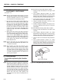
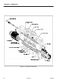
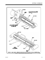
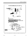
feed lines to system components can then be disconnected
with minimal fluid loss.
GENERAL
This section contains the general safety precautions which
must be observed during maintenance of the aerial platform. It is of utmost importance that maintenance personnel pay strict attention to these warnings and precautions
to avoid possible injury to themselves or others, or damage to the equipment. A maintenance program must be
followed to ensure that the machine is safe to operate.
MODIFICATION OF THE MACHINE WITHOUT CERTIFICATION BY
A RESPONSIBLE AUTHORITY THAT THE MACHINE IS AT LEAST
AS SAFE AS ORIGINALLY MANUFACTURED, IS A SAFETY VIOLATION.
The specific precautions to be observed during maintenance are inserted at the appropriate point in the manual.
These precautions are, for the most part, those that apply
when servicing hydraulic and larger machine component
parts.
Your safety, and that of others, is the first consideration
when engaging in the maintenance of equipment. Always
be conscious of weight. Never attempt to move heavy
parts without the aid of a mechanical device. Do not allow
heavy objects to rest in an unstable position. When raising
a portion of the equipment, ensure that adequate support is
provided.
SINCE THE MACHINE MANUFACTURER HAS NO DIRECT CONTROL OVER THE FIELD INSPECTION AND MAINTENANCE,
SAFETY IN THIS AREA RESPONSIBILITY OF THE OWNER/OPERATOR.
B
HYDRAULIC SYSTEM SAFETY
It should be noted that the machines hydraulic systems
operate at extremely high potentially dangerous pressures.
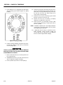
Every effort should be made to relieve any system pressure prior to disconnecting or removing any portion of the
system.
C
MAINTENANCE
FAILURE TO COMPLY WITH SAFETY PRECAUTIONS LISTED IN
THIS SECTION MAY RESULT IN MACHINE DAMAGE, PERSONNEL
INJURY OR DEATH AND IS A SAFETY VIOLATION.
• NO SMOKING IS MANDATORY. NEVER REFUEL DURING ELECTRICAL STORMS. ENSURE THAT FUEL
CAP IS CLOSED AND SECURE AT ALL OTHER
TIMES.
• REMOVE ALL RINGS, WATCHES AND JEWELRY
WHEN PERFORMING ANY MAINTENANCE.
• DO NOT WEAR LONG HAIR UNRESTRAINED, OR
LOOSE-FITTING CLOTHING AND NECKTIES WHICH
ARE APT TO BECOME CAUGHT ON OR ENTANGLED
IN EQUIPMENT.
• OBSERVE AND OBEY ALL WARNINGS AND CAUTIONS ON MACHINE AND IN SERVICEMANUAL.
• KEEP OIL, GREASE, WATER, ETC. WIPED FROM
STANDING SURFACES AND HAND HOLDS.
• USE CAUTION WHEN CHECKING A HOT, PRESSURIZED COOLANT SYSTEM.
• NEVER WORK UNDER AN ELEVATED BOOM UNTIL
BOOM HAS BEEN SAFELY RESTRAINED FROM ANY
MOVEMENT BY BLOCKING OR OVERHEAD SLING,
OR BOOM SAFETY PROP HAS BEEN ENGAGED.
• BEFORE MAKING ADJUSTMENTS, LUBRICATING OR
PERFORMING ANY OTHER MAINTENANCE, SHUT
OFF ALL POWER CONTROLS.
• BATTERY SHOULD ALWAYS BE DISCONNECTEDDURING REPLACEMENT OF ELECTRICAL COMPONENTS.
• KEEP ALL SUPPORT EQUIPMENT AND ATTACHMENTS STOWED IN THEIR PROPER PLACE.
• USE ONLY APPROVED, NONFLAMMABLE CLEANING
SOLVENTS.
Relieve system pressure by cycling the applicable control
several times with the engine stopped and ignition on, to
direct any line pressure back into the reservoir. Pressure
3120271
– JLG Lift –
A-1
INTRODUCTION
REVISON LOG
March, 1986
February, 1997
March 1, 1999
September 7, 2000
May 21, 2003
November 19, 2003
A-2
- Original Issue
- Revised
- Revised
- Revised
- Revised
- Revised
– JLG Lift –
3120271
TABLE OF CONTENTS
TABLE OF CONTENTS
SUBJECT - SECTION, PARAGRAPH
PAGE NO.
SECTION A - INTRODUCTION - MAINTENANCE SAFETY PRECAUTIONS
A
B
C
General . . . . . . . . . . . . . . . . . . . . . . . . . . . . . . . . . . . . . . . . . . . . . . . . . . . . . . . . . . . . . . . . . . . . . .A-1
Hydraulic System Safety . . . . . . . . . . . . . . . . . . . . . . . . . . . . . . . . . . . . . . . . . . . . . . . . . . . . . . . . .A-1
Maintenance . . . . . . . . . . . . . . . . . . . . . . . . . . . . . . . . . . . . . . . . . . . . . . . . . . . . . . . . . . . . . . . . . .A-1
SECTION 1 - SPECIFICATIONS
1.1
1.2
1.3
1.4
1.5
1.6
1.7
1.8
3120271
Capacities . . . . . . . . . . . . . . . . . . . . . . . . . . . . . . . . . . . . . . . . . . . . . . . . . . . . . . . . . . . . . . . . . . . .1-1
Component Data . . . . . . . . . . . . . . . . . . . . . . . . . . . . . . . . . . . . . . . . . . . . . . . . . . . . . . . . . . . . . . .1-1
Engine - Ford LSG423 . . . . . . . . . . . . . . . . . . . . . . . . . . . . . . . . . . . . . . . . . . . . . . . . . . . . . . 1-1
Engine - Deutz F4L912 . . . . . . . . . . . . . . . . . . . . . . . . . . . . . . . . . . . . . . . . . . . . . . . . . . . . . 1-1
Engine - Wisconsin V465D . . . . . . . . . . . . . . . . . . . . . . . . . . . . . . . . . . . . . . . . . . . . . . . . . . 1-1
Engine - Cummins 4B 3.9C . . . . . . . . . . . . . . . . . . . . . . . . . . . . . . . . . . . . . . . . . . . . . . . . . . 1-1
Engine - Ford LRG-423 . . . . . . . . . . . . . . . . . . . . . . . . . . . . . . . . . . . . . . . . . . . . . . . . . . . . . 1-2
Engine - Ford LRG-425 . . . . . . . . . . . . . . . . . . . . . . . . . . . . . . . . . . . . . . . . . . . . . . . . . . . . . 1-2
Drive System . . . . . . . . . . . . . . . . . . . . . . . . . . . . . . . . . . . . . . . . . . . . . . . . . . . . . . . . . . . . . 1-2
Drive Motor Displacement Machines Built Prior to Jan. 1992. . . . . . . . . . . . . . . . . . . . . . . . 1-2
Drive Motor Displacement Machines Built from Jan. 1992 to Present . . . . . . . . . . . . . . . . . 1-2
Drive Hub Ratios . . . . . . . . . . . . . . . . . . . . . . . . . . . . . . . . . . . . . . . . . . . . . . . . . . . . . . . . . . 1-2
Steer System . . . . . . . . . . . . . . . . . . . . . . . . . . . . . . . . . . . . . . . . . . . . . . . . . . . . . . . . . . . . . 1-2
Swing System . . . . . . . . . . . . . . . . . . . . . . . . . . . . . . . . . . . . . . . . . . . . . . . . . . . . . . . . . . . . 1-2
Hydraulic Pump . . . . . . . . . . . . . . . . . . . . . . . . . . . . . . . . . . . . . . . . . . . . . . . . . . . . . . . . . . 1-2
Auxiliary Power Pump. . . . . . . . . . . . . . . . . . . . . . . . . . . . . . . . . . . . . . . . . . . . . . . . . . . . . . 1-3
Hydraulic Filter - Tank. . . . . . . . . . . . . . . . . . . . . . . . . . . . . . . . . . . . . . . . . . . . . . . . . . . . . . 1-3
Hydraulic Filter - Inline (Racine Valve Only) . . . . . . . . . . . . . . . . . . . . . . . . . . . . . . . . . . . . . 1-3
Performance Data . . . . . . . . . . . . . . . . . . . . . . . . . . . . . . . . . . . . . . . . . . . . . . . . . . . . . . . . . . . . . .1-3
Travel Speed . . . . . . . . . . . . . . . . . . . . . . . . . . . . . . . . . . . . . . . . . . . . . . . . . . . . . . . . . . . . . 1-3
Gradeability . . . . . . . . . . . . . . . . . . . . . . . . . . . . . . . . . . . . . . . . . . . . . . . . . . . . . . . . . . . . . . 1-3
Turning Radius (Outside) . . . . . . . . . . . . . . . . . . . . . . . . . . . . . . . . . . . . . . . . . . . . . . . . . . . 1-3
Boom Speed (Telescope) . . . . . . . . . . . . . . . . . . . . . . . . . . . . . . . . . . . . . . . . . . . . . . . . . . . 1-3
Boom Speed (Lift) . . . . . . . . . . . . . . . . . . . . . . . . . . . . . . . . . . . . . . . . . . . . . . . . . . . . . . . . . 1-3
Swing Speed 360° . . . . . . . . . . . . . . . . . . . . . . . . . . . . . . . . . . . . . . . . . . . . . . . . . . . . . . . . . 1-3
Boom Elevation . . . . . . . . . . . . . . . . . . . . . . . . . . . . . . . . . . . . . . . . . . . . . . . . . . . . . . . . . . . 1-3
Machine Weight . . . . . . . . . . . . . . . . . . . . . . . . . . . . . . . . . . . . . . . . . . . . . . . . . . . . . . . . . . . 1-3
Machine Stowed Height . . . . . . . . . . . . . . . . . . . . . . . . . . . . . . . . . . . . . . . . . . . . . . . . . . . . 1-3
Machine Stowed Length . . . . . . . . . . . . . . . . . . . . . . . . . . . . . . . . . . . . . . . . . . . . . . . . . . . . 1-3
Machine Width . . . . . . . . . . . . . . . . . . . . . . . . . . . . . . . . . . . . . . . . . . . . . . . . . . . . . . . . . . . . 1-3
Maximum Tire Load . . . . . . . . . . . . . . . . . . . . . . . . . . . . . . . . . . . . . . . . . . . . . . . . . . . . . . . . 1-3
Wheelbase . . . . . . . . . . . . . . . . . . . . . . . . . . . . . . . . . . . . . . . . . . . . . . . . . . . . . . . . . . . . . . . 1-3
Torque Requirements . . . . . . . . . . . . . . . . . . . . . . . . . . . . . . . . . . . . . . . . . . . . . . . . . . . . . . . . . . .1-4
Lubrication. . . . . . . . . . . . . . . . . . . . . . . . . . . . . . . . . . . . . . . . . . . . . . . . . . . . . . . . . . . . . . . . . . . .1-4
Ford Engines. . . . . . . . . . . . . . . . . . . . . . . . . . . . . . . . . . . . . . . . . . . . . . . . . . . . . . . . . . . . . 1-9
Deutz F4L912 Engine . . . . . . . . . . . . . . . . . . . . . . . . . . . . . . . . . . . . . . . . . . . . . . . . . . . . . . 1-9
Wisconsin V465D Engine . . . . . . . . . . . . . . . . . . . . . . . . . . . . . . . . . . . . . . . . . . . . . . . . . . . 1-9
Cummins 4B 3.9C. . . . . . . . . . . . . . . . . . . . . . . . . . . . . . . . . . . . . . . . . . . . . . . . . . . . . . . . . 1-9
Lubrication Specifications . . . . . . . . . . . . . . . . . . . . . . . . . . . . . . . . . . . . . . . . . . . . . . . . . . . 1-10
Pressure Settings . . . . . . . . . . . . . . . . . . . . . . . . . . . . . . . . . . . . . . . . . . . . . . . . . . . . . . . . . . . . . .1-10
Prior to Mid 1987. . . . . . . . . . . . . . . . . . . . . . . . . . . . . . . . . . . . . . . . . . . . . . . . . . . . . . . . . . 1-10
80 HX. . . . . . . . . . . . . . . . . . . . . . . . . . . . . . . . . . . . . . . . . . . . . . . . . . . . . . . . . . . . . . . . . . . 1-11
80HX w/Hydraulic Controls. . . . . . . . . . . . . . . . . . . . . . . . . . . . . . . . . . . . . . . . . . . . . . . . . . 1-11
80HX w/Oscillating Axle . . . . . . . . . . . . . . . . . . . . . . . . . . . . . . . . . . . . . . . . . . . . . . . . . . . . 1-11
Major Components Weights . . . . . . . . . . . . . . . . . . . . . . . . . . . . . . . . . . . . . . . . . . . . . . . . . . . . . .1-12
Cylinder Specifications . . . . . . . . . . . . . . . . . . . . . . . . . . . . . . . . . . . . . . . . . . . . . . . . . . . . . . . . . .1-12
– JLG Lift –
i
TABLE OF CONTENTS (Continued)
TABLE OF CONTENTS (continued)
SUBJECT - SECTION, PARAGRAPH
1.9
1.10
1.11
PAGE NO.
Boom Tape . . . . . . . . . . . . . . . . . . . . . . . . . . . . . . . . . . . . . . . . . . . . . . . . . . . . . . . . . . . . . . . . . . .1-12
American Standard . . . . . . . . . . . . . . . . . . . . . . . . . . . . . . . . . . . . . . . . . . . . . . . . . . . . . . . . 1-12
Canadian Standard. . . . . . . . . . . . . . . . . . . . . . . . . . . . . . . . . . . . . . . . . . . . . . . . . . . . . . . . 1-12
Critical Stability Weights . . . . . . . . . . . . . . . . . . . . . . . . . . . . . . . . . . . . . . . . . . . . . . . . . . . . . . . . .1-13
Serial Number Location. . . . . . . . . . . . . . . . . . . . . . . . . . . . . . . . . . . . . . . . . . . . . . . . . . . . . . . . . .1-13
SECTION 2 - GENERAL
2.1
2.2
2.3
2.4
2.5
2.6
2.7
2.8
Machine Preparation, Inspection, and Maintenance . . . . . . . . . . . . . . . . . . . . . . . . . . . . . . . . . . .2-1
General . . . . . . . . . . . . . . . . . . . . . . . . . . . . . . . . . . . . . . . . . . . . . . . . . . . . . . . . . . . . . . . . . 2-1
Preparation, Inspection, and Maintenance . . . . . . . . . . . . . . . . . . . . . . . . . . . . . . . . . . . . . . 2-1
Pre-Start Inspection . . . . . . . . . . . . . . . . . . . . . . . . . . . . . . . . . . . . . . . . . . . . . . . . . . . . . . . . 2-1
Pre-Delivery Inspection and Frequent Inspection . . . . . . . . . . . . . . . . . . . . . . . . . . . . . . . . . 2-1
Annual Machine Inspection . . . . . . . . . . . . . . . . . . . . . . . . . . . . . . . . . . . . . . . . . . . . . . . . . . 2-1
Preventative Maintenance . . . . . . . . . . . . . . . . . . . . . . . . . . . . . . . . . . . . . . . . . . . . . . . . . . . 2-1
Service and Guidelines . . . . . . . . . . . . . . . . . . . . . . . . . . . . . . . . . . . . . . . . . . . . . . . . . . . . . . . . . .2-2
General . . . . . . . . . . . . . . . . . . . . . . . . . . . . . . . . . . . . . . . . . . . . . . . . . . . . . . . . . . . . . . . . . 2-2
Safety and Workmanship . . . . . . . . . . . . . . . . . . . . . . . . . . . . . . . . . . . . . . . . . . . . . . . . . . . 2-2
Cleanliness. . . . . . . . . . . . . . . . . . . . . . . . . . . . . . . . . . . . . . . . . . . . . . . . . . . . . . . . . . . . . . . 2-2
Components Removal and Installation . . . . . . . . . . . . . . . . . . . . . . . . . . . . . . . . . . . . . . . . . 2-2
Component Disassembly and Reassembly . . . . . . . . . . . . . . . . . . . . . . . . . . . . . . . . . . . . . 2-3
Pressure-Fit Parts . . . . . . . . . . . . . . . . . . . . . . . . . . . . . . . . . . . . . . . . . . . . . . . . . . . . . . . . . 2-3
Bearings. . . . . . . . . . . . . . . . . . . . . . . . . . . . . . . . . . . . . . . . . . . . . . . . . . . . . . . . . . . . . . . . . 2-3
Gaskets . . . . . . . . . . . . . . . . . . . . . . . . . . . . . . . . . . . . . . . . . . . . . . . . . . . . . . . . . . . . . . . . . 2-3
Bolt Usage and Torque Application . . . . . . . . . . . . . . . . . . . . . . . . . . . . . . . . . . . . . . . . . . . 2-3
Hydraulic Lines and Electrical Wiring . . . . . . . . . . . . . . . . . . . . . . . . . . . . . . . . . . . . . . . . . . 2-3
Hydraulic System. . . . . . . . . . . . . . . . . . . . . . . . . . . . . . . . . . . . . . . . . . . . . . . . . . . . . . . . . . 2-3
Lubrication . . . . . . . . . . . . . . . . . . . . . . . . . . . . . . . . . . . . . . . . . . . . . . . . . . . . . . . . . . . . . . . 2-3
Battery . . . . . . . . . . . . . . . . . . . . . . . . . . . . . . . . . . . . . . . . . . . . . . . . . . . . . . . . . . . . . . . . . . 2-3
Lubrication and Servicing . . . . . . . . . . . . . . . . . . . . . . . . . . . . . . . . . . . . . . . . . . . . . . . . . . . 2-3
Lubrication and Information . . . . . . . . . . . . . . . . . . . . . . . . . . . . . . . . . . . . . . . . . . . . . . . . . . . . . .2-4
Hydraulic System. . . . . . . . . . . . . . . . . . . . . . . . . . . . . . . . . . . . . . . . . . . . . . . . . . . . . . . . . . 2-4
Hydraulic Oil . . . . . . . . . . . . . . . . . . . . . . . . . . . . . . . . . . . . . . . . . . . . . . . . . . . . . . . . . . . . . 2-4
Changing Hydraulic Oil . . . . . . . . . . . . . . . . . . . . . . . . . . . . . . . . . . . . . . . . . . . . . . . . . . . . . 2-4
Lubrication Specifications . . . . . . . . . . . . . . . . . . . . . . . . . . . . . . . . . . . . . . . . . . . . . . . . . . . 2-4
Cylinder Drift Test . . . . . . . . . . . . . . . . . . . . . . . . . . . . . . . . . . . . . . . . . . . . . . . . . . . . . . . . . . . . . .2-5
Platform Drift . . . . . . . . . . . . . . . . . . . . . . . . . . . . . . . . . . . . . . . . . . . . . . . . . . . . . . . . . . . . . 2-5
Cylinder Drift . . . . . . . . . . . . . . . . . . . . . . . . . . . . . . . . . . . . . . . . . . . . . . . . . . . . . . . . . . . . . 2-5
Pins and Composite Bearing Repair Guidelines . . . . . . . . . . . . . . . . . . . . . . . . . . . . . . . . . . . . . .2-5
Welding on JLG Equipment . . . . . . . . . . . . . . . . . . . . . . . . . . . . . . . . . . . . . . . . . . . . . . . . . . . . . .2-6
Do the Following When Welding on JLG Equipment . . . . . . . . . . . . . . . . . . . . . . . . . . . . . . 2-6
Do NOT Do the Following When Welding on JLG Equipment . . . . . . . . . . . . . . . . . . . . . . . 2-6
Applying Silicone Dielectric Compound to Electrical Connections . . . . . . . . . . . . . . . . . . . . . . . .2-6
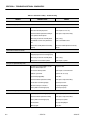
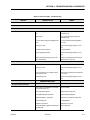
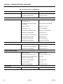
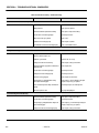
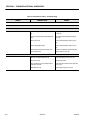
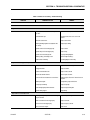
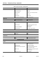
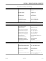
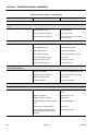
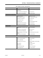
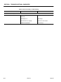
Preventive Maintenance and Inspection Schedule . . . . . . . . . . . . . . . . . . . . . . . . . . . . . . . . . . . .2-7
SECTION 3 - CHASSIS & TURNTABLE
3.1
ii
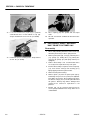
Torque Hub . . . . . . . . . . . . . . . . . . . . . . . . . . . . . . . . . . . . . . . . . . . . . . . . . . . . . . . . . . . . . . . . . . .3-1
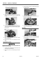
Disassembly. . . . . . . . . . . . . . . . . . . . . . . . . . . . . . . . . . . . . . . . . . . . . . . . . . . . . . . . . . . . . . 3-1
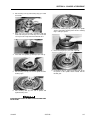
Cleaning and Inspection . . . . . . . . . . . . . . . . . . . . . . . . . . . . . . . . . . . . . . . . . . . . . . . . . . . . 3-1
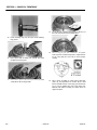
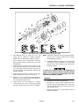
Repair. . . . . . . . . . . . . . . . . . . . . . . . . . . . . . . . . . . . . . . . . . . . . . . . . . . . . . . . . . . . . . . . . . . 3-3
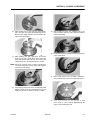
Input Shaft Assembly. . . . . . . . . . . . . . . . . . . . . . . . . . . . . . . . . . . . . . . . . . . . . . . . . . . . . . . 3-4
Assembly . . . . . . . . . . . . . . . . . . . . . . . . . . . . . . . . . . . . . . . . . . . . . . . . . . . . . . . . . . . . . . . . 3-4
– JLG Lift –
3120271
TABLE OF CONTENTS
TABLE OF CONTENTS (continued)
SUBJECT - SECTION, PARAGRAPH
3.2
3.3
3.4
3.5
3.6
3.7
3.8
3.9
3.10
3.11
3.12
3.13
3.14
3.15
3.16
3.17
3120271
PAGE NO.
Drive Brake, Ausco - Machines Built Prior to October 1987. . . . . . . . . . . . . . . . . . . . . . . . . . . . . .3-8
Disassembly. . . . . . . . . . . . . . . . . . . . . . . . . . . . . . . . . . . . . . . . . . . . . . . . . . . . . . . . . . . . . . 3-8
Cleaning and Inspection . . . . . . . . . . . . . . . . . . . . . . . . . . . . . . . . . . . . . . . . . . . . . . . . . . . . 3-9
Assembly . . . . . . . . . . . . . . . . . . . . . . . . . . . . . . . . . . . . . . . . . . . . . . . . . . . . . . . . . . . . . . . . 3-9
Drive Brake, Mico - Machines Built Prior to October 1987 . . . . . . . . . . . . . . . . . . . . . . . . . . . . . . .3-10
Disassembly. . . . . . . . . . . . . . . . . . . . . . . . . . . . . . . . . . . . . . . . . . . . . . . . . . . . . . . . . . . . . . 3-10
Inspection . . . . . . . . . . . . . . . . . . . . . . . . . . . . . . . . . . . . . . . . . . . . . . . . . . . . . . . . . . . . . . . 3-10
Assembly . . . . . . . . . . . . . . . . . . . . . . . . . . . . . . . . . . . . . . . . . . . . . . . . . . . . . . . . . . . . . . . . 3-10
Bleeding . . . . . . . . . . . . . . . . . . . . . . . . . . . . . . . . . . . . . . . . . . . . . . . . . . . . . . . . . . . . . . . . . 3-11
Drive Brake, Ausco - Machines Built Prior to 1992 . . . . . . . . . . . . . . . . . . . . . . . . . . . . . . . . . . . . .3-12
Disassembly. . . . . . . . . . . . . . . . . . . . . . . . . . . . . . . . . . . . . . . . . . . . . . . . . . . . . . . . . . . . . . 3-12
Cleaning and Inspection . . . . . . . . . . . . . . . . . . . . . . . . . . . . . . . . . . . . . . . . . . . . . . . . . . . . 3-12
Assembly . . . . . . . . . . . . . . . . . . . . . . . . . . . . . . . . . . . . . . . . . . . . . . . . . . . . . . . . . . . . . . . . 3-12
Drive Brake, Mico - Machines Built From 1992 to Present . . . . . . . . . . . . . . . . . . . . . . . . . . . . . . .3-14
Disassembly. . . . . . . . . . . . . . . . . . . . . . . . . . . . . . . . . . . . . . . . . . . . . . . . . . . . . . . . . . . . . . 3-14
Inspection . . . . . . . . . . . . . . . . . . . . . . . . . . . . . . . . . . . . . . . . . . . . . . . . . . . . . . . . . . . . . . . 3-14
Assembly . . . . . . . . . . . . . . . . . . . . . . . . . . . . . . . . . . . . . . . . . . . . . . . . . . . . . . . . . . . . . . . . 3-14
Governor Checks and Adeco Adjustment, LRG423 & LRG425 . . . . . . . . . . . . . . . . . . . . . . . . . . .3-17
Checks . . . . . . . . . . . . . . . . . . . . . . . . . . . . . . . . . . . . . . . . . . . . . . . . . . . . . . . . . . . . . . . . . . 3-17
Adjustments . . . . . . . . . . . . . . . . . . . . . . . . . . . . . . . . . . . . . . . . . . . . . . . . . . . . . . . . . . . . . . 3-17
Throttle Checks and Precision Governor Adjustments, LSG-423 & LRG-425 . . . . . . . . . . . . . . . .3-22
Checks . . . . . . . . . . . . . . . . . . . . . . . . . . . . . . . . . . . . . . . . . . . . . . . . . . . . . . . . . . . . . . . . . . 3-22
Carburetor and Governor Adjustment. . . . . . . . . . . . . . . . . . . . . . . . . . . . . . . . . . . . . . . . . . 3-22
E331 Precision Governor And Adjustments - Ford Engines . . . . . . . . . . . . . . . . . . . . . . . . . . . . .3-23
General. . . . . . . . . . . . . . . . . . . . . . . . . . . . . . . . . . . . . . . . . . . . . . . . . . . . . . . . . . . . . . . . . . 3-23
Quick-start Installations . . . . . . . . . . . . . . . . . . . . . . . . . . . . . . . . . . . . . . . . . . . . . . . . . . . . . 3-23
Mounting-Actuator . . . . . . . . . . . . . . . . . . . . . . . . . . . . . . . . . . . . . . . . . . . . . . . . . . . . . . . . . 3-24
Linkage. . . . . . . . . . . . . . . . . . . . . . . . . . . . . . . . . . . . . . . . . . . . . . . . . . . . . . . . . . . . . . . . . . 3-24
Mounting-Controller. . . . . . . . . . . . . . . . . . . . . . . . . . . . . . . . . . . . . . . . . . . . . . . . . . . . . . . . 3-25
Wiring . . . . . . . . . . . . . . . . . . . . . . . . . . . . . . . . . . . . . . . . . . . . . . . . . . . . . . . . . . . . . . . . . . . 3-25
Power Distribution . . . . . . . . . . . . . . . . . . . . . . . . . . . . . . . . . . . . . . . . . . . . . . . . . . . . . . . . . 3-25
Check-Out and Initial Start-Up Procedures . . . . . . . . . . . . . . . . . . . . . . . . . . . . . . . . . . . . . . 3-26
Troubleshooting. . . . . . . . . . . . . . . . . . . . . . . . . . . . . . . . . . . . . . . . . . . . . . . . . . . . . . . . . . . 3-29
Automatic Choke Adjustment Procedure . . . . . . . . . . . . . . . . . . . . . . . . . . . . . . . . . . . . . . . 3-31
Automatic Choke Adjustment - Ford Engine . . . . . . . . . . . . . . . . . . . . . . . . . . . . . . . . . . . . . . . . .3-31
Cold Weather Starting Difficulty . . . . . . . . . . . . . . . . . . . . . . . . . . . . . . . . . . . . . . . . . . . . . . . . . . .3-32
Checking the Carburetor . . . . . . . . . . . . . . . . . . . . . . . . . . . . . . . . . . . . . . . . . . . . . . . . . . . . 3-32
Checking the Ignition. . . . . . . . . . . . . . . . . . . . . . . . . . . . . . . . . . . . . . . . . . . . . . . . . . . . . . . 3-33
Checking the Fuel . . . . . . . . . . . . . . . . . . . . . . . . . . . . . . . . . . . . . . . . . . . . . . . . . . . . . . . . . 3-33
Throttle Checks and Adjustments - Deutz Engine . . . . . . . . . . . . . . . . . . . . . . . . . . . . . . . . . . . . .3-34
Swing Bearing . . . . . . . . . . . . . . . . . . . . . . . . . . . . . . . . . . . . . . . . . . . . . . . . . . . . . . . . . . . . . . . . .3-34
Turntable Bearing Mounting Bolt Condition Check . . . . . . . . . . . . . . . . . . . . . . . . . . . . . . . 3-34
Wear Tolerance . . . . . . . . . . . . . . . . . . . . . . . . . . . . . . . . . . . . . . . . . . . . . . . . . . . . . . . . . . . 3-35
Replacement and Devcon Application Procedures on Machines Built Prior to Mid 1991 . . 3-35
Swing Bearing Torque Values . . . . . . . . . . . . . . . . . . . . . . . . . . . . . . . . . . . . . . . . . . . . . . . . 3-39
Oscillating Axle Bleeding Procedure. . . . . . . . . . . . . . . . . . . . . . . . . . . . . . . . . . . . . . . . . . . . . . . .3-40
Lockout Cylinder Bleeding (Without Holding Valves) . . . . . . . . . . . . . . . . . . . . . . . . . . . . . . 3-40
Lockout Cylinder Bleeding (With Holding Valves) . . . . . . . . . . . . . . . . . . . . . . . . . . . . . . . . 3-40
Oscillating Axle Lockout Test . . . . . . . . . . . . . . . . . . . . . . . . . . . . . . . . . . . . . . . . . . . . . . . . . . . . .3-41
Free Wheeling Option . . . . . . . . . . . . . . . . . . . . . . . . . . . . . . . . . . . . . . . . . . . . . . . . . . . . . . . . . . .3-41
To Disengage Drive Motors and Brakes (Free Wheel) for Towing, etc. . . . . . . . . . . . . . . . . 3-41
To Engage Drive Motors and Brakes (Normal Operation) . . . . . . . . . . . . . . . . . . . . . . . . . . 3-41
Spark Arrestor Mufflers . . . . . . . . . . . . . . . . . . . . . . . . . . . . . . . . . . . . . . . . . . . . . . . . . . . . . . . . . .3-42
Footswitch Adjustment . . . . . . . . . . . . . . . . . . . . . . . . . . . . . . . . . . . . . . . . . . . . . . . . . . . . . . . . . .3-42
– JLG Lift –
iii
TABLE OF CONTENTS (Continued)
TABLE OF CONTENTS (continued)
SUBJECT - SECTION, PARAGRAPH
3.18
3.19
PAGE NO.
Hydraulic Pump W/Hayes Pump Drive Coupling Lubrication . . . . . . . . . . . . . . . . . . . . . . . . . . . .3-42
Dual Fuel System . . . . . . . . . . . . . . . . . . . . . . . . . . . . . . . . . . . . . . . . . . . . . . . . . . . . . . . . . . . . . .3-42
Changing from gasoline to LP-Gas . . . . . . . . . . . . . . . . . . . . . . . . . . . . . . . . . . . . . . . . . . . . 3-42
Changing from LP Gas to Gasoline. . . . . . . . . . . . . . . . . . . . . . . . . . . . . . . . . . . . . . . . . . . . 3-42
SECTION 4 - BOOM & PLATFORM
4.1
4.2
4.3
4.4
4.5
4.6
4.7
4.8
Boom Maintenance . . . . . . . . . . . . . . . . . . . . . . . . . . . . . . . . . . . . . . . . . . . . . . . . . . . . . . . . . . . . .4-1
Removal . . . . . . . . . . . . . . . . . . . . . . . . . . . . . . . . . . . . . . . . . . . . . . . . . . . . . . . . . . . . . . . . . 4-1
Disassembly. . . . . . . . . . . . . . . . . . . . . . . . . . . . . . . . . . . . . . . . . . . . . . . . . . . . . . . . . . . . . . 4-1
Inspection . . . . . . . . . . . . . . . . . . . . . . . . . . . . . . . . . . . . . . . . . . . . . . . . . . . . . . . . . . . . . . . 4-4
Assembly . . . . . . . . . . . . . . . . . . . . . . . . . . . . . . . . . . . . . . . . . . . . . . . . . . . . . . . . . . . . . . . . 4-5
Installation . . . . . . . . . . . . . . . . . . . . . . . . . . . . . . . . . . . . . . . . . . . . . . . . . . . . . . . . . . . . . . . 4-6
Boom Chains. . . . . . . . . . . . . . . . . . . . . . . . . . . . . . . . . . . . . . . . . . . . . . . . . . . . . . . . . . . . . . . . . .4-7
Adjusting Procedures . . . . . . . . . . . . . . . . . . . . . . . . . . . . . . . . . . . . . . . . . . . . . . . . . . . . . . 4-7
Inspection Procedures. . . . . . . . . . . . . . . . . . . . . . . . . . . . . . . . . . . . . . . . . . . . . . . . . . . . . . 4-8
Wear Pads . . . . . . . . . . . . . . . . . . . . . . . . . . . . . . . . . . . . . . . . . . . . . . . . . . . . . . . . . . . . . . . . . . . .4-10
Telescope Cylinder Eccentric Bushing. . . . . . . . . . . . . . . . . . . . . . . . . . . . . . . . . . . . . . . . . . . . . .4-10
Horizontal High Speed Cutout Switch Adjustment Procedure. . . . . . . . . . . . . . . . . . . . . . . . . . . .4-10
Controllers . . . . . . . . . . . . . . . . . . . . . . . . . . . . . . . . . . . . . . . . . . . . . . . . . . . . . . . . . . . . . . . . . . . .4-10
PQ . . . . . . . . . . . . . . . . . . . . . . . . . . . . . . . . . . . . . . . . . . . . . . . . . . . . . . . . . . . . . . . . . . . . . 4-10
OEM . . . . . . . . . . . . . . . . . . . . . . . . . . . . . . . . . . . . . . . . . . . . . . . . . . . . . . . . . . . . . . . . . . . . 4-10
VICKERS (All Hydraulic) . . . . . . . . . . . . . . . . . . . . . . . . . . . . . . . . . . . . . . . . . . . . . . . . . . . . 4-10
Capacity Indicator . . . . . . . . . . . . . . . . . . . . . . . . . . . . . . . . . . . . . . . . . . . . . . . . . . . . . . . . . . . . . .4-10
Capacity Indicator Cable Adjustment . . . . . . . . . . . . . . . . . . . . . . . . . . . . . . . . . . . . . . . . . . 4-10
Capacity Indicator Boom Tape Replacement . . . . . . . . . . . . . . . . . . . . . . . . . . . . . . . . . . . . 4-11
Installation Procedure . . . . . . . . . . . . . . . . . . . . . . . . . . . . . . . . . . . . . . . . . . . . . . . . . . . . . . 4-11
Capacity Indicator Dial Decal Replacement . . . . . . . . . . . . . . . . . . . . . . . . . . . . . . . . . . . . . 4-11
Indicator Decal Installation . . . . . . . . . . . . . . . . . . . . . . . . . . . . . . . . . . . . . . . . . . . . . . . . . . 4-11
Basket Rotator Brake . . . . . . . . . . . . . . . . . . . . . . . . . . . . . . . . . . . . . . . . . . . . . . . . . . . . . . . . . . .4-11
SECTION 5 - HYDRAULICS
5.1
5.2
5.3
5.4
5.5
iv
Cylinders - Theory Of Operation . . . . . . . . . . . . . . . . . . . . . . . . . . . . . . . . . . . . . . . . . . . . . . . . . . .5-1
Double Acting Cylinders . . . . . . . . . . . . . . . . . . . . . . . . . . . . . . . . . . . . . . . . . . . . . . . . . . . . 5-1
Valves - Theory Of Operation . . . . . . . . . . . . . . . . . . . . . . . . . . . . . . . . . . . . . . . . . . . . . . . . . . . . .5-1
Holding Valves . . . . . . . . . . . . . . . . . . . . . . . . . . . . . . . . . . . . . . . . . . . . . . . . . . . . . . . . . . . . 5-1
Solenoid Control Valves (Bang-Bang) . . . . . . . . . . . . . . . . . . . . . . . . . . . . . . . . . . . . . . . . . 5-1
Proportional Control Valve - Vickers . . . . . . . . . . . . . . . . . . . . . . . . . . . . . . . . . . . . . . . . . . . 5-1
Main Relief Valves . . . . . . . . . . . . . . . . . . . . . . . . . . . . . . . . . . . . . . . . . . . . . . . . . . . . . . . . . 5-1
Relief Valves. . . . . . . . . . . . . . . . . . . . . . . . . . . . . . . . . . . . . . . . . . . . . . . . . . . . . . . . . . . . . . 5-1
Cylinder Checking Procedure. . . . . . . . . . . . . . . . . . . . . . . . . . . . . . . . . . . . . . . . . . . . . . . . . . . . .5-3
Cylinders Without Counterbalance Valves . . . . . . . . . . . . . . . . . . . . . . . . . . . . . . . . . . . . . . 5-3
Cylinders With Single Counterbalance Valve . . . . . . . . . . . . . . . . . . . . . . . . . . . . . . . . . . . . 5-3
Cylinders With Dual Counterbalance Valves. . . . . . . . . . . . . . . . . . . . . . . . . . . . . . . . . . . . . 5-4
Cylinder Repair . . . . . . . . . . . . . . . . . . . . . . . . . . . . . . . . . . . . . . . . . . . . . . . . . . . . . . . . . . . . . . . .5-4
Disassembly. . . . . . . . . . . . . . . . . . . . . . . . . . . . . . . . . . . . . . . . . . . . . . . . . . . . . . . . . . . . . . 5-4
Cleaning and Inspection . . . . . . . . . . . . . . . . . . . . . . . . . . . . . . . . . . . . . . . . . . . . . . . . . . . . 5-11
Assembly . . . . . . . . . . . . . . . . . . . . . . . . . . . . . . . . . . . . . . . . . . . . . . . . . . . . . . . . . . . . . . . 5-12
Cylinder Removal and Installation . . . . . . . . . . . . . . . . . . . . . . . . . . . . . . . . . . . . . . . . . . . . . . . . .5-14
Telescope Cylinder Removal . . . . . . . . . . . . . . . . . . . . . . . . . . . . . . . . . . . . . . . . . . . . . . . . 5-14
Telescope Cylinder Installation . . . . . . . . . . . . . . . . . . . . . . . . . . . . . . . . . . . . . . . . . . . . . . 5-14
Boom Lift Cylinder Removal . . . . . . . . . . . . . . . . . . . . . . . . . . . . . . . . . . . . . . . . . . . . . . . . . 5-15
Boom Lift Cylinder Installation . . . . . . . . . . . . . . . . . . . . . . . . . . . . . . . . . . . . . . . . . . . . . . . 5-15
– JLG Lift –
3120271
TABLE OF CONTENTS
TABLE OF CONTENTS (continued)
SUBJECT - SECTION, PARAGRAPH
5.6
5.7
5.8
5.9
PAGE NO.
Telescope Cylinder Eccentric Bushing . . . . . . . . . . . . . . . . . . . . . . . . . . . . . . . . . . . . . . . . . . . . . .5-15
Hydraulic Pump W/Hayes Pump Drive Coupling Lubrication . . . . . . . . . . . . . . . . . . . . . . . . . . . .5-15
Racine Proportional Air Gap Adjustment . . . . . . . . . . . . . . . . . . . . . . . . . . . . . . . . . . . . . . . . . . . .5-16
Pressure Setting Procedures . . . . . . . . . . . . . . . . . . . . . . . . . . . . . . . . . . . . . . . . . . . . . . . . . . . . .5-16
SECTION 6 - TROUBLESHOOTING & SCHEMATICS
6.1
6.2
6.3
General . . . . . . . . . . . . . . . . . . . . . . . . . . . . . . . . . . . . . . . . . . . . . . . . . . . . . . . . . . . . . . . . . . . . . .6-1
Troubleshooting Information. . . . . . . . . . . . . . . . . . . . . . . . . . . . . . . . . . . . . . . . . . . . . . . . . . . . . .6-1
Hydraulic Circuit Checks. . . . . . . . . . . . . . . . . . . . . . . . . . . . . . . . . . . . . . . . . . . . . . . . . . . . . . . . .6-1
LIST OF FIGURES
FIGURE NO.
1-1.
1-2.
1-3.
1-4.
1-5.
3-1.
3-2.
3-3.
3-4.
3-5.
3-6.
3-7.
3-8.
3-9.
3-10.
3-11.
3-12.
3-13.
3-14.
3-15.
4-1.
4-2.
4-3.
4-4.
4-5.
4-6.
4-7.
5-1.
5-2.
5-3.
5-4.
5-5.
5-6.
5-7.
5-8.
5-9.
5-10.
5-11.
5-12.
5-13.
3120271
TITLE
PAGE NO.
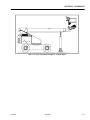
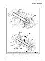
Lubrication Diagram . . . . . . . . . . . . . . . . . . . . . . . . . . . . . . . . . . . . . . . . . . . . . . . . . . . . . . . . . . . .1-5
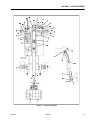
Serial Number Locations. . . . . . . . . . . . . . . . . . . . . . . . . . . . . . . . . . . . . . . . . . . . . . . . . . . . . . . . .1-13
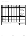
Torque Chart - (In/Lb - Ft/Lb). (For ASTM Fasteners) . . . . . . . . . . . . . . . . . . . . . . . . . . . . . . . . . .1-14
Torque Chart (Metric Conversion) - (For ASTM Fasteners) . . . . . . . . . . . . . . . . . . . . . . . . . . . . . .1-15
Torque Chart - (N, m) - (For Metric Class Fasteners). . . . . . . . . . . . . . . . . . . . . . . . . . . . . . . . . . .1-16
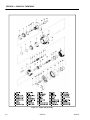
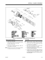
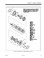
Torque Hub Assembly. . . . . . . . . . . . . . . . . . . . . . . . . . . . . . . . . . . . . . . . . . . . . . . . . . . . . . . . . . .3-2
Drive Brake, Ausco - Machines Built Prior to October 1987. . . . . . . . . . . . . . . . . . . . . . . . . . . . . .3-9
Drive Brake, Mico - Machines Built Prior to October 1987 . . . . . . . . . . . . . . . . . . . . . . . . . . . . . . .3-11
Drive Brake, Ausco - Machines Built Prior to 1992 . . . . . . . . . . . . . . . . . . . . . . . . . . . . . . . . . . . . .3-13
Drive Brake, Mico - Machines Built from 1992 to Present . . . . . . . . . . . . . . . . . . . . . . . . . . . . . . .3-15
Spring Loading . . . . . . . . . . . . . . . . . . . . . . . . . . . . . . . . . . . . . . . . . . . . . . . . . . . . . . . . . . . . . . . .3-16
Governor Adjustment, LRG-423 & LRG-425 with Adeco . . . . . . . . . . . . . . . . . . . . . . . . . . . . . . . .3-17
Adeco Adjustment, LRG-423 & LRG-425 . . . . . . . . . . . . . . . . . . . . . . . . . . . . . . . . . . . . . . . . . . . .3-18
Precision Governor Adjustment - LRG-423 & LRG-425 (Sheet 1 of 2) . . . . . . . . . . . . . . . . . . . . . .3-19
Precision Governor Adjustment - LRG-423 & LRG-425 (Sheet 2 of 2) . . . . . . . . . . . . . . . . . . . . . .3-20
Adeco Actuator Adjustments - F4L912 . . . . . . . . . . . . . . . . . . . . . . . . . . . . . . . . . . . . . . . . . . . . . .3-21
Swing Bearing Bolt Feeler Gauge Check . . . . . . . . . . . . . . . . . . . . . . . . . . . . . . . . . . . . . . . . . . . .3-34
Swing Bearing Tolerance Measuring Point. . . . . . . . . . . . . . . . . . . . . . . . . . . . . . . . . . . . . . . . . . .3-35
Swing Bearing Tolerance Boom Placement . . . . . . . . . . . . . . . . . . . . . . . . . . . . . . . . . . . . . . . . . .3-37
Swing Bearing Torquing Sequence . . . . . . . . . . . . . . . . . . . . . . . . . . . . . . . . . . . . . . . . . . . . . . . .3-38
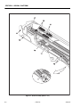
Boom Assembly (Sheet 1 of 2) . . . . . . . . . . . . . . . . . . . . . . . . . . . . . . . . . . . . . . . . . . . . . . . . . . . .4-2
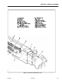
Boom Assembly (Sheet 2 of 2) . . . . . . . . . . . . . . . . . . . . . . . . . . . . . . . . . . . . . . . . . . . . . . . . . . . .4-3
Typical Boom Assembly . . . . . . . . . . . . . . . . . . . . . . . . . . . . . . . . . . . . . . . . . . . . . . . . . . . . . . . . .4-7
Telescope Cylinder Eccentric Bushing . . . . . . . . . . . . . . . . . . . . . . . . . . . . . . . . . . . . . . . . . . . . . .4-10
Boom Tape Replacement . . . . . . . . . . . . . . . . . . . . . . . . . . . . . . . . . . . . . . . . . . . . . . . . . . . . . . . .4-11
Capacity Indicator Dial . . . . . . . . . . . . . . . . . . . . . . . . . . . . . . . . . . . . . . . . . . . . . . . . . . . . . . . . . .4-11
Belleville Washers . . . . . . . . . . . . . . . . . . . . . . . . . . . . . . . . . . . . . . . . . . . . . . . . . . . . . . . . . . . . . .4-11
Proportional Control Valve . . . . . . . . . . . . . . . . . . . . . . . . . . . . . . . . . . . . . . . . . . . . . . . . . . . . . . .5-2
Boom Positioning and Support - Cylinder Repair . . . . . . . . . . . . . . . . . . . . . . . . . . . . . . . . . . . . .5-5
Typical Hydraulic Cylinders (Sheet 1 of 4) . . . . . . . . . . . . . . . . . . . . . . . . . . . . . . . . . . . . . . . . . . .5-6
Typical Hydraulic Cylinders (Sheet 2 of 4) . . . . . . . . . . . . . . . . . . . . . . . . . . . . . . . . . . . . . . . . . . .5-7
Typical Hydraulic Cylinders (Sheet 3 of 4) . . . . . . . . . . . . . . . . . . . . . . . . . . . . . . . . . . . . . . . . . . .5-8
Typical Hydraulic Cylinders (Sheet 4 of 4) . . . . . . . . . . . . . . . . . . . . . . . . . . . . . . . . . . . . . . . . . . .5-9
Cylinder Barrel Support. . . . . . . . . . . . . . . . . . . . . . . . . . . . . . . . . . . . . . . . . . . . . . . . . . . . . . . . . .5-10
Cylinder Rod Support . . . . . . . . . . . . . . . . . . . . . . . . . . . . . . . . . . . . . . . . . . . . . . . . . . . . . . . . . . .5-10
Poly-Pak Seal Installation . . . . . . . . . . . . . . . . . . . . . . . . . . . . . . . . . . . . . . . . . . . . . . . . . . . . . . . .5-12
Telescope Cylinder Eccentric Bushing . . . . . . . . . . . . . . . . . . . . . . . . . . . . . . . . . . . . . . . . . . . . . .5-15
Racine Proportional Air Gap Adjustment, Machines Built Prior to Mid 1987 . . . . . . . . . . . . . . . . .5-16
Racine Proportional Valve Pressure Setting - Prior to Mid 1987 (Sheet 1 of 2) . . . . . . . . . . . . . . .5-17
Racine Proportional Valve Pressure Setting - Prior to Mid 1987 (Sheet 2 of 2) . . . . . . . . . . . . . . .5-18
– JLG Lift –
v
TABLE OF CONTENTS (Continued)
LIST OF FIGURES (continued)
FIGURE NO.
5-14.
5-15.
5-16.
5-17.
5-18.
5-19.
5-20.
5-21.
5-22.
5-23.
5-24.
5-25.
5-26.
5-27.
5-28.
5-29.
5-30.
6-1.
6-2.
6-3.
6-4.
6-5.
6-6.
6-7.
6-8.
6-9.
6-10.
6-11.
6-12.
6-13.
6-14.
6-15.
6-16.
6-17.
6-18.
6-19.
6-20.
6-21.
6-22.
6-23.
6-24.
vi
TITLE
PAGE NO.
Vickers Proportional Valve Pressure Setting - Prior to 1989 with Accessory Valve (Sheet 1 of 4) 5-19
Vickers Proportional Valve Pressure Setting - Prior to 1989 with Accessory Valve (Sheet 2 of 4) 5-20
Vickers Proportional Valve Pressure Setting - Prior to 1989 with Accessory Valve (Sheet 3 of 4) 5-21
Vickers Proportional Valve Pressure Setting - Prior to 1989 with Accessory Valve (Sheet 4 of 4) 5-22
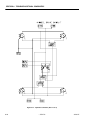
Solenoid Valve Pressure Settings - Prior to Mid 1992 with Steering Wheel. . . . . . . . . . . . . . . . . .5-23
Pressure and Flow Settings - Machines Prior to Mid 1992 with Steering Wheel . . . . . . . . . . . . . .5-24
Vickers Proportional Valve Pressure Setting - Mid 1992 to Present (Sheet 1 of 4) . . . . . . . . . . . .5-25
Vickers Proportional Valve Pressure Setting - Mid 1992 to Present (Sheet 2 of 4) . . . . . . . . . . . .5-26
Vickers Proportional Valve Pressure Setting - Mid 1992 to Present (Sheet 3 of 4) . . . . . . . . . . . .5-27
Vickers Proportional Valve Pressure Setting - Mid 1992 to Present (Sheet 4 of 4) . . . . . . . . . . . .5-28
Pressure Setting - All Hydraulic Machines (Sheet 1 of 4). . . . . . . . . . . . . . . . . . . . . . . . . . . . . . . .5-29
Pressure Setting - All Hydraulic Machines (Sheet 2 of 4). . . . . . . . . . . . . . . . . . . . . . . . . . . . . . . .5-30
Pressure Setting - All Hydraulic Machines (Sheet 3 of 4). . . . . . . . . . . . . . . . . . . . . . . . . . . . . . . .5-31
Pressure Setting - All Hydraulic Machines (Sheet 4 of 4). . . . . . . . . . . . . . . . . . . . . . . . . . . . . . . .5-32
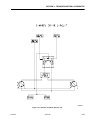
Solenoid Valve Pressure Settings - Machines Built to Present . . . . . . . . . . . . . . . . . . . . . . . . . . .5-33
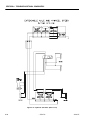
Solenoid Valve Pressure Settings - 4 Wheel Steer . . . . . . . . . . . . . . . . . . . . . . . . . . . . . . . . . . . . .5-34
Extend-A-Reach Valve Pressure and Speed Settings . . . . . . . . . . . . . . . . . . . . . . . . . . . . . . . . . .5-35
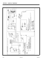
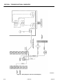
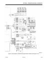
Wiring Schematic Dual Fuel . . . . . . . . . . . . . . . . . . . . . . . . . . . . . . . . . . . . . . . . . . . . . . . . . . . . . .6-21
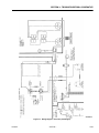
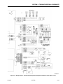
Wiring Diagram - Generator (Deutz Engines) . . . . . . . . . . . . . . . . . . . . . . . . . . . . . . . . . . . . . . . . . 6-22
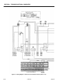
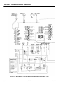
Wiring Diagram - Generator (Ford Engine). . . . . . . . . . . . . . . . . . . . . . . . . . . . . . . . . . . . . . . . . . .6-23
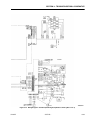
Wiring Diagram - Platform Console Standard Controls (Sheet 1 of 2). . . . . . . . . . . . . . . . . . . . . .6-24
Wiring Diagram - Platform Console Standard Controls (Sheet 2 of 2). . . . . . . . . . . . . . . . . . . . . .6-25
Wiring Diagram - Platform Console Hydraulic Controls . . . . . . . . . . . . . . . . . . . . . . . . . . . . . . . . .6-27
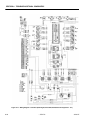
Wiring Diagram - Standard (Deutz Engine/Fixed Axle/Standard Controls) (Sheet 1 of 2). . . . . . .6-28
Wiring Diagram - Standard (Deutz Engine/Fixed Axle/Standard Controls)(Sheet 2 of 2) . . . . . . .6-29
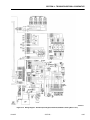
Wiring Diagram - Standard (Deutz Engine/Oscillating Axle/Standard Controls)(Sheet 1 of 2) . . .6-30
Wiring Diagram - Standard (Deutz Engine/Oscillating Axle/Standard Controls)(Sheet 2 of 2) . . .6-31
Wiring Diagram - Standard (Deutz Engine/Hydraulic Controls)(Sheet 1 of 2) . . . . . . . . . . . . . . . .6-32
Wiring Diagram - Standard (Deutz Engine/Hydraulic Controls)(Sheet 2 of 2) . . . . . . . . . . . . . . . .6-33
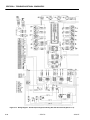
Wiring Diagram - Standard (Ford Engine/Fixed Axle/Standard Controls)(Sheet 1 of 2) . . . . . . . .6-34
Wiring Diagram - Standard (Ford Engine/Fixed Axle/Standard Controls)(Sheet 2 of 2) . . . . . . . .6-35
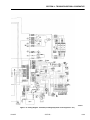
Wiring Diagram - Standard (Ford Engine/Oscillating Axle/Standard Controls)(Sheet 1 of 2) . . . .6-36
Wiring Diagram - Standard (Ford Engine/Oscillating Axle/Standard Controls)(Sheet 2 of 2) . . . .6-37
Wiring Diagram - Standard (Ford Engine/Hydraulic Controls)(Sheet 1 of 2). . . . . . . . . . . . . . . . .6-38
Wiring Diagram - Standard (Ford Engine/Hydraulic Controls)(Sheet 2 of 2). . . . . . . . . . . . . . . . .6-39
Hydraulic Schematic (Sheet 1 of 6) . . . . . . . . . . . . . . . . . . . . . . . . . . . . . . . . . . . . . . . . . . . . . . . .6-40
Hydraulic Schematic (Sheet 2 of 6) . . . . . . . . . . . . . . . . . . . . . . . . . . . . . . . . . . . . . . . . . . . . . . . .6-41
Hydraulic Schematic (Sheet 3 of 6) . . . . . . . . . . . . . . . . . . . . . . . . . . . . . . . . . . . . . . . . . . . . . . . .6-42
Hydraulic Schematic (Sheet 4 of 6) . . . . . . . . . . . . . . . . . . . . . . . . . . . . . . . . . . . . . . . . . . . . . . . .6-43
Hydraulic Schematic (Sheet 5 of 6) . . . . . . . . . . . . . . . . . . . . . . . . . . . . . . . . . . . . . . . . . . . . . . . .6-44
Hydraulic Schematic (Sheet 6 of 6) . . . . . . . . . . . . . . . . . . . . . . . . . . . . . . . . . . . . . . . . . . . . . . . .6-45
– JLG Lift –
3120271
TABLE OF CONTENTS
LIST OF TABLES
TABLE NO.
1-1.
1-2.
1-4.
1-5.
1-3
1-6
1-7.
1-8.
1-9.
2-1
2-2
2-3
4-1
5-1
5-2
6-1
6-2
6-3
6-4
6-5
6-6
3120271
TITLE
PAGE NO.
Torque Requirements . . . . . . . . . . . . . . . . . . . . . . . . . . . . . . . . . . . . . . . . . . . . . . . . . . . . . . . . . . .1-4
Lubrication Chart . . . . . . . . . . . . . . . . . . . . . . . . . . . . . . . . . . . . . . . . . . . . . . . . . . . . . . . . . . . . . . .1-6
Mobil EAL 224 H Specs. . . . . . . . . . . . . . . . . . . . . . . . . . . . . . . . . . . . . . . . . . . . . . . . . . . . . . . . . .1-10
Mobil DTE 13M Specs. . . . . . . . . . . . . . . . . . . . . . . . . . . . . . . . . . . . . . . . . . . . . . . . . . . . . . . . . . .1-10
Hydraulic Oil . . . . . . . . . . . . . . . . . . . . . . . . . . . . . . . . . . . . . . . . . . . . . . . . . . . . . . . . . . . . . . . . . .1-10
Lubrication Specifications . . . . . . . . . . . . . . . . . . . . . . . . . . . . . . . . . . . . . . . . . . . . . . . . . . . . . . . .1-10
Major Component Weights . . . . . . . . . . . . . . . . . . . . . . . . . . . . . . . . . . . . . . . . . . . . . . . . . . . . . . .1-12
Cylinder Specifications . . . . . . . . . . . . . . . . . . . . . . . . . . . . . . . . . . . . . . . . . . . . . . . . . . . . . . . . . .1-12
Critical Stability Weights . . . . . . . . . . . . . . . . . . . . . . . . . . . . . . . . . . . . . . . . . . . . . . . . . . . . . . . . .1-13
Inspection and Maintenance. . . . . . . . . . . . . . . . . . . . . . . . . . . . . . . . . . . . . . . . . . . . . . . . . . . . . .2-2
Cylinder Drift . . . . . . . . . . . . . . . . . . . . . . . . . . . . . . . . . . . . . . . . . . . . . . . . . . . . . . . . . . . . . . . . . .2-5
Preventive Maintenance and Inspection Schedule. . . . . . . . . . . . . . . . . . . . . . . . . . . . . . . . . . . . .2-8
Chain Stretch Tolerance . . . . . . . . . . . . . . . . . . . . . . . . . . . . . . . . . . . . . . . . . . . . . . . . . . . . . . . . .4-9
Cylinder Piston Nut Torque Specifications . . . . . . . . . . . . . . . . . . . . . . . . . . . . . . . . . . . . . . . . . . .5-13
Holding Valve Torque Specification . . . . . . . . . . . . . . . . . . . . . . . . . . . . . . . . . . . . . . . . . . . . . . . .5-14
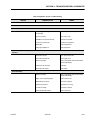
Platform Assembly - Troubleshooting. . . . . . . . . . . . . . . . . . . . . . . . . . . . . . . . . . . . . . . . . . . . . . .6-2
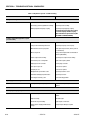
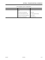
Boom Assembly - Troubleshooting . . . . . . . . . . . . . . . . . . . . . . . . . . . . . . . . . . . . . . . . . . . . . . . .6-3
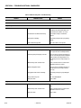
Turntable Assembly - Troubleshooting. . . . . . . . . . . . . . . . . . . . . . . . . . . . . . . . . . . . . . . . . . . . . .6-8
Chassis Assembly - Troubleshooting . . . . . . . . . . . . . . . . . . . . . . . . . . . . . . . . . . . . . . . . . . . . . . .6-9
Hydraulic System - Troubleshooting. . . . . . . . . . . . . . . . . . . . . . . . . . . . . . . . . . . . . . . . . . . . . . . .6-15
Electrical System - Troubleshooting . . . . . . . . . . . . . . . . . . . . . . . . . . . . . . . . . . . . . . . . . . . . . . . .6-18
– JLG Lift –
vii
TABLE OF CONTENTS (Continued)
This page left blank intentionally.
viii
– JLG Lift –
3120271
SECTION 1 - SPECIFICATIONS
SECTION 1. SPECIFICATIONS
1.1
Engine - Deutz F4L912
CAPACITIES
Oil Capacity - 9.5 quarts (8.99 L) w/Filter, 8.5 quarts
(8.04 L) w/o Filter.
Fuel Tank - 26 U.S. Gallons (98 L).
Hydraulic Oil Tank - 55 U.S. Gallons (208 L).
Low RPM 1800.
Hydraulic System (Including Tank) - Approx. 66
U.S. Gallons (250 L).
Mid RPM N/A
Torque Hub, Drive - 44 oz. (1.3 L).
High RPM 2400.
Torque Hub, Swing - 17 oz. (0.5 L).
Alternator - 60 Amp, belt drive.
NOTE: Torque Hubs should be one-half full of lubricant.
(EPGL-90)
Battery - 85 Amp hour, 550 CCA, 12 VDC.
Horsepower - 70 @ 2400 RPM, no load.
Engine - Wisconsin V465D
Engine Crankcase (Ford LSG423) w/Filter - 5 quarts
(4.73 L).
Oil Capacity - 7 quarts (6.62 L) w/Filter, 6 quarts (5.68 L)
w/o Filter.
Engine Crankcase (Deutz F3L912) w/Filter - 9.5 quarts
(9 L).
Low RPM 1800, no load.
Engine Crankcase (Wisconsin V465D) w/Filter - 7 quarts
(6.6 L).
High RPM 2400, no load.
Engine Crankcase (Cummins 4B 3.9C) - 11.5 quarts
(10.9 L).
Battery - 1000 cold cranking Amps, 210 minutes
reserve capacity, 12 VDC.
Tolerance on all engine rpm settings is plus or minus 10%.
Horsepower - 60 @ 2400 RPM, no load.
Alternator - 37 Amp, belt drive.
Engine - Cummins 4B 3.9C
1.2
COMPONENT DATA
Oil Capacity - 11.5 quarts (10.9 L).
Engine - Ford LSG423
Cooling System - 7.4 quarts (7.0 L)
Oil Capacity - 5 quarts (4.7 L) w/Filter, 4 quarts (3.8 L)
w/o Filter.
Battery - 1000 cold cranking Amps, 210 minutes
reserve capacity, 12 VDC.
Cooling System - 16 quarts (15 L).
Horsepower - 76 @ 2500 RPM, no load.
Low RPM - 1000, no load
Mid RPM - 1800, no load.
High RPM - 3000, no load.
Alternator - 40 Amp, belt drive.
Battery - 1000 cold cranking Amps, 210 minutes reserve
capacity, 12 VDC.
Horsepower - 63 @ 2800 RPM, no load.
3120271
– JLG Lift –
1-1
SECTION 1 - SPECIFICATIONS
Engine - Ford LRG-423
2WD/2WS with fixed or oscillating front axle built
May 1988 to present - 24:1.
Oil Capacity - 5 quarts (4.7 L).
Low RPM 1000
2WD/4WS with oscillating front axle built May 1988
to present - 24:1.
Mid RPM 1800
4WD built May 1988 to present - 24:1.
High RPM 3000
2WD/4WS with fixed front axle/Vickers proportional
valves - 73:1.
Horsepower - 66.
4WD with Vickers Proportional valves - 30.04:1.
Engine - Ford LRG-425
Oil Capacity - 4.5 quarts (4.25 L).
Steer System
Low RPM 1000
Toe-in, adjust for 1/4 in. (6.35 mm) overall.
Mid RPM 1800
Swing System
High RPM 3000
Horsepower - 75
Swing Motor - Displacement - 4.5 cu. in/Rev.
Drive System
Swing Hub - Ratio - 69.50:1.
Pneumatic Tires - 15 x 19.5 NHS, 12 ply rating,
65 PSI. (4.5 Bar).
Swing Brake - Automatic spring applied, hydraulically released disc brakes.
Foam-Filled Tires - 15 x 22.5 or 385/65R22.5
Hydraulic Pump
Air Pressure:
Firestone Tires - 95 PSI (6.5 Bar)
Goodyear Tires - 65 PSI (4.5 Bar)
Denman Tires - 70 PSI (4.8 Bar).
Deutz and Wisconsin engines with Single Speed Drive
Motors (with Racine Valves).
First Section to Proportional Valve-Drive, Lift, Swing 24 GPM (91 LPM).
Drive Motor Displacement Machines Built Prior
to Jan. 1992
Second Section to High Drive - 24 GPM (91 LPM).
Cessna - 5.04 in.3/rev. (4WD Same)
Third Section to Bang-Bang Valve Level, Telescope,
Steer, Rotate - 9.5 GPM (36 LPM).
Vickers - 2.5/.98 in.3/rev.
(4WD Same)
2 Speed Cessna - 2.48/1.103/rev.
Clockwise Rotation.
Gear Reducer - Vickers Drive Motors only - 3.6:1.
Drive Motor Displacement Machines Built from
Jan. 1992 to Present
Wisconsin Engines with 2 Speed Drive Motors and Deutz
Engines with Single Speed Drive Motors (with Racine
Valves).
First Section to Proportional Valve-Drive, Lift, Swing 19 GPM (72 LPM).
Rexroth - 2.8 in.3/rev.
(4WD Same)
Drive Hub Ratios
Second Section to High Drive - 19 GPM (72 LPM).
2WD with Racine proportional valves built prior to
February 1988 - 42.5:1.
Third Section to Bang-Bang Valve Level, Telescope,
Steer, Rotate - 9.5 GPM (36 LPM).
2WD with Racine proportional valves built February 1988
to present - 43:1.
Clockwise Rotation.
2WD with Racine or Vickers proportional valves built prior
to October 1989 - 30.04:1.
1-2
– JLG Lift –
3120271
SECTION 1 - SPECIFICATIONS
Deutz Engines with 2 Speed Drive Motors (with Racine
Valves).
1.3
PERFORMANCE DATA
First Section to Proportional Valve-Drive, Lift, Swing 19 GPM (72 LPM).
Travel Speed
Second Section to High Drive - 14.5 GPM (55 LPM).
Gradeability
Third Section to Bang-Bang Valve Level, Telescope,
Steer, Rotate - 9.5 GPM (36 LPM).
25%.
3.5 MPH (5.6 KM/HR).
Turning Radius (Outside)
Clockwise Rotation.
24 ft. (7.3 m) with axles extended.
Machines Built Prior to Mid 1987 (with Vickers Valves).
First Section to Proportional Valve-Drive, Lift, Swing 14.5 GPM (55 LPM).
Boom Speed (Telescope)
Extend 71-133 Seconds
Retract 44-72 Seconds.
Second Section to High Drive - 9.5 GPM (36 LPM).
Boom Speed (Lift)
Third Section to Bang-Bang Valve Level, Telescope,
Steer, Rotate - 9.5 GPM (36 LPM).
Up - 65-100 Seconds
Down - 55-100 Seconds.
Clockwise Rotation.
Swing Speed 360°
Machines Built Mid 1987 to Present (with Vickers Valves).
First Section to Proportional Valve-Drive, Lift, Swing 15 GPM (57 LPM).
Boom Elevation
-16° to +75°
Second Section to High Drive - 9 GPM (34 LPM).
Third Section to Bang-Bang Valve Level, Telescope,
Steer, Rotate - 9 GPM (34 LPM).
Machine Weight
80HX - approx. 31,800 LBS. (14,424 KG.)
80HX+6 - approx. 36,900 LBS. (16,738 KG.)
Clockwise Rotation.
Machine Stowed Height
Auxiliary Power Pump
Two section, 3.75 GPM (14.19 lpm) each section, 12 VDC
motor, clockwise rotation.
Hydraulic Filter - Tank
Swing Speed 360° - 110-200 Seconds.
9.5 ft. (2.9 M)
Machine Stowed Length
80HX - 33.5 ft. (10.2 M)
Return - Bypass Type.
80HX+6 - 36.7 ft. (11.2 M)
10 Microns Nominal.
Machine Width
Hydraulic Filter - Inline (Racine Valve Only)
Return - Non-Bypass Type.
With axles retracted - 8 ft. (2.4 m)
With axles extended - 10 ft. (3 m)
10 Microns Nominal.
Maximum Tire Load
80HX - 15500 lbs. (7037 kg) @103 psi (7.1 Bar)
80HX + 6 - 18295 (8299 kg) @107 psi (7.4 Bar)
Wheelbase
10 ft. (3 m)
3120271
– JLG Lift –
1-3
SECTION 1 - SPECIFICATIONS
1.4
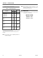
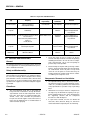
NOTE: When maintenance becomes necessary or a fastener has loosened, refer to the Torque Chart to
determine proper torque value.
TORQUE REQUIREMENTS
Table 1-1. Torque Requirements
Torque
Description
Interval
Hours
Ft. Lbs.
Nm
170
220
460
600
235
304
636
830
Turntable (April, 1986 to Present)
Wet
Dry
170
220
235
304
50/600*
Wheel Lugs
Wet
Dry
220
300
304
415
100
Drive Hub
Wet
Dry
110
150
149
207
200/
500**
Swing Hub
Wet
Dry
80
110
110
149
200/
500**
Turntable (prior to April, 1986)
5/8" Bolts - Wet
5/8" Bolts - Dry
7/8" Bolts - Wet
7/8" Bolts - Dry
1.5
LUBRICATION
NOTE: The lubrication intervals in the following paragraphs
are equivalent to the following:
50/600*
150 hours = 3 months
300 hours = 6 months
600 hours = 1 year
1200 hours = 2 years
* Check swing bearing bolts for security after first 50 hours of
operation and every 600 hours thereafter.
**Retorque after first 200 hours of operation and every 500 hours
thereafter.
NOTE: See Procedure Section for tightening sequence of
turntable bearing bolts.
1-4
– JLG Lift –
3120271
SECTION 1 - SPECIFICATIONS
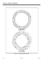
Figure 1-1. Lubrication Diagram
3120271
– JLG Lift –
1-5
SECTION 1 - SPECIFICATIONS
Table 1-2. Lubrication Chart
Interval
Components
Number/Type
Lube Points
Capacity
Level/Fill Plug
2.75 pt. (1/2 full)
EPGL
(SAE90
)
Lube
3
Months
150 hrs
Hours
6
Months
300 hrs
Comments
1 Year
600 hrs
2 Years
1200 hrs
1
Wheel Drive Hubs
2
Slave Cylinder (Rod)
1 Grease Fitting
A/R
MPG
X
3
Slave Cylinder (Barrel)
1 Grease Fitting
A/R
MPG
X
4
Platform Pivot
1 Grease Fitting
A/R
MPG
X
5
Rotating Column
(Optional)
2 Grease Fittings
A/R
MPG
6
Rotary Worm Gear
(Optional)
N/A
A/R
MPG
X
7
Platform Hinges
2 Grease Fittings
A/R
MPG
X
8
Platform Latch
N/A
A/R
EO
X
9
Boom Chain Extension
Sheave
1 Grease Fitting
A/R
MPG
X
Align access holes in mid and fly boom.
1
0
Swing Bearing
2 Grease Fittings
A/R
MPG
X
Remote Access
1
1
Lift Cylinder (Barrel End)
1 Grease Fitting
A/R
MPG
X
Remote Access
1
2
Master Cylinder (Barrel
End)
1 Grease Fitting
A/R
MPG
X
Remote Access
1
3
Master Cylinder (Rod
End)
1 Grease Fitting
A/R
MPG
X
1-6
X
Check level every 150 hours; change @
1200 hours
Gain access through boom fly section.
X
– JLG Lift –
Brush on.
3120271
SECTION 1 - SPECIFICATIONS
Table 1-2. Lubrication Chart
Interval
Components
Number/Type
Lube Points
Capacity
Lube
3
Months
150 hrs
Hours
6
Months
300 hrs
Comments
1 Year
600 hrs
2 Years
1200 hrs
1
4
Boom Chain Retract
Sheave
1 Grease Fitting
A/R
MPG
X
1
5
Boom Pivot Bushings
2 Grease Fittings
A/R
MoS2
X
1
6
Engine Crankcase
Fill Cap
Refer to Engine Manual
EO
Check daily. Change in accordance with
engine manual.
1
7
Engine Oil Filter
N/A
N/A
N/A
Change in accordance with engine manual.
1
8
Engine Coolant
Radiator Cap
Refer to Engine Manual
1
9
Hydraulic Oil
Fill Cap
56 gallons
HO
2
0
Hydraulic Oil Return
Filters
N/A
N/A
N/A
2
1
Hydraulic Reservoir
Suction Filter
N/A
N/A
N/A
2
2
Tie Rod Ends
2 Grease Fittings
A/R
MPG
X
2
3
King Pins
2 Grease Fittings
A/R
MPG
X
2
4
Steer Cylinder (Rod
End)
1 Grease Fitting
A/R
MPG
X
2
5
Steer Cylinder (Barrel
End)
1 Grease Fitting
A/R
MPG
X
2
6
Wheel Bearings
N/A
A/R
2
7
Swing Drive Hub
Fill Plug
2
8
Swing Bearing and
Pinion Gear Teeth
2
9
Refer to engine manual for coolant specifications. Check daily with engine cold.
X
Check daily. Change every 1200 hours.
Check filter gauges for element construction daily. Replace as necessary.
X
Replace filter element every 600 hours;
clean mesh as necessary.
MPG
X
Repack
17 oz. (1/2 Full)
EPGL
(SAE90
)
X
Check oil level weekly; change every 600
hours
N/A
A/R
MPG
X
Apply by brush onto bearing and gear teeth
Axle Beam (Extendable
Axles)
N/A
A/R
MPG
3
0
Axle Lock Pin
(Extendable Axles)
N/A
A/R
MPG
X
3
1
Oscillating Axle Pivot
1 Grease Fitting
A/R
MPG
X
3
2
Oscillation Cylinder
2 Grease Fittings
A/R
MPG
X
3
3
Extend-A-Reach Pivot (If
Equipped)
2 Grease Fittings
A/R
MPG
X
3120271
X
– JLG Lift –
Apply by brush
Apply by brush
1-7
SECTION 1 - SPECIFICATIONS
Table 1-2. Lubrication Chart
Interval
Components
Number/Type
Lube Points
Capacity
Lube
3
Months
150 hrs
3
4
Extend-A-Reach Lift
Cylinder (Barrel End)
1 Grease Fitting
A/R
MPG
X
3
5
Extend-A-Reach Lift
Cylinder (Rod End)
1 Grease Fitting
A/R
MPG
X
3
6
Extend-A-Reach - Boom
End (If Equipped)
2 Grease Fittings
A/R
MPG
X
3
7
Extend-A-Reach Platform End (if
Equipped)
1 Grease Fitting
A/R
MPG
X
3
8
Extend-A-Reach - Slave
Cylinder Rod End (If
Equipped)
1 Grease Fittings
A/R
MPG
X
3
9
Extend-A-Reach Link Slave Cylinder Pivot
Point (If Equipped)
1 Grease Fitting
A/R
MPG
X
4
0
Extend-A-Reach Link Slave Cylinder Pivot
Point (If Equipped)
1 Grease Fitting
A/R
MPG
X
6
Months
300 hrs
Hours
Comments
1 Year
600 hrs
2 Years
1200 hrs
NOTES:
KEY TO LUBRICANTS
Lubrication intervals are based on machine operation under normal conditions. For machines used in multi shift operations and/or exposed to hostile
environments or conditions, lubrication frequencies must be increased accordingly.
1-8
– JLG Lift –
EO
EPGL
HO
MPG
Engine Oil
Extreme Pressure Gear Lube
Hydraulic Fluid (Mobil #424 or equivalent)
Multi-Purpose Grease
3120271
SECTION 1 - SPECIFICATIONS
Ford Engines
Wisconsin V465D Engine
Single Viscosity Oils (SF, SF-SE, SF-CC, SF-CD).
When Outside Temp
is Consistently
-10° F - +60° F.
+10° F - + 90° F.
Above +32° F.
Above + 50° F.
Single Viscosity Oils (MS, SD, SE).
Use SAE
Viscosity Number
*10W
20W-20
30
40
When Outside Temp
is Consistently
+15° F - 0° F.
+40° F - + 15° F.
+120° F - + 40° F.
Multi-Viscosity Oils (MS, SD, SE).
Multi-Viscosity Oils (SF, SF-SE, SF-CC, SF-CD).
When Outside Temp
is Consistently
Below +10° F.
Below +60° F.
-10° F - +90° F.
Above -10° F.
Use SAE
Viscosity Number
*5W-20
5W-30
10W-30
10W-40 or
Above +20° F.
10W-50
20W-40 or
When Outside Temp
is Consistently
Below Zero.
Use SAE
Viscosity Number
*5W-20
NOTE: Crankcase oil should meet one of the following API
classification grades: SE/CC, SE/CD, SF/CC, SF/
CD.
Cummins 4B 3.9C
20W-50
Multiple Viscosity Oils (CE/SG).
* Not recommended for severe service - including high RPM operation.
When Outside Temp
is Consistently
+70° F - 40° F.
+70° F - -10° F.
+120° F - + 10° F.
Deutz F4L912 Engine
Single Viscosity Oils (CD-SE, CD-SF).
When Outside Temp
is Consistently
-20° F - +25° F.
+15° F - + 50° F.
+40° F - + 85° F.
Above 75° F.
Use SAE
Viscosity Number
*10W
20-20W
30
Use SAE
Viscosity Number
5W-30
10W-30
15W-40
Use SAE
Viscosity Number
*10W
20W-20
30
40
Multi-Viscosity Oils (CD-SE, CD-SF).
When Outside Temp
is Consistently
-40° F - +75° F.
Use SAE
Viscosity Number
*5W-20
-5° F - +70° F.
-5° F - +85° F.
+15° F - +75° F.
Above +15° F.
(Synthetic)
10W-30
10W-40
15W-30
15W-40
* This viscosity can be used at colder temperatures only
with engine oil preheating.
.
3120271
– JLG Lift –
1-9
SECTION 1 - SPECIFICATIONS
Table 1-5. Mobil DTE 13M Specs
Table 1-3.Hydraulic Oil
Hydraulic System Operating
Temperature Range
SAE Viscosity
Grade
0° to +23° F(-18° to -5° C)
10W
0° to +210° F(-18° to +100° C)
10W-20, 10W-30
+50° to +210° F(+10° to +99° C)
20W-20
Type
Petroleum Base
ISO Viscosity Grade
32
Specific Gravity
.877
Pour Point, Max
-40°F (-40°C)
Flash Point, Min.
330°F (166°C)
NOTE: Hydraulic oils must have anti-wear qualities at least
to API Service Classification GL-3, and sufficient
chemical stability for mobile hydraulic system service. JLG Industries recommends Mobilfluid 424
hydraulic oil, which has an SAE viscosity index of
152.
Viscosity
at 104° F (40° C)
33 cSt
at 212° F (100° C)
6.5 cSt
Viscosity Index
140
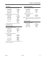
Lubrication Specifications
NOTE: When temperatures remain consistently below 20
degrees F (-7 degrees C.), JLG Industries recommends the use of Mobil DTE11.
NOTE: Aside from JLG recommendations, it is not advisable
to mix oils of different brands or types, as they may
not contain the same required additives or be of
comparable viscosities. If use of hydraulic oil other
than Mobilfluid 424 is desired, contact JLG Industries for proper recommendations.
Table 1-6.Lubrication Specifications
KEY
MPG
Multipurpose Grease having a minimum dripping point of
350 degrees F. Excellent water resistance and adhesive qualities; and being of extreme pressure type (Timken OK 40
pounds minimum).
EPGL
Extreme Pressure Gear Lube (oil) meeting API Service Classification GL-5 or Mil-Spec Mil-L-2105.
HO
Hydraulic Oil. API Service Classification GL-3, SAE 10W-20,
Viscosity Index 152.
EO
Engine (crankcase) Oil. Gas - API SF/SG class, MIL-L-2104.
Diesel - API CC/CD class, MIL-L-2104B/MIL-L-2104C.
Table 1-4. Mobil EAL 224 H Specs
Type
Biodegradable Vegetable Oil
ISO Viscosity Grade
32/46
Specific Gravity
.922
Pour Point, Max
-25°F (-32°C)
Flash Point, Min.
428°F (220°C)
Weight
7.64 lb. per gal.
(0.9 kg per liter)
Viscosity
at 104° F (40° C)
37 cSt
at 212° F (100° C)
8.4 cSt
Viscosity Index
213
Operating Temp
0-180° F (-17 - -162°C)
Note: Must be stored above 32° F (14° C)
SPECIFICATIONS
Refer to Lubrication Chart for specific lubrication procedures.
1.6
PRESSURE SETTINGS
NOTE: All pressure are given in pounds per square inch
(psi), with the metric equivalent, Bar, in parentheses.
Prior to Mid 1987
Main Relief - 2900 psi (200 Bar).
Drive - 2900 psi (200 Bar).
Lift Up - 2900 psi (200 Bar).
Lift Down - 1100 psi (76 Bar).
Swing - 1200 psi (83 Bar).
Main Relief (Solenoid Valve) - 2500 psi (172 Bar).
Telescope In - 2500 psi (172 Bar).
Telescope Out - 1500 psi (103 Bar).
1-10
– JLG Lift –
3120271
SECTION 1 - SPECIFICATIONS
80HX w/Hydraulic Controls
Rotate - 2500 psi (172 Bar)
Level - 1500 psi, 2500 psi Split Valve (103 Bar,
172 Bar Split Valve).
Proportional Relief - Standard 3200 psi (220 Bar);
Prop. Tele 3850 psi (265 Bar).
Steer - 1500 psi (103 Bar) without steering wheel
Sequence (Load Sense) - 400 to 600 psi (28 to 41 Bar).
Steer - 2500 psi (with steering wheel)
Pressure Reducing (Pilot Press) - 600 psi (41 Bar).
80 HX
Hyd. Controls Back Pressure - Relief 125 psi (8.6 Bar);
Press. Red. 80 to 120 psi (5.5 to 8.2 Bar)
Proportional Relief - Standard 3200 psi (220 Bar);
Prop. Tele 3850 psi (265 Bar).
Drive - 3100 psi. (214 Bar); Prop. Tele. 3750 psi (259 Bar).
Lift Up - 3000 psi (207 Bar).
Sequence (Load Sense) - 450 psi (31 Bar).
Lift Down - 1500 psi (103 Bar)
Pressure Reducing (Pilot Press) - 550 psi (38 Bar).
Drive - 3100 psi. (214 Bar); Prop. Tele. 3750 psi (259 Bar).
Swing - 1500 psi (103 Bar).
Telescope In - 3000 psi (207 Bar); Prop. Tele 3750 psi (259
Bar).
Lift Up - 3000 psi (207 Bar).
Lift Down - 1500 psi (103 Bar)
Tele Out - 1500 psi (103 Bar).
Swing - 1500 psi (103 Bar).
Solenoid Main Relief - 3100 psi (214 Bar)
Telescope In - 3000 psi (207 Bar); Prop. Tele 3750 psi
(259 Bar).
2 Wheel Steer - 2000 psi (138 Bar); w/axle lift cyl. 2200 psi
(152 Bar)
Tele Out - 1500 psi (103 Bar).
Solenoid Main Relief - 3100 psi (214 Bar).
2 Wheel Steer w/4WD - 2000 psi (138 Bar); w/axle lift cyl.
2200 psi (152 Bar).
2 Wheel Steer - 2000 psi (138 Bar); w/axle lift cyl. 2200 psi
(152 Bar)
4 Wheel Steer - 2000 psi (138 Bar); w/axle lift cyl. 2200 psi
(152 Bar).
2 Wheel Steer w/4WD - 2000 psi (138 Bar); w/axle lift cyl.
2200 psi (152 Bar).
Extend-A-Reach Up - 2500 psi (172 Bar).
4 Wheel Steer - 2000 psi (138 Bar) w/axle lift cyl. 2200 psi
(152 Bar).
Extend-A-Reach Up - 2500 psi (172 Bar).
Extend-A-Reach Down - 1100 psi (76 Bar).
Extend-A-Reach Down - 1100 psi (76 Bar).
80HX w/Oscillating Axle
Proportional Relief - Standard 3200 psi (220 Bar);
Prop. Tele 3850 psi (265 Bar).
Sequence (Load Sense) - 450 psi (31 Bar).
Pressure Reducing (Pilot Press) - 550 psi (38 Bar).
Drive - 3100 psi. (214 Bar); Prop. Tele. 3750 psi (259 Bar).
Lift Up - 3000 psi (207 Bar).
3120271
– JLG Lift –
1-11
SECTION 1 - SPECIFICATIONS
Lift Down - 1500 psi (103 Bar)
1.8
Swing - 1500 psi (103 Bar).
CYLINDER SPECIFICATIONS
Table 1-8. Cylinder Specifications
Telescope In - 3000 psi (207 Bar) Prop. Tele 3750 psi
(259 Bar).
BORE
DESCRIPTION
Tele Out - 1500 psi (103 Bar).
STROKE ROD DIA.
Master Level
2.50
15.25
1.25
Slave Level
2.50
15.21
1.25
2 Wheel Steer w/4WD - 1500 psi (103 Bar).
Lift
8.00
30.75
3.50
4 Wheel Steer; Axle Lift Cyl. - 2200 psi (152 Bar).
Lockout
4.00
4.88
1.25
Extend-A-Reach Up - 2500 psi (172 Bar)
(Oscillating Axle)
Extend-A-Reach Down - 1100 psi (76 Bar)
Lockout
4.00
4.25
1.25
Telescope
3.50
257.9
2.50
Steer (2WD)
3.00
8.06
1.25
Steer (4WD)
3.00
9.81
1.50
Solenoid Main Relief - 3100 psi (214 Bar)
2 Wheel Steer - 1500 psi (103 Bar)
NOTE: Refer to Section 2 for pressure setting procedures.
1.7
MAJOR COMPONENTS WEIGHTS
Table 1-7. Major Component Weights
(4WD)
Extend-A-Reach
Component
Lbs.
KG.
Lift
3.00
12.687
2.00
Platform w/o Control Box
236
107
Slave
3.50
7.25
1.75
Boom (includes Lift Cylinder, Rotator, and Support)
4816
2184
Turntable Complete (includes Engine)
14972
6790
Frame Complete (includes Tires and Wheels)
9290
4213
Complete Machine - 2WD No Options
28605
1297
3
1.9
BOOM TAPE
American Standard
Red - 39 in. (99 cm).
Complete Machine - 4WD No Options
29106
1320
0
Complete Machine (80HX+6) 2WD No Options
31856
1444
7
Yellow - 34 in. (86.4 cm).
Blue - 193.9 in. (492.5 cm).
Canadian Standard
Red - 53 in. (134.6 cm).
Yellow - 42 in. (106.7 cm).
Blue - 171.8 in. (436.4 cm).
1-12
– JLG Lift –
3120271
SECTION 1 - SPECIFICATIONS
1.10 CRITICAL STABILITY WEIGHTS
1.11 SERIAL NUMBER LOCATION
Table 1-9. Critical Stability Weights
Component
Engines
Tire & Wheels
Lb.s
KG.
Deutz F4L912
837
380
Ford LRG 423
410
186
Cummins 4B3.9
680
309
15x19.5 Tire
130
59
Wheel
72
33
Foam Fill
320
145
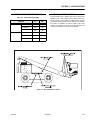
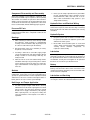
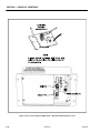
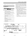
A serial number plate is affixed to the left rear front of the
turntable. If the serial number plate is damaged or missing, the machine serial number is stamped on the left side
of the frame between front and rear wheels, below turntable bearing. In addition, the last five digits of the serial
number are stamped on top of the fly, mid and base end
of the boom and on the left side of the turntable.
Figure 1-2. Serial Number Locations
3120271
– JLG Lift –
1-13
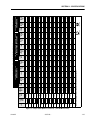
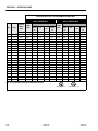
1-14
– JLG Lift –
18
24
16
24
14
20
13
20
12
18
11
18
10
16
9
14
8
12
7
12
7
12
6
12
6
12
40
48
32
40
32
36
24
32
20
28
1.5000
1.3750
1.2500
1.1250
1.0000
0.8750
0.7500
0.6250
0.5625
0.5000
0.4375
0.3750
0.3125
IN
0.2500
0.1900
0.1640
0.1380
0.1120
IN
BOLT
DIA.
0.0524
0.0580
0.0775
0.0878
0.1063
0.1187
0.1419
0.1599
0.1820
0.2030
0.2260
0.2560
0.3340
0.3730
0.4620
0.5090
0.6060
0.6630
0.7630
0.8560
0.9690
1.0730
1.1550
1.3150
1.4050
1.5800
SQ. IN.
0.00604
0.00661
0.00909
0.01015
0.01400
0.01474
0.01750
0.02000
0.0318
0.0364
SQ. IN.
3340
3700
4940
5600
6800
7550
9050
10700
11600
12950
14400
16300
21300
23800
29400
32400
38600
42200
42300
47500
53800
59600
64100
73000
78000
87700
LB.
380
420
580
610
900
940
1120
1285
2020
2320
LB.
17
19
30
35
50
55
75
90
110
120
150
170
260
300
430
470
640
700
800
880
1120
1240
1460
1680
1940
2200
FT-LB
8
9
16
18
30
31
43
49
96
120
IN-LB
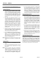
263
TENSILE
CLAMP DRY OR
STRESS
LOAD LOCTITE
AREA
13
14
23
25
35
40
55
65
80
90
110
130
200
220
320
350
480
530
600
660
840
920
1100
1260
1460
1640
FT-LB
6
7
12
13
22
23
32
36
75
86
IN-LB
LUB
16
17
28
32
45
50
68
80
98
109
135
153
240
268
386
425
579
633
714
802
1009
1118
1322
1506
1755
1974
FT-LB
—
—
—
—
—
—
—
—
—
—
IN-LB
LOCTITE
262
TORQUE
Note: These torque values do not apply to cadmium plated fasteners.
1-1/2
1-3/8
1-1/4
1-1/8
1
7/8
3/4
5/8
9/16
1/2
7/16
3/8
5/16
1/4
10
8
6
4
SIZE
THDS.
PER
INCH
19
21
35
40
55
60
85
100
120
135
165
190
285
330
475
520
675
735
840
925
1175
1300
1525
1750
2025
2300
FT-LB
—
—
—
—
—
—
—
—
105
135
IN-LB
LOCTITE
242 OR
271
4720
5220
7000
7900
9550
10700
12750
14400
16400
18250
20350
23000
30100
33600
41600
45800
51500
59700
68700
77000
87200
96600
104000
118100
126500
142200
LB.
540
600
820
920
1260
1320
1580
1800
2860
3280
LB.
CLAMP
LOAD
25
25
45
50
70
80
110
120
150
170
220
240
380
420
600
660
900
1000
1280
1440
1820
2000
2380
2720
3160
3560
FT-LB
12
13
23
25
41
43
60
68
144
168
IN-LB.
DRY OR
LOCTITE
263
18
20
35
35
55
60
80
90
110
130
170
180
280
320
460
500
680
740
960
1080
1360
1500
1780
2040
2360
2660
FT-LB
9
10
17
19
31
32
45
51
108
120
IN-LB
LUB
22
25
40
45
63
70
96
108
139
154
180
204
301
336
485
534
687
796
1030
1155
1453
1610
1907
2165
2530
2844
FT-LB
—
—
—
—
—
—
—
—
—
—
IN-LB
LOCTITE
262
TORQUE
UNPLATED CAP SCREWS
5240
5800
7750
8780
10630
11870
14190
15990
18200
20300
22600
25600
33400
37300
46200
50900
60600
66300
76300
85600
96900
107300
115500
131500
140500
158000
LB.
—
—
—
—
—
—
—
—
3180
3640
LB.
SAE GRADE 8
25
27
45
50
70
75
110
115
155
165
210
220
365
400
585
635
865
915
1240
1380
1750
1880
2320
2440
3040
3270
FT-LB
—
—
—
—
—
—
—
—
160
168
IN-LB
PATCH
28
30
50
55
77
82
120
127
170
182
231
242
400
440
645
700
950
1000
1365
1520
1925
2070
2550
2685
3345
3600
FT-LB
—
—
—
—
—
—
—
—
168
178
IN-LB
PATCH
TORQUE
CLAMP WITHOUT WITH
LOAD LOC-WEL LOC-WEL
UNBRAKO 1960 SERIES
SOCKET HEAD
SAE GRADE 5
30
30
50
55
80
90
120
130
165
190
240
265
420
465
660
725
990
1100
1400
1575
2000
2200
2625
3000
3475
3925
FT-LB
—
—
—
—
—
—
—
—
160
185
IN-LB
LOCTITE
242 OR
271
SAE GRADE 8 BOLTS & GRADE 8 NUTS
& SOCKET HEAD CAP SCREWS
VALUES FOR ZINC PLATED / YELLOW CHROMATE FASTENERS ONLY
SAE GRADE 5 BOLTS &
GRADE 2 NUTS
SECTION 1 - SPECIFICATIONS
Figure 1-3. Torque Chart - (In/Lb - Ft/Lb). (For ASTM Fasteners)
3120271
3120271
– JLG Lift –
18
24
16
24
14
20
13
20
12
18
11
18
10
16
9
14
8
12
7
12
7
12
6
12
6
12
40
48
32
40
32
36
24
32
20
28
SQ. IN.
1.5000
1.3750
1.2500
1.1250
1.0000
0.8750
0.7500
0.6250
0.5625
0.5000
0.4375
0.3750
0.3125
IN
0.2500
0.1900
0.1640
0.1380
0.0524
0.0580
0.0775
0.0878
0.1063
0.1187
0.1419
0.1599
0.1820
0.2030
0.2260
0.2560
0.3340
0.3730
0.4620
0.5090
0.6060
0.6630
0.7630
0.8560
0.9690
1.0730
1.1550
1.3150
1.4050
1.5800
SQ. IN.
0.00604
0.00661
0.00909
0.01015
0.01400
0.01474
0.01750
0.02000
0.0318
0.0364
IN
0.1120
TENSILE
STRESS
AREA
BOLT
DIA.
3340
3700
4940
5600
6800
7550
9050
10700
11600
12950
14400
16300
21300
23800
29400
32400
38600
42200
42300
47500
53800
59600
64100
73000
78000
87700
LB.
380
420
580
610
900
940
1120
1285
2020
2320
LB.
CLAMP
LOAD
23
26
41
47
68
75
102
122
149
163
203
230
353
407
583
637
868
949
1085
1193
1518
1681
1979
2278
2630
2983
N, m
.8
1.0
1.8
2.0
3.4
3.4
5
6
11
14
DRY OR
LOCTITE
263
N, m
18
19
31
34
47
54
75
88
108
122
149
176
271
298
434
475
651
719
813
895
1139
1247
1491
1708
1979
2224
N, m
.8
.8
1.4
1.6
2.4
2.6
3.6
4
8
10
N, m
LUB
22
23
38
43
61
68
92
108
133
148
183
207
325
363
523
576
785
858
968
1087
1368
1516
1792
2042
2379
2676
N, m
—
—
—
—
—
—
—
—
—
—
N, m
LOCTITE
262
TORQUE
Note: These torque values do not apply to cadmium plated fasteners.
1-1/2
1-3/8
1-1/4
1-1/8
1
7/8
3/4
5/8
9/16
1/2
7/16
3/8
5/16
1/4
10
8
6
4
SIZE
THDS.
PER
INCH
26
28
47
54
75
81
115
136
163
183
224
258
386
447
644
705
915
997
1139
1254
1593
1763
2068
2373
2745
3118
N, m
—
—
—
—
—
—
—
—
12
15
LOCTITE
242 OR
271
N, m
4720
5220
7000
7900
9550
10700
12750
14400
16400
18250
20350
23000
30100
33600
41600
45800
51500
59700
68700
77000
87200
96600
104000
118100
126500
142200
LB.
540
600
820
920
1260
1320
1580
1800
2860
3280
LB.
CLAMP
LOAD
34
34
61
68
95
108
149
163
203
230
298
325
515
569
813
895
1220
1356
1735
1952
2468
2712
3227
3688
4284
4827
N, m
1.4
1.5
2.6
2.8
4.6
5
7
8
16
19
DRY OR
LOCTITE
263
N, m
24
27
47
47
75
81
108
122
149
176
230
244
380
434
624
678
922
1003
1302
1464
1844
2034
2413
2766
3200
3606
N, m
1.0
1.0
2.0
2.2
3.4
3.6
5
6
12
14
N, m
LUB
30
34
54
61
85
95
130
146
188
209
244
277
408
456
658
724
931
1079
1396
1566
1970
2183
2586
2935
3430
3856
N, m
—
—
—
—
—
—
—
—
—
—
N, m
LOCTITE
262
TORQUE
UNPLATED CAP SCREWS
5240
5800
7750
8780
10630
11870
14190
15990
18200
20300
22600
25600
33400
37300
46200
50900
60600
66300
76300
85600
96900
107300
115500
131500
140500
158000
LB.
—
—
—
—
—
—
—
—
3180
3640
LB.
CLAMP
LOAD
SAE GRADE 8
34
37
61
68
95
102
149
156
210
224
285
298
495
542
793
861
1173
1241
1681
1871
2373
2549
3145
3308
4122
4433
N, m
—
—
—
—
—
—
—
—
18
19
38
41
68
75
104
111
163
172
230
247
313
328
542
597
874
949
1288
1356
1851
2061
2610
2807
3457
3640
4535
4881
N, m
—
—
—
—
—
—
—
—
19
20
TORQUE
WITHOUT
WITH
LOC-WEL LOC-WEL
PATCH
PATCH
N, m
N, m
UNBRAKO 1960 SERIES
SOCKET HEAD
SAE GRADE 5
41
41
68
75
108
122
163
183
224
258
325
359
569
630
895
983
1342
1491
1898
2135
2712
2983
3559
4067
4711
5322
N, m
—
—
—
—
—
—
—
—
18
21
LOCTITE
242 OR
271
N, m
SAE GRADE 8 BOLTS & GRADE 8 NUTS
& SOCKET HEAD CAP SCREWS
VALUES FOR ZINC PLATED / YELLOW CHROMATE FASTENERS ONLY
SAE GRADE 5 BOLTS &
GRADE 2 NUTS
SECTION 1 - SPECIFICATIONS
Figure 1-4. Torque Chart (Metric Conversion) - (For ASTM Fasteners)
1-15
SECTION 1 - SPECIFICATIONS
VALUES FOR ZINC PLATED / YELLOW CHROMATE FASTENERS ONLY
CLASS 8.8 METRIC BOLTS &
CLASS 8 METRIC NUTS
SIZE
PITCH
CLASS 10.9 METRIC BOLTS &
CLASS 10 METRIC NUTS
TORQUE
TENSILE
STRESS
AREA
CLAMP
LOAD
sq. mm
KN
TORQUE
DRY OR
LOCTITE
263
LUB
LOCTITE
262
LOCTITE
242 OR
271
N, m
N, m
N, m
N, m
CLAMP
LOAD
DRY OR
LOCTITE
263
LUB
LOCTITE
262
LOCTITE
242 OR
271
KN
N, m
N, m
N, m
N, m
3
.5
5.03
2.19
1.3
1.0
1.2
1.4
3.13
1.9
1.4
1.5
2.1
3.5
.6
6.78
2.95
2.1
1.6
1.9
2.3
4.22
3.0
2.2
2.4
3.3
4
.7
8.78
3.82
3.1
2.3
2.8
3.4
5.47
4.4
3.3
3.5
4.8
5
.8
14.2
6.18
6.2
4.6
5.6
6.8
8.85
8.9
6.6
7.1
9.7
6
1
20.1
8.74
11
7.9
9.4
12
12.5
15
11
12
17
7
1
28.9
12.6
18
13
16
19
18
25
19
20
28
8
1.25
36.6
15.9
25
19
23
28
22.8
37
27
29
40
10
1.5
58.0
25.2
50
38
45
55
36.1
72
54
58
79
12
1.75
84.3
36.7
88
66
79
97
52.5
126
95
101
139
14
2
115
50.0
140
105
126
154
71.6
200
150
160
220
16
2
157
68.3
219
164
197
241
97.8
313
235
250
344
18
2.5
192
83.5
301
226
271
331
119.5
430
323
344
473
20
2.5
245
106.5
426
320
383
469
152.5
610
458
488
671
22
2.5
303
132.0
581
436
523
639
189.0
832
624
665
915
24
3
353
153.5
737
553
663
811
220.0
1060
792
845
1170
27
3
459
199.5
1080
810
970
1130
286.0
1540
1160
1240
1690
30
3.5
561
244.0
1460
1100
1320
1530
349.5
2100
1570
1680
2310
33
3.5
694
302.0
1990
1490
1790
2090
432.5
2600
2140
2280
2860
36
4
817
355.0
2560
1920
2300
2690
509.0
3660
2750
2930
4020
42
4.5
1120
487.0
4090
3070
3680
4290
698.0
5860
4400
4690
6440
Note: These torque values do not apply to cadmium plated fasteners.
METRIC CLASS 8.8
METRIC CLASS 10.9
Figure 1-5. Torque Chart - (N, m) - (For Metric Class Fasteners).
1-16
– JLG Lift –
3120271
SECTION 2 - GENERAL
SECTION 2. GENERAL
2.1
MACHINE PREPARATION, INSPECTION,
AND MAINTENANCE
General
This section provides the necessary information needed
by those personnel that are responsible to place the
machine in operation readiness and maintain its safe
operating condition. For maximum service life and safe
operation, ensure that all the necessary inspections and
maintenance have been completed before placing the
machine into service.
Preparation, Inspection, and Maintenance
It is important to establish and conform to a comprehensive inspection and preventive maintenance program. The
following table outlines the periodic machine inspections
and maintenance recommended by JLG Industries, Inc.
Consult your national, regional, or local regulations for further requirements for aerial work platforms. The frequency
of inspections and maintenance must be increased as
environment, severity and frequency of usage requires.
Pre-Start Inspection
It is the User’s or Operator’s primary responsibility to perform a Pre-Start Inspection of the machine prior to use
daily or at each change of operator. Reference the Operator’s and Safety Manual for completion procedures for the
Pre-Start Inspection. The Operator and Safety Manual
must be read in its entirety and understood prior to performing the Pre-Start Inspection.
Pre-Delivery Inspection and Frequent
Inspection
The Pre-Delivery Inspection and Frequent Inspection shall
be performed by a qualified JLG equipment mechanic.
JLG Industries, Inc. recognizes a qualified JLG equipment
mechanic as a person who, by possession of a recognized degree, certificate, extensive knowledge, training, or
experience, has successfully demonstrated the ability and
proficiency to service, repair, and maintain the subject
JLG product model.
The Pre-Delivery Inspection and Frequent Inspection procedures are performed in the same manner, but at different times. The Pre-Delivery Inspection shall be performed
prior to each sale, lease, or rental delivery. The Frequent
Inspection shall be accomplished for each machine in service for 3 months or 150 hours (whichever comes first);
out of service for a period of more than 3 months; or when
purchased used. The frequency of this inspection must be
increased as environment, severity and frequency of
usage requires.
3120271
Reference the JLG Pre-Delivery and Frequent Inspection
Form and the Inspection and Preventative Maintenance
Schedule for items requiring inspection during the performance of these inspections. Reference the appropriate
areas of this manual for servicing and maintenance procedures.
Annual Machine Inspection
The Annual Machine Inspection must be performed by a
Factory-Certified Service Technician on an annual basis,
no later than thirteen (13) months from the date of the
prior Annual Machine Inspection. JLG Industries, Inc. recognizes a Factory-Certified Service Technician as a person who has successfully completed the JLG Service
Training School for the subject JLG product model. Reference the machine Service and Maintenance Manual and
appropriate JLG inspection form for performance of this
inspection.
Reference the JLG Annual Machine Inspection Form and
the Inspection and Preventative Maintenance Schedule for
items requiring inspection during the performance of this
inspection. Reference the appropriate areas of this manual for servicing and maintenance procedures.
For the purpose of receiving safety-related bulletins, it is
important that JLG Industries, Inc. has updated ownership
information for each machine. When performing each
Annual Machine Inspection, notify JLG Industries, Inc. of
the current machine ownership.
Preventative Maintenance
In conjunction with the specified inspections, maintenance shall be performed by a qualified JLG equipment
mechanic. JLG Industries, Inc. recognizes a qualified JLG
equipment mechanic as a person who, by possession of a
recognized degree, certificate, extensive knowledge, training, or experience, has successfully demonstrated the
ability and proficiency to service, repair, and maintain the
subject JLG product model.
Reference the Preventative Maintenance Schedule and
the appropriate areas of this manual for servicing and
maintenance procedures. The frequency of service and
maintenance must be increased as environment, severity
and frequency of usage requires.
– JLG Lift –
2-1
SECTION 2 - GENERAL
Table 2-1. Inspection and Maintenance
Primary
Responsibility
Service
Qualification
Reference
Prior to use each day; or
At each Operator change.
User or Operator
User or Operator
Operator and Safety Manual
Pre-Delivery
Inspection
Prior to each sale, lease, or
rental delivery.
Owner, Dealer, or User
Qualified JLG
Mechanic
Service and Maintenance
Manual and applicable JLG
inspection form.
Frequent Inspection
In service for 3 months or 150 hours, whichever comes first; or
Out of service for a period of more than 3
months; or
Purchased used.
Owner, Dealer, or User
Qualified JLG
Mechanic
Service and Maintenance
Manual and applicable JLG
inspection form.
Annual Machine
Inspection
Annually, no later than 13 months from the
date of the prior inspection.
Owner, Dealer, or User
Factory-Certified
Service Technician
Service and Maintenance
Manual and applicable JLG
inspection form.
Preventative
Maintenance
At intervals as specified in the Service and
Maintenance Manual.
Owner, Dealer, or User
Qualified JLG
Mechanic
Service and Maintenance
Manual
Type
Frequency
Pre-Start Inspection
2.2
2. At any time when air, fuel, or oil lines are disconnected, clear adjacent areas as well as the openings
and fittings themselves. As soon as a line or component is disconnected, cap or cover all openings to
prevent entry of foreign matter.
SERVICE AND GUIDELINES
General
The following information is provided to assist you in the
use and application of servicing and maintenance procedures contained in this book.
3. Clean and inspect all parts during servicing or maintenance, and assure that all passages and openings
are unobstructed. Cover all parts to keep them
clean. Be sure all parts are clean before they are
installed. New parts should remain in their containers until they are ready to be used.
Safety and Workmanship
Your safety, and that of others, is the first consideration
when engaging in the maintenance of equipment. Always
be conscious of weight. Never attempt to move heavy
parts without the aid of a mechanical device. Do not allow
heavy objects to rest in an unstable position. When raising
a portion of the equipment, ensure that adequate support
is provided.
Components Removal and Installation
Cleanliness
1. The most important single item in preserving the
long service life of a machine is to keep dirt and foreign materials out of the vital components. Precautions have been taken to safeguard against this.
Shields, covers, seals, and filters are provided to
keep air, fuel, and oil supplies clean; however, these
items must be maintained on a scheduled basis in
order to function properly.
2-2
– JLG Lift –
1. Use adjustable lifting devices, whenever possible, if
mechanical assistance is required. All slings (chains,
cables, etc.) should be parallel to each other and as
near perpendicular as possible to top of part being
lifted.
2. Should it be necessary to remove a component on
an angle, keep in mind that the capacity of an eyebolt or similar bracket lessens, as the angle between
the supporting structure and the component
becomes less than 90 degrees.
3. If a part resists removal, check to see whether all
nuts, bolts, cables, brackets, wiring, etc., have been
removed and that no adjacent parts are interfering.
3120271
SECTION 2 - GENERAL
Component Disassembly and Reassembly
When disassembling or reassembling a component, complete the procedural steps in sequence. Do not partially
disassemble or assemble one part, then start on another.
Always recheck your work to assure that nothing has been
overlooked. Do not make any adjustments, other than
those recommended, without obtaining proper approval.
Pressure-Fit Parts
When assembling pressure-fit parts, use an anti-seize or
molybdenum disulfide base compound to lubricate the
mating surface.
2. Unless specific torque requirements are given within
the text, standard torque values should be used on
heat-treated bolts, studs, and steel nuts, in accordance with recommended shop practices. (See
Torque Chart Section 1.)
Hydraulic Lines and Electrical Wiring
Clearly mark or tag hydraulic lines and electrical wiring, as
well as their receptacles, when disconnecting or removing
them from the unit. This will assure that they are correctly
reinstalled.
Hydraulic System
Bearings
1. Keep the system clean. If evidence of metal or rubber particles are found in the hydraulic system, drain
and flush the entire system.
1. When a bearing is removed, cover it to keep out dirt
and abrasives. Clean bearings in nonflammable
cleaning solvent and allow to drip dry. Compressed
air can be used but do not spin the bearing.
2. Disassemble and reassemble parts on clean work
surface. Clean all metal parts with non-flammable
cleaning solvent. Lubricate components, as
required, to aid assembly.
2. Discard bearings if the races and balls (or rollers)
are pitted, scored, or burned.
3. If bearing is found to be serviceable, apply a light
coat of oil and wrap it in clean (waxed) paper. Do not
unwrap reusable or new bearings until they are
ready to install.
4. Lubricate new or used serviceable bearings before
installation. When pressing a bearing into a retainer
or bore, apply pressure to the outer race. If the bearing is to be installed on a shaft, apply pressure to the
inner race.
Gaskets
Check that holes in gaskets align with openings in the
mating parts. If it becomes necessary to hand-fabricate a
gasket, use gasket material or stock of equivalent material
and thickness. Be sure to cut holes in the right location, as
blank gaskets can cause serious system damage.
Lubrication
Service applicable components with the amount, type,
and grade of lubricant recommended in this manual, at
the specified intervals. When recommended lubricants are
not available, consult your local supplier for an equivalent
that meets or exceeds the specifications listed.
Battery
Clean battery, using a non-metallic brush and a solution of
baking soda and water. Rinse with clean water. After
cleaning, thoroughly dry battery and coat terminals with
an anti corrosion compound.
Lubrication and Servicing
Components and assemblies requiring lubrication and
servicing are shown in the Lubrication Chart in Section 1.
Bolt Usage and Torque Application
1. Use bolts of proper length. A bolt which is too long
will bottom before the head is tight against its related
part. If a bolt is too short, there will not be enough
thread area to engage and hold the part properly.
When replacing bolts, use only those having the
same specifications of the original, or one which is
equivalent.
3120271
– JLG Lift –
2-3
SECTION 2 - GENERAL
2.3
3. The only exception to the above is to drain and fill
the system with Mobil DTE 13 oil or its equivalent.
This will allow start up at temperatures down to -20
degrees F (-29 degrees C). However, use of this oil
will give poor performance at temperatures above
120 degrees F (49 degrees C). Systems using DTE
13 oil should not be operated at temperatures above
200 degrees F (94 degrees C) under any condition.
LUBRICATION AND INFORMATION
Hydraulic System
1. The primary enemy of a hydraulic system is contamination. Contaminants enter the system by various
means, e.g., using inadequate hydraulic oil, allowing
moisture, grease, filings, sealing components, sand,
etc., to enter when performing maintenance, or by
permitting the pump to cavitate due to insufficient
system warm-up or leaks in the pump supply (suction) lines.
Changing Hydraulic Oil
1. Filter elements must be changed after the first 50
hours of operation and every 300 hours thereafter. If
it is necessary to change the oil, use only those oils
meeting or exceeding the specifications appearing
in this manual. If unable to obtain the same type of
oil supplied with the machine, consult local supplier
for assistance in selecting the proper equivalent.
Avoid mixing petroleum and synthetic base oils. JLG
Industries recommends changing the hydraulic oil
annually.
2. The design and manufacturing tolerances of the
component working parts are very close, therefore,
even the smallest amount of dirt or foreign matter
entering a system can cause wear or damage to the
components and generally results in faulty operation. Every precaution must be taken to keep
hydraulic oil clean, including reserve oil in storage.
Hydraulic system filters should be checked,
cleaned, and/or replaced as necessary, at the specified intervals required in the Lubrication Chart in
Section 1. Always examine filters for evidence of
metal particles.
2. Use every precaution to keep the hydraulic oil clean.
If the oil must be poured from the original container
into another, be sure to clean all possible contaminants from the service container. Always clean the
mesh element of the filter and replace the cartridge
any time the system oil is changed.
3. Cloudy oils indicate a high moisture content which
permits organic growth, resulting in oxidation or corrosion. If this condition occurs, the system must be
drained, flushed, and refilled with clean oil.
4. It is not advisable to mix oils of different brands or
types, as they may not contain the same required
additives or be of comparable viscosities. Good
grade mineral oils, with viscosities suited to the
ambient temperatures in which the machine is operating, are recommended for use.
NOTE: Metal particles may appear in the oil or filters of new
machines due to the wear-in of meshing components.
Hydraulic Oil
1. Refer to Section 1 for recommendations for viscosity
ranges.
3. While the unit is shut down, a good preventive maintenance measure is to make a thorough inspection
of all hydraulic components, lines, fittings, etc., as
well as a functional check of each system, before
placing the machine back in service.
Lubrication Specifications
Specified lubricants, as recommended by the component
manufacturers, are always the best choice, however,
multi-purpose greases usually have the qualities which
meet a variety of single purpose grease requirements.
Should any question arise, regarding the use of greases in
maintenance stock, consult your local supplier for evaluation. Refer to Section 1 for an explanation of the lubricant
key designations appearing in the Lubrication Chart.
2. JLG recommends Mobilfluid 424 hydraulic oil, which
has an SAE viscosity of 10W-30 and a viscosity
index of 152.
NOTE: Start-up of hydraulic system with oil temperatures
below -15 degrees F (-26 degrees C) is not recommended. If it is necessary to start the system in a
sub-zero environment, it will be necessary to heat
the oil with a low density, 100VAC heater to a minimum temperature of -15 degrees F (-26 degrees C).
2-4
– JLG Lift –
3120271
SECTION 2 - GENERAL
2.4
CYLINDER DRIFT TEST
2.5
Maximum acceptable cylinder drift is to be measured
using the following methods.
PINS AND COMPOSITE BEARING
REPAIR GUIDELINES
Filament wound bearings.
1. Pinned joints should be disassembled
inspected if the following occurs:
Platform Drift
Measure the drift of the platform to the ground. Lower
booms (if equipped) slightly elevated, upper boom fully
extended with the rated load in the platform and power off.
Maximum allowable drift is 2 inches (5 cm) in 10 minutes.
If the machine does not pass this test, proceed with the
following.
and
a. Excessive sloppiness in joints.
b. Noise originating from the joint during operation.
2. Filament wound bearings should be replaced if any
of the following is observed:
a. Frayed or separated fibers on the liner surface.
Cylinder Drift
b. Cracked or damaged liner backing.
c. Bearings that have moved or spun in their housing.
Table 2-2. Cylinder Drift
d. Debris embedded in liner surface.
Cylinder Bore Diameter
Max. Acceptable Drift
in 10 Minutes
3. Pins should be replaced if any of the following is
observed (pin should be properly cleaned prior to
inspection):
inches
mm
inches
mm
3
76.2
0.026
0.66
3.5
89
0.019
0.48
4
101.6
0.015
0.38
b. Flaking, pealing, scoring, or scratches on the pin
surface.
c. Rusting of the pin in the bearing area.
5
127
0.009
0.22
6
152.4
0.006
0.15
7
177.8
0.005
0.13
8
203.2
0.0038
0.10
9
228.6
0.0030
0.08
a. Detectable wear in the bearing area.
4. Re-assembly of pinned joints using filament wound
bearings.
a. Housing should be blown out to remove all dirt
and debris...bearings and bearing housings
must be free of all contamination.
Drift is to be measured at the cylinder rod with a calibrated
dial indicator. The cylinder oil must be at ambient temperature and temperature stabilized.
The cylinder must have the normal load, which is the normal platform load applied.
If the cylinder passes this test, it is acceptable.
NOTE: This information is based on 6 drops per minute cylinder leakage.
3120271
– JLG Lift –
b. Bearing / pins should be cleaned with a solvent
to remove all grease and oil...filament wound
bearing are a dry joint and should not be lubricated unless otherwise instructed (i.e. sheave
pins).
c. Pins should be inspected to ensure it is free of
burrs, nicks, and scratches which would damage the bearing during installation and operation.
2-5
SECTION 2 - GENERAL
2.6
WELDING ON JLG EQUIPMENT
2.7
NOTE: This instruction applies to repairs, or modifications to
the machine and to welding performed from the
machine on an external structure, or component,
Do the Following When Welding on JLG
Equipment
APPLYING SILICONE DIELECTRIC
COMPOUND TO ELECTRICAL
CONNECTIONS
Silicone Dielectric Compound must be used on all electrical connections for the following reasons:
• To prevent oxidation at the mechanical joint between
male and female pins.
• Disconnect the battery.
• Disconnect the moment pin connection (where fitted)
• Ground only to structure being welded.
Do NOT Do the Following When Welding on
JLG Equipment
• Ground on frame and weld on any other area than the
chassis.
• To prevent electrical malfunction caused by low level
conductivity between pins when wet.
Use the following procedure to apply Silicone Dielectric
Compound to the electrical connectors. This procedure
applies to all plug connections not enclosed in a box. Silicone grease should not be applied to connectors with
external seals.
1. To prevent oxidation, silicone grease must be
packed completely around male and female pins on
the inside of the connector prior to assembly. This is
most easily achieved by using a syringe.
• Ground on turntable and weld on any other area than
the turntable.
• Ground on the platform/support and weld on any other
area than the platform/support.
• Ground on a specific boom section and weld on any
other area than that specific boom section.
NOTE: Over a period of time, oxidation increases electrical
resistance at the connection, eventually causing circuit failure.
• Allow pins, wear pads, wire ropes, bearings, gearing,
seals, valves, electrical wiring, or hoses to be between
the grounding position and the welded area.
FAILURE TO COMPLY WITH THE ABOVE REQUIREMENTS MAY
RESULT IN COMPONENT DAMAGE (I.E. ELECTRONIC MODULES,
SWING BEARING, COLLECTOR RING, BOOM WIRE ROPES ETC.)
2. To prevent shorting, silicone grease must be packed
around each wire where they enter the outside of the
connector housing. Also, silicone grease must be
applied at the joint where the male and female connectors come together. Any other joints (around
strain reliefs, etc.) where water could enter the connector should also be sealed.
NOTE: This condition is especially common when machines
are pressure washed since the washing solution is
much more conductive than water.
3. Anderson connectors for the battery boxes and battery chargers should have silicone grease applied to
the contacts only.
NOTE: Curing-type sealants might also be used to prevent
shorting and would be less messy, but would make
future pin removal more difficult.
2-6
– JLG Lift –
3120271
SECTION 2 - GENERAL
2.8
The inspection and maintenance code numbers are as follows:
PREVENTIVE MAINTENANCE AND
INSPECTION SCHEDULE
1. Check for proper and secure installation.
The preventive maintenance and inspection checks are
listed and defined in the following table. This table is
divided into two basic parts, the “AREA” to be inspected,
and the “INTERVAL” at which the inspection is to take
place. Under the “AREA’ portion of the table, the various
systems along with the components that make up that
system are listed. The "INTERVAL" portion of the table is
divided into five columns representing the various inspection time periods. The numbers listed within the interval
column represent the applicable inspection code for
which that component is to be checked.
The checks and services listed in this schedule are not
intended to replace any local or regional regulations that
may pertain to this type of equipment, nor should the lists
be considered as all inclusive. Variances in interval times
may occur due to climate and/or conditions and depending on the location and use of the machine.
JLG Industries requires that a complete annual inspection
be performed in accordance with the “Annual Machine
Inspection Report” form. Forms are supplied with each
new machine and are also available from JLG Customer
Service. Form must be completed and returned to JLG
Industries.
IMPORTANT
3. Check for proper fluid level.
4. Check for any structural damage; cracked or broken
welds; bent or warped surfaces.
5. Check for leakage.
6. Check for presence of excessive dirt or foreign
material.
7. Check for proper operation and freedom of movement.
8. Check for excessive wear or damage.
9. Check for proper tightness and adjustment.
10. Drain, clean and refill.
11. Check for proper operation while engine is running.
12. Check for proper lubrication.
13. Check for evidence of scratches, nicks or rust and
for straightness of rod.
14. Check for condition of element; replace as necessary.
15. Check for proper inflation.
16. Clean or replace suction screen.
JLG INDUSTRIES REQUIRES THAT A COMPLETE ANNUAL
INSPECTION BE PERFORMED IN ACCORDANCE WITH THE
“ANNUAL MACHINE INSPECTION REPORT” FORM.
3120271
2. Check for visible damage and legibility.
* Inspection and Maintenance Code 10 to be performed
every two years.
** Axle Lockout Test to be performed quarterly.
– JLG Lift –
2-7
SECTION 2 - GENERAL
Table 2-3.Preventive Maintenance and Inspection Schedule
INTERVAL
AREA
DAILY
MONTHLY
WEEKLY
3 MONTH
6 MONTH
YEARLY
BOOM
1.
Platform
1,4
2.
Platform Gate
1,4
3.
Platform Rotator
4.
Footswitch
5.
Controllers
1,11
6.
Switches
1,11
7.
Placards and Decals
1,2
8.
Control Tags
1,2
9.
Valves
1,11
5,6
10.
Carrier (Hoses and Cables)
1
4,8
11.
Hydraulic Hoses
1
5
12.
Capacity Indicator
2,7
13.
Pins
8
14.
Bushings
8
15.
Wear Pads
8
16.
Chains
8
17.
Chain Adjusters
9
18.
Cylinders
1,5,6,13
19.
Sheaves
12
20.
Drift Test*
2-8
12
5,11
1,11
– JLG Lift –
12
3120271
SECTION 2 - GENERAL
Table 2-3.Preventive Maintenance and Inspection Schedule
INTERVAL
AREA
DAILY
MONTHLY
WEEKLY
3 MONTH
6 MONTH
YEARLY
TURNTABLE
1.
Engine Oil (see mfg. manual)
3
5
2.
Battery
3
5
3.
Radiator
3
5
4.
Air Cleaner
1
14
5.
Exhaust System
1
1,5
6.
Spark Arrester
1
1,5
7.
Engine Mount
8.
Ground Controls
1,2,11
9.
Main Hydraulic Pump
1
5
10.
Auxiliary Power Pump
1
5
11.
Valves
1,11
5
12.
Hydraulic Filters
14
5
13.
Hydraulic Hoses
1
5
14.
Hydraulic Oil Tank**
3
5
15.
Breather Hydraulic Tank
16.
Fuel Tank
17.
Cylinders
18.
Hood Doors
1
19.
Placards and Decals
1,2
20.
Swing Bearing
1
21.
Swing Brake
1,5,6
22.
Swing Hub
3120271
17
1
4
6,14
3,5
4
1,5,6,13
4
9, 12
8
3,9
– JLG Lift –
2-9
SECTION 2 - GENERAL
This page left blank intentionally.
2-10
– JLG Lift –
3120271
SECTION 3 - CHASSIS & TURNTABLE
SECTION 3. CHASSIS & TURNTABLE
3.1
Cleaning and Inspection
TORQUE HUB
(See Figure 3-1.)
1. Thoroughly clean all parts in an approved cleaning
solvent.
Disassembly
2. Inspect bearing cups and cones for damage, pitting,
corrosion, or excessive wear. If necessary, replace
bearings as a complete set ensuring that they
remain covered until use.
1. Position hub over suitable container and remove
drain plugs (10) from unit. Allow oil to completely
drain, then replace drain plugs.
2. Remove eight bolts (41) and four shoulder bolts (42)
securing cover assembly to hub 7. Remove cover
assembly and discard o-ring seal (22).
3. Inspect bearing mounting surfaces on spindle, hub,
input shaft and carrier. Replace components as necessary.
3. Lift carrier assembly and top thrust washer (39) from
hub. Thrust washer may stick inside cover.
4. Inspect all geared components for chipped or broken teeth and for excessive or uneven wear patterns.
4. Pry ring gear (21) loose from hub and remove it.
Remove o-ring seal (22) from hub counterbore and
discard it.
5. Inspect carrier for damage, especially in anti-roll pin
and planet shaft hole areas.
5. Remove input gear (37) and thrustwashers (36,38)
from input shaft assembly and remove input shaft
assembly from hub.
6. Inspect all planet shafts for scoring or other damage.
6. Lift internal gear (12) and thrustwasher (39) from
hub. Thrust washer may stick to bottom of carrier.
7. Remove retaining ring (9) from spindle (1) and lift
hub from spindle.
EYE PROTECTION SHOULD BE WORN DURING RETAINING RING
REMOVAL.
8. Remove inside bearing cone (6) and bearing shim 8.
9. If necessary, pry seal (2) out of hub using screwdriver or pry bar. With seal removed, outside bearing
cone (4) can be removed.
10. If necessary, remove inner and outer bearing cones
(3,5) using a suitable slide hammer puller.
IMPORTANT
WHEN REBUILDING TORQUE HUB, REMOVE AND REPLACE ALL
O-RINGS AND RETAINING RINGS.
3120271
– JLG Lift –
3-1
SECTION 3 - CHASSIS & TURNTABLE
Figure 3-1. Torque Hub Assembly
3-2
– JLG Lift –
3120271
SECTION 3 - CHASSIS & TURNTABLE
7. Inspect all threaded components for damage including stretching, thread deformation, or twisting.
8. Apply a coat of grease or petroleum jelly to cluster
gear bore.
8. Inspect seal mounting area in hub for burrs or sharp
edges. Dress applicable surfaces or replace components as necessary.
9. Inspect cover for cracks or other damage, and oring sealing area for burrs or sharp edges. Dress
applicable surfaces or replace cover as necessary.
Repair
Cover Assembly.
9. Place sixteen needle rollers into cluster gear bore.
1. Remove two bolts (25) securing disconnect cap (26)
to cover (23) and remove cap.
2. Remove two bolts (25) securing cover cap (24) to
cover and remove cap.
3. Remove disconnect rod (27) from cap and remove
o-rings (28,29) from cover cap. Discard o-rings.
4. If necessary, remove pipe plug (30) from cover.
5. Clean and inspect parts in accordance with step 2.
Replace parts as necessary.
6. If removed, screw pipe into cover.
10. Place spacer into opposite side of cluster gear and
against needle rollers.
7. Slip o-ring (29) over cover cap and against face.
8. Place o-ring (28) into cover cap internal groove. Disconnect rod may be used to push o-ring into
groove.
9. Place cover cap into cover with large hole located
over pipe plug. Secure cover cap to cover with two
bolts. Torque bolts to 70-80 in. lbs. (7.9-9.0 NM).
10. Place disconnect cap over cover cap with nipple facing out and secure with two bolts. Torque bolts to
70-80 in. lbs. (7.9-9.0 NM).
11. Turn cover over and push disconnect rod into cover
cap. Rod will be held in place by friction from o-ring.
11. Place second set of sixteen needle rollers into cluster gear.
Carrier Assembly.
1. Drive anti-roll pin (19) into planet (17) using a suitable punch.
2. Using a suitable press, press planet shaft from carrier 13. After planet shaft is removed, drive anti-roll
pin from shaft.
3. Remove cluster gear (18) and thrust washers (20,14)
from carriers.
4. Remove sixteen needle rollers (15) from cluster gear
bore.
5. Remove spacer (16) from cluster gear bore and
remove second set of sixteen needle rollers (15).
12. Apply grease or petroleum jelly to tang side of two
thrust washers. Place thrust washers against bosses
in carrier with washer tang fitting into slot in carrier
outside diameter.
6. Repeat steps 1 thru 5 for remaining two cluster
gears.
7. Clean and inspect all parts in accordance with paragraph b. Replace parts as necessary.
3120271
– JLG Lift –
3-3
SECTION 3 - CHASSIS & TURNTABLE
3. Clean and inspect all parts as outlined under Cleaning and Inspection.
13. While keeping thrust washers in place, slide cluster
gear into carrier with larger gear on side with small
pin hole.
14. Line up cluster gear and thrust washers with hole in
carrier and slide planet shaft through. Ensure chamfered side of hole in planet shaft is lined up with pin
hole in carrier.
4. Place washer (31), spring (32), and washer (31), in
that order, onto input shaft.
5. Install retaining ring into input shaft groove to secure
spacers and spring to shaft.
Assembly
15. Drive anti-roll pin flush into carrier hole, locking
planet shaft into place.
1. Using a suitable press, press new bearing cups
(3,5), with large inside diameters facing out, into hub
(7) counterbores.
16. Repeat steps 8 thru 15 for remaining two cluster
gears.
Input Shaft Assembly
EYE PROTECTION SHOULD BE WORN DURING RETAINING RING
REMOVAL AND INSTALLATION.
1. Carefully remove retaining ring (34) from input shaft
(35) and discard retaining ring.
2. Remove two spacers (31) and spring (32) from input
shaft.
3-4
– JLG Lift –
3120271
SECTION 3 - CHASSIS & TURNTABLE
2. Place bearing cone (4) into bearing cup (3) in small
end of hub.
7. Install new retaining ring (9) completely into spindle
groove and against bearing shim. Ensure retaining
ring is entirely in groove.
3. Press new seal (2) into hub counterbore with flat
metal side facing in. Use a flat object to ensure that
seal is pressed evenly and is flush with hub face.
8. Place internal gear (12) onto end of spindle.
4. Lower hub onto spindle (1) with large open end up.
5. Place bearing cone (6) over end of spindle and into
bearing cup 5.
9. Install thrust washers and thrust bearing (39, 40) on
the portion of the spindle which extends into the
internal gear.
6. Place bearing shim (8) over end of spindle and
against bearing cone.
EYE PROTECTION SHOULD BE WORN DURING RETAINING RING
INSTALLATION.
3120271
– JLG Lift –
3-5
SECTION 3 - CHASSIS & TURNTABLE
13. Locate the four counter-reamed holes in the face of
the hub, mark them for later identification.
10. Install retaining ring (34) into input shaft retaining
ring groove.
11. Place input shaft assembly into spindle bore with
unsplined end facing out.
12. Place thrust spacer (36) over input shaft (35) with
counterbore side facing spindle.
3-6
14. Place o-ring (22) into hub counterbore. Use petroleum or grease to hold o-ring in place. Slight stretching of o-ring may be necessary to insure proper
seating.
15. Place carrier assembly on a flat surface with large
gears up and positioned as shown above. Find
punch marked tooth on each large gear and locate
at 12 o’clock (straight up) from each planet pin.
Marked tooth will be located just under carrier on
upper two gears.
– JLG Lift –
3120271
SECTION 3 - CHASSIS & TURNTABLE
16. With shoulder side of ring gear (21) facing down,
place ring gear over (into mesh with) large gears.
Ensure punch marks remain in correct location during ring gear installation.
19. After inserting at least one shoulder bolt in the
proper location, rotate the carrier. Check freedom of
rotation and timing.
20. Install thrust washers and thrust bearing (39, 40) into
carrier counterbore.
17. While holding ring gear, input gear, and cluster
gears in mesh, place small side of cluster gears into
mesh with internal gear. On ring gear, locate hole
marked X over one of counterbored holes in hub.
NOTE: If gears do not mesh easily or carrier assembly does
not rotate freely, then remove carrier and ring gear
and check cluster timing.
21. Place o-ring (22) into cover assembly counterbore.
Use petroleum jelly or grease to hold o-ring in place.
18. Install input gear (37) into carrier, meshing with small
diameter cluster gears (18). Counterbore in bore of
input gear must be to outside of carrier assembly.
22. Place cover assembly over ring gear with oil level
check plug in cover located approximately 90
degrees from oil fill plug in hub.
3120271
– JLG Lift –
3-7
SECTION 3 - CHASSIS & TURNTABLE
23. Locate four shoulder bolts (42) 90 degrees apart into
counterbored holes in hub marked in step (16).
Torque shoulder bolts to 23-27 ft. lbs. (31-36 NM).
25. Place coupling (43) into spindle and onto input
shaft.
26. Fill hub one-half full of EPGL 90 lubricant before
operation.
3.2
DRIVE BRAKE, AUSCO - MACHINES
BUILT PRIOR TO OCTOBER 1987
Disassembly
1. When shaft protruding downward, remove bolts (23)
alternately and evenly to reduce spring tension.
24. Install bolts (41) in remaining holes. Torque bolts to
23-27 ft. lbs. (31-36 NM).
2. Remove power plate (20), o-ring (5), stationary discs
(13), springs (11), rotating discs (12), primary disc
(10), pins (9), springs (6,7) and spring retainer (if so
equipped).
3. Further disassembly is not recommended unless
necessary for the replacement of specific parts.
4. If further disassembly is required, remove snap rings
(1,2), then remove shaft (8) from bearing (3) by
lightly tapping shaft with a plastic mallet.
5. Remove bearing from housing.
6. Remove piston (14) from the power plate (20) by
introducing low pressure air (15 PSI) into hydraulic
inlet. Make sure piston is directed away from operator. Remove o-rings (15,17) from the piston O.D. and
I.D. grooves. Back-up rings will be damaged and
should not be removed if replacement is not
planned.
7. Bleeder (19) can be removed and inspected to
assure spring loaded ball moves freely and is free of
contamination.
3-8
– JLG Lift –
3120271
SECTION 3 - CHASSIS & TURNTABLE
Figure 3-2. Drive Brake, Ausco - Machines Built Prior to October 1987
Cleaning and Inspection
Assembly
1. Clean all parts thoroughly.
2. Closely inspect all parts for excessive wear, cracks,
and chips. Replace parts as necessary.
NOTE: Lubricate all seals, o-rings, cylinder of power plate
and piston with clean hydraulic oil prior to assembly.
3. Discard seals and o-rings.
1. Use the reverse of the disassembly procedure with
the following notes and additions.
4. Closely inspect bearings and bearing contact surfaces. Replace as necessary.
2. Worn o-rings and damaged or worn teflon back-up
rings must be replaced prior to assembly.
NOTE: Bearings may be reused if, after thorough inspection, they are found to be in good condition.
3. If replacement of bleeder (19) is necessary, install 1/
2 to 3/4 turns beyond finger tight.
4. Assemble piston (14) into power plate (20) using a
shop press, being careful not to damage the o-rings
or teflon back-up rings. Visually align the center of
the cutouts in the piston with the torque pin (9) holes
in the power plate.
3120271
– JLG Lift –
3-9
SECTION 3 - CHASSIS & TURNTABLE
5. Rotating discs (12) must be clean and dry, with no
presence of oil on any lining material or mating surface or the stationary discs 13.
Inspection
1. Clean all parts thoroughly.
2. Closely inspect all parts for excessive wear, cracks
and chips. Replace parts as necessary.
6. Install bolts (23). Tighten sequentially one turn at a
time, until power plate (20) is properly seated.
Torque to 50-60 ft. lbs. (68-81 NM).
3.3
DRIVE BRAKE, MICO - MACHINES BUILT
PRIOR TO OCTOBER 1987
3. Discard seals and o-rings.
4. Closely inspect bearings and bearing contact surfaces. Replace as necessary.
NOTE: Bearings may be re-used if, after thorough inspection, they are found to be in good condition.
Disassembly
Assembly
1. Remove end cover (4) from housing (25) by removing capscrews (1) and lockwashers 2.
NOTE: Lubricate all seals and o-rings with clean hydraulic
oil prior to assembly.
1. Insert new oil seal (24), dowel pins (22) and springs
(20,21) in housing (25).
END COVER IS UNDER SPRING TENSION OF APPROXIMATELY
1500 POUNDS (681 KG). THE FOUR CAPSCREWS SHOULD BE
LOOSENED EVENLY TO RELIEVE THIS FORCE. IF A HYDRAULIC
PRESS IS AVAILABLE (3000 LBS (1362 KG) MAXIMUM), THE
COVER CAN BE HELD IN POSITION WHILE REMOVING THE CAPSCREWS AND LOCKWASHERS.
2. Install new bearing (23) on male end of shaft (14)
and press until it shoulders on shaft.
3. Insert shaft and bearing on housing (25) and press
until bearing bottoms on shoulder in housing.
4. Position large diameter disc (19) in housing, with
tabs guided by dowel pins (22), until disc rests on
springs (20,21).
2. Tap cover with a soft mallet in order to dislodge
bearing (7) from cover.
3. Remove o-ring (6), square ring (5), pipe plug (3) and
bleeder screw (13) from end cover.
4. Remove piston (10) from end cover by inserting two
1/4-20 UNC bolts into threaded holes in piston. By
turning and pulling, piston can be removed from
bore.
DISC (15,19) AND FRICTION DISCS (17) SHOULD REMAIN DRY
DURING INSTALLATION. NO OIL RESIDUE SHOULD BE ALLOWED
TO CONTAMINATE DISC SURFACES.
5. Remove o-ring (8), back-up ring (9), o-ring (11) and
back-up ring (12) from piston (24).
5. Place friction disc (17) on shaft until it contacts bottom disc (19). Insert one spring (16) on each dowel
pin (22).
6. Remove separators (18) from housing (25).
7. Remove shaft assembly, consisting of shaft (14),
discs (15,19), and friction discs (17), springs (16)
and bearings (7,23), from housing by pressing or
using a soft mallet on male end of shaft.
8. Remove springs (16) from between tabs of discs
(15,19).
9. Remove bearings (7,23) from shaft using an appropriate bearing puller. The discs and friction discs will
then slide off either end of shaft.
10. Remove dowel pins (22), springs (20,21) and oil seal
(24) from housing (25).
3-10
– JLG Lift –
3120271
SECTION 3 - CHASSIS & TURNTABLE
Figure 3-3. Drive Brake, Mico - Machines Built Prior to October 1987
6. Add additional discs (15), friction discs (17), and
springs (16) as required to complete assembly.
Alternate discs and friction discs during assembly.
NOTE: If available, a hydraulic press will simplify installation
of end cover on housing. Clamp cover in position
while tightening capscrews.
7. Insert separators (18) over spiral pins in housing.
When properly installed, separators will contact top
of bottom disc.
12. To eliminate binding on bearings, press on inner ring
of bearing (7) until it shoulders on shaft. Restrain
opposite end of shaft to avoid excessive thrust loading of bearing (24).
8. Install o-ring (8), back-up ring (9), o-ring (11) and
back-up ring (12) on piston 10. Insert piston into end
cover (4), being careful not to shear o-rings or backup rings. Inserting 1/4-20 UNC bolts in piston may
simplify installation.
9. Install o-ring (6), bearing (7), square ring (5), pipe
plug (3) and bleeder screw (13) in end cover.
10. Position end cover on housing, aligning dowel pins
with holes in cover, and push end cover until top friction disc aligns with spline shaft.
IF HYDROSTATIC BENCH TESTING IS PERFORMED ON THE
BRAKE ASSEMBLY. RELEASE PRESSURE SHOULD NOT EXCEED
2000 PSI (137.9 BAR) UNLESS TWO ADDITIONAL BOLTS ARE
USED FOR SUPPLEMENTAL CLAMPING.
Bleeding
11. Install capscrew (1) and lockwashers 2. Tighten
evenly to draw end cover to housing and bearing
onto shaft. Torque capscrews to 55 ft. lbs. (75 NM).
1. Install brake and connect pressure lines.
2. Bleed pressure release section of brake by pressurizing side inlet port and allowing air to escape from
top port. Pressure should not exceed 100 psi (6.9
Bar) during bleeding.
3. Apply sufficient pressure to release brake and check
for proper operation.
3120271
– JLG Lift –
3-11
SECTION 3 - CHASSIS & TURNTABLE
3.4
DRIVE BRAKE, AUSCO - MACHINES
BUILT PRIOR TO 1992
NOTE: This drive brake was used on 80HX 2WD from October 1987 to January 1992, 80HX 4WD Prior to February 1991, and 80H 2WD and 4WD from October 1987
to January 1992.
10. Remove o-rings (15,17) and back-up rings (14,16)
from piston O.D. and I.D. grooves. Back-up rings will
be damaged and should not be removed if replacement is not planned.
11. Pressure relief valve (23) can be removed and
inspected to assure spring loaded ball moves freely
and is contamination free.
Cleaning and Inspection
Disassembly
1. Clean all parts thoroughly.
1. With shaft protruding downward, remove bolts (22)
alternately and evenly to reduce spring tension.
2. Closely inspect all parts for excessive wear, cracks,
and chips. Replace parts as necessary.
2. Remove power plate (21) and gasket 2.
3. Discard seals and o-rings.
3. Bearing (18) is pressed onto shaft (7) and must be
removed before removal of rotating discs (11) and
stationary discs 12.
4. Further disassembly is not recommended unless
necessary for the replacement of specific parts.
5. If further disassembly is required, remove shaft (7)
and stack sub-assembly from housing (1) by lightly
tapping or pressing on the small external spline end
of the shaft and removing the shaft, bearings and
stack from housing.
6. Remove bearing (18), stationary disc (12), rotating
disc (11), springs (10) and primary disc 9.
4. Closely inspect bearings and bearing contact surfaces. Replace as necessary.
NOTE: Bearings may be reused if, after thorough inspection, they are found to be in good condition.
Assembly
NOTE: Lubricate all seals, o-rings, cylinder of the power
plate and piston with clean hydraulic oil prior to
assembly.
7. Remove bearing (3) from shaft using care not to
damage seal 4. Remove seal 4.
8. Remove springs (6) and spring retainer (5) from
housing.
9. Remove piston (13) from power plate by introducing
low pressure air (15 PSI) into hydraulic inlet. Direct
piston away from operator.
1. Assemble piston (13) into power plate (21) using a
shop press, being careful not to damage the o-rings
or back-up rings. Visually align the center of the cutouts in piston (13) with torque pin (8) holes in power
plate (21). Avoid pushing the piston all the way to
the bottom of the cylinder in the power plate. Try to
keep the top surface of the piston flush to 1/8"(0.32
cm) below the machined surface of the power plate.
2. When pressing the bearing onto the shaft, press on
the inner race of the bearing and support the shaft
properly.
3. Rotating discs must be clean and dry. Worn or
heavily scored rotating discs must be replaced.
4. Press bearings (3) into housing 1. Bearing must be
seated against shoulder in housing.
3-12
– JLG Lift –
3120271
SECTION 3 - CHASSIS & TURNTABLE
Figure 3-4. Drive Brake, Ausco - Machines Built Prior to 1992
3120271
– JLG Lift –
3-13
SECTION 3 - CHASSIS & TURNTABLE
5. Using a shop press install seal (4) by pressing
evenly around O.D. of seal. Use care to avoid cocking.
5. Remove separators (10) from housing (7).
6. Remove stack assembly, consisting of shaft (4),
return plate (8), and friction discs (22), from housing
(7).
6. Install shaft (7) into housing. Support the inner race
of bearing (3) when pressing shaft into bearing.
7. Remove dowel pins (17), springs (5,6) and spring
guide (16) from housing (7).
7. Install gasket 2. Align properly. After installing all the
remaining internal components of the brake, install
bearing (18). Properly support the shaft when pressing the bearing onto shaft.
8. Install the power plate sub-assembly. Use a shop
press to evenly lower plate into position. There
should be no gap at the O.D. when the power plate
is properly seated against housing. If a shop press is
not available, use the assembly bolts (22). Tighten
sequentially one turn at a time until the power plate
is properly seated. Torque to 50-60 ft. lbs. (68-81
NM).
8. Remove retaining ring (3) from housing (7).
9. Remove shaft by pressing or using a soft mallet on
male end of shaft (4).
10. Remove retaining ring (15) and bearing (2) from
shaft (4).
11. Press rotary oil seal (1) from housing (7).
Inspection
1. Clean all parts thoroughly.
2. Closely inspect all parts for excessive wear, cracks,
and chips. Replace parts as necessary.
9. If replacement of pressure relief valve is necessary,
install 1/2 to 3/4 turns beyond finger tight.
3. Discard seals and o-rings.
10. Bleed air from brake via bleeder screw.
3.5
DRIVE BRAKE, MICO - MACHINES BUILT
FROM 1992 TO PRESENT
Disassembly
4. Closely inspect bearings and bearing contact surfaces. Replace as necessary.
NOTE: Bearings may be re-used if, after thorough inspection, they are found to be in good condition.
Assembly
1. Remove end cover (13) from housing (7) by removing capscrews (12).
NOTE: Lubricate all seals and o-rings with clean hydraulic
oil prior to assembly.
1. Clean all parts thoroughly before assembly.
END COVER IS UNDER SPRING TENSION OF APPROXIMATELY
2000 POUNDS (907 KG). THE FOUR CAPSCREWS SHOULD BE
LOOSENED EVENLY TO RELIEVE THIS FORCE. IF A HYDRAULIC
PRESS IS AVAILABLE (3000 LBS (1362 KG) MAXIMUM), THE
COVER CAN BE HELD IN POSITION WHILE REMOVING THE CAPSCREWS.
2. Press new rotary oil seal (1) into housing (7). Note
direction of seal.
3. Install new bearing (2) and retaining ring (15) on
shaft (4).
4. Insert shaft assembly and retaining ring (3) in housing (7).
2. Remove case seal (11) from housing (7) then
remove bleeder screw (14) from end cover (13).
3. Remove piston (24) from end cover (13).
4. Remove o-ring (20), back-up ring (21), o-ring (18)
and back-up ring (19) from piston (24).
3-14
– JLG Lift –
3120271
SECTION 3 - CHASSIS & TURNTABLE
Figure 3-5. Drive Brake, Mico - Machines Built from 1992 to Present
3120271
– JLG Lift –
3-15
SECTION 3 - CHASSIS & TURNTABLE
5. Insert dowel pins (17), spring guide (16) and springs
(5,6) in housing (7) as shown in Figure 3-6., Spring
Loading.
10. Install new o-ring (19), new back-up ring (18), new oring (21) and new back-up ring (20) on piston (24).
Note order of o-rings and back-up rings. Insert piston (24) into end cover (13) being careful not to
shear o-rings or back-up rings.
11. Install new case seal (11) in housing (7) then install
bleeder screw (14) in end cover (13).
12. Position end cover (13) on housing (7) aligning
dowel pins (17) with holes in end cover.
13. Install capscrews (12) and tighten evenly to draw
end cover (13) to housing (7). Torque capscrews to
55 ft. lbs. (75 NM).
NOTE: If available a hydraulic press will simplify installation
of end cover on housing. Clamp cover in position
while tightening the capscrews.
14. If hydrostatic bench testing is performed on the
brake assembly, release pressure should not
exceed 2000 psi (137 Bar) unless two additional
bolts are used for supplemental clamping.
Figure 3-6. Spring Loading
6. Position new large diameter return plate (8) in housing with tab guided by dowel pins (17) until disc
rests on springs (5,6).
STATORS (23) AND FRICTION DISCS (22) SHOULD REMAIN DRY
DURING INSTALLATION. NO OIL RESIDUE SHOULD BE ALLOWED
TO CONTAMINATE DISC SURFACES.
7. Place a new friction disc (22) on shaft (4) until it contacts return plate (8).
8. Add additional new discs (23) and new friction discs
(22) as required to complete assembly.
9. Insert separators (10) in holes of return plate (8).
3-16
– JLG Lift –
3120271
SECTION 3 - CHASSIS & TURNTABLE
3.6
lever by checking the governor spring for tension.
Reconnect the throttle rod.
GOVERNOR CHECKS AND ADECO
ADJUSTMENT, LRG423 & LRG425
2. From the ground control, start the engine. Allow the
engine to come up to normal operating temperature.
Advance the governor arm to the wide open position. Set the high engine speed at 3000 RPM (2500
RPM for machines with piston pump) by making
adjustments at the throttle rod. Return the engine to
low speed.
Checks
(Refer to Figure 3-7.)
1. Check the governor drive belt tension. A belt in
operation for 10 minutes or more should be set at
100 ft. lbs. (135 Nm).
3. If the engine hunts or surges in the maximum speed
no load condition, decrease engine speed until
surging stops. Increase the speed slowly to 2925
RPM (2425 RPM for machines with piston pump).
Slowly turn the governor surge screw clockwise until
the no load engine speed increases to 3000 RPM
(2500 RPM for machines with piston pump). Lock
the surge screw in position. Shut off the engine.
2. Check the length of the spring spreader adjustment
from the centerline of the eye to the centerline of the
eye. This dimension should be 1 5/8 inch.
3. Manually move the governor throttle lever to the
maximum high speed position. (The Adeco actuator
must be disconnected to accomplish this.) The carburetor throttle lever should have 1/32 to 1/16 inch
travel remaining to the stop. The governor high
speed stop screw was removed at the factory.
NOTE: Do not turn the surge screw in any further than necessary or governor performance will be affected.
NOTE: All governor adjustments must be made with Adeco
throttle actuator disconnected.
Adjustments
See Figure 3-7. and Figure 3-8.
1. With the throttle rod and Adeco actuator disconnected from the governor, advance the governor
arm to the high speed position. This should advance
the governor throttle lever to the maximum wide
open position. Verify the wide open position of the
Figure 3-7. Governor Adjustment, LRG-423 & LRG-425 with Adeco
3120271
– JLG Lift –
3-17
SECTION 3 - CHASSIS & TURNTABLE
Figure 3-8. Adeco Adjustment, LRG-423 & LRG-425
3-18
– JLG Lift –
3120271
SECTION 3 - CHASSIS & TURNTABLE
Figure 3-9. Precision Governor Adjustment - LRG-423 & LRG-425 (Sheet 1 of 2)
3120271
– JLG Lift –
3-19
SECTION 3 - CHASSIS & TURNTABLE
Figure 3-10. Precision Governor Adjustment - LRG-423 & LRG-425 (Sheet 2 of 2)
3-20
– JLG Lift –
3120271
SECTION 3 - CHASSIS & TURNTABLE
Figure 3-11. Adeco Actuator Adjustments - F4L912
3120271
– JLG Lift –
3-21
SECTION 3 - CHASSIS & TURNTABLE
1. From the basket (for idle) start the engine and allow
it to come up to operating temperature. Set the idle
speed at 1000 RPM using the idle adjustment screw
on the carburetor. Shut off the engine.
2. Remove the cover on the Adeco actuator. With no
function activated, the actuator should be fully
extended. Hold the governor arm in the idle position.
Adjust slide pin (1) to contact the idle limit switch at
the output rod end of the actuator. Adjust the actuator rod until you can hook it up to the governor arm.
3.7
NOTE: Never run the fuel tank dry. Diesel engines cannot be
restarted after running out of fuel until the fuel system
has been air-vented or ‘bled’ of air. See the Deutz
Instruction Manual for procedure.
Checks
3. With the aid of an assistant, start the engine from the
basket and allow it to come to operating temperature. Disconnect the proportional dump valve wire.
Activate the footswitch. Turn the high engine switch
on. Hold the drive controller in the full drive position.
Adjust the slide pin (2) to contact high engine limit
switch at 3000 RPM (2500 RPM for machines with
piston pump). Shut off all switches and controllers.
Reconnect proportional dump valve wire.
4. With the aid of an assistant, start the engine from the
basket and allow it to come to operating temperature. Disconnect the bang-bang dump valve wire.
Activate the footswitch. Operate a bang-bang function switch to increase RPM to low engine speed.
Using a small screwdriver set low engine speed at
1800 RPM at the Adeco electronic module.
NOTE: Early machines are at idle until a function is activated. Later machines are at idle only at the platform
without the footswitch activated. Therefore when setting low engine speed on later machines it will not
be necessary to disconnect the bang-bang dump
valve wire or operate a bang-bang function. Just activate the footswitch to get low engine speed.
THROTTLE CHECKS AND PRECISION
GOVERNOR ADJUSTMENTS, LSG-423 &
LRG-425
1. Check that the anti-dieseling solenoid is operating. If
the solenoid is operating, an audible click at the carburetor should be heard when the ignition is
switched on.
2. Check the throttle linkage for smooth operation by
rotating the throttle lever by hand to the full throttle
position then slowly back to the idle position, feeling
closely for sticking or binding. To accomplish this
the throttle rod must first be disconnected.
Carburetor and Governor Adjustment
1. With the aid of an assistant, start the engine at the
platform console and allow it to come up to operating temperature with air cleaner installed. Adjust the
carburetor idle screw until the engine idles at 1000
RPM. Shut down the engine.
NOTE:
Steps 2 and 3 are preliminary settings.
2. On the controller (in ground control box) turn the
“high engine.” (P1) adjusting screw 25-30 turns
CCW, then 10 turns CW.
3. On the controller (in ground control box) turn the
“gain” (P2) adjusting screw CCW to the stop, then
CW until the screw slot is vertical (approximately 1/4
turn).
4. On the controller (in ground control box) turn the
“droop” (P3) adjusting screw CCW to the stop, then
CW until the screw slot is vertical (approximately 1/4
turn). No further adjustment should be necessary to
“droop” (P3).
5. With the aid of an assistant at the platform console,
start the engine and allow it to come up to operating
temperature. Then have the assistant depress the
footswitch and place the engine speed switch to
HIGH ENGINE.
3-22
– JLG Lift –
3120271
SECTION 3 - CHASSIS & TURNTABLE
6. If engine surging occurs at this point, turn the “gain”
(P2) adjusting screw CCW until surging ceases. Turn
the “high engine” (P1) adjusting screw until the
engine runs at 3000 RPM (2500 RPM for machines
with piston pump). Turning the screw CW increases
RPM. Turning the screw CCW decreases RPM.
7. While the assistant continues to depress the footswitch, have the assistant place the engine speed
switch to LOW ENGINE. Turn the “low (mid) engine”
adjusting screw until the engine runs at 1800 RPM.
Turning the screw CW increases RPM. Turning the
screw CCW decreases RPM. Shut down the engine.
Seal all trim pots when finished with finger nail polish
or an equivalent sealer.
NOTE: If the engine surges under no load, on HIGH ENGINE
and you cannot get enough response from adjusting
“gain” (P2), try adjusting the surge screw on the
actuator. Loosen the surge screw locknut. Disconnect the throttle linkage. Turn the surge screw CW
until linkage arm moves. Manually stroke the linkage
fully and allow it to return slowly until it stops. Try to
move the linkage towards the return position. If the
linkage moves, turn the surge screw CCW 1/2 turn.
Again stroke the linkage and allow it to return slowly
until it stops. Try to move the linkage towards the
return position. If the linkage moves, turn the surge
screw CCW 1/2 turn. Repeat this procedure until the
linkage does not move after stroking. Do not turn any
more. This will set the buffer spring tension properly.
Reconnect the throttle linkage.
3.8
General
These instructions presume no electrical test equipment
other than a multimeter for making the electrical measurements called for on the following pages. If no suitable
meter is available, an inexpensive but adequate meter,
part number 22-188 is available from any local Radio
Shack store.
Many "governor problems" are due to installation problems, particularly in first time applications. Careful attention to the directions provided will result in a successful
installation made in the least amount of time.
Quick-start Installations
If you are experienced in installing and adjusting Electric
Governor, follow these steps. Otherwise refer to the more
detailed instructions starting with "Mounting-Actuator".
8. With the engine speed switch set to LOW ENGINE,
when the footswitch is depressed the engine should
immediately respond. If response time lags, turn the
“gain” (P2) adjusting screw CW to improve
response time. Turn the adjusting screw in small
increments only until response time is correct. Turning the adjusting screw too far CW can cause surging (see step 7 above).
3120271
E331 PRECISION GOVERNOR AND
ADJUSTMENTS - FORD ENGINES
– JLG Lift –
1. Mount Actuator rigidly to engine location which will
permit a short, straight linkage to the carburetor or
fuel valve. Avoid very hot areas.
2. Mount controller in a dry, fairly cool location. Accessibility for adjusting is required
3. Wire per appropriate included schematic, using #16
wire.
4. Set up fuel linkage. This is critical, so review the section titled "LINKAGE".
5. Hold linkage for safety, and start the engine.
6. Adjust engine speed to desired valve using High
Engine pot. (See E-331 Electronics - Adjustment
Locations.)
3-23
SECTION 3 - CHASSIS & TURNTABLE
Mounting-Actuator
The Actuator may be mounted in any attitude - there is no
preferred orientation
With no power applied, the actuator is spring loaded to
the minimum fuel position. The Actuator output shaft
rotates toward the maximum fuel position against this
spring through electrical power from the controller. This
rotation is CW (clockwise) on one side of the Actuator, and
CCW (counterclockwise) on the other. If necessary,
reverse the Actuator on its mounting plate so that the
desired direction of rotation is on the desired side to
match the fuel system direction of travel.
Note that the angle between the carburetor arm and the
rod is 70 degrees with the engine at idle.This is very desirable! Note also that the Actuator arm travels equally on
either side of a 90 degree angle with the rod. This angular
arrangement will give the proper mechanical gain for
good stability and performance. It may be necessary to
rotate the carburetor arm relative to the butterfly to
achieve this. This can usually be done, and is usually
worth the effort! Below are some workable installations,
with good linkages. Remember, the Actuator can be
turned 180 degrees on its mounting to "reverse" the
spring-loaded direction. Also the Actuator can be
Mounted in any attitude.
Before selecting the mounting location, consider the linkage that will be required to connect the Actuator output
arm to the butterfly or fuel valve. Read the following section on linkages before deciding on a mounting location.
1. Mount Actuator rigidly to the engine location witch
will permit a short, straight linkage to the carburetor
or fuel valve. Avoid very hot areas.
Linkage
1/4 -28 threaded rod and low friction rod-end bearings are
recommended for linkage materials.
Keep the linkage as short and as straight as possible.
The linkage must not rub against the engine, brackets,
hoses, etc. The linkage must be free of friction and lost
motion or "slop"
The following sketch indicates the proper linkage geometry for most installations.
The needed travel of the carburetor determines how far
out the Actuator arm the rod is to be attached. Inmost
cases, The carburetor should be moved from closed to
above 10 degrees from full open as the Actuator is moved
min. to max. THEN ALTER THE LENGTH OF THE ROD
SLIGHTLY (PERHAPS 0.030”), SO THAT THE ACTUATOR
IS JUST OFF ITS INTERNAL STOP, AND IS PULLING THE
BUTTER-FLY AGAINST ITS STOP. This insures that the
carburetor can fully close to idle on load dumps, minimizing over speeds.
3-24
– JLG Lift –
3120271
SECTION 3 - CHASSIS & TURNTABLE
Examine the system for springs, such as carburetor return
springs. These should be removed. Some automotive carburetors (as opposed to industrial carburetors) contain
internal springs for accelerator pumps, etc. These may
make good governing difficult, or even impossible. For
this and other reasons, industrial carburetors are preferred.
Power Distribution
8 Pin Connector
Pin:
a. 12 VDC from the make before break oil pressure
switch. This switch provides power to pin A
when the ignition is on and the engine is running
(no oil pressure), or when the engine is off when
the engines running (has oil pressure).
Move the linkage slowly through its travel, and look for
any binding or unexplained forces. Correct any before
going further.
b. Ground.
c. Tach signal from the engine ignition system.
Many “governing” problems are really caused by binding
of the butterfly and its shaft in the carburetor. This is
caused by loading due to vacuum under the butterfly and
atmospheric pressure above when the engine is running.
These forces cannot be felt when the engine is not running. Therefore, start the engine while carefully controlling
the speed by hand, and feel for binding or air load forces.
Needle bearings on the butterfly shaft are available on
many industrial carburetors to deal with this problem. Any
tendency on the butterfly stick must be corrected.
d. Tach signal from the engine ignition system.
e. Control signal to operate the Actuator.
f. Control signal to operate the Actuator.
g. Removes ground from the start lock out relay
when the engine is running above the start lock
out set point. A 20 turn pot is provided to adjust
this set point. (usually around 500 RPM)
h. Removes ground from the overspeed relay if this
point is exceeded. A 20 turn pot is provided to
adjust this set point.(usually around 5000 RPM)
Mounting-Controller
Select a reasonably cool, dry, and vibration free location.
4 Pin Connector
The rear cover will probably need to be removed during
set-up in order to make adjustments for speed setting and
gain. You may wish to defer final installation until this is
done.
After completing these adjustments, replace cover. Mount
so that water cannot pool on this cover. Always mount the
controller with the strain relief down. This will prevent
water from entering thru the cable, also place the vent
hole in the bottom of the controller down.
Wiring
Pin:
a. Input from the elevation limit switches to allow
high engine to operate.
b. Input from the high engine switch.
c. Input for mid engine from one of the following:
The engine low coolant temperature switch, platform footswitch, or a ground control directional
switch.
d. Provides ground to lockout start when the
engine RPMS exceed the set point.
See wiring diagram for details of hook-up.
Use #16 wire minimum.
Keep all wiring to the Governor as short as is practical.
Go directly from the controller ground terminal (B of the 8
pin connector) by dedicated wire, to the battery “minus”
terminal. If this cannot be done, for some reason, go by
dedicated wire to a very good engine ground.
A properly functioning engine electrical system will supply
13.5 - 14.8 VDC when the engine is running. If wiring size
is adequate, with good connections and proper grounds,
you will get this reading between the wires terminals A & B
of the 8 pin connector when the Governor is controlling
engine speed. Verify this. Improper hook-up can damage
electronics. Re-check wiring before applying power.
3120271
– JLG Lift –
3-25
SECTION 3 - CHASSIS & TURNTABLE
Check-Out and Initial Start-Up Procedures
Before proceeding, familiarize yourself with the locations
of the various adjustment pots.
Adjustments
High engine
Mid engine
Start lockout
Over speed lockout
Factory adjust Gain
High Engine:
This adjustment is made by turning the 1/8" brass screw
clockwise (CW) to increase speed, and counterclockwise
(CCW) to decrease speed. The adjustment range of the
high engine pot is 25 turns, each turn will change engine
speed by about 100 to 200 RPMS. This pot is protected by
a slip clutch at each end and will not be harmed by moderate over-adjustment. However the governor will not
function when the pot is past full travel. If you suspect that
you may have over-adjusted the high engine pot, or have
lost track of where you are, turn the pot 25 to 30 turns out
(CCW), then turn in (CW) 10 turns. This will get you back
into the range you should be in. Make the high engine
adjustment first, then gain, then reset high engine.
Gain:
This adjustment is made by turning the plastic screw
clockwise (CW to increase governor sensitivity, counterclockwise (CCW) to decrease sensitivity. The adjustment
range of the Factory pot is about 3/4 of a turn, AND OVERTURNING WILL BREAK THE INTERNAL STOPS, making
further adjustments impossible. Too much gain will cause
instability and the engine will pulsate, Not enough gain will
make the engine slow to respond to load requirements,
and at first appears to be a good setting when operating
directional functions other than drive. The engine will
accelerate right up to the set RPMS and stop at that
point.The problem with this type of gain setting is that
when a large load is applied (usually thru drive) and then
suddenly unloaded, the engine will be slow to respond in
decreasing RPMS. This will cause the engine to over rev
and then at times, will activate the over speed cutout and
shut the engine off. The ideal gain setting will provide a
compromise between quick response and good stability.
This will usually show up as 1 to 3 engine pulsation’s
before leveling out at the set RPMS when going from idle
to high engine.
3-26
Mid engine:
This adjustment is made by turning the 1/8" brass screw
clockwise (CW) to increase speed, and counterclockwise
(CCW) to decrease speed. The adjustment range of the
Mid engine pot is about 25 turns, each turn will change
engine speed by about 100 to 200 RPMS. THE pot is protected by an slip clutch at each end and will not be
harmed by moderate over adjustment. However, the governor will not function when the pot is past full travel. If you
suspect that you have over adjusted the Mid engine pot,
or have lost track of where you are, turn the pot 25 turns
out (CCW), then turn in (CW), 15 turns. This will get you
back into the range you should be in. Make all adjustments before setting the mid engine.
Start lockout:
This adjustment is made by turning the 1/8" brass screw
clockwise (CW) to increase speed and counterclockwise
(CCW) to decrease speed. The adjustment range of the
Start lockout pot is about 25 turns, each turn will change
engine speed by about 100 to 200 RPMS. This pot is protected by a slip clutch at each end and will not be harmed
by moderate over-adjustment. However, the governor will
not function when the pot is past full travel. If you suspect
that you may have over-adjusted the Start lockout pot, or
have lost track of where you are, turn the pot to 25 to 30
turns in (CW), Then turn out (CCW) 8 1/2 turns. This will
get you back into the range you should be in. Start lockout should normally not have to be adjusted. Normally
startout should occur at around 500 RPM. If while cranking the engine seems to stop momentarily then reengages
the starter, turn the adjustment in (CW) 1/4 to 1/2 turn at a
time until the engine will crank with out locking out start. If
the starter engages while the engine is running, check the
idle RPMS before adjusting the governor. On the 800
series, this should be 1000 RPMS. Do not set the RPMS
above 1100 RPMS as this will cause engine shut down
problems that will be similar to dieseling.
– JLG Lift –
3120271
SECTION 3 - CHASSIS & TURNTABLE
Over speed:
This adjustment is made by turning the 1/8" brass screw
clockwise (CW) to increase speed, and counterclockwise
(CCW) to decrease speed. The adjustment range of the
Over speed pot is about 25 turns, each turn will change
engine speed about 100 to 200 RPMS. This pot is protected by a slip clutch at each end and will not be harmed
by moderate over-adjustment. However the governor will
not function when the pot is past full travel. If you suspect
that you have over-adjusted the Over speed pot, or have
lost track of where you are, turn the pot 25 turns in (CW),
then turn out (CCW) 5 1/2 turns. This will get you back into
the range you should be in. Over speed should normally
not have to be adjusted. When adjusting Over speed
make sure other adjustments have been made correct.
3. Hold the linkage back by hand, so as to control
engine speed manually. Start engine, set vehicle
controls to obtain High Engine speed, gradually
release the linkage, and adjust the speed-set as
needed to set the speed as desired. If engine speed
surges, reduce Gain a little, as required (CCW).
4. Re-check voltage between terminal A & B as in step
2. Voltage reading should be between 13.5 - 14.6
VDC.
5. Carefully adjust Gain. You are looking for the best
compromise between quick response and good stability. Make very small adjustments, then load and
unload engine, or pull linkage back slightly and
release. Usually, a good set-up is one that makes 1
to 3 small bounces and then steadies down after a
large change. Too much Gain shows up as a rapid
(once per second) instability, most commonly at
light loads. Too little Gain shows up in large overshoots on start-up or large load changes, and generally sluggish operation.
Factory:
This adjustment is made by turning the plastic screw
clockwise (CW) to increase governor sensitivity, counterclockwise (CCW) to decrease sensitivity. The adjustment
range of the Factory range of the pot is about 3/4 of a turn,
AND OVERTURNING WILL BREAK THE INTERNAL
STOPS, making further adjustments impossible. The Factory setting normally will not have to be adjusted.
6. Make final adjustment to the High Engine Pot.
7. Set machine controls to obtain the mid-engine
speed. Adjust the mid-engine pot as needed to
obtain the speed desired.
NOTE: These settings are factory set, Start Lockout, Factory Adjust and Overspeed. They are conformally
coated by P.G. and should not need to be reset.
8. The start lockout adjustment is factory set. If necessary, he starter lockout pot may be adjusted to
obtain dropout of the starter as the engine attains
running speed. Normally this is around 500 RPM.
Assuming that the Actuator and Controller are mounted,
the wiring is run and checked, and that the linkage is
properly installed, proceed as follows:
1. Turn ignition switch on. Do not start engine. Actuator
should kick toward max. fuel once, and then immediately return to min. fuel. If not, see Troubleshooting.
9. The overspeed adjustment is factory set. If necessary, it may be readjusted to shut off ignition power
at a different engine speed by means of the overspeed adjustment pot. The overspeed is simply to
shut down an over revving engine.
2. Use multimeter to check battery voltage at battery
terminals, and record. Now check voltage at the
machine connection points for terminals A & B of the
8 pin connector on the E-331 (A is +, B is -). Voltage
reading should be the same as at battery. If not, shut
down, and correct wiring.
NOTE: Overspeed to be set at 4000 - 4500 RPM’s. This is
not a function we test for correct settings. The High
Engine speed must be set before setting the overspeed.
3120271
10. Re-install the back cover on the E-331. Final mount
the controller.
– JLG Lift –
3-27
SECTION 3 - CHASSIS & TURNTABLE
3-28
– JLG Lift –
3120271
SECTION 3 - CHASSIS & TURNTABLE
Troubleshooting
We will discuss Troubleshooting in two general categories:
(1.) No power - Use a multimeter to check for 12-15 VDC
between terminals A & B on the controller. Check during
engine off and engine running conditions. If voltage is
absent or low, check for:
• Governor won’t work.
a. Wiring error.
• Governor works, but can’t be set up to give satisfactory
performance.
b. Hook-up on wrong side of ballast resistor.
c. Low battery.
There is, of course, some overlap between these categories. Read both sections and apply the fixes that seem
appropriate.
d. Bad voltage regulator.
e. Bad ground connection.
f. corroded terminals.
NOTE: During troubleshooting, be prepared to control the
engine manually to prevent overspeeds, etc.
• Governor won’t work.
No reaction from Governor. Actuator output arm never
moved, engine off or engine running. Can be caused by:
g. Undersized wiring.
(2.) Incorrect Linkage - Re-check linkage as discussed on
page 40 and 41. Freedom of movement and lack of play
are important.
1. No power.
(3.) Incorrect Electrical Hook-up - Re-check all wiring and
connections to the Actuator and Controller against the
supplied schematic.
2. Incorrect linkage, preventing movement.
(4.) No speed signal to Controller.
3. Incorrect electrical hook-up.
a. Check the voltage between terminals C and
ground and D and ground of the 8 pin connector
with the engine running. You should see 5 - 30
VDC.
4. No speed signal to Governor.
5. Damaged Controller or Actuator.
b. The above checks do not guarantee a good
speed signal, but their absence proves that
there is a problem.
3120271
– JLG Lift –
3-29
SECTION 3 - CHASSIS & TURNTABLE
(5.) Incorrect Electrical Hook-up - If steps 1 - 4 above have
not revealed the problem, the governor may have been
damaged, either in shipping or during hook-up and test.
If the above steps cannot be accomplished satisfactorily,
there is probably an actual Governor malfunction.
a. Governor is unable to move fuel system freely
(not enough Actuator force available). If Governor doesn’t move fuel system to on far enough
to provide sufficient fuel but Governor arm
moves far enough when disconnected look for:
• Governor reacts, but can’t be set up to give proper performance.
This kind of trouble usually falls into three main categories:
1. Linkage binding or misadjusted.
2. Low voltage at Governor during operation.
1. Actual Governor malfunction.
2. Governor installation problems and improper adjustment.
3. Governor not tuned or adjusted for engine/application.
NOTE: *Measure the voltage as discussed previously and
observe voltage during operation. If Governor fails to
move full on and voltage dips over 1 volt, check for
undersize wire (should be #16 minimum).
NOTE: Assure the engine is operating properly by running
engine manually. The Governor will not control any
poor running engine.
(1.) Actual Governor Malfunction - The Governor was
engine-tested for proper operation just prior to being
shipped. Unless damaged in shipment or by improper
handing, it should be serviceable. To check for proper
operation proceed as follows:
a. Once again, disconnect fuel system linkage
from Governor output arm and control engine
manually.
3. Excessive force at Governor during engine running,
particularly on carbureted engines.
NOTE: *Carburetor butterfly valves are loaded by engine
vacuum during running, which can add considerable
force not present when engine isn’t running.
NOTE: *Springs in the system; carburetor return springs,
acceleration pump springs, etc., are not usually
needed and can cause governing problems.
b. Start engine, hold at a low speed, Governor arm
should move to full-fuel position.
c. Increase engine speed carefully. At some engine
speed, Governor arm should move to low-fuel
position.
d. By carefully varying engine speed, you should
be able to cause the Governor arm to pause
momentarily near the middle of its travel. This
engine speed is the speed for which the Governor is adjusted. If grossly incorrect, reset High
Engine Pot.
b. Governor is unstable at light-load or no-load.
See “Linkage” for carburetor engines.
c. Governor experiences sudden, momentary
spikes toward max. at random intervals, then
recovers.
1. Look for loose wiring or momentary shorts in wiring.
Noise or occasionally missing speed signal.
d. Speed seems to slowly wander (5-15 second
periods) around at speed, particularly at higher
loads. See item 2a. 3 concerning excessive on
Governor.
e. With the engine running at low speed, move the
Governor arm throughout its stroke by hand.
You should feel a constant smooth force in the
on direction. No binding or rubbing should be
felt within the Governor.
If steps 1a. thru 1e. can be accomplished as described,
the Governor is probably OK. It recognizes underspeed,
overspeed, onspeed and is not binding internally.
3-30
– JLG Lift –
3120271
SECTION 3 - CHASSIS & TURNTABLE
(3.) Governor not tuned or adjusted for engine/application.
3.9
The basic adjustment to set sensitivity/stability is the Gain
pot. A good starting point for many engines is full CCW,
then CW 1/3 turn. (See “Governor adjustment” section).
To increase stability, turn CCW. If satisfactory governing
cannot be achieved with this one adjustment, the factory
adjustment may be needed. Normal starting point for this
adjustment is fully CCW, then CW 1/4 turn. (Before changing this pot, mark the original position).
AUTOMATIC CHOKE ADJUSTMENT FORD ENGINE
1. At 70°F the choke plate should be open 1/32" (not
touching the choke bore).
2. If the ambient temperature is not 70°F, an additional
adjustment is required.
a. Loosen the three cover plate screws.
b. Adjust the cover to open the choke plate 1/32".
NOTE: If problems occurs with the Governor overshooting
when a large load is released from the engine, such
as driving up a hill and stopping. There is usually
one of two things:
1/32"
a. Gain adjustment is to far CCW.
Mechanical preload between the carburetor and actuator
is to large, this should be no greater than 1/2 to 1 ball dia.
(Ref. to page 43 par. 1).
Automatic Choke Adjustment Procedure
(For all JLG 1.IL and 2.3L Ford carbureted engines)
1. At 70°F the choke plate should be open 1/3” (not
touching the choke bore).
2. If the ambient temperature is not 7o°F, an additional
adjustment is required:
a. Loosen the three cover plate screws.
b. Adjust the cover to open the choke plate 1/32”.
c. Readjust for ambient temperature by rotating the
cover one (1) mark per 5°F from 70°. Rotate
CCW (lean) if warmer than 70°, CW (rich) if
colder than 70°.
(If actual temperature is 80°, set at 1/32” and
rotate two (2) marks CCW (lean) direction.)
c. Readjust for ambient temperature by rotating the
cover one (1) mark per 5°F from 70°F. Rotate
CCW (lean) if warmer than 70°, CW (rich) if
colder than 70°. (If actual temperature is 80°, set
at 1/32" and rotate two (2) marks CCW [lean]
direction.)
MARK
Tighten the three cover plate screws and check for free
rotation (no sticking or binding) of the choke shaft.
d. Tighten the three cover plate screws and check
for free rotation (no sticking or binding) of the
choke shaft.
3120271
– JLG Lift –
3-31
SECTION 3 - CHASSIS & TURNTABLE
1. Check the choke for ambient temperature setting.
The default ambient temperature setting is 70° F (21°
C), which aligns the asterisk (*) on the choke face
with the reference mark on the side of the choke
housing. The choke should be set at one notch
“clockwise” past the (*) asterisk for every 5 degrees
below 70° F (one notch “clockwise” past the (*)
asterisk for every 2.8 degrees below 21° C). This
adjustment will "richen" the fuel mixture.
3.10 COLD WEATHER STARTING DIFFICULTY
Machines equipped with carbureted Ford LRG-425
engines in weather conditions of 15 to 20° F (-9.5 to -6.5
C) or colder may encounter difficulty in starting.
After 10 unsuccessful attempts of starting the engine follow the troubleshooting procedures below to locate the
cause of the starting difficulty.
Most Cold weather starting issues fall into the following
categories which will be addressed separately:
2. Check if the choke “butterfly” is stuck by manually
opening and closing by hand.
• Carburetor
3. Check the choke pull-off (butterfly stop) screw for
proper adjustment as follows:
• Ignition
• Fuel
1. Engine Receiving Fuel - After cranking the engine
for a period of time, there may be white smoke
noticed coming out of the exhaust tube. This is an
indication that the engine is in a "flooded" condition.
If the engine is flooded and will not start, follow the
procedures under Checking the Carburetor. If after
following those procedures the engine still does not
start, continue with Checking the Ignition.
2. Engine Not Receiving Fuel - If after cranking the
engine for a period of time, and there is no white
smoke coming out of the exhaust tube, follow the
procedures under Checking the Fuel.
Checking the Carburetor
After cranking the engine for a period of time there may be
white smoke noticed coming out of the exhaust tube. This
is an indication the engine is receiving fuel and is in a
“flooded” condition.
NOTE: Make sure the choke is adjusted using the asterisk
(*). There is also a zero (0) stamped on the choke.
The zero (0) is used for assembly purposes and is
not to be used as an adjustment reference.
3-32
a. Loosen jam nut
b. Screw the adjustment screw all the way in, then
back out 1/2 turn.
c. Tighten jam nut.
Try to start the engine.
NOTE: If EMS switch is pulled on for an extended period of
time, i.e. 1 to 2 minutes, without attempting to start
the engine, the choke will start to open due to electrical heating.
– JLG Lift –
3120271
SECTION 3 - CHASSIS & TURNTABLE
Checking the Ignition
Checking the Fuel
If the engine tries to start but spits and sputters:
The engine may not be getting fuel to the carburetor
1. Check the Oil Pressure Switch:
1. Check the fuel shutoff solenoid
a. Check for voltage from N.C. (normally closed)
terminal to common ground while cranking the
engine. (what should the voltage be?)
a. Must have 12 volt while cranking the engine.
2. Check the electric fuel pump
a. Must have 12 volts or be able to hear the pump
running while cranking the engine.
b. Jump all three posts at the oil pressure switch,
then see if the engine will start.
b. Check fuel pressure, must have a minimum of
2-4lbs.
c. If the engine starts after jumping the posts,
replace oil pressure switch (JLG p/n: 4360405)
2. Check the Spark Plugs for presence of spark. If
there is no spark at the plugs during cranking:
a. Overspeed relay not activating.
b. Check the ignition module red/green wire for 12
volts.
c. Check the white/black wire coming from the 8pin connector (pin-H) that runs to the overspeed
relay on terminal 85 for proper ground.
3. Ignition module may have failed.
a. Ignition module series: AA, AB and FA prior to
date code-1889 may need replaced. (refer to:
Ford Technical Bulletin # FF-91-99)
3. Check Fuel Filter:
NOTE: Some JLG machines have a fuel return line between
the fuel pump and carburetor, if this return line is
pinched and the fuel pressure increases this indicates a clogged fuel filter.
4. Check the fuel pump supply line for any obstruction.
Try to start the engine.
NOTE: JLG Industries Inc. recommends the use of engine
block heaters and or cold weather packages for
machines intended for use in 0° F (-18° C) or colder
conditions. Refer to the JLG Parts Manual for specify
options for your machine.
b. Check the vacuum advance tube attached to the
ignition module for secure connection.
Try to start the engine.
3120271
– JLG Lift –
(Machines equipped with non-hydrostatic gear
pump or non-proportional drive systems, i.e. H models, 60HA should consider having block heaters and
or cold weather packages installed for use in 20° F (6.5° C) and colder conditions.
3-33
SECTION 3 - CHASSIS & TURNTABLE
Check the frame to bearing. Attach bolts as follows:
3.11 THROTTLE CHECKS AND
ADJUSTMENTS - DEUTZ ENGINE
1. Elevate the fully retracted boom to 70 degrees (full
elevation).
(See Figure 3-11.)
2. At the positions indicated on Figure 3-12., Swing
Bearing Bolt Feeler Gauge Check, try and insert the
0.0015" feeler gauge between the bolt head and
hardened washer at the arrow indicated position.
NOTE: Never run the fuel tank dry. Diesel engines cannot be
restarted after running out of fuel until the fuel system
has been air-vented or ‘bled’ of air. See the Deutz
Instruction Manual for the proper procedure.
1. Disconnect the actuator cable from the throttle lever.
With the aid of an assistant, start the engine and
allow it to come up to operating temperature. Adjust
the throttle lever stop until engine runs at 1800 RPM.
Shut down the engine. Reattach the actuator cable
to throttle lever making sure that low engine setting
remains the same. If necessary, adjust slide pin to
contact low engine limit switch at 1800 RPM. Shut
down engine.
3. Assure that the 0.0015" feeler gauge will not penetrate under the bolt head to the bolt shank.
4. Swing the turntable 90 degrees, and check some
selected bolts at the new position.
5. Continue rotating the turntable at 90 degrees intervals until a sampling of bolts have been checked in
all quadrants.
Check the turntable to bearing. Attach bolts as follows:
1. Elevate the fully retracted boom to 70 degrees (full
elevation).
2. With the aid of an assistant, start engine from basket
and allow to come up to operating temperature. Disconnect proportional dump valve wire. Activate footswitch. Turn on HIGH ENGINE switch. Hold drive
controller in full drive position. Adjust slide pin to
contact high engine limit switch at 2400 RPM. Shut
off all switches and controllers. Reconnect proportional dump valve wire.
2. At the positions indicated on Figure 3-12., Swing
Bearing Bolt Feeler Gauge Check, try and insert the
0.0015" feeler gauge between the bolt head and
hardened washer at the arrow indicated position.
3. Lower the boom to horizontal and fully extend the
boom.
4. At the position indicated on Figure 3-12., Swing
Bearing Bolt Feeler Gauge Check, try and insert the
0.0015" feeler gauge between the bolt head and
hardened washer at the arrow indicated position.
NOTE: Actuator cable travel must stop slightly before lever
makes contact with throttle lever stop. Failure to do
so will burn out actuator.
NOTE: Early machines are at idle until a function is activated. Later machines are at idle only at platform
without footswitch activated. Therefore when setting
low engine speed on later machines it will not be
necessary to disconnect bang-bang dump valve wire
or operate a bang-bang function. Just activate footswitch to get low engine.
3.12 SWING BEARING
Turntable Bearing Mounting Bolt Condition
Check
NOTE: This check is designed to replace the existing bearing bolt torque checks on JLG Lifts in service. This
check must be performed after the first 50 hours of
machine operation and every 600 hours of machine
operation thereafter. If during this check any bolts
are found to be missing or loose, replace missing or
loose bolts with new bolts and torque to the value
specified in the torque chart, after lubricating the bolt
threads with loctite #271. After replacing and
retorquing bolt or bolts recheck all existing bolts for
looseness.
3-34
.0015" Feeler Gauge
Figure 3-12. Swing Bearing Bolt Feeler Gauge Check
– JLG Lift –
3120271
SECTION 3 - CHASSIS & TURNTABLE
Figure 3-13. Swing Bearing Tolerance Measuring Point
Wear Tolerance
1. From the underside of the machine, at rear center,
with the boom fully elevated and fully retracted (See
Figure 3-14.), using a magnetic base dial indicator,
measure and record the distance between the swing
bearing and frame. (See Figure 3-14.)
2. At the same point, with the boom at horizontal and
fully extended (See Figure 3-14.), using a magnetic
base dial indicator, measure and record the distance
between the swing bearing and frame. (See Figure
3-13.)
3. If a difference greater than 0.057" (1.45 mm) is
found, the swing bearing should be replaced.
Replacement and Devcon Application
Procedures on Machines Built Prior to Mid
1991
Removal.
1. From the Ground Control station, operate the boom
adequately to provide access to the frame opening
or to rotary coupling
NEVER WORK BENEATH THE BOOM WITHOUT FIRST ENGAGING
BOOM SAFETY PROP OR PROVIDING ADEQUATE OVERHEAD
SLING SUPPORT AND/OR BLOCKING.
2. Attach an adequate support sling to the boom and
draw all slack from the sling. Prop or block the boom
if feasible.
4. If a difference less than 0.057" (1.45 mm) is determined, and any of the following conditions exist, the
bearing should be removed, disassembled, and
inspected for the following:
3. From the underside of the machine frame, remove
the bolts and lockwashers which attach the retaining
yoke of the rotary coupling to the coupling housing.
a. Metal particles in the grease.
b. Increased drive power required.
c. Noise.
IMPORTANT
d. Rough rotation.
5. If bearing inspection shows no defects, reassemble
and return to service
HYDRAULIC LINES AND PORTS SHOULD BE CAPPED IMMEDIATELY AFTER DISCONNECTING LINES TO AVOID THE ENTRY OF
CONTAMINANTS INTO THE SYSTEM.
THE SWING BEARING IS ONE OF THE MOST CRITICAL POINTS
ON AN AERIAL LIFT. IT IS HERE THAT THE STRESSES OF LIFTING ARE CONCENTRATED, AT THE CENTER OF ROTATION.
BECAUSE OF THIS, PROPER MAINTENANCE OF THE SWING
BEARING BOLTS IS A MUST FOR SAFE OPERATION.
3120271
– JLG Lift –
4. Tag and disconnect the hydraulic lines from the fittings on the top and sides of the rotary coupling.
Use a suitable container to retain any residual
hydraulic fluid. Immediately cap lines and ports.
3-35
SECTION 3 - CHASSIS & TURNTABLE
5. Attach suitable overhead lifting equipment to the
base of the turntable weldment.
3. Use suitable lifting equipment to carefully lower the
swing bearing into position on the frame. Ensure
that the scribed line of the outer race of the bearing
aligns with the scribed mark on the frame. If a new
swing bearing is used, ensure that the filler plug fitting is at 90 degrees from the fore and aft centerline
of the frame.
6. Use a suitable tool to scribe a line on the inner race
of the swing bearing and on the underside of the
turntable. This will aid in aligning the bearing upon
installation. Remove the bolts, nuts and washers
which attach the turntable to the bearing inner race.
Discard the nuts and bolts.
4. Ensure that all frame and bearing attachment holes
are aligned, and install four diametrically opposed
bolts or clamps to secure the bearing to the frame.
Tighten the bolts or clamps evenly in a diametrically
opposed pattern to a torque of 20 ft. lbs. (3 kgm).
7. Use the lifting equipment to carefully lift the complete turntable assembly from the bearing. Ensure
that no damage occurs to the turntable, bearing or
frame-mounted components.
5. Allow Devcon filler to cure at room temperature
(approximately 70 degrees F., 21 degrees C.) for 10
to 16 hours.
8. Carefully place the turntable on a suitably supported
trestle.
9. Use a suitable tool to scribe a line on the outer race
of the swing bearing and the frame. This line will aid
in aligning the bearing upon installation. Remove the
bolts and washers which attach the outer race of the
bearing to the frame. Discard the bolts. Use suitable
lifting equipment to remove the bearing from the
frame, move the bearing to a clean, suitably supported work area.
6. After the appropriate interval, release the clamps or
remove the bolts. Use a suitable lifting device to
carefully remove the bearing from the frame.
7. Carefully remove any excess filler from the frame
mounting area, from the bearing attachment holes,
and from between the gear teeth.
Installation.
NOTE: Steps 1 thru 13 apply only to machines built prior to
mid 1991.
NOTE: Manufacturing tolerances of frames and turntables
are inspected prior to the factory installation of swing
bearings to determine the need for use of Devcon
filler. When servicing machine swing bearing, apply
Devcon filler only to those machines having Devcon
previously applied at the factory. If a new turntable or
frame is being installed, contact the manufacturer for
procedures to determine the need for Devcon application.
ENSURE THE TURNTABLE IS ADEQUATELY SUPPORTED WHILE
APPLYING DEVCON AND WHILE INSTALLING THE BEARING.
EXTREME CARE MUST BE TAKEN DURING THE FOLLOWING
STEPS TO AVOID SERIOUS OR FATAL INJURY TO PERSONNEL.
8. Apply a layer of Devcon (or equivalent) filler approximately 0.125 inches (0.318 cm) thick to the underside of the bearing mounting area of the turntable
base plate.
1. Use suitable standard tools and equipment to carefully remove any hardened epoxy residue from the
bearing mounting area of the frame and turntable.
2. Apply a layer of Devcon (or equivalent) filler approximately 0.125 inches (0.318 cm) thick on the bearing
mounting plate on the frame.
3-36
– JLG Lift –
3120271
SECTION 3 - CHASSIS & TURNTABLE
Figure 3-14. Swing Bearing Tolerance Boom Placement
9. Use suitable hydraulic jacks to carefully raise the
swing bearing to the underside of the turntable
mounting plate. Ensure that the scribed line of the
inner race of the bearing aligns with the scribed
mark on the turntable (if a new swing bearing is
used, ensure that the filler plug fitting is 90 degrees
from the fore and aft centerline of the turntable).
10. Ensure that all turntable and bearing attachment
holes are aligned, and install four diametrically
opposed clamps or bolts and nuts to secure the
bearing to the turntable. Tighten the nuts and bolts
or clamp evenly in a diametrical pattern to a torque
of 20 ft. lbs. (3 kgm).
11. Allow Devcon filler to cure at room temperature
(approximately 70 degrees F., [21 degrees C]) for 10
to 16 hours.
JLG INDUSTRIES RECOMMENDS THAT ALL REMOVED BEARING
NUTS AND BOLTS BE DISCARDED AND REPLACED WITH NEW
NUTS AND BOLTS. SINCE THE SWING BEARING IS THE ONLY
STRUCTURAL LINK BETWEEN THE FRAME AND TURNTABLE, IT
IS IMPERATIVE THAT SUCH REPLACEMENT HARDWARE MEETS
JLG SPECIFICATIONS. USE OF GENUINE JLG HARDWARE IS
HIGHLY RECOMMENDED.
15. Spray a light coat of Safety Solvent 13 to the new
bearing bolts. Then apply a light coating of Loctite
#271 to the new bearing bolts, and loosely install
the bolts and washers through the frame and outer
race of bearing.
12. After the appropriate time interval, place a suitable
hydraulic jack under the bearing and release the
clamps or remove the nuts and bolts, use the
hydraulic jack to carefully remove the bearing from
the turntable.
IF COMPRESSED AIR OR ELECTRICALLY OPERATED IMPACT
WRENCH IS USED FOR TIGHTENING THE BEARING ATTACHMENT BOLTS, THE TORQUE SETTING ACCURACY OF THE TOOL
SHOULD BE CHECKED PRIOR TO USE.
13. Carefully remove excess filler from the turntable
mounting area, from the bearing attachment holes
and from between gear teeth.
16. Following the Torque Sequence diagram shown in
Figure 3-15., and torque the bolts. Refer to Swing
Bearing Torque Values in this section.
14. Position the bearing on the machine frame in the
same position as noted in step 3 above.
17. Remove the lifting equipment from the bearing.
3120271
– JLG Lift –
3-37
SECTION 3 - CHASSIS & TURNTABLE
Figure 3-15. Swing Bearing Torquing Sequence
3-38
– JLG Lift –
3120271
SECTION 3 - CHASSIS & TURNTABLE
18. Use suitable lifting equipment to carefully position
the turntable assembly above the machine frame.
Swing Bearing Torque Values
Prior to April, 1986.
19. Carefully lower the turntable onto the swing bearing,
ensuring that the turntable and bearing align as
noted in step 9 above.
1. Outer Race
5/8" Bolts - 170 ft. lbs. (235 NM) wet, 220 ft. lbs. (304
NM) dry.
7/8" Bolts - 460 ft. lbs. (636 NM) wet, 600 ft. lbs. (830
NM) dry.
IF COMPRESSED AIR OR ELECTRICALLY OPERATED IMPACT
WRENCH IS USED FOR TIGHTENING THE BEARING ATTACHMENT BOLTS, THE TORQUE SETTING ACCURACY OF THE TOOL
SHOULD BE CHECKED PRIOR TO USE.
20. Spray a light coat of Safety Solvent 13 to the new
bearing bolts. Then apply a light coating of Loctite
#271 to the new bearing bolts, and install the bolts,
washers and nuts through the turntable and inner
race of the bearing.
2. Inner Race
5/8" Bolts - 170 ft. lbs. (235 NM) wet, 220 ft. lbs. (304
NM) dry.
7/8" Bolts - 460 ft. lbs. (636 NM) wet, 600 ft. lbs. (830
NM) dry.
3. Swing Bearing Torquing Sequence, see
2-21.
April, 1986 to Present.
1. Outer Race - 170 ft. lbs. (235 NM) wet, 220 ft. lbs.
(304 NM) dry.
21. Following the Torque Sequence diagram shown in
Figure 3-15., torque the bolts to the values listed
under Swing Bearing Torque Values.
2. Inner Race - 170 ft. lbs. (235 NM) wet, 220 ft. lbs.
(304 NM) dry.
22. Remove the lifting equipment.
3. Swing Bearing Torquing Sequence, see
2-21.
23. Install the rotary coupling retaining yoke, apply a
light coating of Loctite Sealant #TL277-41 to the
attaching bolts and secure the yoke to the rotary
coupling with the bolts and lockwasher.
24. Connect the hydraulic lines to the rotary coupling as
tagged prior to removal.
25. At the ground control station, use the boom lift control to lower the boom to the stowed position.
Figure
Figure
RETORQUE THE INNER AND OUTER SWING BEARING BOLTS
AFTER FIRST 200 HOURS OF OPERATION, AND EVERY 500
HOURS THEREAFTER.
26. Using all applicable safety precautions, activate the
hydraulic system and functionally check the swing
system for proper and safe operation.
3120271
– JLG Lift –
3-39
SECTION 3 - CHASSIS & TURNTABLE
Lockout Cylinder Bleeding (With Holding
Valves)
3.13 OSCILLATING AXLE BLEEDING
PROCEDURE
Lockout Cylinder Bleeding (Without Holding
Valves)
1. Make a hydraulic hose using approximately 6 feet of
1/4 in. wire braid hose with quick connect fitting on
one end and a 1/4 in. JIC female fitting on the other.
2. Swing the boom over the front of the machine and
engage the turntable lock. Using ground control
raise the boom out of the way.
ENSURE PLATFORM IS FULLY LOWERED AND BOOM IS CENTERED OVER REAR AXLE PRIOR TO BEGINNING BLEEDING
PROCEDURE.
MAKING SURE MACHINE IS ON A LEVEL SURFACE AND REAR
WHEELS ARE BLOCKED, DISENGAGE DRIVE HUBS. OPTIONAL
4WD ALL HUBS MUST BE DISENGAGED.
1. Making sure machine is on a level surface and rear
wheels are blocked, disengage drive hubs. Optional
4WD all hubs must be disengaged.
3. Remove the cover between frame slabs through
which the cam valve wheel protrudes.
4. Remove cap from fitting on cam valve and connect
your hose (see 1 above) at this point.
2. Make up an adapter with an air regulator, remove
filler cap on hydraulic tank and install regulator.
5. Attach the other end of the hose to the quick connect on the swing brake.
3. Attach air supply to the regulator and set regulator to
2 - 5 psi (0.14-0.34 Bar).
6. Using a floor jack (or overhead crane) raise one
front wheel approximately 6 inches (15.2 cm) off the
ground.
7. Use a bar as a lever to press down on the cam valve
plunger which will allow the axle to fully oscillate
against the stop.
DO NOT EXCEED 5 PSI (0.34 BAR) INTO HYDRAULIC TANK.
MORE THAN 5 PSI (0.34 BAR) WILL CAUSE DAMAGE TO THE
HYDRAULIC TANK.
8. With the aid of an assistant, start the engine from
ground control.
4. Activate machine hydraulic system from platform
control station.
ENSURE TURNTABLE LOCK IS ENGAGED.
5. Place LOW ENGINE, HIGH DRIVE SPEED and HIGH
WHEEL MOTOR SPEED control switches to their
respective HIGH positions.
6. Depress footswitch and activate DRIVE CONTROLLER to “FORWARD” position.
9. While your assistant activates swing from ground
control, depress plunger on cam valve and open
both bleeders on the lockout cylinder of the elevated
wheel purging any air.
7. Using a suitable lifting equipment lift front of
machine and place a 6 in. (15.2 cm) high block
under right front wheel.
10. Remove the jack from the elevated wheel and, using
the bar, again press down on the cam valve plunger,
allowing the axle to center.
8. Lower machine so both of the lockout cylinders are
oscillated; one extended, the other retracted.
9. Use suitable containers to retain any residual
hydraulic fluid, place containers under each lockout
cylinder.
11. Next raise the other front wheel as you did in step 6
and repeat steps 7 thru 10.
12. Shut down the engine, remove the hose, and
replace the cap on the cam valve fitting. Install frame
cover over cam valve and disengage turntable lock.
13. The boom can now be returned to its normal position.
10. With DRIVE CONTROLLER activated and engine at
idle, open all four bleeder screws (two on each lockout cylinder), one at a time, then close bleeder
screws when all air is dissipated (bled).
11. Using a suitable lifting equipment lift front of
machine and remove the 6 in. (15.2 cm) high block.
12. Transfer the 6 in. (15.2 cm) high block to the left front
wheel and repeat steps 2 thru 7, substituting the
word “right” for “left” in step 5.
13. Perform oscillating axle lockout test.
3-40
– JLG Lift –
3120271
SECTION 3 - CHASSIS & TURNTABLE
3.14 OSCILLATING AXLE LOCKOUT TEST
13. Have an assistant check to see that right front wheel
remains locked in position off of ground.
LOCKOUT SYSTEM TEST MUST BE PERFORMED QUARTERLY,
ANY TIME A SYSTEM COMPONENT IS REPLACED, OR WHEN
IMPROPER SYSTEM OPERATION IS SUSPECTED.
14. Carefully activate SWING control lever and return
boom to stowed position (centered between drive
wheels). After boom reaches stowed position, activate DRIVE and lockout cylinders should release
and allow wheel to rest on ground.
NOTE: Ensure boom is fully retracted, lowered, and centered between drive wheels prior to beginning lockout cylinder test.
1. Place a 6 in. (15.2 cm) high block with ascension
ramp in front of left front wheel.
2. From platform control station, activate machine
hydraulic system.
3. Place HIGH ENGINE, DRIVE SPEED and WHEEL
MOTOR SPEED control switches to their respective
LOW positions.
15. If lockout cylinders do not function properly, have
qualified personnel correct the malfunction prior to
any further operation.
3.15 FREE WHEELING OPTION
To Disengage Drive Motors and Brakes (Free
Wheel) for Towing, etc.
1. Chock wheels securely if not on flat level surface.
2. Disconnect both drive hubs by inverting disconnect
caps in center of hubs.
4. Place DRIVE control lever to FORWARD position
and carefully drive machine up ascension ramp until
left front wheel is on top of block.
5. Carefully activate SWING control lever and position
boom over right side of machine.
6. With boom over right side of machine, place DRIVE
control lever to REVERSE and drive machine off of
block and ramp.
3. If equipped, move steer/tow selector valve to float
(tow) position by pulling valve knob out.
To Engage Drive Motors and Brakes (Normal
Operation)
7. Have an assistant check to see that left front wheel
remains locked in position off of ground.
8. Carefully activate SWING control lever and return
boom to stowed position (centered between drive
wheels). After boom reaches stowed position, activate DRIVE and lockout cylinders should release
and allow wheel to rest on ground.
1. If equipped, move steer/tow valve to steer position
by pushing valve knob in.
2. Connect both drive hubs by inverting disconnect
cap in center of hub.
3. Remove chocks from wheels as required.
9. Place the 6 in. (15.2 cm) high block with ascension
ramp in front of right front wheel.
10. Place DRIVE control lever to FORWARD and carefully drive machine up ascension ramp until right
front wheel is on top of block.
11. Carefully activate SWING control lever and position
boom over left side of machine.
12. With boom over left side of machine, place DRIVE
control lever to REVERSE and drive machine off of
block and ramp.
3120271
– JLG Lift –
3-41
SECTION 3 - CHASSIS & TURNTABLE
4. As the engine begins to “stumble” place the switch
to the “LPG” position, allowing the LP fuel to be sent
to the fuel regulator.
3.16 SPARK ARRESTOR MUFFLERS
The multiple discs on these mufflers will require frequent
cleaning if used with oily or sooty exhaust (diesel), or on
malfunctioning engines (as evidenced by visible exhaust.
Changing from LP Gas to Gasoline
1. With engine operating on LP under no load condition, throw the “LP/Gasoline” switch at the ground
control station across to the “Gasoline” position.
3.17 FOOTSWITCH ADJUSTMENT
Adjust so that functions will operate when pedal is at center of travel. If switch operates within last 1/4 in. (6.35 mm)
of travel, top or bottom, it should be adjusted.
3.18 HYDRAULIC PUMP W/HAYES PUMP
DRIVE COUPLING LUBRICATION
Any time pump or pump drive coupling is removed coat
pump and drive coupling splines with Lithium Soap Base
Grease (TEXACO CODE 1912 OR EQUIVALENT) prior to
assembly.
2. If engine “stumbles” because of lack of gasoline,
place the switch to the “LPG” position until engine
regains smoothness, then return the switch to the
“Gasoline” position. Repeat as necessary until
engine runs smoothly on gasoline.
3. Close the hand valve on the LP gas supply tank by
turning clockwise.
3.19 DUAL FUEL SYSTEM
IT IS POSSIBLE TO SWITCH FROM ONE FUEL SOURCE TO THE
OTHER WITHOUT ALLOWING THE ENGINE TO STOP. EXTREME
CARE MUST BE TAKEN AND THE FOLLOWING INSTRUCTIONS
MUST BE FOLLOWED.
Changing from gasoline to LP-Gas
1. Start the engine from the ground control station.
2. Open the hand valve on the LP gas supply tank by
turning counterclockwise.
BE SURE ALL GASOLINE IS EXHAUSTED BEFORE SWITCHING
TO LP GAS.
3. While the engine is operating, place the three position LP/Gasoline switch at the ground control station
to the center “off” position. Allow the engine to operate, without load, until the engine begins to “stumble” from lack of gasoline.
3-42
– JLG Lift –
3120271
SECTION 4 - BOOM & PLATFORM
SECTION 4. BOOM & PLATFORM
4.1
Disassembly
BOOM MAINTENANCE
Removal
1. Remove the platform from the boom assembly.
2. Remove the slave leveling cylinder from the boom
assembly.
HYDRAULIC LINES AND PORTS SHOULD BE CAPPED IMMEDIATELY AFTER DISCONNECTING THE LINES TO AVOID ENTRY OF
CONTAMINANTS INTO THE SYSTEM.
NOTE: The boom assembly weighs approximately 4800 lbs.
(2200 kg).
3. Using suitable lifting equipment, adequately support
the boom weight along the entire length of the
retracted boom.
1. Remove all hydraulic lines, electrical cables, carrier
tube, and power track from the right side of the
boom assembly.
2. Remove control console from the platform.
3. Remove the platform from the fly boom assembly.
4. Remove the carrier tube and power track from the
right side of the boom assembly.
HYDRAULIC LINES AND PORTS SHOULD BE CAPPED IMMEDIATELY AFTER DISCONNECTING LINES TO AVOID ENTRY OF
CONTAMINANTS INTO THE SYSTEM.
5. Remove and disassemble the extension chain
attachment and adjustment assembly (mounted at
aft of boom base section) as follows:
4. Tag and disconnect the hydraulic lines that run
along the side of the boom.
a. Remove the jam nut and nut which secures the
chain attachment clevis bolt to the chain adjustment block.
5. Remove the hardware attaching the upper lift cylinder attach pin to the boom.
6. Using a slide hammer or similar tool, and taking care
not to damage the pin, remove the pin from the
boom.
7. Using all applicable safety precautions, and only if
necessary, operate the crane and fully retract the lift
cylinder.
8. Shut down all machine systems.
9. Tag and disconnect all wiring to the ground control
box.
b. Remove the bolts and washers which secure the
extension chain attachment assembly to the
base boom section; remove the chain attachment assembly from the base boom section
mounting point.
c. Remove the cotter pins from the clevis pins.
Remove the clevis pins and washers from the
chain attachment clevis bolt; remove the chain
attachment clevis from the chain.
6. Remove and disassemble the retraction chain
attachment and adjustment assembly as follows:
10. Loosen and remove the hardware securing the
boom pivot pin.
a. Remove the nuts and washers from the chain
attachment shield, and remove the shield from
the boom base section.
11. Ensuring that the boom is adequately supported
and using a suitable slide hammer, carefully remove
the pivot pin from the boom and turntable structure.
Ensure the boom and turntable structure are not
damaged.
b. Remove the jam nut and nut from the threaded
end of the tension-adjusting clevis bolt. Remove
the entire tension-adjusting assembly from the
boom-mounted bracket.
12. Carefully lift the boom assembly clear of the turntable and lower to the ground or suitably supported
work surface.
c. Remove the cotter pins from the clevis pins
which secure the retraction chains to the clevis
bolt assembly.
d. Remove the cotter pins, nuts and bolts securing
the chain attach blocks to the clevis bolt assembly. Remove the attach blocks.
e. Separate the top and bottom clevis bolt assembly plates. Remove the clevis bolt from the bottom plate.
3120271
– JLG Lift –
4-1
SECTION 4 - BOOM & PLATFORM
Figure 4-1. Boom Assembly (Sheet 1 of 2)
4-2
– JLG Lift –
3120271
SECTION 4 - BOOM & PLATFORM
Figure 4-2. Boom Assembly (Sheet 2 of 2)
3120271
– JLG Lift –
4-3
SECTION 4 - BOOM & PLATFORM
7. Remove the snap rings from the pin which attaches
the telescope cylinder rod end to the boom base
section; use a brass drift to remove the pin.
17. Using suitable lifting equipment, remove the fly section from the mid section; place the fly section on a
suitable trestle.
NOTE: Note and record the number and thickness of any
wear pad shims during wear pad removal.
18. Remove the bolts which secure the wear pads to the
aft ends of the fly and mid sections; remove the wear
pads from the boom sections.
8. Remove bolts which secure the wear pads to the
inner forward surfaces of the boom base section.
Remove the wear pads from the top, sides and bottom of the boom base section.
Inspection
1. Inspect all sheaves (extend chains, retract chains
and telescope cylinder) for excessive groove wear,
burrs or other damage. Replace the sheaves as necessary.
9. Using suitable lifting equipment, carefully slide the
assembled mid and fly sections from the base section. Place the mid and fly sections on a suitable
trestle.
2. Inspect the extend chain and retract chain sheave
bearings for wear, scoring, or other damage, and for
ovality. Replace the bearings as necessary, ensuring
they are installed flush with the sheave surface.
10. Remove the setscrew which secures the sheave pin
at the aft end of the mid section. Use a suitable
brass drift to remove the pin. Remove the sheave
assembly.
3. Inspect the extend chain and retract chain sheave
pins for scoring, tapering, ovality and evidence of
correct lubrication. Replace the pins as necessary.
11. Remove the bolts, washers and bar from the trunnion pins which secure the cylinder base to the
boom mid section; use a suitable slide hammer to
remove the pins.
4. Inspect the telescope cylinder sheave pin for tapering, scoring, ovality and evidence of correct lubrication. Replace the pin as necessary.
5. Inspect the boom pivot pin for wear, scoring or other
damage, and for tapering or ovality. Replace the pin
as necessary.
WHEN REMOVING THE TELESCOPE CYLINDER FROM THE
BOOM, IT MAY BE NECESSARY AT SOME POINT TO TURN THE
CYLINDER SLIGHTLY IN ORD ER TO CLEAR ASSEM BLIES
MOUNTED WITHIN THE BOOM. CARE MUST BE TAKEN TO MOVE
THE CYLINDER SLOWLY FROM THE BOOM AS DAMAGE TO COMPONENTS MAY RESULT FROM FORCIBLE IMPACT WITH THESE
ASSEMBLIES.
6. Inspect the upper lift cylinder attach pin for tapering,
ovality, scoring, wear, or other damage. Ensure the
pin surfaces are protected prior to installation.
Replace pin as necessary.
7. Inspect telescope cylinder trunnion attach pin for
tapering, ovality, scoring, wear, or other damage.
Replace pin as necessary.
12. Pull the cylinder partially from the rear of the boom
mid section; secure the cylinder with a suitable sling
and lifting device at approximately the center of
gravity.
8. Inspect the extend chain attach clevis pins for wear,
scoring, or other damage. Replace the pins as necessary.
13. Carefully remove the telescope cylinder and sheave
assembly. Place the cylinder on a suitable trestle.
9. Inspect the telescope cylinder rod attach pin for
scoring, wear, or other damage. Replace the pin as
necessary.
14. Remove the bolts and washers from the sheave pin;
remove the pin and the sheave assembly.
NOTE: Note and record the number and thickness of any
wear pad shims during wear pad removal.
15. Remove the bolts which secure the wear pads to the
inner surfaces of the boom mid section; remove the
wear pads from the top, sides and bottom of the mid
section.
16. Remove the bolts and lockwashers which secure the
chain block weldment to the aft end of the fly section. Remove the cotter pins from the clevis pins
which secure the extension chain and retraction
chains to the block; remove the clevis pin, washers
and chains from the block.
4-4
10. Inspect the inner diameter of the boom pivot bushing for scoring, distortion, wear, or other damage.
Replace the bushing as necessary.
11. Inspect all wear pads for excessive wear or damage.
Replace the pads when worn to within 1/8 inch (3.2
mm) of insert.
12. Inspect extend and retract chains and chain attach
components for cracks, stretching, distortion, or
other damage. Replace components as necessary.
13. Inspect all threaded components for damage such
as stretching, thread deformation, or twisting.
Replace as necessary.
– JLG Lift –
3120271
SECTION 4 - BOOM & PLATFORM
14. Inspect structural units of the boom assembly for
bending, cracking, separation of welds, or other
damage. Replace boom sections as necessary.
Assembly
NOTE: When installing fly section wear pads, install the
same number and thickness of shims as were
removed during disassembly.
1. Measure the inside dimensions of the base and mid
sections to determine the number of shims required
for proper lift.
2. Install side wear pads to the aft end of the fly section; shim evenly to the measurements of the inside
of the mid section.
3. Install the side wear pads to the aft end of the mid
section; shim evenly to the measurement of the
inside of the base section.
4. Shim the insides of the boom sections for a total of
1/16 inch (.062) clearance (if the action is centered,
there will be 1/32 clearance on each side).
5. Slide the fly section into the mid section a distance
of approximately one foot; take the measurement of
the inside of the mid section top wear pad clearance
and fabricate shim packs.
6. Remove the fly section from the mid section and
install two top wear pads and a shim pack. Shim the
top of the fly section for a total of 1/16 inch (.062)
clearance.
7. Slide the mid section into the base section a distance of approximately one foot; take the measurement of the top wear pad clearance and fabricate
shim packs.
8. Remove the mid section from the base section and
install two top wear pads and a shim pack. Shim the
top of the mid section for a total of 1/16 inch (.062)
clearance.
9. Attach the extension chain to the appropriate clevised attachment point of the chain block weldment
by installing the clevis pin and washer through the
attach holes; secure the clevis pin with a new cotter
pin. Place the chain block weldment in position at
the aft end of the fly section; secure the weldment by
installing the bolts and washers.
WHEN ASSEMBLING BOOM SECTIONS, ENSURE THE BOOM
SLIDING TRAJECTORIES HAVE BEEN CLEARED OF CHAINS,
TOOLS, AND OTHER OBSTRUCTIONS.
10. Slide the fly section into the mid section. Shim the
boom, if necessary, for a total of 1/16 inch (.062)
clearance.
3120271
11. Install wear pads into the forward portion of the mid
section. Shim the boom, if necessary, for a total of 2/
10 inch (.20) clearance.
12. Align the attach points of the retraction chains with
those of the chain attachment block, located at the
aft end of the fly section. Install the clevis pins and
washers through the attaching holes of the chains
and block; secure the clevis pins by installing new
cotter pins.
13. Properly position the retraction chain sheave assemblies at the aft end of the mid section; ensure all
sheave-to-mounting block attachment holes align.
Install the sheave pin and secure by installing the
setscrews. Position the retraction chains onto the
sheaves.
14. Align the telescope cylinder base-to-sheave attachment points. Install the sheave pin through the cylinder base and sheave assembly; secure the pin with
bolt and washer.
15. Secure the sling and lifting device at the telescope
cylinder’s approximate center of gravity, and lift the
cylinder to the aft end of the boom assembly.
WHEN INSERTING THE TELESCOPE CYLINDER INTO THE BOOM,
IT MAY BE NECESSARY AT SOME POINT TO TURN THE CYLINDER SLIGHTLY IN ORDER TO CLEAR ASSEMBLIES MOUNTED
WITHIN THE BOOM. CARE MUST BE TAKEN TO MOVE THE CYLINDER SLOWLY INTO POSITION AS DAMAGE TO COMPONENTS
MAY RESULT FROM FORCIBLE IMPACT WITH THESE ASSEMBLIES.
16. Position the free end of the extension chain around
and over the sheave. Slowly slide the cylinder into
the boom while maintaining tension on the chain.
(This will keep the chain properly seated in the
sheave groove throughout installation).
17. Align the cylinder base-end attachment holes with
the boom mid section attachment holes; install the
trunnion pins and secure the pins by installing bars,
washers and bolts.
18. Slide the mid section into the base section. Allow the
retraction chains to trail between the bottom surfaces of boom sections. Ensure that no twists exist
in the chains. Shim the top of the mid section for a
total of 1/16 inch (.062) clearance.
19. Install wear pads into the forward portion of the base
section. Shim the boom, if necessary, for a total of 2/
10 inch (.20) clearance.
20. Assemble the extension chain attachment and
adjustment assembly (mounted at aft of boom base
section) as follows:
– JLG Lift –
a. Align the attaching holes of the chain attachment clevis bolt with those of the extension
4-5
SECTION 4 - BOOM & PLATFORM
chain end; install the clevis pin through the
attaching holes. Install the washer and cotter pin
which secures the clevis pin through the chain
attachment assembly.
proper hose and cable ends through the fly section carrier tube and into the hole in the boom fly
section. Properly align the power track end with
the attachment point of the fly section carrier
tube; install the bolts, washers, lock washers
and nuts which secure the power track to the
carrier tube.
21. Align the cylinder rod-end attachment point with
those of the boom base section. If necessary, use an
auxiliary hydraulic power source to extend and
retract the cylinder rod for alignment. Install the
cross pin through the base boom section and cylinder rod. Install the snap rings onto the cross pin.
c. Carefully feed the remaining hose and cable
ends aft through the base section carrier tube.
Properly align the remaining power track end
with the attachment point of the base section
carrier tube; install the bolts, washers, lockwashers and nuts which secure the power track to
carrier tube.
22. Align the chain attachment assembly holes with the
threaded mounting holes at the aft end of the boom
by installing the bolts and washers.
23. Insert the threaded end of the chain attachment clevis bolt through the large hole of the chain attachment weldment. Loosely install the jam nut and nut
onto the threaded end of clevis bolt.
24. Assemble and install the retraction chain attachment
and adjustment assembly as follows:
d. Ensure all hoses and cables are properly routed
through the carrier tube and power track.
Tighten or install all clamping or securing apparatus to the hoses or cables, as necessary.
Installation
a. Place the clevis bolt on the bottom plate and
place the top plate onto the clevis assembly.
Secure the clevis bolt with clevis pins, washers
and new cotter pins.
1. Using suitable lifting equipment, position the assembled boom on turntable so that boom pivot holes in
both boom and turntable are aligned.
2. Insert boom pivot pin, ensuring that locating slots in
pin are aligned with setscrew locating holes in pin
bushings.
b. Insert chain attach blocks between the clevis
plates ensuring the attachment points are properly aligned. Secure the block in position with
bolts, nuts and new cotter pins.
3. If necessary, gently tap the pin into position with a
soft headed mallet. Secure the pin with setscrews.
c. Align the retraction chains with the clevis attach
blocks; secure the chains with clevis pins, washers and new cotter pins.
4. Connect all wiring to the ground control box.
5. Using all applicable safety precautions, operate lifting equipment in order to position the boom lift cylinder so the holes in the cylinder rod end and boom
structure are aligned. Insert the lift cylinder pin.
d. Position the bolt end of the extension-adjustment clevis into the boom mounted bracket.
Secure the chain-adjusting assembly by installing the jam nut and nut.
6. If necessary, gently tap the pin into position with a
soft headed mallet, ensuring the pin plate holes are
aligned with the attach holes in the boom structure.
Install the pin attaching bolts, washers and lockwashers.
e. Position the chain adjustment shield over the
chain adjustment assembly; secure the shield
by installing the bolts and washers.
25. Adjust the retract and extend chains to the proper
torque. (See adjusting procedures of Section 4.2).
7. Shut down all machine systems.
26. Install the hydraulic hoses, electrical cables, and the
harnessing power track components as follows:
8. Connect the hydraulic lines running alongside of
boom.
a. Properly position the fly section carrier tube with
carrier tube bracket installed at the side of the
boom. Align the attachment holes the forward
end of the carrier tube with those of the fly section mounting plate. Secure the carrier tube by
installing the bolts, washers, lock washers and
nuts. Align the support bracket with attachment
holes in the mid boom and secure with bolts and
washers.
9. Using all applicable safety precautions, operate the
machine systems and raise and extend the boom
fully, noting the performance of the extension cycle.
If chattering is apparent, the extend chain system
requires adjustment.
b. Properly position the assembled hoses, electrical cable, and the harnessing power track onto
the base section carrier tube. Carefully feed the
4-6
10. Retract and lower the boom, noting the performance
of the retraction cycle. If chattering is apparent, the
retract chain system requires adjustment.
11. Shut down all machine systems.
12. Adjust the extend and retract chain systems as
required and secure the adjustment locknuts.
– JLG Lift –
3120271
SECTION 4 - BOOM & PLATFORM
13. As necessary, lubricate all points requiring lubrication.
4.2
BOOM CHAINS
(See Figure 4-3.)
JLG Industries, Inc. requires a complete boom disassembly, per instructions outlined in Section 4.1, Boom Maintenance, every two years. All boom chains and related
components (i.e., sheaves, pins, sprockets, wear pads,
etc.) must also be inspected and replaced (as necessary)
during this disassembly.
An immediate disassembly of the boom assembly and
inspection of the boom chains and related components is
required if any of the following conditions occur:
Adjusting Procedures
ENSURE THE MACHINE IS ON A FIRM AND LEVEL SURFACE.
1. Fully retract the boom in the horizontal position (±
5°) with no load in the platform.
2. Extend the platform approximately 3 ft. (1 meter).
1. After the machine is exposed to hostile environments or conditions (i.e. extreme cold, dust, sand,
blasting grit, salt, chemicals, etc.), which could
adversely affect boom operation.
2. Erratic boom operation or unusual noise exists. See
the Troubleshooting section in this Service Manual.
4. Retract the platform approximately 1 ft. (0.3 m).
3. Chain adjustment is required more often than specified in the Preventive Maintenance and Inspection
Schedule in this Service Manual or links need to be
removed (chain shortened) to make the proper
adjustment.
5. Check the boom extend chain adjusters (50 ft. lbs.
{69 NM} required).
4. The machine is idle for an extended period (6
months or longer.)
6. Retract the platform approximately 1 ft. (0.3 m) once
again.
5. The boom is overloaded or sustained a shock load.
3. Torque the boom retract chain adjuster to 50 ft. lbs.
(69 NM), then torque the boom extend chain
adjuster to 50 ft. lbs. (69 NM).
7. Recheck the extend chain adjusters (50 ft. lbs. {69
NM} required).
8. Extend the platform approximately 1 ft. (0.3 m).
Check for proper operation of boom.
9. Recheck the retract chain adjuster torque. (50 ft. lbs.
{69 NM} required).
10. Fully extend and retract the boom and check for
proper operation.
Figure 4-3. Typical Boom Assembly
3120271
– JLG Lift –
4-7
SECTION 4 - BOOM & PLATFORM
NOTE: The need for lubrication can be determined by the
presence of rust on the exposed portions of chain.
FAILURE TO DISASSEMBLE THE BOOM ASSEMBLY AND PROPERLY INSPECT AND/OR REPLACE THE BOOM CHAINS AND
RELATED COMPONENTS (I.E., SHEAVES, PINS, SPROCKETS,
WEAR PADS, ETC.) COULD RESULT IN THE DAMAGE AND/OR
BREAKAGE OF THE BOOM CHAINS AND/OR RELATED COMPONENTS. DAMAGE AND/OR BREAKAGE OF THESE ITEMS COULD
RESULT IN UNCONTROLLED EXTENSION OR RETRACTION OF
THE BOOM ASSEMBLY AND COULD CAUSE SERIOUS INJURY OR
DEATH TO PERSONNEL OPERATING THE JLG BOOM LIFT.
8. Rust and Corrosion: Rust and corrosion will cause
a major reduction in the load carrying capacity of the
chain, because these are primary reasons for side
plate cracking. The initial lubrication at the factory is
applied in a hot dip tank to assure full penetration
into the joint. Do not steam clean or degrease this
lubricant on chains. A grade of SAE 30 or 40 weight,
non detergent motor oil should be used as a supplemental lubricant and a film of this oil should be constantly maintained on the surfaces and internal
joints. At time of chain installation, factory lube must
be supplemented by a maintenance program to provide a film of oil on the chains at all times. If chains
are corroded, they must be inspected, especially the
outside plates, for cracks in-line with the pins. If
cracks are found, replace the chain; if no cracks are
discovered, lubricate the chains by dipping in
heated oil, and reinstall on the machine. Keep
chains lubricated.
Inspection Procedures
Inspect boom chains for the following condition:
6. Wear: Always inspect that segment of chain that
operates over a sheave. As the chain flexes over the
extend/retract sheaves, joints and plate edges very
gradually wear. Chain “stretch” can be measured
using a manufacturers wear scale or steel tape.
When chains have elongated 3% they must be
removed and replaced. Refer to Table 2-1 for proper
chain specifications and allowable stretch tolerances. Peening and wear of chain plate edges are
caused by sliding over a chain worn contact face of
a sheave, or unusually heavy loads. All of the above
require replacement of the chain and correction of
the cause. Chain side wear, noticeable when pin
heads and outside plates show a definite wear pattern, is caused by misalignment of the sheave/chain
anchors and must be corrected promptly. Do not
repair chains; if a section of chain is damaged,
replace the entire chain set.
7. Lubrication: One of the most important but often
overlooked factors is adequate lubrication. In addition to reducing internal friction, maintaining a film of
oil on all chain surfaces will inhibit rusting and corrosion. This is important as corrosion of highly
stressed, hardened steel chain components can
cause a major reduction in the load capacity of leaf
chain and result in link plate cracking.
4-8
9. Fatigue Cracks: Fatigue is a phenomenon that
affects most metals, and is the most common cause
of chain plate failures. Fatigue cracks are found
through the link holes, perpendicular (90 degrees)
from the pin in-line position. Inspect chains carefully
after long time use and heavy loading for this type of
crack. If any cracks are discovered, replace all
chains, as seemingly sound plates are on the verge
of cracking. Fatigue and ultimate strength failures on
JLG Lifts are incurred as a result of severe abuse as
design specs are well within the rated lifting capacity
of these chains.
10. Tight Joints: All joints in the roller chain should flex
freely. On roller chain, tight joints are usually caused
by rust/corrosion, or the inside plates “walking” off
the bushing. Limber up rusty/corroded chains (after
inspecting care fully) with a heavy application of oil
(preferably a hot oil dip). Tap inside “walking” plates
inward; if “walking” persists, replace the chain. This
type of problem is accelerated by poor lubrication
maintenance practice, and most tight joint chains
have been operated with little or no lubrication. Tight
joints on leaf chain are generally caused by:
11.
Bent pins or plates.
12.
Rusty joints.
13.
Peened plate edges.
– JLG Lift –
3120271
SECTION 4 - BOOM & PLATFORM
Oil rusty chains, and replace chains with bent or peened
chain components. Keep chains lubricated.
In the chain, static stress is present at the aperture
due to the press fit pin. No cycle motion is required
and the plates can crack during idle periods. The
reactions of many chemical agents (such as battery
acid fumes) with hardened metals liberate hydrogen
which attacks and weakens the metal grain structure.
TIGHT JOINTS
16. Chain Anchors, Sheaves and Pins: An inspection
of the chain must include a close examination of
chain anchors, sheaves and pins. Check chain
anchors for wear breakage and misalignment.
Anchors with worn or broken fingers should be
replaced. They should also be adjusted to eliminate
twisting the chain for an even load distribution.
14. Protruding or Turned Pins: Chains operating with
inadequate lube generate tremendous friction
between the pin and plates (pin and bushing on
roller chain). In extreme cases, this frictional torque
can actually turn the pins in the outside press-fit
plates. Inspect for turned pins, which can be easily
spotted as the “V” flats on the pin heads are no
longer in line. Replace all chains showing evidence
of turned or protruding pins. Keep chains lubricated.
15. Stress Corrosion Cracking: The outside link
plates, which are heavily press-fitted to the pins, are
particularly susceptible to stress corrosion cracking.
Like fatigue cracks, these initiate at the point of highest stress (aperture) but tend to extend in an arc-like
path, often parallel to the rolling grain of the material.
Sheaves should be inspected for worn flanges, which
would indicate misalignment, and wear on the outside
diameter of the sheave. A worn sheave can mean several
problems, as follows:
Sheave bearings/pin bad.
3.
Bent/misaligned chains.
Table 4-1. Chain Stretch Tolerance
Also, more then one crack can often appear on a
link plate. In addition to rusting, this condition can
be caused by exposure to an acidic or caustic
medium or atmosphere. Stress corrosion is an environmentally assisted failure. Two conditions must be
present; corrosive agent and static stress.
3120271
Chains too tight.
2.
.
ABNORMAL PROTRUSION OR
TURNED PINS
ARC-LIKE CRACKED PLATES
(STRESS CORROSION)
1.
ALLOWABLE
STRETCH 14 IN.
SPAN
CHAIN SIZE
PIN TO PIN
MEASUREMENT
0.50 in. (1.27 cm)
pitch
14 in. (36 cm) or
28 pitches
0.42 in. (1.07 cm)
1.00 in. (2.54 cm)
pitch
14 in. (36 cm) or
14 pitches
0.42 in. (1.07 cm)
1.75 in. (4.45 cm)
pitch
14 in. (36 cm) or 8
pitches
0.42 in. (1.07 cm)
2.00 in. (5.08 cm)
pitch
14 in. (36 cm) or 7
pitches
0.42 in. (1.07 cm)
– JLG Lift –
4-9
SECTION 4 - BOOM & PLATFORM
4.3
WEAR PADS
4.6
CONTROLLERS
1. Shim up wear pads within 1/16 in. (1.59 mm) tolerance between wear pad and adjacent surface.
PQ
2. Replace wear pads when worn within 1/8 in. (3.18
mm) of threaded insert.
Refer to separate publication (3120351) for complete troubleshooting, wiring and replacement parts.
OEM
4.4
TELESCOPE CYLINDER ECCENTRIC
BUSHING
Refer to separate publication (3120344) for description
troubleshooting, wiring and replacement parts.
IMPORTANT
VICKERS (All Hydraulic)
RELOCATE ALTERNATE SETSCREW HOLE ONLY WHEN REPLACING ECCENTRIC BUSHING.
When replacing the eccentric bushings, drill 5/16" dia. x 3/
4" deep, tap 3/8-16NC x 9/16" deep for a new setscrew
(bushing to boom) either above or below original holes.
Allow enough room between the holes for strength while
staying on the thick side of the bushing. (See Figure 4-4.)
Refer to separate publication (3120335) for complete troubleshooting, wiring and replacement parts.
4.7
CAPACITY INDICATOR
The capacity indicator is a mechanical gage that indicates
the allowable maximum weight in the platform in reference
to the angle of the boom.
THE CABLE ADJUSTMENT AND DECAL REPLACEMENT ARE
CRITICAL TO INSURE AN ACCURATE READING OF THE CAPACITY INDICATOR.
Capacity Indicator Cable Adjustment
1. Position main boom top plate and platform to be
parallel to the floor.
2. Adjust the cable to locate the dial in the capacity
indicator box so that the indicator line and calibration arrows on the nameplate are aligned.
Figure 4-4. Telescope Cylinder Eccentric Bushing
4.5
HORIZONTAL HIGH SPEED CUTOUT
SWITCH ADJUSTMENT PROCEDURE
Adjust the switch to trip when the boom reaches 0
degrees +0 degrees /-3 degrees.
4-10
– JLG Lift –
3120271
SECTION 4 - BOOM & PLATFORM
Capacity Indicator Boom Tape Replacement
Replacement of boom tape is required when tape is illegible or missing.
THE LOCATION DIMENSIONS AND COLORS ARE CRITICAL FOR
AN ACCURATE READING OF THE CAPACITY INDICATOR GAGE.
Installation Procedure
1. Clean and dry fly boom top surface before installing
the tape.
2. Install tape on center of fly boom to dimensions
shown in table.
Figure 4-6. Capacity Indicator Dial
4.8
Figure 4-5. Boom Tape Replacement
Capacity Indicator Dial Decal Replacement
BASKET ROTATOR BRAKE
Torque belleville washers (4160026) to 140 ft. lbs. (190
NM).
Dial decal is required to be replaced when illegible or
missing.
DECAL LOCATION DIMENSIONS ARE CRITICAL FOR ACCURATE
READING OF CAPACITY INDICATOR.
Indicator Decal Installation
1. Clean and dry wheel surface before installing decal.
2. Locate bottom of dial decal 1/16” from 1/8” dia. hole
on face of gage wheel.
Figure 4-7. Belleville Washers
3120271
– JLG Lift –
4-11
SECTION 4 - BOOM & PLATFORM
This page left blank intentionally.
4-12
– JLG Lift –
3120271
SECTION 5 - HYDRAULICS
SECTION 5. HYDRAULICS
5.1
CYLINDERS - THEORY OF OPERATION
Proportional Control Valve - Vickers
(See Figure 5-1.)
Double Acting Cylinders
Cylinders are of the double-acting type. Systems incorporating double-acting cylinders are as follows: Lift, Telescope, Platform Leveling, Steer and Lockout. A double
acting cylinder is one that requires oil flow to operate the
cylinder rod in both directions. Directing oil (by actuating
the corresponding control valve to the piston side of the
cylinder) forces the piston to travel toward the rod end of
the barrel, extending the cylinder rod (piston attached to
rod). When the oil flow is stopped, movement of rod will
stop. By directing oil to the rod side of the cylinder, the
piston will be forced in the opposite direction and the cylinder rod will retract.
5.2
VALVES - THEORY OF OPERATION
CMX series valves provide a power output matching that
required by the load. A small line connected to a loadsensing port feeds load pressure back to the pump. The
pump senses the difference between the load and pump
outlet pressures, and varies the pump displacement to
keep the difference constant. This differential pressure is
applied across the valves meter-in spool, with the effect
that pump flow is determined by the degree of spool
opening, independent of load pressure. Return lines are
connected together simplifying routing of return flow and
to help reduce cavitation. Load sensing lines connect
through shuttle valves to feed the highest load signal back
to the pump. Integral actuator port relief valves, anti-cavitation check valves, and load check valves are standard.
The load drop check prevents any drop of a suspended
load before upward movement.
Holding Valves
Main Relief Valves
Holding Valves are used in the Lift, Telescope, Slave Level
and lockout circuits to prevent retraction of the cylinder
rod, should a hydraulic line rupture or a leak develop
between the cylinder and its related control valve.
Main relief valves are installed at various points with the
hydraulic system to protect associated systems and components against excessive pressure. Excessive pressure
can be developed when a cylinder reaches its limit of
travel and the flow of pressurized fluid continues from the
system control. The relief valve provides an alternate path
for the continuing flow from the pump, thus preventing
rupture of the cylinder, hydraulic line or fitting. Complete
failure of the system pump is also avoided by relieving circuit pressure. The relief valve is installed in the circuit
between the pump outlet (pressure line) and the cylinder
of the circuit, generally as an integral part of the system
valve bank. Relief pressures are set slightly higher than
the load requirement, with the valve diverting excess
pump delivery back to the reservoir when operating pressure of the component is reached.
Solenoid Control Valves (Bang-Bang)
Control valves used are four-way three-position solenoid
valves of the sliding spool design. When a circuit is activated and the control valve solenoid energizes, the spool
is shifted and the corresponding work port opens to permit oil flow to the component in the selected circuit with
the opposite work port opening to reservoir. Once the circuit is deactivated (control returned to neutral) the valve
spool returns to neutral (center) and oil flow is then
directed through the valve body and returns to reservoir. A
typical control valve consist of the valve body, sliding
spool, and two solenoid assemblies. The spool is
machine fitted in the bore of the valve body. Lands on the
spool divide the bore into various chambers, which when
the spool is shifted, align with corresponding ports in the
valve body open to common flow. At the same time other
ports would be blocked to flow. The spool is spring loaded
to center position, therefore when the control is released,
the spool automatically returns to neutral, prohibiting any
flow through the circuit.
3120271
Relief Valves
Crossover relief valves are used in circuits where the actuator requires an operating pressure lower than that supplied to the system. When the circuit is activated and the
required pressure at the actuator is developed, the crossover relief diverts excess pump flow to the reservoir, individual, integral reliefs are provided for each side of the
circuits.
– JLG Lift –
5-1
SECTION 5 - HYDRAULICS
Figure 5-1. Proportional Control Valve
5-2
– JLG Lift –
3120271
SECTION 5 - HYDRAULICS
5.3
Cylinders With Single Counterbalance Valve
CYLINDER CHECKING PROCEDURE
NOTE: Cylinder checks must be performed any time a cylinder component is replaced or when improper system operation is suspected.
Cylinders Without Counterbalance Valves
(Lift Cylinder, Telescope Cylinder and Extend- A-Reach Lift
Cylinder)
OPERATE ALL FUNCTIONS FROM THE GROUND CONTROLS.
(Steer Cylinder and Master Cylinder)
1. Using all applicable safety precautions, activate the
hydraulic system.
1. Using all applicable safety precautions, activate the
engine and fully extend the cylinder to be checked.
Shut down the engine.
2. Carefully disconnect the hydraulic hose from the
retract port of the cylinder. There will be initial weeping of hydraulic fluid which can be caught in a suitable container. After the initial discharge there
should be no further leakage from the retract port.
WHEN WORKING ON THE LIFT CYLINDER, RAISE THE BOOM TO
HORIZONTAL AND PLACE A BOOM PROP APPROXIMATELY 1
INCH (2.50 CM) BELOW THE BOOM. DO NOT WORK ON THE CYLINDER WITHOUT A SUITABLE PROP IN PLACE. REFER TO FIGURE 5-2.
3. Activate the engine and extend the cylinder.
4. If cylinder retract port leakage is less than 6-8 drops
per minute, carefully reconnect the hose to the port
and retract the cylinder. If leakage continues at a
rate of 6-8 drops per minute or more, cylinder
repairs must be made.
5. With the cylinder fully retracted, shut down the
engine and carefully disconnect the hydraulic hose
from the cylinder extend port.
6. Activate the engine and retract the cylinder. Check
the extend port for leakage.
7. If the extend port leakage is less than 6-8 drops per
minute, carefully reconnect the hose to the extend
port, then activate the cylinder through one complete cycle and check for leaks. If leakage continues
at a rate of 6-8 drops per minute or more, cylinder
repairs must be made.
2. After completing the above, shut down the hydraulic
system and allow the machine to sit for 10-15 minutes. Turn the IGNITION SWITCH to ON, move the
control switch or lever for the applicable cylinder in
each direction, then turn the IGNITION SWITCH to
OFF. This is done to relieve pressure in the hydraulic
lines. Carefully remove the hydraulic hoses from the
appropriate cylinder port block.
3. There will be initial weeping of hydraulic fluid, which
can be caught in a suitable container. After the initial
discharge, there should not be any further leakage
from the ports. If leakage continues at a rate of 6-8
drops per minute or more, the following cylinder
repairs must be made. If the retract port is leaking,
the piston seals are defective and must be replaced.
If the extend port is leaking, the counterbalance
valve is defective and must be replaced.
4. If no repairs are necessary or when repairs have
been made, carefully reconnect the hydraulic hoses
to the appropriate ports.
5. If used, remove the boom prop from beneath the
boom, activate the hydraulic system and run the cylinder through one complete cycle to check for leaks.
3120271
– JLG Lift –
5-3
SECTION 5 - HYDRAULICS
Cylinders With Dual Counterbalance Valves
(Platform Slave Level Cylinder, Lockout Cylinder and
Extend-A-Reach Level Cylinder)
OPERATE ALL FUNCTIONS FROM THE GROUND CONTROL STATION ONLY.
1. Using all applicable safety precautions, activate the
hydraulic system.
2. When working on the platform slave level cylinder,
stroke the platform slave level cylinder forward until
the platform sits at a 45° angle.
3. Shut down the hydraulic system and allow the
machine to sit for 10-15 minutes. If the machine is
equipped with bang-bang or proportional control
valves, turn the IGNITION SWITCH to ON, move the
control switch or lever for the applicable cylinder in
each direction, then turn the IGNITION SWITCH to
OFF. If the machine is equipped with hydraulic control valves, move the control lever for the applicable
cylinder in each direction. This is done to relieve
pressure in the hydraulic lines. Carefully remove the
hydraulic hoses from the appropriate cylinder port
block.
4. There will be initial weeping of hydraulic fluid which
can be caught in a suitable container. After the initial
discharge, there should not be any further leakage
from the ports. If leakage continues at a rate of 6-8
drops per minute or more, the counterbalance valve
is defective and must be replaced.
5.4
CYLINDER REPAIR
NOTE: The following are general procedures that apply to
all of the cylinders on this machine. Procedures that
apply to a specific cylinder will be so noted.
NOTE: See Figure 5-3., Figure 5-4., Figure 5-5., and Figure
5-6. for the breakdown of typical hydraulic cylinders
used on this machine.
Disassembly
IMPORTANT
DISASSEMBLY OF THE CYLINDER SHOULD BE PERFORMED ON
A CLEAN WORK SURFACE IN A DIRT FREE WORK AREA.
1. Connect a suitable auxiliary hydraulic power source
to the cylinder port block fitting.
DO NOT FULLY EXTEND THE CYLINDER TO THE END OF THE
STROKE. RETRACT THE CYLINDER SLIGHTLY TO AVOID TRAPPING PRESSURE.
2. Operate the hydraulic power source and extend the
cylinder. Shut down and disconnect the power
source. Adequately support the cylinder rod, if applicable.
ON CYLINDERS WITH DOUBLE HOLDING VALVES, BEFORE
REMOVING HOLDING VALVES, CRACK THE BLEEDERS TO
RELEASE PRESSURE.
5. To check the piston seals, carefully remove the
counterbalance valve from the retract port. After initial discharge there should not be any further leakage from the ports. If leakage occurs at a rate of 6-8
drops per minute or more, the piston seals are
defective and must be replaced.
3. If applicable, remove the cartridge-type holding
valve and fittings from the cylinder port block. Discard the o-rings.
6. If no repairs are necessary or when repairs have
been made, replace the counterbalance valve and
carefully connect the hydraulic hoses to the cylinder
port block.
7. If used, remove the lifting device from the upright or
remove the prop from below the boom, activate the
hydraulic system and run the cylinder through one
complete cycle to check for leaks.
5-4
– JLG Lift –
3120271
SECTION 5 - HYDRAULICS
Figure 5-2. Boom Positioning and Support - Cylinder Repair
3120271
– JLG Lift –
5-5
SECTION 5 - HYDRAULICS
Figure 5-3. Typical Hydraulic Cylinders (Sheet 1 of 4)
5-6
– JLG Lift –
3120271
SECTION 5 - HYDRAULICS
Figure 5-4. Typical Hydraulic Cylinders (Sheet 2 of 4)
3120271
– JLG Lift –
5-7
SECTION 5 - HYDRAULICS
Figure 5-5. Typical Hydraulic Cylinders (Sheet 3 of 4)
5-8
– JLG Lift –
3120271
SECTION 5 - HYDRAULICS
Figure 5-6. Typical Hydraulic Cylinders (Sheet 4 of 4)
3120271
– JLG Lift –
5-9
SECTION 5 - HYDRAULICS
NOTE: Step 4 applies only to the Telescope Cylinder.
4. Remove the nuts which attach each cylinder rod
support block pull rod and withdraw the rods from
the forward end of the telescope cylinder.
5. Place the cylinder barrel into a suitable holding fixture. Tap around the outside of the cylinder head
retainer with a suitable hammer to shatter the loctite
seal.
Figure 5-8. Cylinder Rod Support
9. Using suitable protection, clamp the cylinder rod in
a vise or similar holding fixture as close to the piston
as possible.
10. Remove the setscrew(s), if applicable, and nut which
attach the piston to the rod, and remove the piston.
Discard self-locking set screws.
11. Remove the piston rings.
Figure 5-7. Cylinder Barrel Support
12. Remove and discard the piston o-rings, seal rings,
and backup rings.
6. Using a suitable spanner wrench, loosen the cylinder head retainer, if applicable, and/or cylinder head
gland, and remove from cylinder barrel.
7. Attach a suitable pulling device to the cylinder rod
port block end or cylinder rod end, as applicable.
IMPORTANT
13. Remove the setscrew, if applicable, piston spacer,
and wear ring, if applicable, from the rod.
14. Remove the rod from the holding fixture. Remove
the cylinder head gland and retainer, if applicable.
Discard the o-rings, back-up rings, rod seals, and
wiper seals.
EXTREME CARE SHOULD BE TAKEN WHEN REMOVING THE CYLINDER ROD, HEAD, AND PISTON. AVOID PULLING THE ROD OFFCENTER, WHICH COULD CAUSE DAMAGE TO THE PISTON AND
CYLINDER BARREL SURFACES.
8. With the barrel clamped securely, apply pressure to
the rod pulling device and carefully withdraw the
complete rod assembly from the cylinder barrel.
5-10
– JLG Lift –
3120271
SECTION 5 - HYDRAULICS
Cleaning and Inspection
1. Clean all parts thoroughly in an approved cleaning
solvent.
2. Inspect the cylinder rod for scoring, tapering, ovality,
or other damage. If necessary, dress the rod with
Scotch Brite or an equivalent. Replace the rod if necessary.
3. Inspect the threaded portion of the rod for excessive
damage. Dress the threads as necessary.
4. Inspect the inner surface of the cylinder barrel tube
for scoring or other damage. Check the inside diameter for tapering or ovality. Replace if necessary.
5. Inspect the threaded portion of barrel for damage.
Dress the threads as necessary.
6. Inspect the piston surface for damage and scoring
and for distortion. Dress the piston surface or
replace the piston as necessary.
7. Inspect the seal and o-ring grooves in the piston for
burrs and sharp edges. Dress applicable surfaces
as necessary.
8. Inspect the cylinder head inside diameter for scoring
or other damage and for ovality and tapering.
Replace as necessary.
9. Inspect the seal and o-ring grooves in the cylinder
head for burrs and sharp edges. Dress applicable
surfaces as necessary.
10. If applicable, inspect the cylinder head retainer or
end cap for surface or thread damage. Repair or
replace as necessary.
11. Inspect the cylinder head outside diameter for scoring or other damage and ovality and tapering.
Replace as necessary.
12. If applicable, inspect the thread ring for scoring or
other damage. Dress the threads or applicable surfaces as necessary.
3120271
13. If applicable, inspect the seal grooves in the thread
ring for burrs and sharp edges. Dress applicable
surfaces as necessary.
14. If applicable, inspect the rod and barrel bushings for
signs of correct lubrication and excessive wear.
Replace as necessary.
15. Inspect the travel limiting collar or spacer for burrs
and sharp edges. If necessary, dress the inside
diameter surface with Scotch Brite or equivalent.
16. If applicable, inspect the port block fittings and holding valve. Replace as necessary.
17. On the telescope cylinder only, inspect the cylinder
rod support block and wear ring inside diameter for
scoring or other damage. Repair or replace as necessary.
18. Inspect the oil ports for blockage or the presence of
dirt or other foreign material. Repair as necessary.
19. If applicable, inspect piston rings for cracks or other
damage. Replace as necessary.
NOTE: Steps 20 thru 23 apply to the Telescope Cylinder
only.
20. Inspect the chain sheave bushings for scoring,
tapering, ovality and for excessive wear and evidence of correct lubrication. Replace the bushing as
necessary.
21. Inspect the sheave chain groove for damage.
Replace the sheave assembly as necessary.
22. Inspect the sheave attach pin for scoring or other
damage and for evidence of correct lubrication.
Dress the pin surface with Scotch Brite or equivalent
or replace the pin as necessary.
23. Inspect the sheave pin lubrication drilling and fitting
for blockage or the presence of dirt or other foreign
material. Repair as necessary.
– JLG Lift –
5-11
SECTION 5 - HYDRAULICS
Assembly
8. Push the piston onto the rod until it abuts the spacer
end and install the attaching nut.
NOTE: Prior to cylinder assembly, ensure that the proper
cylinder seal kit is used. See your JLG Parts Manual.
Apply a light film of hydraulic oil to all components
prior to assembly.
IMPORTANT
WHEN INSTALLING ‘POLY-PAK’ PISTON SEALS, ENSURE THE
SEALS ARE INSTALLED PROPERLY. REFER TO FIGURE 2-3 FOR
CORRECT SEAL ORIENTATION. IMPROPER SEAL INSTALLATION
COULD RESULT IN CYLINDER LEAKAGE AND IMPROPER CYLINDER OPERATION.
WHEN REBUILDING THE LIFT, SLAVE LEVEL, TELESCOPE,
STEER, AND EXTEND-A-REACH SLAVE AND LIFT CYLINDERS,
APPLY LOCTITE #242 TO PISTON NUT, THEN TIGHTEN BOTH
SECURELY. (SEE TABLE 5-1 FOR TORQUE SPECIFICATIONS).
NOTE: These cylinders use self-locking knurled cup point
setscrews which should be discarded and replaced
whenever they are removed.
After torquing the piston nut spot drill cylinder rod for
setscrews.
9. If applicable, install the setscrew(s) which secure the
piston attaching nut to the diameter groove. (See
Table 5-1 for Torque Specifications).
10. Remove the cylinder rod from the holding fixture.
11. Place new o-rings and seals in the applicable outside diameter grooves of both the piston and the cylinder head.
12. Position the cylinder barrel in a suitable holding fixture.
Figure 5-9. Poly-Pak Seal Installation
1. For the telescope cylinder only, support the cylinder
rod and install the assembled rod support on the rod
shaft. Push the support along the rod to the port
block end.
2. Place a new wiper seal and rod seal into the applicable cylinder head gland grooves.
EXTREME CARE SHOULD BE TAKEN WHEN INSTALLING THE
CYLINDER ROD, HEAD, AND PISTON. AVOID PULLING THE ROD
OFF-CENTER, WHICH COULD CAUSE DAMAGE TO THE PISTON
AND CYLINDER BARREL SURFACES.
3. Carefully install the head gland on the rod, ensuring
that the wiper and rod seals are not damaged or dislodged. Push the head along the rod to the rod end,
as applicable.
13. With barrel clamped securely, and while adequately
supporting the rod, insert the piston end into the
barrel cylinder. Ensure that the piston loading o-ring
and seal ring are not damaged or dislodged.
4. Carefully slide the piston spacer on the rod. If applicable, align the oil holes in the rod and the spacer.
Secure the spacer, if applicable.
14. Place the support rods in the tubes provided on the
barrel assembly. The rods will bottom out on the
attached stops. Thread the rods through the rod
support block and, using loctite, tighten the rod nuts
down on the support.
5. If applicable, correctly place a new o-ring and backup rings in the inner piston diameter groove.
6. Carefully place the piston on the cylinder rod, ensuring that the o-ring and back-up rings are not damaged or dislodged.
7. Using suitable protection, clamp the cylinder rod in
a vise or similar holding fixture as close to the piston
as possible.
5-12
THE SUPPORT RODS MUST BE INSTALLED SO THAT THEY BOTTOM OUT SIMULTANEOUSLY ON THE STOPS.
15. Continue pushing the rod into the barrel until the cylinder head gland can be inserted into the barrel cylinder or, if applicable, until the cylinder threads
engage the threads of the barrel.
– JLG Lift –
3120271
SECTION 5 - HYDRAULICS
16. If applicable, secure the cylinder head gland using a
suitable spanner type wrench in the holes provided.
Table 5-1. Cylinder Piston Nut Torque Specifications
17. If applicable, secure the cylinder head retainer using
a suitable spanner type wrench in the holes provided.
Nut
Torque Value
(Wet)
Setscrew
Torque Value
(Dry)
Lift Cylinder
600 ft.lbs.
(814 Nm)
40 in.lbs.
(5 Nm)
Slave Cylinder
80 ft.lbs.
(109 Nm)
100 in.lbs.
(12 Nm)
Master Cylinder
80 ft.lbs.
(109 Nm)
100 in.lbs.
(12 Nm)
Steer Cylinder
80 ft.lbs.
(109 Nm)
100 in.lbs.
(12 Nm)
Steer Cylinder
(Oscillating Axle)
275-330 ft.lbs.
(380-456 Nm)
N/A
Lockout Cylinder
N/A
N/A
NOTE: Steps 20 thru 23 apply to the Boom Telescope Cylinders.
Telescope Cylinder
600 ft.lbs.
(814 Nm)
100 in.lbs.
(12 Nm)
20. Elevate the barrel end of the cylinder to a work
bench or other suitable device.
Axle Extension Cyl.
50 ft.lbs.
(7 Nm)
100 in.lbs.
(12 Nm)
21. Plug the retract port and supply hydraulic power to
the extend port.
Axle Extension Cyl.
(Oscillating Axle)
100 ft.lbs.
(138 Nm)
100 in.lbs.
(12 Nm)
Axle Lift Cylinder
400 ft.lbs.
(553 Nm)
100 in.lbs.
(12 Nm)
Tie-Rod Cylinder
(Oscillating Axle)
150-180 ft.lbs.
(210-250 Nm)
N/A
Description
18. After the cylinder has been reassembled, the rod
should be pushed all the way in (fully retracted) prior
to the reinstallation of any holding valve or valves.
19. If applicable, install the cartridge-type holding valve
and fittings in the rod port block using new o-rings
as applicable. (See Table 5-2, Holding Valve Torque
Specification).
IF THE CYLINDER IS TO BE TESTED PRIOR TO INSTALLATION ON
THE MACHINE, EXTREME CARE SHOULD BE USED TO INSURE
THAT THE OUTER END OF THE ROD IS SUPPORTED. USE
EITHER A TRAVELING OVERHEAD HOIST, FORKLIFT, OR OTHER
MEANS TO SUPPORT THE OVERHANGING WEIGHT OF THE
EXTENDING ROD.
22. Open the bleeder port plug (TP) venting all trapped
air to atmosphere. Retighten the bleeder port plug.
Disconnect the hydraulic power source and remove
plug from retract port.
23. An alternative to steps (20) through (23) is to position the barrel horizontally in a suitable holding
device, attach a hydraulic power source to both
extend and retract ports, while supporting the cylinder rod, cycle the cylinder a minimum of 5 times with
the bleeder port unplugged venting all trapped air to
atmosphere. A suitable hose may be attached to the
bleeder port with the end in a container suitable to
contain the hydraulic fluid. After all air is vented
remove all attached hoses, and install the bleeder
port plug. Also plug the extend and retract ports until
cylinder is installed in boom.
3120271
Extend-A-Reach
Lift Cylinder
200 ft.lbs.
(271 Nm)
100 in.lbs.
(12 Nm)
Slave Cylinder
200 ft.lbs.
(271 Nm)
100 in.lbs.
(12 Nm)
NOTE: After torquing piston nut spot drill cylinder rod for
setscrews.
– JLG Lift –
5-13
SECTION 5 - HYDRAULICS
11. Remove the two (2) extension chain adjusting nuts
from the eyebolt through the chain adjust assembly.
Table 5-2.Holding Valve Torque Specification
Description
Torque Value
SUN - 7/8 HEX M20 x 1.5 THDS.
30-35 ft.lbs.
(41-48 Nm)
SUN - 1 1/8 HEX 1-14 UNS THDS.
45-50 ft.lbs.
(61-68 Nm)
SUN - 1 1/4 HEX M36 x 2 THDS.
150-160 ft.lbs.
(204-217 Nm)
RACINE - 1 1/8 HEX 1 1/16-12 THDS.
50-55 ft.lbs.
(68-75 Nm)
RACINE - 1 3/8 HEX 1 3/16-12 THDS.
75-80 ft.lbs.
(102-109 Nm)
RACINE - 1 7/8 HEX 1 5/8-12 THDS.
100-110 ft.lbs.
(136-149 Nm)
5.5
12. Remove the four (4) bolts and lock washers attaching the chain attach block to the base boom section
and remove the block.
13. Using the lifting equipment, raise the telescope cylinder enough to obtain adequate clearance for
removal of the telescope cylinder rod support
bracket.
14. Remove the cylinder rod support bracket.
15. Attach a suitable lifting device to the extension chain
adjusting eyebolt above the cylinder rod.
NOTE: The extension chain will come out of the boom twice
as far as the telescope cylinder.
16. Using both lifting devices, carefully pull the cylinder
from the boom assembly.
17. As the cylinder is removed from the boom, lay the
extension chain on top of the base boom.
CYLINDER REMOVAL AND
INSTALLATION
18. Using another lifting device, support the sheave
wheel end of the cylinder and remove the cylinder
from the boom assembly.
Telescope Cylinder Removal
1. Be sure the boom is fully retracted and in a horizontal position.
2. Shut down the engine. Support the boom basket
end with a prop. (See Figure 5-2.)
19. Carefully lift the cylinder clear of the boom assembly
and lower to the ground or suitably supported work
area.
Telescope Cylinder Installation
3. Remove the boom end-cover.
1. Using suitable lifting equipment, carefully lower the
cylinder to the boom assembly.
HYDRAULIC LINES AND PORTS SHOULD BE CAPPED IMMEDIATELY AFTER DISCONNECTING LINES TO AVOID THE ENTRY OF
CONTAMINANTS INTO THE SYSTEM.
2. Using another lifting device, support the sheave
wheel, or rod end, of the cylinder and install the cylinder into the boom assembly.
3. Slide the cylinder into boom, sliding the extension
chain in place as the cylinder is moving in.
4. Tag and disconnect the hydraulic lines to the telescope cylinder. Use a suitable container to catch any
residual hydraulic fluid. Cap all hydraulic lines and
ports.
4. Attach a suitable lifting device to the extension chain
adjusting eyebolt.
5. Remove the two snap rings that retain the telescope
cylinder pin to the base boom.
5. Attach the cylinder rod support bracket to the rod
support block on the telescope cylinder.
6. Using a suitable brass drift, carefully drive the telescope cylinder pin from the base boom.
6. Install the chain adjust block with four (4) lockwasher and bolts to the base boom section.
7. Remove the telescope cylinder trunnion pin covers
from each side of the base boom.
7. Install the two (2) extension chain adjusting nuts that
attach the eyebolt to the chain adjust block.
8. Remove the capscrews securing the trunnion pins
from each side of the boom.
8. Remove the lifting device from the telescope cylinder.
9. Using a suitable slide hammer, remove the trunnion
pins attaching the telescope cylinder to the mid
boom.
9. Using a suitable brass drift install the trunnion pins
attaching the telescope cylinder to the mid boom
section.
10. Attach a suitable sling to the telescope cylinder.
Support the cylinder with an overhead crane or
other suitable lifting device.
10. Install the capscrews securing the trunnion pins to
each side of the boom. Note that loctite 242 is
required on the capscrew threads.
5-14
– JLG Lift –
3120271
SECTION 5 - HYDRAULICS
11. Install the trunnion pin covers on each side of boom.
4. Using auxiliary power, extend the cylinder rod until
the attach pin hole aligns with those in the boom.
Using a suitable drift, drive the cylinder rod attach
pin through the aligned holes, taking care to align
the grooved pin holes. Secure the pin in place with
attaching hardware.
12. Carefully install the telescope cylinder barrel attach
pin into the base boom.
13. Install the snap rings that retain the telescope cylinder pin to the base boom.
14. Remove applicable hydraulic line and port caps and
correctly connect the hydraulic lines to the telescope cylinder. Ensure all hoses are correctly
routed.
5. Remove the boom prop and overhead crane. Activate the hydraulic system.
6. Using all applicable safety precautions, operate the
boom functions. Check for correct operation and
hydraulic leaks. Secure as necessary.
15. Install the boom end cover.
16. Activate hydraulic system.
7. Check the fluid level of the hydraulic tank and adjust
as necessary.
17. Using all applicable safety precautions, operate the
boom functions. Check for correct operation and
hydraulic leaks. Secure as necessary.
18. Cycle (extend/retract) boom several times, then
torque boom chains to 40 ft. lbs. (2.76 Bar). See
Boom Chains in Section 4, Boom & Platform for correct torquing procedure.
19. Check fluid level of hydraulic tank and adjust as necessary.
Boom Lift Cylinder Removal
1. Place the machine on a flat and level surface. Start
the engine and place the boom in a horizontal position. Shut down the engine and prop the boom. (See
Figure 5-2.)
5.6
TELESCOPE CYLINDER ECCENTRIC
BUSHING
IMPORTANT
RELOCATE ALTERNATE SETSCREW HOLE ONLY WHEN REPLACING ECCENTRIC BUSHING.
When replacing the eccentric bushings, drill 5/16" dia. x 3/
4" deep, tap 3/8-16NC x 9/16" deep for a new setscrew
(bushing to boom) either above or below original holes.
Allow enough room between the holes for strength while
staying on the thick side of the bushing. (See Figure 5-10.)
2. Remove the hardware retaining the cylinder rod
attach pin to the boom. Using a suitable brass drift,
drive out the cylinder rod attach pin.
3. Using auxiliary power, retract the lift cylinder rod
completely.
4. Disconnect, cap and tag the boom lift cylinder
hydraulic lines and ports.
5. Remove barrel end attach pin retaining hardware.
Using a suitable brass drift drive out the barrel end
attach pin from the turntable upright.
6. Remove the cylinder from the boom and place in a
suitable work area.
Boom Lift Cylinder Installation
Figure 5-10. Telescope Cylinder Eccentric Bushing
1. Install the lift cylinder in place using suitable slings
or supports, aligning the attach pin mounting holes
on the turntable upright.
2. Using a suitable drift, drive the barrel end attach pin
through the mounting holes in the lift cylinder and
the turntable upright. Secure in place with the pin
retaining hardware.
3. Remove the cylinder port plugs and hydraulic line
caps and correctly attach the lines to the cylinder
ports.
3120271
5.7
HYDRAULIC PUMP W/HAYES PUMP
DRIVE COUPLING LUBRICATION
Any time pump or pump drive coupling is removed coat
pump and drive coupling splines with Lithium Soap Base
Grease (TEXACO CODE 1912 OR EQUIVALENT) prior to
assembly.
– JLG Lift –
5-15
SECTION 5 - HYDRAULICS
Figure 5-11. Racine Proportional Air Gap Adjustment, Machines Built Prior to Mid 1987
5.8
5. If the air gap is less than recommended, replace the
nose cone assembly.
RACINE PROPORTIONAL AIR GAP
ADJUSTMENT
NOTE: The assembly in Figure 5-11. includes select fit parts
in order to maintain a proper air gap. These parts
must remain as an assembly or if disassembled,
controlled to ensure that these component parts are
not intermixed with similar parts.
5.9
PRESSURE SETTING PROCEDURES
1. Racine Proportional Valve Pressure Setting,
Machines Built Prior To Mid 1987 are shown in Figure 5-12. and Figure 5-13.
In the event that parts do become exchanged or you
suspect the air gap to be incorrect (Too much air gap
will result in loss of auxiliary power operation and
less than full spool shift; too little air will result in
erratic operation.), it may be checked and adjusted
using the procedure below.
All parts must be clean and properly assembled
before making these checks.
2. Vickers Proportional Valve Pressure Setting,
Machines Built Prior To 1989 With Accessory Valve
are shown in Figure 5-14., Figure 5-15., Figure 5-16.,
and Figure 5-17.
1. With all parts assembled as shown in Figure 5-11.,
use a depth mike or other measuring instrument to
determine the distance from the end of the guide
tube to the exposed end of the plunger. Record this
dimension.
4. Pressure And Flow Settings Machines Built Prior To
May 1992 With Steering Wheel are shown in Figure
5-19.
2. Remove the plunger and poppet. With the poppet
removed, install the plunger and check the distance
from the end of the guide tube to the exposed end of
the plunger.
3. Subtract the first dimension from the second dimension, this will be the amount of air gap.
4. The correct air gap is 0.018"- 0.020" with 0.018" preferred. If the air gap is excessive, it may be reduced
by using a brass drift and hammer. Lightly tap the
end of the plunger with all parts assembled.
Recheck the air gap.
5-16
– JLG Lift –
3. Solenoid Valve Pressure Settings Machines Built
Prior To May 1992 With Steer Wheel are shown in
Figure 5-18.
5. Vickers Proportional Valve Pressure Setting,
Machines Built To Present are shown in Figure 5-20.,
Figure 5-21., Figure 5-22., and Figure 5-23.
6. Vickers All Hydraulic Pressure Setting are shown in
Figure 5-24., Figure 5-25., Figure 5-26., and Figure
5-27.
7. Solenoid Valve Pressure Settings Machines Built To
Present are shown in Figure 5-28.
8. Solenoid Valve Pressure Settings 4 W/S are shown
in Figure 5-29.
9. Extend - A - Reach Valve Pressure and Speed Settings are shown in Figure 5-30.
3120271
SECTION 5 - HYDRAULICS
Figure 5-12. Racine Proportional Valve Pressure Setting - Prior to Mid 1987 (Sheet 1 of 2)
3120271
– JLG Lift –
5-17
SECTION 5 - HYDRAULICS
Figure 5-13. Racine Proportional Valve Pressure Setting - Prior to Mid 1987 (Sheet 2 of 2)
5-18
– JLG Lift –
3120271
SECTION 5 - HYDRAULICS
Figure 5-14. Vickers Proportional Valve Pressure Setting - Prior to 1989 with Accessory Valve (Sheet 1 of 4)
3120271
– JLG Lift –
5-19
SECTION 5 - HYDRAULICS
Figure 5-15. Vickers Proportional Valve Pressure Setting - Prior to 1989 with Accessory Valve (Sheet 2 of 4)
5-20
– JLG Lift –
3120271
SECTION 5 - HYDRAULICS
Figure 5-16. Vickers Proportional Valve Pressure Setting - Prior to 1989 with Accessory Valve (Sheet 3 of 4)
3120271
– JLG Lift –
5-21
SECTION 5 - HYDRAULICS
Figure 5-17. Vickers Proportional Valve Pressure Setting - Prior to 1989 with Accessory Valve (Sheet 4 of 4)
5-22
– JLG Lift –
3120271
SECTION 5 - HYDRAULICS
Figure 5-18. Solenoid Valve Pressure Settings - Prior to Mid 1992 with Steering Wheel
3120271
– JLG Lift –
5-23
SECTION 5 - HYDRAULICS
Figure 5-19. Pressure and Flow Settings - Machines Prior to Mid 1992 with Steering Wheel
5-24
– JLG Lift –
3120271
SECTION 5 - HYDRAULICS
Figure 5-20. Vickers Proportional Valve Pressure Setting - Mid 1992 to Present (Sheet 1 of 4)
3120271
– JLG Lift –
5-25
SECTION 5 - HYDRAULICS
Figure 5-21. Vickers Proportional Valve Pressure Setting - Mid 1992 to Present (Sheet 2 of 4)
5-26
– JLG Lift –
3120271
SECTION 5 - HYDRAULICS
Figure 5-22. Vickers Proportional Valve Pressure Setting - Mid 1992 to Present (Sheet 3 of 4)
3120271
– JLG Lift –
5-27
SECTION 5 - HYDRAULICS
Figure 5-23. Vickers Proportional Valve Pressure Setting - Mid 1992 to Present (Sheet 4 of 4)
5-28
– JLG Lift –
3120271
SECTION 5 - HYDRAULICS
Figure 5-24. Pressure Setting - All Hydraulic Machines (Sheet 1 of 4)
3120271
– JLG Lift –
5-29
SECTION 5 - HYDRAULICS
Figure 5-25. Pressure Setting - All Hydraulic Machines (Sheet 2 of 4)
5-30
– JLG Lift –
3120271
SECTION 5 - HYDRAULICS
Figure 5-26. Pressure Setting - All Hydraulic Machines (Sheet 3 of 4)
3120271
– JLG Lift –
5-31
SECTION 5 - HYDRAULICS
Figure 5-27. Pressure Setting - All Hydraulic Machines (Sheet 4 of 4)
5-32
– JLG Lift –
3120271
SECTION 5 - HYDRAULICS
Figure 5-28. Solenoid Valve Pressure Settings - Machines Built to Present
3120271
– JLG Lift –
5-33
SECTION 5 - HYDRAULICS
Figure 5-29. Solenoid Valve Pressure Settings - 4 Wheel Steer
5-34
– JLG Lift –
3120271
SECTION 5 - HYDRAULICS
Figure 5-30. Extend-A-Reach Valve Pressure and Speed Settings
3120271
– JLG Lift –
5-35
SECTION 5 - HYDRAULICS
This page left blank intentionally.
5-36
– JLG Lift –
3120271
SECTION 6 - TROUBLESHOOTING & SCHEMATICS
SECTION 6. TROUBLESHOOTING & SCHEMATICS
6.1
GENERAL
This section contains troubleshooting information to be
used for locating and correcting most of the operating
problems which may develop in the aerial platform. If a
problem should develop which is not presented in this
section or which is not corrected by listed corrective
actions, technically qualified guidance should be obtained
before proceeding with any maintenance.
Troubleshooting and maintenance information pertaining
to the prime mover (engine) that are not contained in this
manual are contained in the applicable engine maintenance manual.
6.2
TROUBLESHOOTING INFORMATION
The troubleshooting procedures are listed and defined in
Table 6-1 through 6-6. As an aid to table use, the aerial
platform is divided into six major groups, each covered
separately within this section. These groups are as follows: platform assembly, boom assembly, turntable
assembly, chassis assembly, hydraulic system and electrical system.
Each malfunction within an individual group or system is
followed by a listing of probable causes which will enable
determination of the applicable remedial action. The probable causes and the remedial action should, where possible, be checked in order listed in the tables.
It should be noted that there is no substitute for a thorough knowledge of the equipment and related systems.
3120271
It should also be recognized that the majority of the problems arising in the machine will be centered in the hydraulic and electrical systems. For this reason, every effort has
been made to ensure that all likely problems in these
areas are given the fullest possible treatment. In the
remaining machine groups only those problems which are
symptomatic of greater problems of which have more
than one probable cause and remedy are included. This
means that problems for which the probable cause and
remedy may be immediately obvious are not listed in this
section.
The first rule for troubleshooting and circuit that is hydraulically operated and electrically controlled is to determine
if the circuit is lacking hydraulic oil or electrical control
power. This can be ascertained by overriding the bypass
valve (mechanically or electrically) so that oil is available
to the function valve, then overriding the function valve
mechanically. If the function performs satisfactorily, the
problem exists with the control circuit.
6.3
HYDRAULIC CIRCUIT CHECKS
The first reference for improper function of a hydraulic system, where the cause is not immediately apparent, should
be the Troubleshooting Chart. The best place to begin the
problem analysis is at the power source (pump). Once it is
determined that the pump is serviceable, then a systematic control of the circuit components, beginning with the
control would follow. For aid in troubleshooting, refer to
the illustrated parts manual for hydraulic diagrams of the
various circuits.
– JLG Lift –
6-1
SECTION 6 - TROUBLESHOOTING & SCHEMATICS
.
Table 6-1.Platform Assembly - Troubleshooting
TROUBLE
PROBABLE CAUSE
REMEDY
Automatic leveling inoperative.
Hydraulic system oil low.
Replenish oil as necessary.
Dual check valves dirty/inoperative.
Clean or replace as necessary.
Restricted or broken hydraulic line or fitting on
slave cylinder or main lift cylinder.
Clean, repair, or replace line or fitting.
Worn seal(s) in slave level or main lift cylinder.
Replace seal(s).
Counterbalance valve in slave cylinder defective.
Replace counterbalance valve.
Slave level or main lift cylinder not functioning
properly.
Slave level or main lift cylinder not functioning
properly.
Counterbalance valve on slave leveling cylinder
improperly adjusted or not functioning properly.
Replace valve.
Worn seal(s) in slave level or main lift cylinder.
Replace seal(s).
Damaged slave level or main lift cylinder.
Repair or replace cylinder.
Level function not activated within 7 seconds
after footswitch was depressed.
Recycle footswitch.
Level control switch inoperative.
Repair or replace control switch lever.
Hydraulic system oil low.
Replenish oil as necessary.
System orifice plugged/dirty.
Clean orifice.
Restricted or broken hydraulic line or fitting.
Clean, repair, or replace line or fitting.
Control valve not functioning properly.
Repair or replace valve.
No electric to dump or control valve.
See proper wiring diagram.
Slave cylinder not functioning properly.
Repair or replace pump.
Hydraulic pump not functioning properly.
Repair or replace pump.
Restricted or broken hydraulic line or fitting.
Clean, repair, or replace line or fitting.
Slave cylinder not functioning properly.
Repair or replace cylinder.
Electrical failure.
See proper wiring diagram.
Orifice plugged.
Clean orifice.
Platform will not maintain level attitude.
No response to platform leveling controls.
Platform will not adjust "up" or "down" to level.
6-2
– JLG Lift –
3120271
SECTION 6 - TROUBLESHOOTING & SCHEMATICS
.
Table 6-2.Boom Assembly - Troubleshooting
TROUBLE
PROBABLE CAUSE
REMEDY
CONTROL VALVES
Valve spool sticking.
Dirt in oil causing excessive temperature buildup.
Flush system and change oil using recommended viscosity
Moisture in oil.
Flush system and change oil using recommended viscosity
Incorrect valve mounting causing warping of the
unit.
Loosen valve and check mounting. Repair as
necessary.
Valve spool scored.
Remove valve and repair or replace as necessary.
Tie-bolts in valve over torqued.
Correctly torque bolts.
Return spring weak or broken.
Remove valve and repair or replace as necessary.
Relief valve malfunctioning causing excessive
pressure within valve.
Check pressure delivery to and from valve and
repair or replace as necessary.
Dirt or other foreign material under seal.
Remove and repair valve as necessary.
Valve spool scored.
Remove valve and repair or replace as necessary.
Excessive back pressure caused by restricted
return line to reservoir.
Remove line and clear obstruction or replace line
as necessary.
Damaged valve seals.
Remove valve and repair or replace as necessary.
Valve leaking.
BOOM ELEVATION SYSTEM.
No response to lift control switch.
3120271
Lift function not activated within 7 seconds after
footswitch was depressed.
Recycle footswitch.
Lift control switch inoperative.
Repair or replace control switch.
Lift cylinder holding valve inoperative.
Repair or replace holding valve.
Dump valve (bypass) not operating.
Determine cause and repair or replace valve.
Electrical malfunction.
See wiring diagram.
Hydraulic system oil low.
Replenish oil as necessary.
Restricted or broken supply line on valve bank or
hydraulic pump.
Clean or replace line.
– JLG Lift –
6-3
SECTION 6 - TROUBLESHOOTING & SCHEMATICS
Table 6-2.Boom Assembly - Troubleshooting
TROUBLE
PROBABLE CAUSE
REMEDY
Control valve not functioning properly.
Repair or replace valve.
Lift cylinder not functioning properly.
Repair or replace cylinder
Lift function not activated within 7 seconds after
footswitch was depressed.
Recycle footswitch.
Load capacity exceeded (personnel or equipment on platform).
Reduce load.(Refer to capacity placard.)
Hydraulic system oil low.
Replenish oil as necessary.
Electrical failure to valves.
See proper wiring diagram.
Restricted or broken hydraulic line or fitting.
Clean, repair, or replace line or fitting.
Control valve not functioning properly.
Repair or replace valve.
Pressure relief valve not functioning properly.
Re-adjust or replace valve.
Bypass valve (dump) not functioning.
Repair or replace valve.
Lift cylinder not functioning properly.
Repair or replace cylinder.
Binding lift cylinder or boom pivot pin.
Repair or replace cylinder or pin.
Boom will not raise.
Boom will not lower.
See: Boom will not raise.
Pressure relief valve not functioning properly.
Re-adjust or replace valve.
Holding valve not functioning properly.
Re-adjust or replace valve.
Hydraulic system oil low.
Replenish oil as required.
Restricted or broken hydraulic line or fitting.
Clean, repair, or replace line or fitting.
Counterbalance valve on lift cylinder improperly
adjusted or not functioning properly.
Replace valve.
Control valve not functioning properly.
Repair or replace valve.
Worn seals in lift cylinder.
Replace seals.
Cylinder not functioning properly.
Repair or replace cylinder.
Worn seals in lift cylinder.
Replace seals.
Boom raises and lowers erratically.
Boom drifts down.
6-4
– JLG Lift –
3120271
SECTION 6 - TROUBLESHOOTING & SCHEMATICS
Table 6-2.Boom Assembly - Troubleshooting
TROUBLE
PROBABLE CAUSE
REMEDY
Pump Volume, Wheel Motor Speed and High Engine does not operate below horizontal.
Damaged wiring on level limit switch.
Repair or replace wiring.
Solenoid failure.
Replace solenoid.
Tripped circuit breaker.
Reset circuit breaker.
Damaged level limit switch.
Replace switch, repair or replace holder.
Defective relay, main terminal box.
Replace relay.
Defective platform switch.
Replace switch.
TELESCOPE SYSTEM.
No response to telescope control.
Telescope function not activated within 7 seconds after footswitch was depressed.
Recycle footswitch.
Telescope control switch inoperative.
Repair or replace control switch.
Hydraulic system oil low.
Replenish oil as necessary.
Damaged wiring on control switch or solenoid
valve.
Repair or replace wiring.
Control valve not functioning properly.
Repair or replace valve.
Restricted or broken supply line on valve bank or
hydraulic pump.
Clean or replace line.
Telescope cylinder not functioning properly.
Repair or replace cylinder.
Hydraulic pump not functioning properly.
Repair or replace pump.
Telescope function not activated within 7 seconds after footswitch was depressed.
Recycle footswitch.
Control valve not functioning properly.
Repair or replace control valve.
Restricted or broken hydraulic line or fitting.
Clean, repair, or replace line or fitting.
Pressure setting incorrect.
Check pressure/re-adjust as necessary.
Telescope cylinder not functioning properly.
Repair or replace cylinder.
Boom will not extend.
3120271
– JLG Lift –
6-5
SECTION 6 - TROUBLESHOOTING & SCHEMATICS
Table 6-2.Boom Assembly - Troubleshooting
TROUBLE
PROBABLE CAUSE
REMEDY
Boom extends and retracts erratically.
Hydraulic system oil low.
Replenish oil as necessary.
Wear pads worn.
Replace pads as required.
Restricted or broken hydraulic line or fitting.
Clean, repair, or replace line or fitting.
Control valve not functioning properly.
Repair or replace valve.
Worn seals in telescope cylinder.
Replace seals.
Cylinder not functioning properly.
Repair or replace cylinder.
Counterbalance valve not functioning properly.
Replace counterbalance valve.
BOOM SWING SYSTEM
No response to swing control.
Swing function not activated within 7 seconds
after footswitch was depressed.
Recycle footswitch.
Hydraulic system oil low.
Replenish oil as necessary.
Swing control switch not functioning.
Repair or replace swing control switch.
Restricted or broken supply line on valve bank or
hydraulic pump.
Clean or replace line.
Control valve not functioning properly.
Repair or replace valve.
Swing motor not functioning properly.
Repair or replace motor.
Restrictor valve(s) plugged.
Clean or replace restrictor valve.
Foreign objects(s) wedged between swing
motor pinion and swing gear.
Remove objects, check for damage, and repair
or replace component(s) as required.
Pressure reducing valve in swing circuit malfunctioning.
Repair or replace pressure reducing valve.
No electric power to valve.
See proper wiring diagram.
Restricted or broken hydraulic line or fitting.
Clean, repair, or replace line or fitting.
Control valve not functioning properly.
Repair or replace valve.
Foreign object(s) wedged between swing motor
pinion and swing gear.
Remove object(s), check for damage and repair
or replace component(s) as required.
Swing control switch not functioning properly.
Repair or replace swing control switch.
Boom will swing in one direction only.
6-6
– JLG Lift –
3120271
SECTION 6 - TROUBLESHOOTING & SCHEMATICS
Table 6-2.Boom Assembly - Troubleshooting
TROUBLE
PROBABLE CAUSE
REMEDY
Boom swings erratically in either direction.
3120271
Hydraulic system oil low.
Replenish oil as necessary.
Lack of lubricant on swing gear or speed reducer
pinion.
Lubricate as required. (See Lubrication Chart.)
Swing motor not functioning properly.
Repair or replace swing control switch.
Worn or broken teeth on swing gear or swing
motor pinion.
Replace gear(s) as required.
Restrictor valves(s) plugged.
Clean or replace restrictor valve.
– JLG Lift –
6-7
SECTION 6 - TROUBLESHOOTING & SCHEMATICS
.
Table 6-3.Turntable Assembly - Troubleshooting
TROUBLE
PROBABLE CAUSE
REMEDY
CONTROL VALVE.
Valve Spool Sticking.
Dirt in oil causing excessive temperature builtup.
Change oil using recommended viscosity and
flush system.
Incorrect valve mounting causing warping of the
unit.
Loosen valve and check mounting.Repair as
necessary.
Valve spool scored.
Remove valve and repair or replace as necessary.
Return spring weak or broken.
Remove valve and repair or replace as necessary.
Relief valve malfunctioning causing excessive
pressure within valve.
Check pressure delivery to and from valve and
repair or replace as necessary.
Dirt or other foreign material under seal.
Remove and replace valve as necessary.
Valve spool scored.
Repair or replace valve.
Excessive back pressure caused by restricted
return line to reservoir.
Remove line and clear obstruction or replace line
as necessary.
Damaged valve seals.
Repair or replace valve as necessary.
Valve leaking.
6-8
– JLG Lift –
3120271
SECTION 6 - TROUBLESHOOTING & SCHEMATICS
.
Table 6-4.Chassis Assembly - Troubleshooting
TROUBLE
PROBABLE CAUSE
REMEDY
POWER PLANT.
Engine will not start.
Station power selector switch not in required
position.
Actuate switch as required.
Circuit breaker open.
Determine and correct cause; reset circuit
breaker.
Defective starter motor.
Replace starter motor.
Damaged wiring in ignition circuit (broken wire
on starter).
Repair, replace wiring.
Ignition switch not functioning properly.
Replace switch.
Ignition relay not functioning properly.
Replace relay.
Ignition circuit shorted to ground.
See proper wiring diagram.
Battery cable(s) not making contact.
Clean and tighten cable(s).
Start lockout not working.
See wiring diagram. Check relay.
No fuel.
Replenish fuel as necessary.
Clogged fuel filter.
Replace fuel filter.
Choke solenoid malfunction.
Replace choke solenoid.
Restricted or broken fuel line.
Clean or replace fuel line.
Fuel shut-off valve in carburetor stuck or frozen.
Repair or replace fuel shut-off. Check for electrical power.
Battery discharged.
Charge battery, replace if defective.
Fuel pump not working.
Replace fuel pump.
Cam timing belt jumped time or broken.
Repair or replace timing belt.
Ignition timing slipped.
Repair timing.
Damaged wiring on speed control switch or high
engine solenoid.
Repair or replace wiring.
Drive controller not functioning properly.
Replace controller.
Actuator not functioning properly.
Repair or replace solenoid.
Excessive load on engine.
Reduce load.
Engine will not start (ignition OK).
Engine will not accelerate above low.
3120271
– JLG Lift –
6-9
SECTION 6 - TROUBLESHOOTING & SCHEMATICS
Table 6-4.Chassis Assembly - Troubleshooting
TROUBLE
PROBABLE CAUSE
REMEDY
Engine worn badly.
Rebuild engine.
Engine improperly timed.
Time engine.
Engine overheating.
Determine cause of overheating and remedy.
Dirty fuel filter.
Replace filter.
Fuel line pinched.
Replace fuel line.
Throttle governor not working properly.
Repair or replace governor.
Governor not adjusted properly.
Correctly adjust governor.
Fuel tank overfilled.
Check fuel tank and immediately wipe up spilled
fuel.
Fuel tank damaged.
Drain all fuel from tank and remove tank for
replacement or repair.
Fuel line from tank damaged.
Replace fuel line.
Carburetor flooding.
Repair, replace or adjust carburetor.
Engine surges.
Strong fuel odor.
FRONT FRAME AXLE AREA.
One or both wheels will not steer.
Steering link or tie rod broken or attaching hardware missing.
Replace steering link, tie rod or hardware as necessary.
Wheel hub or bearings damaged or not lubricated.
Replace hub or bearings as necessary and
repack bearings with approved grease.
One or both front wheels will not rotate or
rotate erratically.
REAR FRAME AXLE AREA.
Difficulty encountered when moving
machine.
6-10
Load capacity exceeded.
Reduce load. Apply loads only in accordance
with load capacity indicator.
Flow divider sticking.
Repair or replace flow divider.
Machine being moved up too steep a grade.
Remove machine from grade and check that
drive system operates correctly.
Grade too steep.
See WARNING Placard on platform for specified
grades and sideslopes.
Towing valve not closed.
Close towing valve.
– JLG Lift –
3120271
SECTION 6 - TROUBLESHOOTING & SCHEMATICS
Table 6-4.Chassis Assembly - Troubleshooting
TROUBLE
PROBABLE CAUSE
REMEDY
Drive wheel tire treads worn smooth.
Replace tires as necessary and inflate to specified pressure.
Drive brakes "dragging".
Re-adjust pressure.
System pressure too low.
Re-adjust pressure.
Drive hub(s) defective.
Repair or replace hub.
Engine RPM’s not set.
Correctly set engine RPM.
Drive motors worn.
Repair or replace drive motors.
Counterbalance valve defective.
Replace counterbalance valve.
Low amperage on controller.
Correctly adjust controller.
DRIVE SYSTEM.
No response to control.
Drive function not activated within 7 seconds
after footswitch was depressed.
Recycle footswitch.
Hydraulic system oil low.
Replenish oil as necessary.
Hydraulic pump not functioning properly.
Repair or replace pump.
Restricted or broken pump supply line.
Clean, repair or replace line.
Restricted or broken line on valve bank.
Clean, repair or replace line.
Drive motor(s) not functioning properly.
Repair or replace motor(s).
Air in wheel brake circuit.
Bleed circuit, determine and correct cause.
Fuse is blow-out on control card.
Replace fuse.
Damaged wiring on control switch.
Repair or replace wiring.
Control switch not functioning properly.
Replace switch.
Brake(s) not releasing.
Determine cause and repair or replace.
Hydraulic system oil low.
Replenish oil as necessary.
Restricted or broken hydraulic line or fitting.
Clean, repair or replace line or fitting.
Control valve not functioning properly.
Repair or replace valve.
Drive motor(s) not functioning properly.
Repair or replace motor(s).
Circuit breaker open.
Determine and correct cause; reset circuit
breaker.
Counterbalance valve sticking on return side.
Adjust return counterbalance out 3 turns - cycle
drive - return to original position.
Machine will not travel in forward.
3120271
– JLG Lift –
6-11
SECTION 6 - TROUBLESHOOTING & SCHEMATICS
Table 6-4.Chassis Assembly - Troubleshooting
TROUBLE
PROBABLE CAUSE
REMEDY
Motor turns slowly in the direction of the last command.
Valve not returning to neutral.
Check neutral springs.
Function speed switch malfunction.
Replace function switch.
Sticking spool due to contamination.
Remove end cap and check spool freedom.
Repair as necessary.
Valve spool is not traveling far enough due to:
Repair or replace drive motor(s).
Worn, leaking drive motor(s).
Repair or replace drive motor(s).
Engine RPM’s set too low.
Properly adjust engine RPM’s.
Low control pressure supply.
Replace pressure regulator if necessary.
Function speed switch malfunction.
Replace switch.
Amperage too low on controller.
Correctly adjust controller.
Defective pump, low oil volume.
Repair or replace pump.
Low spool spring preload.
Check for correct spring and shims in end caps.
Sticking spool due to contamination.
Remove end cap and check spool freedom.
Ramp set too high in controller.
Adjust controller.
Sticking control handle.
Repair or replace controller.
Motor turns slowly at maximum command.
Poor response, function shuts off slowly
when command is removed.
STEERING SYSTEM.
No response to steer control.
6-12
Circuit breaker open.
Determine and correct cause; reset circuit
breaker.
Hydraulic system oil low.
Replenish oil as necessary.
Hydraulic system pressure too low.
Adjust pressure.
Damaged wiring on control switch or solenoid
valve.
See proper wiring diagram.
Control switch not functioning properly.
Replace switch.
Restricted or broken hydraulic line on valve
bank, hydraulic pump or rotary coupling. (If
equipped.)
Clean, repair or replace line.
– JLG Lift –
3120271
SECTION 6 - TROUBLESHOOTING & SCHEMATICS
Table 6-4.Chassis Assembly - Troubleshooting
TROUBLE
PROBABLE CAUSE
REMEDY
If equipped, swivel coupling leaking internally.
(Seals defective.)
Repair or replace coupling.
Steer control valve not functioning properly.
Repair or replace valve.
Steer cylinder not functioning properly.
Repair or replace cylinder.
Hydraulic system oil low.
Replenish oil as necessary.
Restricted hydraulic line or fitting.
Clean, repair or replace line or fitting.
Restricted crossover relief valve.
Clean or replace valve.
Steer system pressure low.
Adjust pressure.
Bent linkage (tie rods).
Repair or replace linkage as required.
Hydraulic pump not functioning properly.
Repair or replace pump.
Steer cylinder not functioning properly.
Repair or replace cylinder.
Damaged wiring on control switch or solenoid
valve.
See proper wiring diagram.
Solenoid valve not functioning properly.
Repair or replace valve.
Control switch not functioning properly.
Replace switch.
Relief valve improperly set or not functioning
properly.
Reset, repair or replace valves as required.
Steer cylinder not functioning properly.
Repair or replace cylinder.
Wiring on control switch is damaged.
See proper wiring diagram.
Wiring on solenoid valve damaged.
Repair or replace wiring.
Coil in solenoid damaged.
Replace coil.
No oil flow or pressure to steer circuit.
Take pressure reading at steer valve and adjust
as necessary.
Bent cylinder rod.
Repair or replace cylinder.
Damaged tie rod.
Replace tie rod.
Crossover relief valve sticking.
Repair crossover relief valve.
Cylinder packing defective.
Repair or replace cylinder.
Machine hard to steer or steering is erratic.
Steering inoperative.
Machine will not steer left or to the right.
3120271
– JLG Lift –
6-13
SECTION 6 - TROUBLESHOOTING & SCHEMATICS
Table 6-4.Chassis Assembly - Troubleshooting
TROUBLE
PROBABLE CAUSE
REMEDY
Machine wanders; steering not firm.
6-14
Crossover relief valve set too low or not functioning properly.
Reset, repair or replace valve as required.
Steer linkages loose.
Tighten linkage.
Steer wheel toe-in not set properly.
Adjust toe-in for 1/4 inch overall.
Spindle bushings badly worn.
Replace bushings.
– JLG Lift –
3120271
SECTION 6 - TROUBLESHOOTING & SCHEMATICS
.
Table 6-5.Hydraulic System - Troubleshooting
TROUBLE
PROBABLE CAUSE
REMEDY
HYDRAULIC SYSTEMS - GENERAL.
Hydraulic pump noisy.
Air entering system through broken line or fitting.
(Suction Side.)
Repair or replace line or fitting.
Suction screen dirty.
Clean suction screen.
Air bubbles in oil. (Reservoir oil too low.
Replenish oil as required.
Suction hose squeezed shut.
Determine cause and repair.
Oil filter dirty.
Replace hydraulic filter.
Wrong type of hydraulic oil.
Replace hydraulic oil.
Restricted suction line.
Clean, repair, or replace line.
Restricted reservoir air vent.
Clean or replace vent.
Oil viscosity too high.
Drain system and replace with recommended oil.
(Refer to Hydraulic Oils.)
Air leak in suction side of tank.
Repair leak.
Restricted suction strainer.
Clean strainer.
Oil viscosity too high.
Drain system and replace with recommended oil.
(Refer to Hydraulic Oils.)
Bypass valve not operating properly.
Repair or replace valve.
Main relief valve set too low.
Reset valve as required.
Hydraulic system oil low.
Replenish oil as necessary.
Port relief set too high.
Reset valve as required.
Restricted or blocked return line.
Repair or replace line.
Pump cavitating. (Vacuum in pump due to oil
starvation.)
System overheating.
3120271
– JLG Lift –
6-15
SECTION 6 - TROUBLESHOOTING & SCHEMATICS
Table 6-5.Hydraulic System - Troubleshooting
TROUBLE
PROBABLE CAUSE
REMEDY
Pump not delivering oil.
Restricted suction line.
Clean, repair, or replace line.
Air entering system through broken line or fitting.
Repair or replace line or fitting.
Broken pump drive shaft/pump coupling.
Repair or replace pump/pump coupling.
Note: Any time pump or pump drive coupling
is removed coat pump and drive coupling
splines with Lithium Soap Base Grease (TEXACO CODE 1912 OR EQUIVALENT).
Main relief valve set too low.
Reset valve as required.
Pump section not delivering sufficient oil.
Repair or replace pump section or pump.
Main relief valve stuck in open position.
Clean, repair, or replace valve. (Check system oil
for contamination.)
Oil viscosity too low.
Drain system and replace with recommended oil.
(Refer to Hydraulic Oils.)
Leak in component, line or fitting.
Repair or replace component, line or fitting.
Scored valve spool; scored cylinder.
Replace valve; replace cylinder.
Amperage too low on controller.
Correctly adjust controller.
Low sequence pressure.
Reset valve as required.
Low pilot pressure.
Reset valve as required.
Wrong/defective spool in drive section.
Repair or replace drive section.
Shuttle balls leaking in proportional valve.
Repair or replace valve.
Low voltage in electrical system.
Correct low voltage problem.
Sticking or binding valve spools, pistons.
Clean, repair, or replace components as
required.
Function sluggish during operation. (System
pressure too low.)
System(s) operate erratically.
AUXILIARY HYDRAULIC SYSTEM.
Auxiliary hydraulic pump inoperable.
6-16
Circuit breaker open.
Determine and correct cause; reset circuit
breaker.
Engine is running.
Shut down engine.
Check valve in system leaking.
Repair or replace check valve.
Battery requires charging or will not hold a
charge.
Charge or replace battery as required.
– JLG Lift –
3120271
SECTION 6 - TROUBLESHOOTING & SCHEMATICS
Table 6-5.Hydraulic System - Troubleshooting
TROUBLE
3120271
PROBABLE CAUSE
REMEDY
Damaged wiring on control switch or auxiliary
pump.
See proper wiring diagram.
Control switch not functioning properly.
Replace switch.
Restricted or broken hydraulic line or fitting.
Clean, repair or replace line or fitting.
Pump motor solenoid not functioning properly.
Replace solenoid.
Pump motor not functioning properly.
Repair or replace motor.
– JLG Lift –
6-17
SECTION 6 - TROUBLESHOOTING & SCHEMATICS
.
Table 6-6.Electrical System - Troubleshooting
TROUBLE
PROBABLE CAUSE
REMEDY
PLATFORM CONTROLS.
No power to platform controls.
15 Amp self-reset circuit breaker open.
Check footswitch to ensure that both switches
are making contact when pedal is depressed.
Repair or replace footswitch as necessary.
Contact block in footswitch malfunctioning.
Repair, replace or adjust contact block as
required.
Faulty power circuit wiring.
Check wiring continuity. Refer to proper wiring
diagram.
Select switch in wrong position.
Place select switch to correct position.
ENGINE STARTER SYSTEM.
Starter will not crank.
Discharged battery or loose battery terminals.
Check and charge battery or replace battery as
necessary. Clean and secure battery terminals.
Starter relay faulty or faulty relay connections.
Using a test meter, check relay coil terminals for
presence of electrical power and for energization
of relay coil. Also check relay terminals for correct switching of contacts. Replace relay as necessary.
Malfunctioning starter solenoid or motor.
Replace solenoid or motor in accordance with
applicable manufacturer’s manual.
Malfunctioning ignition switch.
Using a test meter, check ignition switch for correct switching of contacts. Replace switch as
necessary.
Faulty ignition and/or starter circuit wiring.
Check wiring continuity. See proper wiring diagram.
Faulty start lockout system.
See correct wiring diagram.
Faulty start switch.
Replace switch.
Faulty ignition and/or starter circuit wiring.
Check wiring continuity. See proper wiring diagram.
Malfunctioning starter solenoid or motor.
Replace solenoid or motor in accordance with
applicable manufacturer’s manual.
Faulty start switch.
Replace switch.
Engine continues to crank.
6-18
– JLG Lift –
3120271
SECTION 6 - TROUBLESHOOTING & SCHEMATICS
Table 6-6.Electrical System - Troubleshooting
TROUBLE
PROBABLE CAUSE
REMEDY
INSTRUMENTS AND INDICATORS.
Travel warning horn inoperative.
Circuit breaker open.
Determine and correct cause; reset circuit
breaker.
Damaged wiring in horn circuit.
Repair or replace wiring.
Damaged horn.
Replace horn.
Damaged wiring in hourmeter circuit.
Repair or replace wiring.
Defective pressure switch.
Replace pressure switch.
Inoperative hourmeter.
Replace hourmeter.
Damaged wiring in tilt alarm circuit.
Repair or replace wiring. See proper wiring diagram.
Tilt alarm inoperative.
Replace tilt alarm.
Tilt alarm not adjusted properly.
Adjust tilt alarm.
Defective bulb in tilt light.
Replace bulb.
Boom above horizontal.
Lower boom.
Horizontal limit switch malfunctioning.
Repair or replace limit switch.
Drive controller defective.
Replace controller.
High engine solenoid malfunctioning.
Repair or replace solenoid valve.
Drive pressure switch malfunctioning.
Replace pressure switch.
Electrical malfunction.
See wiring diagram.
Defective engine governor.
Repair or replace governor.
Hourmeter inoperative.
Tilt alarm circuit.
High engine speed will not function.
3120271
– JLG Lift –
6-19
SECTION 6 - TROUBLESHOOTING & SCHEMATICS
This page left blank intentionally.
6-20
– JLG Lift –
3120271
SECTION 6 - TROUBLESHOOTING & SCHEMATICS
4932813-
Figure 6-1. Wiring Schematic Dual Fuel
3120271
– JLG Lift –
6-21
SECTION 6 - TROUBLESHOOTING & SCHEMATICS
4931693 E
Figure 6-2. Wiring Diagram - Generator (Deutz Engines)
6-22
– JLG Lift –
3120271
SECTION 6 - TROUBLESHOOTING & SCHEMATICS
4932806 B
Figure 6-3. Wiring Diagram - Generator (Ford Engine)
3120271
– JLG Lift –
6-23
SECTION 6 - TROUBLESHOOTING & SCHEMATICS
Figure 6-4. Wiring Diagram - Platform Console Standard Controls (Sheet 1 of 2)
6-24
– JLG Lift –
3120271
SECTION 6 - TROUBLESHOOTING & SCHEMATICS
1281682-B
Figure 6-5. Wiring Diagram - Platform Console Standard Controls (Sheet 2 of 2)
3120271
– JLG Lift –
6-25
SECTION 6 - TROUBLESHOOTING & SCHEMATICS
This page left blank intentionally.
6-26
– JLG Lift –
3120271
SECTION 6 - TROUBLESHOOTING & SCHEMATICS
4932027D
Figure 6-6. Wiring Diagram - Platform Console Hydraulic Controls
3120271
– JLG Lift –
6-27
SECTION 6 - TROUBLESHOOTING & SCHEMATICS
Figure 6-7. Wiring Diagram - Standard (Deutz Engine/Fixed Axle/Standard Controls) (Sheet 1 of 2)
6-28
– JLG Lift –
3120271
SECTION 6 - TROUBLESHOOTING & SCHEMATICS
1280750 G
Figure 6-8. Wiring Diagram - Standard (Deutz Engine/Fixed Axle/Standard Controls)(Sheet 2 of 2)
3120271
– JLG Lift –
6-29
SECTION 6 - TROUBLESHOOTING & SCHEMATICS
Figure 6-9. Wiring Diagram - Standard (Deutz Engine/Oscillating Axle/Standard Controls)(Sheet 1 of 2)
6-30
– JLG Lift –
3120271
SECTION 6 - TROUBLESHOOTING & SCHEMATICS
4932833 E
Figure 6-10. Wiring Diagram - Standard (Deutz Engine/Oscillating Axle/Standard Controls)(Sheet 2 of 2)
3120271
– JLG Lift –
6-31
SECTION 6 - TROUBLESHOOTING & SCHEMATICS
Figure 6-11. Wiring Diagram - Standard (Deutz Engine/Hydraulic Controls)(Sheet 1 of 2)
6-32
– JLG Lift –
3120271
SECTION 6 - TROUBLESHOOTING & SCHEMATICS
1280992 F
Figure 6-12. Wiring Diagram - Standard (Deutz Engine/Hydraulic Controls)(Sheet 2 of 2)
3120271
– JLG Lift –
6-33
SECTION 6 - TROUBLESHOOTING & SCHEMATICS
Figure 6-13. Wiring Diagram - Standard (Ford Engine/Fixed Axle/Standard Controls)(Sheet 1 of 2)
6-34
– JLG Lift –
3120271
SECTION 6 - TROUBLESHOOTING & SCHEMATICS
1282458 C
Figure 6-14. Wiring Diagram - Standard (Ford Engine/Fixed Axle/Standard Controls)(Sheet 2 of 2)
3120271
– JLG Lift –
6-35
SECTION 6 - TROUBLESHOOTING & SCHEMATICS
Figure 6-15. Wiring Diagram - Standard (Ford Engine/Oscillating Axle/Standard Controls)(Sheet 1 of 2)
6-36
– JLG Lift –
3120271
SECTION 6 - TROUBLESHOOTING & SCHEMATICS
4932834 E
Figure 6-16. Wiring Diagram - Standard (Ford Engine/Oscillating Axle/Standard Controls)(Sheet 2 of 2)
3120271
– JLG Lift –
6-37
SECTION 6 - TROUBLESHOOTING & SCHEMATICS
Figure 6-17. Wiring Diagram - Standard (Ford Engine/Hydraulic Controls)(Sheet 1 of 2)
6-38
– JLG Lift –
3120271
SECTION 6 - TROUBLESHOOTING & SCHEMATICS
1282616-
Figure 6-18. Wiring Diagram - Standard (Ford Engine/Hydraulic Controls)(Sheet 2 of 2)
3120271
– JLG Lift –
6-39
SECTION 6 - TROUBLESHOOTING & SCHEMATICS
Figure 6-19. Hydraulic Schematic (Sheet 1 of 6)
6-40
– JLG Lift –
3120271
SECTION 6 - TROUBLESHOOTING & SCHEMATICS
2792231-
Figure 6-20. Hydraulic Schematic (Sheet 2 of 6)
3120271
– JLG Lift –
6-41
SECTION 6 - TROUBLESHOOTING & SCHEMATICS
Figure 6-21. Hydraulic Schematic (Sheet 3 of 6)
6-42
– JLG Lift –
3120271
SECTION 6 - TROUBLESHOOTING & SCHEMATICS
2792231-
Figure 6-22. Hydraulic Schematic (Sheet 4 of 6)
3120271
– JLG Lift –
6-43
SECTION 6 - TROUBLESHOOTING & SCHEMATICS
Figure 6-23. Hydraulic Schematic (Sheet 5 of 6)
6-44
– JLG Lift –
3120271
SECTION 6 - TROUBLESHOOTING & SCHEMATICS
2792231-
Figure 6-24. Hydraulic Schematic (Sheet 6 of 6)
3120271
– JLG Lift –
6-45
SECTION 6 - TROUBLESHOOTING & SCHEMATICS
This page left blank intentionally.
6-46
– JLG Lift –
3120271
Corporate Office
JLG Industries, Inc.
1 JLG Drive
McConnellsburg PA. 17233-9533
USA
Phone: (717) 485-5161
Fax: (717) 485-6417
JLG Worldwide Locations
JLG Industries (Australia)
P.O. Box 5119
11 Bolwarra Road
Port Macquarie
N.S.W. 2444
Australia
Phone: (61) 2 65 811111
Fax: (61) 2 65 810122
JLG Industries (UK)
Unit 12, Southside
Bredbury Park Industrial Estate
Bredbury
Stockport
SK6 2sP
England
Phone: (44) 870 200 7700
Fax: (44) 870 200 7711
JLG Deutschland GmbH
Max Planck Strasse 21
D-27721 Ritterhude/lhlpohl
Bei Bremen
Germany
Phone: (49) 421 693 500
Fax: (49) 421 693 5035
JLG Industries (Italia)
Via Po. 22
20010 Pregnana Milanese - MI
Italy
Phone: (39) 02 9359 5210
Fax: (39) 02 9359 5845
JLG Latino Americana Ltda.
Rua Eng. Carlos Stevenson,
80-Suite 71
13092-310 Campinas-SP
Brazil
Phone: (55) 19 3295 0407
Fax: (55) 19 3295 1025
JLG Europe B.V.
Jupiterstraat 234
2132 HJ Foofddorp
The Netherlands
Phone: (31) 23 565 5665
Fax: (31) 23 557 2493
JLG Industries (Norge AS)
Sofeimyrveien 12
N-1412 Sofienyr
Norway
Phone: (47) 6682 2000
Fax: (47) 6682 2001
JLG Polska
UI. Krolewska
00-060 Warsawa
Poland
Phone: (48) 91 4320 245
Fax: (48) 91 4358 200
JLG Industries (Europe)
Kilmartin Place,
Tannochside Park
Uddingston G71 5PH
Scotland
Phone: (44) 1 698 811005
Fax: (44) 1 698 811055
JLG Industries (Pty) Ltd.
Unit 1, 24 Industrial Complex
Herman Street
Meadowdale
Germiston
South Africa
Phone: (27) 11 453 1334
Fax: (27) 11 453 1342
Plataformas Elevadoras
JLG Iberica, S.L.
Trapadella, 2
P.I. Castellbisbal Sur
08755Castellbisbal
Spain
Phone: (34) 93 77 24700
Fax: (34) 93 77 11762
JLG Industries (Sweden)
Enkopingsvagen 150
Box 704
SE - 175 27 Jarfalla
Sweden
Phone: (46) 8 506 59500
Fax: (46) 8 506 59534