1
CASIO
IT-9000 Series
Software Manual
(Version 1.00)
CASIO Computer Co., Ltd.
Copyright ©2012. All rights reserved.
March 2012
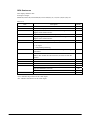
Table of the Contents
Chapter 1.
1.1
1.2
Chapter 2.
2.1
2.1.1
2.1.2
2.1.3
2.1.4
2.1.5
2.1.6
2.1.7
2.1.8
2.1.9
2.1.10
2.1.11
2.2
2.2.1
2.2.2
2.2.3
2.2.4
2.2.5
2.2.6
2.2.7
2.2.8
2.3
2.3.1
2.3.2
2.4
2.4.1
2.4.2
2.4.3
2.4.4
2.5
2.5.1
2.5.2
2.5.3
2.5.4
2.6
2.6.1
2.6.2
2.6.3
2.6.4
2.7
2.7.1
Editorial Record
Preview
Product Overview
Model by Feature
Available Options
Functions
Basic Specifications
Windows Mobile® 6.5
Display
Touch Panel
Keys
Audio
Buzzer Sound
Memory Management
Reset
Memory Corruption Check
LED
Vibration
CMOS Imager
Basic Specifications
Scanning Method
Scanning Parameters
Scan Result Notification
Expanded Features
Configuration File
Concurrent Use with Other Device
Process of Image
Digital Camera
Basic Specifications
Capturing Images
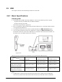
Near Field Communication (NFC)
Basic Specifications
Communication Functions
Expanded Features
Power Control
Secure Application Module (SAM)
Basic Specifications
Power Control
Communication Functions
Processing During Suspend and Resume
USB
Basic Specifications
COM Port
Product ID
Vendor ID
Bluetooth
Basic Specifications
2
6
7
8
8
9
10
10
10
11
14
15
23
24
25
27
29
30
33
34
34
37
39
41
42
50
56
56
57
58
60
67
67
68
72
72
73
73
73
73
75
76
76
78
78
78
79
79
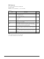
2.7.2
2.7.3
2.7.4
2.7.5
2.7.6
2.8
2.8.1
2.8.2
2.8.3
2.8.4
2.8.5
2.8.6
2.9
2.9.1
2.9.2
2.10
2.10.1
2.10.2
2.11
2.11.1
2.11.2
2.11.3
2.11.4
2.11.5
2.12
2.12.1
2.12.2
2.12.3
2.12.4
2.12.5
2.12.6
2.13
2.13.1
2.13.2
2.13.3
2.13.4
2.13.5
2.13.6
2.13.7
2.13.8
2.13.9
2.13.10
2.14
2.14.1
2.14.2
2.14.3
2.14.4
Chapter 3.
3.1
3.2
Communication Profiles
Security
COM Port
Simultaneous Use with WLAN
Communication Range
WLAN
Basic Features
Expanded Features
Roaming
Zeroconfig
Channels
WLAN Setting with Configuration File
WWAN
Basic Specifications
Available Features
GPS Positioning Function
Basic Specifications
GPS Function API
MCR
Read, Analysis Function
Read Completion and Error Notification
Designating Track
Automatic Power OFF
Raw Data Retrieve
Printer
Printing Functions
Detections
Error Control
Registry Information
ESC Commands
Guide Line to Producing Formed Paper
Power Control
Monitoring Low Voltage
Power ON Factors
Power OFF Factors
Control on Power Key
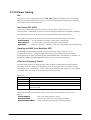
Power Saving
CPU Power Mode
Virtual OFF by Application
Virtual OFF by System
Charging/Supplying the Power
Temperature Control
Security
Setting Password for Terminal
Setting Encryption on SD Card
Setting Individual ID
Setting Distributor ID
Control Panel Applets
Clock & Alarms
Lock
3
80
81
81
82
83
84
84
85
86
87
88
88
95
95
96
97
97
98
106
106
107
108
109
109
110
110
137
144
146
147
149
150
150
152
153
154
155
157
159
162
162
162
163
163
163
163
163
164
167
169
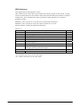
3.3
3.4
3.5
3.6
3.7
3.8
3.9
3.10
3.11
3.12
3.13
3.14
3.15
3.16
3.17
3.18
3.19
3.20
3.21
3.22
3.23
3.24
3.25
3.26
3.27
3.28
3.29
3.30
3.31
3.32
3.33
3.34
3.35
3.36
3.37
Chapter 4.
4.1
4.2
4.3
4.4
4.5
4.6
4.7
4.8
4.9
4.10
4.11
4.12
4.13
4.14
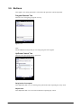
Power
Sounds & Notifications
Today
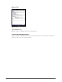
Buttons
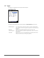
Input
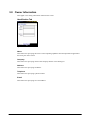
Owner Information
About
Backlight
Buzzer
Certificates
CPU Speed
Customer Feedback
Encryption
Error Reporting
External GPS
Imager Setting
Managed Programs
Memory
Setting Printer
Regional Settings
Remove Programs
Screen
Task Manager
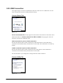
USB Connection
Version Info
Beam
Connections
Domain Enrollment
Network Cards
USB to PC
WAN Settings
Wireless Manager
Wireless Configuration
WLAN Power
WLAN Settings
Application Programs
Today
Games
ActiveSync
Backup Tool
Calculator
Calendar
Contacts
Copy Devices
Display Demo
File Explorer
FLCE
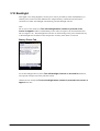
Getting Started
GPS Information
Image Scanner Demo
4
171
172
173
175
177
179
181
183
186
187
189
190
191
192
193
195
203
204
205
211
214
215
217
218
220
221
222
223
224
225
226
243
244
245
246
251
253
254
255
256
262
263
265
266
269
270
271
272
273
277
4.15
4.16
4.17
4.18
4.19
4.20
4.21
4.22
4.23
4.24
4.25
4.26
4.27
4.28
4.29
4.30
4.31
4.32
4.33
4.34
4.34.1
4.34.2
4.34.3
Chapter 5.
5.1
5.2
5.3
5.4
5.5
Chapter 6.
6.1
6.2
6.3
6.4
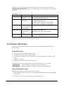
Image Scanner Read
Internet Explorer
Internet Sharing
Messaging
Messenger
Mobile Camera
NetSearch
NFC Demo
Notes
Notification Demo (Buzzer / Vibration)
Phone
Pictures & Videos
Printer Demo
Remote Desktop Mobile
Search
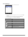
Task Manager
Tasks
Windows Live
Windows Media
LogViewer
Overview
Terminal Log Viewer
Customization
Utilities
FCHKCE
Auto Setup
TextEditor
CT Client
DSKClean
PC Application Programs
ActiveSync
Windows Mobile Device Center (WMDC)
LMWIN
FCHK
281
282
283
284
291
292
294
298
301
303
303
304
307
308
309
310
311
312
313
316
316
319
329
330
330
331
332
333
334
336
336
336
337
337
No part of this document may be produced or transmitted in any form or by any means, electronic
or mechanical, for any purpose, without the express written permission of CASIO Computer Co.,
Ltd. in Tokyo Japan. Information in this document is subject to change without advance notice.
CASIO Computer Co., Ltd. makes no representations or warranties with respect to the contents or
use of this manual and specifically disclaims any express or implied warranties of merchantability
or fitness for any particular purpose.
© 2012 CASIO Computer Co., Ltd. All rights reserved.
5
Editorial Record
Manual
Version no.
1.00
Date edited
Page
March 2012
all
Content
Original version
6
Preview
The features and specifications described in this reference manual give you the functional detail of
the software integrated in the IT-9000 series handheld terminals with Microsoft Windows
Mobile® Version 6.5 OS.
7
1. Product Overview
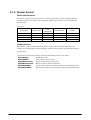
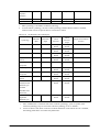
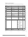
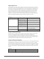
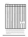
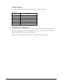
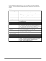
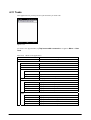
1.1 Model by Feature
The major features integrated in each model of the IT-9000 series are shown below.
Table 1.1
Model no.
Printer
Image
Scanner
Yes
Yes
Yes
Yes
Yes
Yes
Yes
MCR
W-WAN
GPS
Yes
Yes
Yes
Yes
Yes
-
W-LAN
(802.11 b/g)
Yes
Yes
Yes
Yes
Yes
Yes
Yes
Yes
Yes
Yes
Camera
NFC
Extnsion
Slot
Yes
-
IT-9000-05E
Yes
Yes
IT-9000-05E-CN
Yes
Yes
IT-9000-G05E
Yes
Yes
IT-9000-GMC25E
Yes
Yes
Yes
Yes
IT-9000-25E
Yes
Yes
IT-9000-G25E
Yes
Yes
IT-9000-GC25E
Yes
Yes
Yes
*1
IT-9000-GM35E
Yes
Yes
Yes
IT-9000E-MC25E
Yes
Yes
Yes
Yes
IT-9000E-C25E
Yes
Yes
Yes
Notes:
•
*1 82.55mm Other model=80mm
•
Model with “-CN” at the end of its model number is for China.
•
Model with “-MC25E/-C25E” at the end of its model number is for USA and Canada.
8
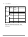
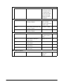
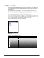
1.2 Available Options
The following dedicated options are available for IT-9000 series.
Table 1.2
Option
Cradle
Battery
Battery charger
Product
USB Cradle
Ethernet Cradle
Battery Pack
Dual Battery
Charger
Cradle-type Battery
Charger
Car Mounted-type
Battery Charger
AC adaptor
(for HA-L60IO, HA-L62IO,
HA-L30CHG,)
USB cable
Cable
Model no.
HA-L60IO
HA-L60IO-CN
HA-L62IO
HA-L62IO-CN
HA-G20BAT
Remark
HA-G32DCHG
HA-L30CHG
HA-L30CHG-CN
HA-H35CHG
With Car power Cable
AD-S42120C-N5
Without power cable accompanied
DT-380USB-A
To connect cradle to PC
USB cable
(Host)
HA-L80USBH
HA-L80USBH-CN
USB cable
(Client)
USB-Serial cable
HA-L81USBH
HA-L81USBH-CN
HA-L82RSC
HA-L82RSC-CN
Note:
“-CN” attached at the end of model number denotes that the model is dedicated for the final
destination of China. A note about compliance with the Chinese “RoHS” requirement
promulgated by the Ministerial Decree No. 39 is accompanied in the carton box; the RoHS
compliant seal is affixed on the body and the seal of the packing material recycle marking is
affixed on the carton box.
9
2. Functions
This chapter describes about detailed specifications of the functions implemented in the terminal
and the dedicated options.
2.1 Basic Specifications
This chapter describes about the basic specifications of the functions implemented in the terminal.
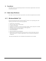
2.1.1 Windows Mobile® 6.5
The terminal integrates Microsoft® Windows Mobile® Version 6.5 as its operating system. The
operating system features with the following capabilities.
•
•
•
•
•
•
•
•
•
Windows CE 5.0 based kernel
Improved virtual memory control method
UI with new touch panel
MyPhone service which can synchronize and share schedule, contacts, and pictures via WEB
Marketplace which can search and purchase mobile application
InternetExploreMobile6 (based on IE6.0)
RemoteDesktopMobile
Open environment to easy development
High speed processing possible due that many programs such as the OS module, the basic
driver, and font file, etc. required for applications to run are transferred to the RAM from
NAND disk.
Other Microsoft applications such as PocketWord and PocketExcel are not bundled.
10
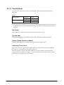
2.1.2 Display
Basic Specifications
The VGA (480 x 640 dots) display mode is supported in the terminal.
Table 2.1
Specification
Display size
(Large)
Display size
(Standard)
X direction
Y direction
X direction
Y direction
65,536 colors 2-way TFT LCD* (16 bpp, Red: 5 bits, Green: 6 bits, Blue: 5 bits)
480 dots
640 dots
240 dots
320 dots
Switching VGA and QVGA
The Windows Mobile OS integrated in devices including the Casio IT-9000 cannot switch the
display mode, from VGA to QVGA and vice versa, due to Microsoft requirement. This limits that
the display resolution with the OS is VGA mode only.
However, the Windows Mobile OS features extended display function which offers various
display modes detailed in the table.
Table 2.2
Specification of Display
Resolution in Application
Not specified
Yes,
QVGA
specified
VGA
Display condition
Display in QVGA mode with doubled size in X and Y directions.
Display in QVGA mode with doubled size in X and Y directions.
Display in VGA mode as is.
Backlight Brightness
•
•
•
•
•
•
Brightness of the backlight can be adjusted at the Control Panel, or using the relevant
functions of the System Library.
Brightness setting can be made in one of nine grades for power source either when the power
is provided by an external power supply (by AC Adaptor connected via cradle, or AC Adaptor
directly connected) or when the power is provided by the installed lithium-ion battery pack.
Brightness setting can be made in application by using ExtEscape()API function.
If the brightness is set to 1 (minimum), the backlight is turned off.
With the power source by the installed lithium-ion battery pack, the system automatically
controls the brightness at 50% level to curve power consumption. This does not require the
running application to aware of the brightness control.
The default is 9 (maximum) when an external power source is used or 7 when the lithium-ion
battery pack is used.
11
The functions of the System Library relevant to the Backlight Brightness are as follows.
SysGetBLBattery
: Retrieves brightness of the screen when the power is supplied by battery
pack.
SysSetBLBattery
: Sets up brightness of the screen for the power source supplied by battery
pack.
SysSetBLExpower
: Sets up brightness of the backlight for the power source supplied by
external power.
SysGetBLExpower : Retrieves brightness of the backlight when the power is supplied by
external power.
SysGetBLMaximum : Retrieves the maximum value of brightness for the backlight.
Backlight Auto Dimming
The brightness at the Control Panel can be used to set up whether or not the Auto Dimming
function is used and the waiting time until when dimming begins. The auto dimming is set effect
only when the power is provided by the lithium-ion battery pack. It will not activate when an
external power supply is used.
• If the terminal is left unused in idle state - absolutely no key input is made - while the power is
turned on, the backlight will be automatically dimmed to save the power after a given period
of time has been elapsed.
• While the terminal is being in the auto dimmed state, pressing key disables the auto dimming
function and then resumes the ordinary brightness.
• While the Auto Dimming function has been set effect, the brightness can be set in one of eight
grades. The default is 3. During the Auto Dimming function being set effect, the brightness
cannot be set any brighter than the brightness illuminated by the backlight. The defaults are
“Enable the auto dimming function” and “1 minute” for waiting time period until when the
Auto Dimming function activates.
Auto Backlight OFF
The brightness at the Control Panel can be used to set up whether or not the Auto Backlight OFF
function will be used and the waiting time until when the Auto Backlight OFF function activates.
The Auto Backlight OFF function is operable for both when the power is provided by an external
power source and when it is provided by the lithium-ion battery pack.
•
•
•
If the terminal is left unused in idle state - absolutely no key input is made - with the power
being turned on, the backlight will be automatically turned off to save the power.
When the terminal is in the Auto Backlight OFF state, pressing a key disables the Auto
Backlight OFF function and resumes the ordinary brightness.
While the power is being provided by the lithium-ion battery pack and both the Auto
Dimming function and the Auto Backlight OFF function have been set effect, either one of the
functions with preset time period shorter than the other will have the priority. The default is
“Enable the Auto Backlight OFF function” and “5 minutes for the waiting time” until when
the Auto Backlight OFF function activates.
12
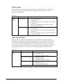
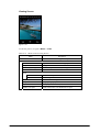
Flipping Display Screen
Flipping display screen at 90, 180 or 270 degree is supported.
• The relevant functions of the System Library can be used to set up an angle to flip the screen
in application.
• With ChangeDisplaySettingEx() API function, flipping display screen at 90, 180 or 270
degree can be set in application.
See Microsoft Help for detail about ExtEscape() and ChangeDisplaySettingEx() API
functions.
The functions of the System Library relevant to the Flipping Display Screen are as follows.
SysSet180Rotate : Sets up angle to flip the screen.
SysGet180Rotate : Retrieves the status of angle for flipping the screen.
Restrained Backlight Brightness by Temperature Sensor
When temperature in the terminal becomes extremely high, the backlight brightness is restrained.
There are two stages to restrain the brightness. In first stage, setting up the brightness is limited to
the range of 1 to 7 instead of the range 1 to 9. In second stage, setting up the brightness is further
restrained to the range of 1 to 5.
If the brightness set in ordinary brightness or in a specific range with the Auto Dimming function
(effect only when power source is supplied by the lithium-ion battery pack) is any brighter than
the limited range affected by high temperature, the brightness is automatically adjusted to the
maximum brightness in the limited range. However, the brightness resumes automatically its
brightness when the temperature becomes lower.
13
2.1.3 Touch Panel
An input can be made to any portion of the touch panel. The touch panel has the following
resolutions.
Table 2.3
High Resolution
Resolution
•
X direction
Y direction
X direction
Y direction
480 dots
640 dots
240 dots
320 dots
Capturing touch coordinates in X and Y directions and controlling the pointing are possible by
application. Prior to using the touch panel for the very first time, calibrating the touch panel is
required.
Tap Sound
The Control Panel can be used to set up tap sound in mute, low or loud.
Tap and Hold
By tapping and holding a specific object on the screen, the related pop-up menu appears.
Flipping Touch Panel Coordinates
When the screen flips, the coordinates of the touch panel also flip in unison.
Calibrating Touch Panel
Calibration on the touch panel can be initiated either using the Welcome wizard appeared after
disk clean or by simultaneously pressing Fn and 4 keys.
The touch panel may require a periodical calibration if it slips off due to aged deterioration,
voltage fluctuation, temperature change, etc. If it occurs on the screen of your terminal, perform
the calibration by initiating one of the methods.
14
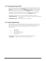
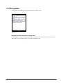
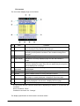
2.1.4 Keys
Keyboard Layout
The following is the keyboard layout employed in the terminal.
Figure 2-1
15
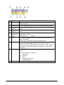
Key Assignments
The following are the key codes and function assignments.
Table 2.4
KEY
Fn
Control keys
Input mode
Operation
----
Character input mode
C
Function mode
Character input mode
BS
Function mode
MENU
Character input mode
Function mode
ENT
Character input mode
Function mode
←
Character input mode
Function mode
→
Character input mode
Function mode
(hyphen
)
Table 2.5
KEY
F1
Character input mode
Function mode
Function keys
Input mode
Character input mode
Function mode
Specialized key operation (toggle).
1
A
a
F
1
A
a
F
1
A
a
F
1
A
a
F
1
A
a
F
1
A
a
F
1
A
a
F
1
A
a
F
Remarks
Fn mode is
released when a
key input is made.
Performs as ESC key.
Performs as ESC key.
Performs as ESC key.
NOP
Deletes one character to the left.
Deletes one character to the left.
Deletes one character to the left.
NOP
Perform as MENU key.
Perform as MENU key.
Perform as MENU key.
Start the application.
Performs as Enter key.
Performs as Enter key.
Performs as Enter key.
NOP
Perform as “Cursor left key”.
Perform as “Cursor left key”.
Perform as “Cursor left key”.
NOP
Perform as “Cursor right key”.
Perform as “Cursor right key”.
Perform as “Cursor right key”.
Feed the printer paper.
Performs as - key.
Performs as - key.
Performs as - key.
Switch over the input mode.
Numeric→ Alphabet(U)→
Alphabet(L)
Operation
Performs as F1 key.
Performs as F1 key.
Performs as F1 key.
Performs as Shift and F1 key.
16
Remarks
F2
Character input mode
F3
Function mode
Character input mode
F4
Function mode
Character input mode
Function mode
Table 2.6a Program keys
KEY
Input mode
Program Character input mode
Key L
Program
Key R
Function mode
Character input mode
Function mode
1
A
a
F
1
A
a
F
1
A
a
F
Performs as F2 key.
Performs as F2 key.
Performs as F2 key.
Performs as Shift and F2 key.
Performs as F3 key.
Performs as F3 key.
Performs as F3 key.
Performs as Shift and F3 key.
Performs as F4 key.
Performs as F4 key.
Performs as F4 key.
Performs as Shift and F4 key.
1
A
a
F
1
A
a
F
R Program key
R Program key
R Program key
R Program key
L Program key
L Program key
L Program key
L Program key
Operation
17
Remarks
Table 2.7
Key
00
Ten key
Input mode
Character input mode
1
A
a
0
Function mode
Character input mode
1
Function mode
Character input mode
2
Function mode
Character input mode
3
Function mode
Character input mode
4
Function mode
Character input mode
5
Function mode
Character input mode
6
Function mode
Character input mode
7
Function mode
Character input mode
8
Function mode
Character input mode
9
Function mode
Character input mode
F
1
A
a
F
1
A
a
F
1
A
a
F
1
A
a
F
1
A
a
F
1
A
a
F
1
A
a
F
1
A
a
F
1
A
a
F
1
Operation
Performs as 00 key.
Performs as “-_ / ^\&=+$%#* space
€” keys.
Performs as “-_ / ^\&=+$%#* space
€” keys.
NOP
Performs as 0 key.
Performs as “0123456789” keys.
Performs as “0123456789” keys.
Displays SIP or does not display.
Performs as 1 key.
Performs as “?!()<>[]{}@” keys.
Performs as “?!()<>[]{}@” keys.
Turns on or off the backlight.
Performs as 2 key.
Performs as “A”, ”B” and ”C” keys.
Performs as “a”, ”b” and ”c” keys.
Turns on or off the key backlight.
Performs as 3 key.
Performs as “D“, ”E” and ”F” keys.
Performs as “d”, ”e” and ”f” keys.
NOP
Performs as 4 key.
Performs as “G”, ”H” and ”I” keys.
Performs as “g”, ”h” and ”i” keys.
Start the screen of Mouse Properties
Performs as 5 key.
Performs as “J”, ”K” and ”L” keys.
Performs as “j”, ”k” and ”l” keys.
Darkens the backlight.
Performs as 6 key.
Performs as “M”, ”N” and ”O” keys.
Performs as “m”, ”n” and ”o” keys.
Brightens the backlight.
Performs as 7 key.
Performs as “P”, ”Q”, ”R” and ”S”
keys.
Performs as “p”, ”q”, ”r” and ”s” keys.
Start the application.
Performs as 8 key.
Performs as “T”, ”U” and ”V” keys.
Performs as “t”, ”u” and ”v” keys.
Start the application.
Performs as 9 key.
18
Remark
A
A
.
(Decima
l point)
Function mode
Character input mode
Function mode
F
1
A
a
F
Performs as “W”, ”X”, ”Y” and ”Z”
keys.
Performs as “w”, ”x”, ”y” and ”z”
keys.
Start the application.
Performs as “.” key.
Performs as “@.,”’`:;~|” keys.
Performs as “@.,”’`:;~|” keys.
Performs as “-” key.
19
Switch Over Key Input Mode
The “Fn”+”-“ key on the keyboard can be used to change the key input mode.
The functions of the System Library relevant to the “Key Input Mode Switchover” are as follows.
SysSetEnableKeyMode : Sets up “Enable” or “Disable” for key mode transition when the
key input mode is changed
SysGetEnableKeyMode : Retrieves the status of “Enable” or “Disable” for key mode
transition when the key input mode is changed.
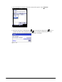
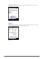
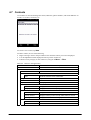
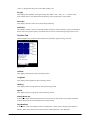
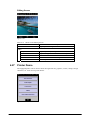
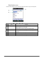
Indication of Key Input Mode
Key input mode currently specified appears in the Title bar. The modes that can be displayed are
“1” as numeral, “A” as alphabets in uppercase letter, and “a” as alphabets in lowercase letter.
Figure 2-2
Turnover Key Auto Confirmation
After pressing a turnover key, if the preset time period has been elapsed from the time when the
turnover key is released, the turnover character input will be automatically made. The Control
Panel can be used to set up “Enable” or “Disable” for the auto confirmation on the turnover
character input and to set up the time period until when its confirmation is made.
Key Repeat
Continuously pressing any one of the “0” to “9”, “←” and “→” keys repeats the key input.
Key Click Sound
The key click sound is generated when a key is pressed. However, it is not generated when the key
is released or in mid-course of repeating the key input. The Control Panel can be used to set up the
sound to mute, low or loud.
20
Enabling or Disabling Fn Key operation
For keys that perform specialized operations while the key input mode has been set to Function
mode, “Enable” or “Disable” can be set on each individual key in the registry below to control the
operations.
[HKEY_LOCAL_MACHINE\HARDWARE\DEVICEMAP\KEYBD]
Or, using the SysSetFnKeyOperation function of the System Library can achieve the same
control operation explained above.
Table 2.8
Key
Setting Value
Meaning
DisableFn9
dword: 0 or 1
Enable or Disable
DisableFn8
dword: 0 or 1
Enable or Disable
DisableFn7
dword: 0 or 1
Enable or Disable
DisableFn6
dword: 0 or 1
Enable or Disable
DisableFn5
dword: 0 or 1
Enable or Disable
DisableFn4
dword: 0 or 1
Enable or Disable
DisableFn3
dword: 0 or 1
Enable or Disable
DisableFn2
dword: 0 or 1
Enable or Disable
DisableFn1
dword: 0 or 1
Enable or Disable
DisableFn0
dword: 0 or 1
Enable or Disable
DisableFnMenu
dword: 0 or 1
Enable or Disable
The functions of the System Library relevant to the “Enabling or Disabling Fn Key” are as
follows.
SysSetFnKeyOperation : Sets up “Enable” or “Disable” for the Fn key operation.
SysGetFnKeyOperation : Retrieves “Enable” or “Disable” status for the Fn key operation.
Function Mode Notification
When the Fn key is pressed, the WM_USER+0x502 message is issued to application. This enables
the application to detect whether the Function mode has been set up enabled or disabled.
Enable or Disable the Key Input Mode Switchover.
The System Library can be used to make the setting on “Enable” or “Disable” for switching over
the key input mode in application.
The functions of the System Library relevant to the “Enable or Disable the Fn Key” are as
follows.
SysSetFnKeyLock : Sets up “Enable” or “Disable” for the Fn key to activate.
SysGetFnKeyLock : Retrieves “Enable” or “Disable” status for the Fn key to activate.
Fn and “-“ Keys Notification
When the Fn and “-“ keys are pressed, the WM_USER+0x506 message is issued to application.
Using this notification, the application can detect whether the key input mode has been changed.
21
Enable or Disable Key Locks
The System Library can be used to enable or disable the operations of keys except for the Power
and Program keys.
The functions of the System Library relevant to the “Permit or Prohibit Key Locks” are as
follows.
SysSetAllKeyLock : Sets up “Enable” or “Disable” for lock with specified key.
SysGetAllKeyLock : Retrieves “Enable” or “Disable” status for lock with specified key.
Keys User Can Set
Initiating application
The following registry can be used to assign any application to the Fn+7, Fn+8, Fn+9 and
Fn+Menu keys.
[HKEY_LOCAL_MACHINE\HARDWARE\DEVICEMAP\KEYBD]
Table 2.9
Key
Fn7LaunchPath
Fn8LaunchPath
Fn9LaunchPath
FnMENULaunchPath
Setting Value
sz: the full path of target application to initiate.
sz: the full path of target application to initiate.
sz: the full path of target application to initiate.
sz: Target application in full path to initiate
• Setting Key Codes
The System Library can be used to assign any key code to all the keys except the Fn key. Setting
“Enable” or “Disable” for assigning key code is possible using the System Library or at the
Control Panel.
The functions of the System Library relevant to the “Setting Key Codes” are as follows.
SysSetNormalUserDefineKey : Sets up key codes (in normal mode).
SysGetNormalUserDefineKey : Retrieves key codes (in normal mode).
SysSetUserDefineKey
: Sets up user defined keys
SysGetUserDefineKey
: Retrieves user defined keys
•
The key codes after setting are valid only when the numeral input mode is set effect.
22
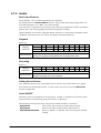
2.1.5 Audio
Basic Specifications
WAV playback, voice recording and playback are supported.
By using the Microsoft SoftwareMixer function, output sounds from multiple applications can
be mixed and output (in 44.1 KHz, 16-bit stereo mixing).
Voice Recorder is integrated in the terminal as the sound system application to make it possible to
perform WAV file streaming playback and local file playback in HTTP.
Audio and Buzzer use the same integrated speaker, therefore it is not possible to playback Audio
and Buzzer sound at the same time. In this case, Buzzer sound has the priority.
Playback
Table 2.10
Sampling
frequencies
Stereo/Monaural
KHz
8
11.025
12
16 22.05
24
32
44.1
Mono
Yes
Yes
Yes Yes
Yes
Yes Yes Yes
Stereo
Yes
Yes
Yes Yes
Yes
Yes Yes Yes
Sampling frequencies other than those above are not supported.
8-bit or 16-bit
In reality, the integrated monaural speaker does not output sound in stereo.
48
Yes
Yes
KHz
8
11.025
12
16
22.05 24
Monaural Yes
Yes
Yes Yes
Yes
Yes
Sampling frequencies other than those above are not supported.
8-bit or 16-bit
Monaural sound input only via the microphone.
48
Yes
Recording
Table 2.11
Sampling
frequencies
Stereo/Monaural
32
Yes
44.1
Yes
Setting Sound Volume
The “Volume & Sound” at the Control Panel can be used to set up sound volume in six grades
from loud to low and ON/OFF of mute. A sound volume also can be set up using Win32 API
function in application.
Audio ON/OFF
The audio system can be disabled to save the power. “Enable” or “Disable” for the audio system
in the terminal is controlled using the System Library in application.
The functions of the System Library relevant to the Audio ON/OFF are as follows.
SysAudioOff
: Turns off the audio virtually with the audio turned off.
SysAudioOn
: Turns on the audio virtually with the audio turned on.
SysGetAudioPowerState : Retrieves “Enable” or “Disable” status for turning off the audio
virtually.
23
2.1.6 Buzzer Sound
Basic Specifications
The buzzer sound in various modes such as scanning confirmation, alarm, warning, and other
available sounds can be output via the integrated speaker. The sounds have four attributes and
default values.
Table 2.12
Sound Mode
Alarm
Warning
Scan end
User designated
Frequency (Hz)
3500
3000
3300
--
Time
(millisecond)
150
100
75
--
Individual Mute
Attribute
ON or OFF
ON or OFF
ON or OFF
ON or OFF
B_ALARM
B_WARNING
B_SCANEND
B_USERDEF
Setting Volume
The “Buzzer” at the Control Panel can be used to set up volume in three grades from loud,
medium, low and ON/OFF of mute. Setting the volume is also possible using the System Library
in application.
The functions of the System Library relevant to the Setting Volume are as follows.
SysPlayBuzzer
: Sounds the buzzer.
SysStopBuzzer
: Turns off the buzzer’s sound.
SysSetBuzzerVolume : Sets up sound volume of the buzzer.
SysGetBuzzerVolume : Retrieves sound volume of the buzzer.
SysSetBuzzerMute
: Sets up sound volumes for all the parameters and individual mutes.
SysGetBuzzerMute
: Retrieves the statuses of all the sound volumes and individual mutes.
24
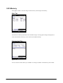
2.1.7 Memory Management
The high speed and large capacity RAM (MobileDDR 256MB) and FlashROM (OneNAND Flash
256MB) are integrated in the terminal.
Although RAM has been used for RAM XIP (for OS), program memory (for program files to run)
and object store (for storage of work data) in the previous Casio handheld terminals introduced in
the past, non-volatile memory (FlashROM) is integrated to the Root folder in the terminal.
Your observation is required for the new method adopted in the terminal to manipulate the
memory different from the previous Casio handheld terminals.
Notes:
• Patch file, program file and data are not lost even if the battery pack runs down. It is no longer
needed to back up object store in the RAM.
• Although performing a full reset initializes object store (RAM) in the previous Casio handheld
terminals, the new method initializes the RootDisk in the terminal.
• Formatting the UserDisk initializes registry, program file, and data to their factory defaults.
• UserDisk is divided into two blocks, RootDisk and FlashDisk. In the RootDisk, system file,
registry, and patch driver, etc. are stored while backup data of backup tool and recovery tool
are stored in the FlashDisk. This makes recovery of data from the FlashDisk possible in case
of malfunction on the system.
RAM
The integrated RAM with a total capacity of 256MB is used for the below purposes.
DriverGlobal and buffer : Work area for driver, etc.
OS area
: Area to deploy the OS to run.
Program memory
: Program execution area including work area for the OS.
•
•
•
•
•
The DriverGlobal is a fixed area allocated for work area of drivers. The camera buffer used
in the digital camera integrated models deploys captured image data temporarily.
The OS files are deployed from the Kernel of the FlashDisk to the RAM in the terminal. This
allows the OS to run quickly on the RAM. However, it takes time to deploy the OS files from
the FlashDisk to the RAM in case when booting takes place after a full reset is performed or
the lithium-ion battery runs down.
Object store equivalent of the RAM disk in the previous Casio handheld terminals is no longer
integrated. If files are copied to Root and Windows folder under “My device” folder, this
creates the same files in the UserDisk of FlshROM and secures data without performing
backup in case the lithium-ion battery is not installed.
Although performing a full reset (all memory clear) deletes object store (RAM) in the previous
Casio terminals, it deletes the RootDisk causing registry and system DB to be deleted and to
initialize the system.
This does not allow to change the ratio between program memory and object store at the
Control Panel.
25
FlashDisk
The FlashDisk has a total capacity of 256MB and is used for the below purposes.
Boot area
: Deploys the OS files to the RAM from the OS disk.
OS disk/Kernel : Stores the OS files. Boot loader is deployed in the RAM at time of booting.
User disk
: A disk user can freely use. It comprises the RootDisk which is mounted in
the system root folder and the FlashDisk.
Spare
: A substitution sector of the FlashROM
•
•
•
•
•
In the boot area, boot loader and etc. are stored to deploy the OS files/Kernel into the RAM.
In the OS disk, the OS module, drivers, integrated applications and etc. are stored.
The UserDisk different in its structure from RAM does not require a power to back up data in
the disk, so data is not lost even if the terminal’s memory backup battery runs down.
The FlashDisk is observed as \FlashDisk driver under “My Device” and stores backup data
used to restore the system to the same condition before unstable condition occurs. Data stored
in the FlashDisk for restoration is not deleted by performing a full reset.
Formatting the UserDisk deletes registry, patch files, program files and data, and initializes the
system to the factory default.
Note:
Formatting on the UserDisk is carried out by a dedicated format tool in the Windows folder or by
operating special keys. See the next chapter concerning the special keys operation.
26
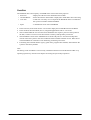
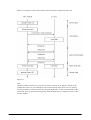
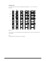
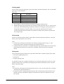
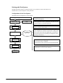
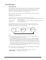
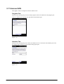
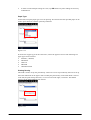
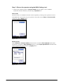
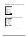
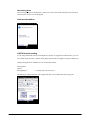
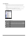
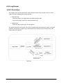
2.1.8 Reset
The role of the boot loader in Windows Mobile (OAL) is to boot the OS after initializing the
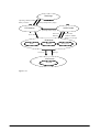
hardware. On the terminal, it is possible to carry out the special performances with special keys
operation as described in the figure below.
BootLoader of IT-9000
BootSelector
(Soft Rest(default))
IPL
OS Loader
(Power + C + Reset)
(Fn + C+ . + Reset)
(Fn + − + ENT + Reset)
OS Clear and Reload
User Disk Clear
Hard Reset
Figure 2-3
To reset the terminal, there are several ways to carry out it. The explanation below describes the
methods to reset the terminal. See also Table 2.13.
Soft Reset
The operation requires pressing the reset switch on the back of the terminal. It initializes the
program memory.
Full Reset
This operation is carried out if Power and C keys are held down at the same time and then the
reset switch is pressed for a period of one second or longer. It initializes RAM and formats the
RootDisk and reloads the OS again from the OS disk to the RAM.
Hard Reset
This operation is carried out if Fn and “-” and ENT keys are held down at the same time and then
the reset switch is pressed. The RAM and Clock (RTC) are initialized and the OS files are
reloaded into the RAM.
27
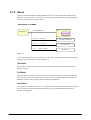
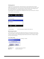
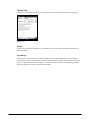
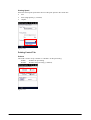
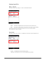
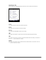
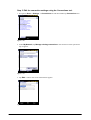
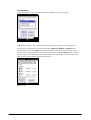
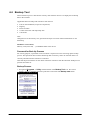
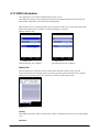
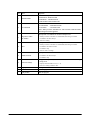
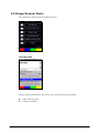
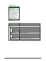
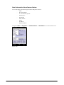
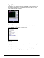
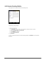
User Disk Clean
This operation is carried out if Fn and C and “.” keys are held down at the same time and then the
reset switch is pressed for a period of one second or longer that formats the RootDisk and
FlashDisk and initializes the RAM to the factory default and then reloads the OS files to the
RAM.
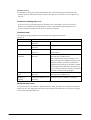
A message (see Figure 2.4 ) to confirm memory initialization appears. The R Program key is used
to confirm the User Disk Clean.
X
X
Figure 2-4
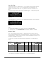
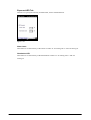
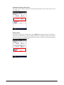
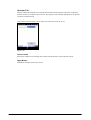
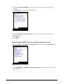
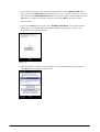
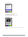
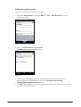
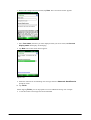
After the R Program key is pressed twice, the UserDisk is formatted and the RAM is initialized to
the factory default (see note).
Figure 2-5
Notes:
• Distributor ID in E2PROM is not cleared by performing the User Disk Clean.
• The utility to carry out the User Disk Clean is available. See “ DSKClean ” for detail.
X
X
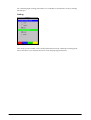
Power-on Reset
This is a state occurred on the terminal after the battery pack and memory backup battery are
demounted and then put back into the terminal and then the Power switch is turned on for the first
time. When the Power switch is turned on in this state, the Boot Loader performs reloading the OS
files (RTC is initialized if it is necessary).
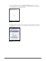
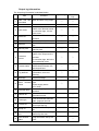
The table shows the respective states and data in the components and devices when the reset
occurs.
Table 2.13
Soft Reset
Full Reset
Hard Reset
User Disk Clean
Power-on Reset
RAM
OS
Program
Memory
Memory
No
Initialize
Reload
Initialize
Reload
Initialize
Reload
Initialize
Reload
Initialize
RootDisk
FlashDisk
Registry
No
Initialize
No
Initialize
No
No
No
No
Initialize
No
No
Initialize
No
Initialize
No
Clock
(RTC)
No
No
Initialize
No
No/Initial
ize
Note:
“No” in the table indicates that the content in memory is not initialized by the reset.
28
E2PROM
Individu Distribut
al ID
or ID
No
No
No
No
No
No
No
No
No
No
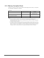
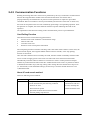
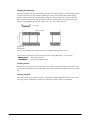
2.1.9 Memory Corruption Check
Checksum is carried out in order to detect whether the OS deployed in the memory is corrupted or
not, and the OS is reloaded if it is necessary.
Table 2.14
On Soft Reset
Confirm the checksum
Carried out
On Full Reset, Hard Reset, User Disk
Clean and Power-on Reset
On Suspend and Resume (see notes)
-
OS load
Carried out when error of
checksum occurs.
Carried out
No
No
Notes:
• The reason that the checksum is not carried out on suspending and resuming is for
high-speed performance. But, memory corruption check is carried out to check if the RAM
is in error status by any reason.
• The RAM corruption check is performed by writing fixed data (0x00 to 0xFF) into a fixed
area (256 bytes area) in the RAM prior to performing the check, and the value written in the
RAM is verified at a time of Resume. If an error is detected, warning message for memory
corruption check is issued, and then reset is performed and the OS files are reloaded.
29
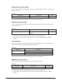
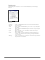
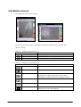
2.1.10 LED
Basic Specifications
There are two LEDs integrated in the terminal, one on the right side (Indicator 2) for the user
notification and the other (Indicator 1) for charging battery complete notification.
Table 2.15
LED
Right side LED
(Indicator 2)
Left side LED
(Indicator 1)
Color
Red
Green
Blue
Orange
Cyan
Magenta
Orange
Green
Red
Description
User notification (alarm), scanning bar code
Scanning bar code complete
Connection established via Bluetooth
Connection established via WLAN, WWAN or GPS
User defined
Connection established via ActiveSync
While charging battery pack.
Charging battery pack is complete.
Charging battery pack in error.
Notes:
• The user notification LED (Indicator 2) on the right side can be used to indicate various
notifications by the OS and other notifications defined by the user.
• All colors available with the LED (Indicator 2) on the right side are indicated with the
System Library.
• The charging battery complete LED (Indicator 1) on the left side cannot be controlled or
manipulated for its ON/OFF state and any other colors with software.
User Notification (Alarm)
This indication mode is used for alarm notification and etc. The LED can be lit for a specific time
with CeSetUserNotification()API function.
Table 2.16
Operating mode
Specification
Blink interval
ON in red for 1 second, OFF for 2 seconds
Continuous ON time
ON for 30 minutes (OFF when VDET is detected.)
Note:
Indication for scanning a bar code has the priority over other indications.
Scanning
This is used for notification of a scanning result which is controlled with the System Library.
Table 2.17
Operating mode
Scanning complete
Scanning in error
Specification
ON in green for a specified period of time, then OFF.
ON in red for a specified period of time, then OFF.
30
Attribute
SCANOK
SCANERR
Bluetooth Connection Status
This is used for notification of Bluetooth connection establishment status which is controlled with
the System Library.
Table 2.18
Status Mode
Specification
Connection established via Bluetooth
ON in blue for 1 second, OFF for 2 seconds
Note:
Indication for scanning a bar code has the priority over other indications.
Attribute
BT
WLAN Connection Status
This is used for notification of WLAN connection establishment status which is controlled with
the System Library.
Table 2.19
Status Mode
Connection established via WLAN
Specification
ON in orange for 1 second, OFF for 2
seconds
Attribute
WLAN
Notes:
• Indication for scanning a bar code has the priority over other indications.
• The indication color for WLAN status is the same with those used for WWAN and GPS
statuses.
User Definition
This indication mode is used for other notifications freely defined by the user. The ON/OFF state
and color to be lit can be controlled with the System Library.
Table 2.20
Status Mode
User definition
Specification
Color selection from red, green, blue, orange, cyan and magenta.
Programmable for ON and OFF time periods
30 minutes (OFF when VDET is detected)
Continuous ON time period
Note:
Indication for scanning a bar code has the priority over other indications.
WWAN Connection Status
This is used for notification of WWAN connection establishment status.
Table 2.21
Status Mode
Specification
Attribute
WWAN established
ON in orange for 1 second, OFF for 2 seconds
WWAN
Notes:
• Indication for scanning a bar code has the priority over other indications.
• The indication color for WWAN status is the same with those used for WLAN and GPS
statuses.
31
GPS Connection Status
This is used for notification of GPS connection establishment status.
Table 2.22
Operation mode
Specification
Attribute
GPS established
ON in orange for 1 second, OFF for 2 seconds
GPS
Notes:
• Indication for scanning a bar code has the priority over other indications.
• The indication color for GPS is the same with those used for WLAN and WWAN statuses.
ActiveSync Connection Status
This is used for notification of ActiveSync connection establishment status which is controlled
with the System Library.
Table 2.23
Status Mode
Specification
Connection established via
ON in Magenta for 0.5 second, OFF for 2.5
ActiveSync
seconds
Note:
Indication for scanning a bar code has the priority over other indications.
Attribute
DISKACCESS
The functions of the System Library relevant to the User Definition are as follows.
SysSetLED
: Sets up “Enable” or “Disable” for turning on the LED.
SysGetLED
: Retrieves “Enable” or “Disable” status for turning on the LED.
32
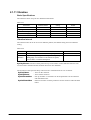
2.1.11 Vibration
Basic Specifications
The vibration can be set up for five different notifications.
Table 2.23
Notification
Alarm
Warning
Bar code scan complete
Wireless incoming signal
User definition
Vibration Pattern
Default
Default
Default
Default
User
Setting
ON or OFF
ON or OFF
ON or OFF
ON or OFF
ON or OFF
Default
OFF
OFF
OFF
OFF
OFF
Vibration Interval
The vibration interval can be set in two different patterns, the default setting and a user defined
setting.
Table 2.24
Pattern
Default
User
definition
Vibration Interval
“ON for 1 second, OFF for 1 second” x ?? [times]
“Specified ON period, Specified OFF period” x ?? [times]
Setting range; 1/16 seconds to 16 seconds for ON period,
1/16 seconds to 1 second for OFF period
Remarks
Maximum no. of times; 20
Maximum no. of times; 20
SysPlayVibrator function of the System Library can be used to control ON/OFF state for each
occasion of the vibration and the vibration interval in user definition.
The functions of the System Library relevant to the “Vibration Interval” are as follows.
SysPlayVibrator
: Turns on the vibration.
SysStopVibrator
: Turns off the vibration.
SysSetVibratorMute : Sets up “Enable” or “Disable” for all the parameters for the vibration
and individual mutes.
SysGetVibratorMute : Retrieves statuses of all the parameters for the vibration and individual
mutes.
33
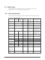
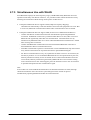
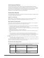
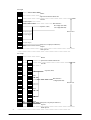
2.2 CMOS Imager
This chapter describes about detailed specifications of the CMOS Imager which is model
dependant. See Table 1.1 for the CMOS Imager integrated models.
X
X
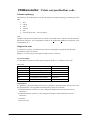
2.2.1 Basic Specifications
The following industrial standard 1D symbologies are supported by the integrated CMOS Imager.
Table 2.25
1D bar code symbologies
Symbology
Minimum
digits
EAN8
Maximum
digits
8 (+2/5)
Check
character
Check
character
output
Always Enable
Enable or
Output format/Add-on
function
2 digits/5 digits added-on
Disable
EAN13
13 (+2/5)
Always Enable
Enable or
UPC-A
12 (+2/5)
Always Enable
Enable or
2 digits/5 digits added-on
Disable
Disable
UPC-E
6 (+2/5)
Always Enable
Enable or
Disable
NS output
2 digits/5 digits added-on
NS output
UPCA conversion
2 digits/5 digits added-on
Code39
1
22
Enable or
Enable or
Output of start/stop bits
Disable
Disable
Full ASCII conversion
Add-on code
Codabar (NW7)
Interleaved 2of5
2
26
Enable or
Enable or
Disable
Disable
Enable or
Output of start/stop bits
4
42
Enable or
Disable
Disable
Code93
1
35
Always Enable
Always Disable
Code128, GS1-128
1
28
Always Enable
Always Disable
Code A/B
1
56
Always Enable
Always Disable
Code C
4
26
Always Enable
Enable or
(ITF)
MSI(Plessey)
Disable
IATA
4
24
Always Enable
Always Disable
Code11
1
40
Always Enable
Always Disable
(2 digits)
DS1 DataBar
14
Always Enable
Always Disable
14
Always Enable
Always Disable
Omnidirectional
(Standard/Truncate
d)
GS1 DataBar
Limited
Continue.
34
GS1 DataBar
1
40
Always Enable
Always Disable
1
28
Always Enable
Always Disable
Always Enable
Always Enable
Expanded
(Standard)
ISBT (note 1)
Code32 (note 2)
9
Notes:
1. ISBT symbology is decoded as Code128 symbology.
2. To read Code32 symbology, set also Code39 symbology enabled. When Code32 is enabled,
Code39 which consists of specific data is converted to Code32.
Table 2.26
2D Stacked Code symbologies
Minimum
digits
Maximum
digits
Check
character
Code49
1
81
PDF417
1
2,000
MicroPDF
1
366
Codablock F
(note1)
EAN8/13
Composite
GS1 Composite
0
200
8
338
Always
Enable
Always
Enable
Always
Enable
Always
Enable
Enable
Check
character
output
Always
Disable
Always
Disable
Always
Disable
Always
Disable
Disable
2
338
UCC/GS1-128
Composite
TLC39
(note2)
GS1 DataBar
omnidirectional
(Stacked type)
included
Standard Omni
directional
GS1 DataBar
Expanded
(Stacked type)
6
2,361
-
279
Always
Enable
Always
Enable
Always
Enable
Always
Enable
Always
Disable
Always
Disable
Always
Disable
Always
Disable
Always
Enable
Always
Disable
Symbology
14
1
20
Output format/Add-on
function
Note:
1. Since Codablock F is a stacked code of the Coda128 symbology, a part of symbol of the
Code128 symbology may be read if the Code128 symbology is set to “Enable”.
2. TLC39 is the bar code which consists of Code39 abd add-on codes. When TLC39 is enabled,
the reading performance of Code39 may deteriorate.
35
Table 2.27 2D Matrix Code symbologies
Symbology
Minimum
digits
Maximum
digits
Check
character
Aztec
QR Code
Micro QR Code
Maxicode
DataMatrix
1
1
1
1
1
2,000
1,500
35
138
1,000
Enable
Enable
Enable
Enable
Enable
Check
character
output
Disable
Disable
Disable
Disable
Disable
HanXin Code
(Chinese
Sensible Code)
1
1000
Enable
Disable
Output format/Add-on
function
ECC000/050/080/100/
140/200
Note:
The maximum numbers of digits listed in the above table apply to cases where the entire
symbology consists of numeric characters only. The maximum number is reduced to two third
(2/3) of each maximum no. of digits for alpha-numeric characters; and reduced to one third (1/3)
for Kanji characters and binary numbers. These are merely reference, and the actual range of
readable symbologies varies according to the conditions (resolution, PCS, etc.) of individual
symbol and the surrounding environment.
36
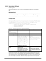
2.2.2 Scanning Method
Ordinary Read
This function reads one bar code at a time and outputs the data. Ordinary, this read method is
used.
Multi-step Read
This function continuously performs decoding as long as one of the R/L Trigger keys is held down.
Once bar codes are decoded they are not read any more. This function is useful for reading all bar
codes without repeating the same action when more than one bar code is printed on one slip.
Package Read
This function outputs the read result retrieved from more than one bar code in a package. With the
multi-step read function, once bar codes are decoded they are not read any more. This is useful for
handling multiple pieces of bar code data. However, if any of the following unfavorable
conditions occur, all the bar codes may not be read in one capture:
The objective bar code of read is not contained in the captured image.
The focus is not sharp enough.
The exposure is not correct.
Table 2.28 Difference between Multi-step and Package Reads
Performance
Multi-step Read Mode
Package Read Mode
Maxi. no. of bar codes to
10
10
read
(Max. no. of read steps)
Max. no. of digits to read 4,095
4,095 (see note below.)
Total no. of digits to read 4,095 x 10 = 40,950
4,095
Read method
Continuously reads the specified
Multiple bar codes are read in a
number of bar codes as long as
single scan.
the Program key is held down.
Neither the buzzer sounds nor the
Different from Package read in
LED turns on until the specified no.
which multiple bar codes are read of bar codes has been read.
at a single scan, a single kind of a
symbol will be continuously read
through multi read steps. If one
bar code is read, the buzzer
sounds and the LED turns on.
Recommended method
This mode is suitable in the
This mode is suitable in the following
of use
following cases:
case:
If the bar code has many digits.
If multiple bar codes with small
If the target bar codes are spaced. number of digits are adjacent to one
To positively confirm a read.
another.
Note:
The terminal is designed so that a maximum of 10 bar codes or 4,095 digits of bar codes Can be
read. However, it is not recommended for the user to use the package read mode for reading bar
codes consisting of a large number of digits. If the number of bar codes is greater than 4, or if the
total number of digits is greater than 100, use the multiple-step read mode as much as possible.
37
The functions of the Imager Library relevant to the Scanning Method are as follows.
IMGSetDecodeMode
: Sets up scanning mode.
IMGGetDecodeMode
: Retrieves the scanning mode.
IMGWaitForDecode
: Carries out decoding symbol.
IMGWaitForDecodeRaw : Carries out decoding symbol including its binary data.
38
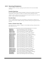
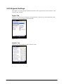
2.2.3 Scanning Parameters
Condition that allows scanning a symbology in specific modes can be set for each readable
symbology.
Readable Symbology
Bar code symbologies that are enabled or disabled for scanning can be specified. If only specific
symbologies are to be scanned, set “Enable” for scanning on these symbologies only and
“Disable” on other symbologies. This reduces decode processing time and lowers error rate. The
default is “Enable scanning on all the symbologies”.
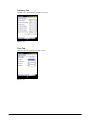
Readable Digits
The no. of readable digits can be set for each symbology. If only specific no. of digits is to be
scanned, specify it for each readable symbology. This reduces decode processing time and lowers
error rate.
Enable or Disable Check Digit
Check digit can be set to “Enable” or “Disable” for each readable symbology. Setting the check
digit will lower error rate.
The functions of the Imager Library relevant to the Scanning Parameters are as follows.
IMGSetAztec
: Sets up decode options for Aztec symbology.
IMGGetAztec
: Retrieves the decode options for Aztec symbology.
IMGSetCodabar
: Sets up decode options for Codabar symbology.
IMGGetCodabar
: Retrieves the decode options for Codabar symbology.
IMGSetCodablock : Sets up decode options for Codablock F symbology.
IMGGetCodablock : Retrieves the decode options for Codablock F symbology.
IMGSetCode11
: Sets up decode options for Code11 symbology.
IMGGetCode11
: Retrieves the decode options for Code11 symbology.
IMGSetCode128
: Sets up decode options for Code128 symbology.
IMGGetCode128
: Retrieves the decode options for Code 128 symbology.
IMGSetCode32
: Sets up decode options for Code32 symbology.
IMGGetCode32
: Retrieves the decode options for Code32 symbology.
IMGSetCode39
: Sets up decode options for Code39 symbology.
IMGGetCode39
: Retrieves the decode options for Code39 symbology.
IMGSetCode49
: Sets up decode options for Code49 symbology.
IMGGetCode49
: Retrieves the decode options for Code49 symbology.
IMGSetCode93
: Sets up decode options for Code93 symbology.
IMGGetCode93
: Retrieves the decode options for Code93 symbology.
IMGSetComposite : Sets up decode options for Composite symbology.
IMGGetComposite : Retrieves the decode options for Composite symbology.
IMGSetDataMatrix : Sets up option settings for DataMatrix symbology.
IMGGetDataMatrix : Retrieves the decode options for DataMatrix symbology.
IMGSetEAN13
: Sets up decode options for EAN13 symbology.
IMGGetEAN13
: Retrieves the decode options for EAN13 symbology.
39
IMGSetEAN8
IMGGetEAN8
IMGSetHX
IMGGetHX
IMGSetIATA
IMGGetIATA
IMGSetITF
IMGGetITF
IMGSetISBT
IMGGetISBT
IMGSetMaxicode
IMGGetMaxicode
IMGSetMicroPDF
IMGGetMicroPDF
IMGSetMSI
IMGGetMSI
IMGSetPDF417
IMGGetPDF417
IMGSetQR
IMGGetQR
IMGSetRSS
IMGGetRSS
IMGSetTLC39
IMGGetTLC39
IMGSetUPCA
IMGGetUPCA
IMGSetUPCE
IMGGetUPCE
:
:
:
:
:
:
:
:
:
:
:
:
:
:
:
:
:
:
:
:
:
:
:
:
:
:
:
:
Sets up decode options for EAN8 symbology.
Retrieves the decode options for EAN8 symbology.
Sets up decode options for Chinese Sensible (HanXin) symbology.
Retrieves the decode options for Chinese Sensible (HanXin) symbology.
Sets up decode options for IATA 2of5 symbology.
Retrieves the decode options for IATA 2of5 symbology.
Sets up decode options for Interleaved 2of5 symbology.
Retrieves the decode options for Interleaved 2of5 symbology.
Sets up decode options for ISBT symbology.
Retrieves the decode options for ISBT symbology.
Sets up decode options for Maxicode symbology.
Retrieves the decode options for Maxicode symbology.
Sets up decode options for MicroPDF symbology.
Retrieves the decode options for MicroPDF symbology.
Sets up decode options for MSI symbology.
Retrieves the decode options for MSI symbology.
Sets up decode options for PDF417 symbology.
Retrieves the decode options for PDF417 symbology.
Sets up decode options for QR Code symbology.
Retrieves the decode options for QR Code symbology.
Sets up decode options for RSS symbology.
Retrieves the decode options for RSS symbology.
Sets up decode options for TLC39 symbology.
Retrieves the decode options for TLC39 symbology.
Sets up decode options for UPC-A symbology.
Retrieves the decode options for UPC-A symbology.
Sets up decode options for UPC-E symbology.
Retrieves the decode options for UPC-E symbology.
40
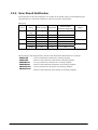
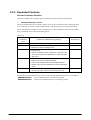
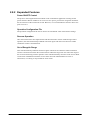
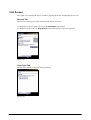
2.2.4 Scan Result Notification
The notification of the read completion of a symbol can be posted using one of the following two
integrated devices. The buzzer sound level can be set up at the Control Panel.
Table 2.29
Device
LED
Buzzer
Vibrator
Setting
Read succeeded
Read failed
Green and
Red
Green
Invalid
Valid
Invalid
Valid
Invalid
ON in green
ON in red
Read terminated
(release the Trigger key)
No
ON in green
No
Sound
No
Vibrates
No
No
No
No
No
No
No
No
No
No
No
No
No
Default
Green and Red
Valid
Valid
The functions of the Imager Library relevant to the Scan Result Notification are as follows.
IMGSetLED
: Sets up notification with LED for scanning complete.
IMGGetLED
: Retrieves the notification with LED for scanning complete.
IMGSetBuzzer
: Sets up notification with buzzer for scanning complete.
IMGGetBuzzer : Retrieves the notification with buzzer for scanning complete.
IMGGetVibrator : Sets up notification with vibrator for scanning complete.
IMGSetVibrator : Retrieves the notification with vibrator for scanning complete.
41
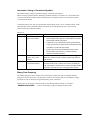
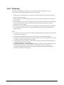
2.2.5 Expanded Features
Decode Customize Function
This function adjusts the scanning speed to facilitate scanning of hard-to-read symbols.
•
Decode Deliberation Levels
The level of deliberation for scanning symbols can be set at five different levels. Setting the level
to “Very Quick” or “Quick” limits symbols which can be decoded, but increases the decoding
speed. Alternatively, setting the level to “Deliberate” or “Very Deliberate” allows many symbols
to be scanned but slows down the decoding speed.
Table 2.30
Decode
Deliberation
Levels
Very Quick
Quick
Normal
Suitable Scan Mode/Bar Code Symbology
−
−
−
−
−
Deliberate
−
−
−
Very Deliberate
−
−
1D bar code with good print quality
1D bar code with poor print quality
PDF417 bar code with 500 digits or less
Package mode
PDF417, MicroPDF, Code49, Codablock F, Composite Code,
Aztec, QR Code, Maxicode, DataMatrix bar codes with 1,000
digits or less.
1D bar codes with very poor print quality
PDF417 bar code with 1,000 to 2,000 digits.
TTLC39, GS1 DataBar Stacked, GS1 DataBar Expanded
Stacked, Aztec, QR Code, DataMatrix bar codes with 80 digits
or less.
PDF417 bar code with 2,000 digits or more
TLC39, Aztec, QR Code bar codes with 80 digits or more
Decode Speed
Very fast
Fast
Normal (default)
Slow
Very slow
The functions of the Imager Library relevant to the “Decode Deliberation Levels” are as follows.
IMGSetDeliberation : Sets up deliberation level for decoding symbol.
IMGGetDeliberation : Retrieves the deliberation level for decoding symbol.
42
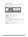
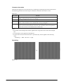
•
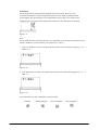
Print Weight Adjust Function
This function improves scanning bar codes comprised with thick or thin bars. The improvement
can be selected in seven grades. In ordinary condition, the setting is not required to change.
However, it is useful to change it if scanning a particular bar code is difficult.
Thin
1
Default
2
3
4
Thick
5
6
7
Figure 2-6
The functions of the Imager Library relevant to the Print Weight are as follows.
IMGSetPrintWeight : Sets up print weight of bar thickness used for decoding symbol.
IMGGetPrintWeight : Retrieves print weight of bar thickness used for decoding symbol.
•
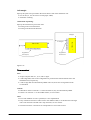
Decode Window Function
This is a function that specifies an area for decoding bar code located in the center of the aimer
emitted by the CMOS Imager. It is useful for decoding a specific bar code symbol only among
plural bar codes printed on same paper sheet. If either Mode 1 or Mode 2 of the parameters is
specified in the Decode Window function, the decoding area is automatically determined to
scan only a bar code located near the center. Setting the User Setting effect in the Decode
Window function allows an area of decoding to be specified with X and Y coordinates.
Table 2.31
Setting Parameters for
Decode Window function
Disable
Mode 1
Mode 2
User Setting
Description
Remarks
Disable the Decode Window function.
Scan a single bar code located in the center area of the aimer.
Scan Composite code located in the center area of the aimer.
Specify decode area with X and Y coordinates.
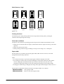
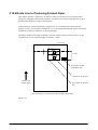
If the Decode Window function is set for scanning a bar code, a bar code or a part of the bar
code that is within the aimer’s area (see Figure 2.9) is scanned, and other bar codes outside of the
area are not scanned. For example, in Figure 2.9, bar code A cannot be scanned because the entire
bar code is outside of the aimer area, but bar code B can be scanned because a part of the bar code
is within the area.
The entire bar code is outside of the area.
A
A part of bar code B is within the area.
Decode area specified by the Decode Window
function which is automatically set up by
designating Mode 1 or Mode2 in the function.
B
Aimer
Figure 2-7
43
Note that the area of the aimer is a reference. It ca be varied by factors such as distance between
the bar code and the terminal or angle of emitting the aimer.
The functions of the Imager Library relevant to the “Decode Window function” are as follows.
IMGSetDecodeWindow : Sets up decode window area.
IMGGetDecodeWindow : Retrieves decode window area.
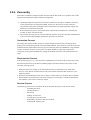
•
Contrast-Reverse Symbols function
This is function that scan special symbols which is printed out white color in black color
background (Reverse printed Symbols).
When you specified Contrast-Reverse Symbols function, such kind of special symbol will be
available to scan.
Table 2.32
Setting
Normal
Contrast-Reverse
Both normal and
Contrast-Reverse
Description
Available to scan normal symbol (printed black color in white color
background.)
Available to scan Contrast-Reverse symbol (printed white color in
black color background.)
Available to scan both normal and Contrast-Reverse symbol.
But scanning performance will be decreased.
Remarks
Default
This is function that scan special symbols which is printed out white color in black color
background (Reverse printed Symbols).
Please take care when you set Contrast-Reverse mode, normal symbol will not be scanned.
About QR code, DataMatrix code and Aztec code is not related with this function setting.
(These type of symbol are available to scan at both mode.)
The functions of the Imager Library relevant to the “Decode Reversed Symbol function” are as
follows.
IMGSetDecodeReverse : Sets up decode mode in reversed colors.
IMGGetDecodeReverse : Retrieves the status of decode mode in reversed colors.
44
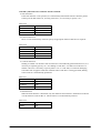
Automatic Linking of Combined Symbols
The CMOS Imager supports automatic linkage of multiple symbologies.
When scanning symbols with the following combined symbols (see Table 2.61), the scanned data
is stored in the internal buffer and all of the data from combined symbols or all scanned symbols
is combined and output.
Combined symbols can only be scanned when the decoding mode is set to “Ordinary Read” mode.
Note that other modes including “Multi-step Read” and “Package Read” may cause incorrect
result of scanning combined symbols.
Table 2.33
Symbology
Code93
Code49
QR Code
Applicable Symbols
Code93 bar codes with a
space at the forefront
Code49 bar codes with
mode 1 (M=1) at the
forefront
QR Code with
combination identifier.
Combination Method
1. When scanning symbols of Code93 symbology whose
forefront begins with a space, the scanned data is stored in the
internal buffer without being output.
2. Furthermore, when continuously scanning symbols starting
with a space, the data is combined in the internal buffer in the
order that it is scanned and is not output.
3. Finally, when scanning symbols other than those whose
forefront begins with a space, it is combined with the
internally stored data and output.
Combination method is the same as for Code93 symbology.
Different to Code93 is that the combined symbols start with M=1
at the forefront.
Indicators displaying the number of symbol divisions and the
sequential number of the symbol are stored in the combined QR
Code. The decoder is therefore able to combine and output all data
in the order of the indicators upon scanning all of the symbols.
Binary Data Scanning
The CMOS Imager is able to output data scanned from symbols not only in standard character
strings but also in binary data. It is therefore possible to scan binary data of encoded data, images
and audio as well as character strings delimited by NULL characters.
The function of the Imager Library relevant to the “Binary Data Scanning” is as follows.
IMGWaitForDecodeRaw : Carries out decoding symbol including its binary data.
45
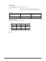
Image Capture Function
This function is used to capture image data and save it as JPEG file. Using the function together
with the JPEG Library, the captured image data is output as image data in either 2-gray scale or
256-gray scale. The captured image data can also be output in low resolution by reducing its size.
The following table shows the reductions and sizes.
Table 2.34
Reduction
Size
Scale
1/1, 1/2, 1/4
1/1 reduction
752 x 480 pixels
1/2 reduction
376 x 240 pixels
1/4 reduction
188 x 120 pixels
Partial extraction is possible.
2- or 256-gray scale
The functions of the Imager Library and JPEG Library relevant to the “Image Capture Function”
are as follows.
IMGGetImage
: Captures still image.
JPGEncodeToFile
: Encodes RGB data or YUV data to output the result as JPEG file.
JPGEncodeToFileEx : Encodes RGB data or YUV data to output the result as JPEG file. It
specifies “with thumbnail” or “without thumbnail”.
46
Signature Index Function
This function scans both symbol and signature at one time and outputs the symbol data and
indexed signature at the same time. The position and size of a signature can be specified in the
user application based on the position of the symbol.
The function automatically corrects the up and down positions of the captured symbol in
correspondence with the up and down positions of the image data even if it has been captured
upside down or diagonally, and then outputs it.
Figure 2-8
•
Supported symbols
Code39
Codabar (NW7)
Code128
PDF417
Aztec
The functions of the Imager Library relevant to the “Signature Index Function” are as follows.
IMGCaptureSign
: Retrieves captured signatures.
IMGWaitForDecode
: Carries out decoding symbol.
IMGWaitForDecodeRaw : Carries out decoding symbol including its binary data.
47
Streaming Display Function
This function sequentially displays an image while continuously operating the CMOS Imager.
With the image capturing function in “ Image Capture Function ”, the streaming display function
can be used to display image preview.
X
Table 2.35
Reduction
Size
1/1 reduction
X
1/1, 1/2, 1/4
188 x 120 pixels
1/2 reduction
1/4 reduction
Partial extraction is possible.
256-gray scale
15 fps or less (see note)
Scale
Frame rate
Note:
The rate may fluctuate depending on the surroundings brightness or the load on the system by
concurrently running program.
The functions of the Imager Library relevant to the “Streaming Display Function” are as follows.
IMGStartStream
: Starts streaming images.
IMGGetStreamData : Retrieves data of streaming images.
IMGStopStream
: Stops streaming images.
Illumination LED and Aimer
The terminal integrates the illumination LED for lighting and the Aimer for focusing a symbol to
scan. Setting the intensity of the illumination LED to zero will turn off.
This setting is useful when the terminal is used outdoor where the illumination LED is not needed,
or when a stamp in red is to be read.
The functions of the Imager Library relevant to the “Illumination LED and Aimer” are as follows.
IMGAimerOn
: Turns on or off the Aimer.
IMGIlluminationOn : Turns on or off the illumination LED.
48
Imager’s APO
This function will shut down the power to the CMOS Imager automatically if it has not been used
for a while.
After activating the APO (Automatic Power OFF) function, the imager’s power can be turned on
again if one of the following functions is invoked. The time period of the APO function can be set
up in the range of 0 to 1,800 seconds. Specifying “0” will disable it.
The power consumption by the imager can be curbed while the APO function is activating.
However, note that it takes about 30 milliseconds to put the power back on.
The functions of the Imager Library relevant to the Imager’s APO are as follows.
IMGSetImagerAPO : Sets up time period for Auto Power OFF.
IMGGetImagerAPO : Retrieves time period for Auto Power Off.
49
2.2.6 Configuration File
The various settings made at “ Imager Setting ” of the Control Panel can be stored in an INI-type
file and resumed. The configuration file storage location and its name are “\FlashDisk\System
Settings\IMGSet.ini”.
X
X
By calling IMGLoadConfigFile function, the content in the configuration file is deployed into
the Imager, or the default values are used to initiate the Imager if there is no such the
configuration file.
The functions of the Imager Library relevant to the Configuration File are as follows.
IMGLoadConfigFile : Sets up the Imager using configuration file.
IMGSaveConfigFile : Retrieves the Imager settings and saves into configuration file.
The setting in the configuration file is divided into two parts, the setting for scanning bar codes
and the other for common operations. See the next three pages.
50
Setting for Scanning Bar Codes
For each symbology, parameters that can define the scanning performances are specified with its
individual symbology name in the section name. See Table 2.64 .
X
X
Table 2.36
Item
[Symbology] Section
Enable
Min
Max
Output Start/Stop Code
Read On Check Char
Read On Check Digit
Output Check Char
Output Check Digit
Read On 2 Check Digit
Full ASCII
Only Carrier Message
Append 2Digit Addon
Append 5Digit Addon
Request Addon
Separate Addon
Output System Number
Expand Version E
Description
Sets up “Enable” or “Disable” for scanning a
symbology.
Specifies the minimum no. of digits for scanning
a symbology.
Specifies the maximum no. of digits for scanning
a symbology.
Sets up “Enable” or “Disable” for output of start
and stop codes.
Sets up “Enable” or “Disable” for scanning a
symbology with check character.
Sets up “Enable” or “Disable” for output of check
character.
Sets up “Enable” or “Disable” for scanning a
symbology with 2-digit check character.
Sets up “Enable” or “Disable” for output of Full
ASCII conversion.
Sets up “Enable” or “Disable” for output of
carrier message only.
Sets up “Enable” or “Disable” for output of
2-digit addon data.
Sets up “Enable” or “Disable” for output of
5-digit addon data.
Sets up “Enable” or “Disable” for scanning a
symbology only with addon data.
Sets up “Enable” or “Disable” for output addon
data separated with space.
Sets up “Enable” or “Disable” for output of
system number.
Sets up “Enable” or “Disable” for output of
12-digit expanded UPCA symbology.
51
Setting
0; disable, 1; enable
0; disable, 1; enable
0; disable, 1; enable
0; disable, 1; enable
0; disable, 1; enable
0; disable, 1; enable
0; disable, 1; enable
0; disable, 1; enable
0; disable, 1; enable
0; disable, 1; enable
0; disable, 1; enable
0; disable, 1; enable
0; disable, 1; enable
List of the Default Settings for Bar Code Symbologies
The below list shows the default settings and parameters for the 1D bar code symbologies.
Table 2.37
[Code39]
Enable=0
Min=2
Max=48
Output Start/Stop Code=0
Read On Check Char=0
Output Check Char=0
Full ASCII=0
Append=0
[EAN13]
Enable=0
Output Check Char=0
Request Addon=0
Separate Addon=0
Append 2Digit Addon=0
Append 5Digit Addon=0
[Interleaved 2of5]
Enable=0
Min=4
Max=80
Read On Check Digit=0
Output Check Digit=0
[MSI]
Enable=0
Min=4
Max=48
Output Check Char=0
[ISBT]
Enable=0
[PDF417]
Enable=0
Min=1
Max=2750
[Composite]
Enable=0
Min=1
Max=2435
UPCE EAN Composite
Enable=0
Continue.
[Codabar(NW7)]
Enable=0
Min=2
Max=60
Output Start/Stop Code=0
Read On Check Char=0
Output Check Char=0
[EAN8]
Enable=0
Output Check Char=0
Request Addon=0
Separate Addon=0
Append 2Digit Addon=0
Append 5Digit Addon=0
[UPCA]
Enable=0
Output Check Digit=0
Request Addon=0
Separate Addon=0
Append 2Digit Addon=0
Append 5Digit Addon=0
Output System Number=1
[UPCE]
Enable=0
Output Check Digit=0
Request Addon=0
Separate Addon=0
Append 2Digit Addon=0
Append 5Digit Addon=0
Output System Number=0
Expand Version E=0
[Code128]
Enable=0
Min=0
Max=80
[Code93]
Enable=0
Min=0
Max=80
[IATA]
Enable=0
Min=4
Max=80
[RSS]
Enable=0
Min=1
Max=80
[MicroPDF]
Enable=0
Min=1
Max=2750
[Maxicode]
Enable=0
Min=1
Max=150
Only Carrier Message=0
52
[Code11]
Enable=0
Min=4
Max=80
Read On 2 Check Digit=1
[Code49]
Enable=0
Min=1
Max=81
[CodaBlock]
Enable=0
Min=0
Max=2048
[DataMatrix]
Enable=0
Min=1
Max=1500
[QR Code]
Enable=0
Min=1
Max=3500
[Aztec]
Enable=0
Min=1
Max=3750
[Code 32]
Enable=0
53
[TLCode39]
Enable=0
Setting for Common Operations
The settings in Table 2.66 are for the common operations not related to bar code symbology.
X
X
Table 2.38
Item
[PrintWeight] Section
PrintWeight
[Intensity] Section
Aimer
Illumination
[Multi-step] Section
ReadMode
ReadTimes
Separator
Description
Default
Specify the calibration value for
thickness of bars.
Specify in the range of
1 to 7.
4
Specify the intensity of the Aimer.
Specify of the intensity of the
Illumination LED.
Specify 0 or 100.
Specify 0 or 100.
100
100
Specify read mode.
0; Ordinary read
1; Multi-step read
2; Package read
Specify in the range of
2 to 10.
Specify character
casted in INT-type.
0
0; Outdoor
1; Indoor (by window)
2; Indoor
3; Warehouse
1
Specify the no. of times to scan in
continuous mode.
Specify the separator (= symbol) in
Package read mode.
[Scan Mode] Section
Scan Mode
Specify scanning mode.
[Decode Deliberation] Section
Decode Deliberation
Set the deliberation level.
[Search Mode] Section
Search Mode
Continue.
Setting
Search mode
54
100; Extremely fast
decoding, but limited
symbologies.
200; Fast decoding with
some limited
symbologies.
400; Normal
800; Slow decoding, but
adequate number of
symbologies covered.
0; Extremely slow
decoding, but many
symbologies covered
-
2
0
400
1
[Auto Power OFF] Section
Auto Power OFF
[Indicator] Section
LED
Buzzer
Vibrator
[Decode Window] Section
Enable
Left
Top
Right
Bottom
[Decode Reverse] Section
Enable
Imager’s APO timer
Specify in the range of
0 to 1800 (in second),
“0” disables APO, “1
to 1800” turns off the
power to the Imager
after the time period
has elapsed.
0
Specify turning on the LED when
scanning is complete.
0; disable, 1; enable in
green, 2; enable
“success” in green and
“failure” in red
0; disable, 1; enable
2
1
0; disable, 1; enable
1
0; disable, 1; mode 1,
2; mode 2, 16; user
define
Specify from 0 to 751
0
Specify from 0 to 479
0
Specify from 0 to 751
751
Specify from 0 to 479
479
0; No reverse
1; Reverse
2; Both
0
Specify turning on the buzzer when
scanning is complete.
Specify turning on the vibrator when
scanning is complete.
Specify decode window mode.
Specify left side coordinate of
decode window.
Specify top side coordinate of
decode window.
Specify right side coordinate of
decode window.
Specify bottom side coordinate of
decode window.
Specify decode reverse mode
55
0
2.2.7 Concurrent Use with Other Device
Table 2.67 shows the concurrent use of decoder, streaming, capturing image of the CMOS Imager
with other devices listed in the below table.
Table 2.39
Other Devices
Camera
USB
Bluetooth
WLAN
Concurrent Use
Impossible.
There may be a possibility, but it is not recommended to use the device concurrently.
Possible.
Possible.
2.2.8 Process of Image
Decoding and Encoding BITMAP/JPEG
The process of image performs encoding image data in BITMAP into JPEG file, and decoding
image data in JPEG file into BITMAP.
Table 2.40
Process
Encoding
Decoding
Setting image quality
and compress rate
(when encoding)
Description
Covert image data in RGB888 (24-bit color) into
JPEG file.
Convert image data in YUV422 into JPEG file.
Convert image data in JPEG into RGB888 (24-bit
color).
Convert image data in JPEG file into YUV422.
0
High compress rate, low image quality
100 Low compress rate, high image quality
Remark
in the range of 0 to
100.
The functions of the JPEG Library relevant to the “Decoding and Encoding BITMAP/JPEG” are
as follows.
: Encodes RGB data or YUV data to output the result as a JPEG file.
JPGEncodeToFile
JPGDecodeFromFile : Decodes a JPEG file to output the result as BMP data.
Embedding Thumbnail into Image File
When saving an image file, the thumbnail can be embedded in the image file (applicable to only
JPEG). Instead of displaying the whole image on the display screen, the thumbnail can be
deployed on the screen to save time to load and decode the file.
The function of the JPEG Library relevant to the “Embedding Thumbnail into Image File” is as
follows.
JPGEncodeToFileEx : Encodes RGB data or YUV data to output the result as a JPEG file. It
adds specified GPS positioning information and specifies “with
thumbnail” or “without thumbnail”.
56
2.3 Digital Camera
This chapter describes about detailed software specifications of the integrated digital camera
(model dependant).
The camera driver integrated in the IT-9000 series handheld terminals is compatible with the
Windows Driver Model (WDM) of Microsoft. Application program runs on the terminal can
utilize the camera functions by controlling DirectShow API.
In this chapter, the properties of the DirectShow that can be set for the IT-9000 series handheld
terminals are mainly explained. For detail of how to use the DirectShow, refer to the document
available in Windows Mobile 6 SDK from Microsoft.
57
2.3.1 Basic Specifications
The terminal (model dependant) offers the following functions via the integrated digital camera
module.
Table 2.41
Item
Recorded image file
format (Still image
capture/consecutive
shooting)
Size of captured still
images
Setting Parameter
JPEG
Portrait
Width Height
1200 1600
960
1280
768
1024
600
800
480
640
240
320
Portrait
Width Height
320
426
240
320
160
213
Mode
UXGA
Quad-VGA
XGA
SVGA
VGA
1/4VGA
Finder (preview) display
Mode
4/9VGA
1/4VGA
1/9VGA
Frame rate
15.0 fps or more
Zoom function
Sequential shooting
function
Shutter sound
Recorded video file
format
Size of captured video
clips
Remarks
- Available JPEG image
quality
Landscape
Width Height
1600 1200
1280 960
1024 768
800
600
640
480
320
240
Landscape
Width Height
426
320
320
240
213
160
- When circumferential
luminance is 500 lx or
more.
Digital Zoom
(XGA capture mode: x1.5)
(SVGA capture mode: x1.5, x2.0)
(VGA capture mode: x1.5, x2.0)
(1/4VGA capture mode: x1.5, x2.0)
Not supported.
Forcible shutter sound by audio
WMV
Portrait
Landscape
Width Height Width Height
240
320
320
240
Mode
1/4VGA
Note:
The orientation (Portrait or Landscape) in Table 2.69 is dependant on the screen orientation of the
terminal. See “ Screen ” settings.
X
X
X
58
X
Preview Display
This is for displaying an image in real time being captured by the camera. The following are
image sizes and frame rates for preview display.
Table 2.42
Item
Screen size in preview display
Frame rate
Parameter
Portrait
Landscape
Mode
Width
Height
Width
Width
4/9VGA
320
426
426
320
1/4VGA
240
320
320
240
1/9VGA
160
213
213
160
Each image size above can be magnified by “x1.0”, “x1.5”, or
“x2.0”.
15 or more frames per second
The functions of the Camera Library relevant to the “Preview Display” are as follows.
: Start preview.
CAMStartPreview
: Stop preview.
CAMStopPreview
59
2.3.2 Capturing Images
Capture Static Image and Save in File
This function captures single static image and then outputs it in JPEG format file.
Table 2.43
Item
Image size to capture
File format
Setting Parameter
Portrait
Width Height
1200
1600
960
1280
768
1024
600
800
480
640
240
320
Mode
UXGA
Quad-VGA
XGA
SVGA
VGA
1/4VGA
JPEG file
Landscape
Width
Width
1600
1200
1280
960
1024
768
800
600
640
480
320
240
After calling the static image capture function, there is a time-lag of approximately 400
milliseconds until when an image is actually captured. The camera driver notifies the operator of
the terminal that the image has been captured with the shutter sound. Focus adjustment can be
performed using the Auto Focus function and the fixed-focus switch (10 levels), thereby enabling
the operator to capture a focused image.
Notes:
• Prior to capturing static images, secure the sufficient memory size (recommended 2Mbytes or
more) remained in storage where the captured static images are stored.
• When temperature of the LED becomes high, for safety, capturing images with flash function
by using the LED and the functions that controls ON/OFF of LED illumination will not be
operable.
60
JPEG File Option
For the use of JEPG as output file, the options listed in the table can be set.
Table 2.44
Parameter
Quality (Compression
rate)
Baseline progressive
Setting
Quality = low (Compression rate =
high)
Quality = middle (Compression rate =
middle)
Quality = high (Compression rate =
low)
Quality = highest (Compression rate =
lowest)
Baseline
Thumbnail function
Progressive output function is not
supported.
Not supported.
Remarks
Default
This is a file format which displays
image from upper line (Default).
The functions of the Camera Library relevant to the “JPEG File Option” are as follows.
CAMGetImageSettings : Retrieve the options of JPEG file.
CAMSetImageSettings : Set up the options of JPEG file.
Movie Capture Function
This is a function for capturing movie and to output the data in movie file.
Table 2.45
Parameter
Image size to capture
Video codec
File extension
Bit rate setting
Audio codec
Frame rate
Setting
Portrait
Mode
Width
Height
1/4VGA
240
320
Microsoft Windows Media Video
wmv
VBR (Variable bit rate)
PCM
6fps to 15fps
61
Landscape
Width
Width
320
240
Digital Zoom
The digital zoom is a function used to cut out a part of image from the high-resolution image. The
following image sizes and magnifications can be used for digital zoom shooting.
Table 2.46 Digital Zoom
Magnification
1/4VGA
VGA
SVGA
XGA
Quad-VGA
UXGA
x 1.5
Yes
Yes
Yes
Yes
No
No
x 2.0
Yes
Yes
Yes
No
No
No
Note:
If shooting is performed in one of the modes marked as “No” in the table, shooting is made
without digital zoom (“x 1.0”) effect.
The functions of the Camera Library relevant to the “Digital Zoom” are as follows.
CAMGetDigitalZoom : Retrieve current digital zoom setting.
CAMSetDigitalZoom : Set up digital zoom setting.
Light Mode Function
The light mode is to allow an image to be captured under a natural brightness according to the
light source in the surrounding area. The following 5 modes can be selected for the light mode.
Table 2.47 Light mode
Auto
Shooting in outdoor in cloudy sky (color temperature = 6500K)
Shooting under fluorescent lamp (color temperature = 5000K)
Shooting under incandescent lamp (color temperature = 2850K)
Shooting under dark place (white balance = auto, shutter speed = slow)
Note:
If a desired image is not captured in the “Auto” mode, specify other light mode according to light
source in the surrounding area. Even if such the optimum light mode is set, other light sources
reflected by wall, etc., may affect the color temperature causing the image to be displayed in
incorrect color tone.
The functions of the Camera Library relevant to the “Light Mode” are as follows.
CAMGetLightMode : Retrieve the current light mode setting.
: Set up light mode option.
CAMSetLightMode
62
Brightness Correction
This is for correcting the brightness. “Brightness” referred to in this explanation is the target value
for automatic exposure. Exposure is determined automatically in accordance with the brightness
of image to capture, but a target value if you wish to set can be set in the range of 0 (dark) to 24
(bright). The default is 12.
The functions of the Camera Library relevant to the “Brightness Correction” are as follows.
: Retrieve the current brightness setting.
CAMGetSensitivity
: Set up brightness setting.
CAMSetSensitivity
Illumination LED
Illumination LED On/Off and its brightness can be set.
Illumination LED should be used to capture image (in close distance only) in dark place using the
digital camera.
Intensity of the Illumination LED can be set in the range of 0 (dark) to 100% (bright). The default
is 80%.
The functions of the Camera Library relevant to the “Illumination LED” are as follows.
CAMIlluminationOn : Turn on and off the Illumination LED.
CAMGetIllumination : Retrieve the current illumination LED’s brightness setting.
CAMSetIllumination : Set up Illumination LED’s brightness.
Flash LED
The Flash LED can be used to capture still images. The Flash LED has two modes, prohibited to
flash and forcible to flash (default). The brightness of the Flash LED can be set in the range of 0
to 100%.
Table 2.48
Parameter
Flashing the LED
Intensity switch over
Setting
Prohibited to flash (default), Forcible to flash
0% (dark) to 100% (brightness), default is 80%
The functions of the Camera Library relevant to the “Flash LED” are as follows.
: Retrieve the current Flash LED setting.
CAMGetFlash
: Turn on and off the Flash LED.
CAMSetFlash
CAMGetIllumination : Retrieve the current brightness of the Illumination LED.
: Set up brightness of the Illumination LED.
CAMSetIllumination
63
Compulsory Shutter Sound
The shutter sound is generated by the audio during shooting photos. To prevent video voyeurism,
whatever the case, it is forced to sound including when the audio is set to mute and when a set of
earphones is being used.
Flickerless
The CMOS Camera in built-in IT-9000 detects flicker automatically and minimizes the affection
by it.
Focus Adjustment
The CMOS digital camera is equipped with a focus adjustment function to enable the operator to
capture focused images. This adjustment comes in the form of a fixed-focus switch and an
autofocus feature. The fixed-focus switch enables the application program to switch the focus to
suit the distance to the object being captured.
The autofocus feature automatically adjusts the focus to suit the distance of the object being
captured. Executing the autofocus function in preview mode automatically adjusts the lens
position to focus the camera. The autofocus adjusts the preview screen s fixed area (focus area) so
that it comes into focus. When the focus area and the focus frame display functions are enabled, a
frame known as the focus frame appears on the preview screen. The focus frame appears green
when the autofocus has been successful. When the autofocus function is not selected or when it is
unsuccessful, the focus frame turns to red. When capturing a still image upon successful autofocus,
the focus frame returns to red.
Table 2.49
Parameter
Fixed-focus switch
Autofocus
Focus frame display
Setting
Range of 1 (close range) to 10 (long range)
No setting required
Disabled (default) or Enabled
The functions of the Camera Library relevant to the “Focus Adjustment” are as follows.
: Retrieves the position set with CAMSetFocus function.
CAMGetFocus
:
Sets up the focus position.
CAMSetFocus
: Retrieves the current focus position.
CAMGetFocusStatus
: Adjusts focus in automatic focus
CAMAutoFocus
64
Flipping Image
In the IT-9000, the direction of flipping image on the screen is determined in accordance with
OS’s screen flip setting. For the specifications of flipping screen image, refer to “Camera
Rotation” in MSDN library.
Table 2.50
Item
Flipping
image
Image
Preview display
−
−
−
−
Captured image
−
−
−
−
Setting
(Flip image in clockwise)
No flip (default)
90 degree (OS. When specifying image to flip 90 degree
in clockwise.)
270 degree (OS. When specifying image to flip 90
degree in counterclockwise.)
(Flip image in clockwise)
No flip (default)
90 degree (OS When specifying image to flip 90 degree
in clockwise.)
270 degree (OS When specifying image to flip 90 degree
in counterclockwise.)
Adjusting Frame Rate
Frame rate which is output to preview display by the integrated camera module is adjusted
automatically in accordance with the surrounding brightness, not exceeding the maximum frame
rate. The camera module has the capability of setting the maximum frame rate. It is to set the
maximum frame rate in 4 grades output by the camera module in preview display. In capturing
movie, the maximum frame rate requires the software resource used for encoding. The more you
set higher frame rate, the more it takes time to encode and the program memory is needed.
Table 2.51
Parameter
Maximum frame
setting
Setting
Max. frame rate = low
Max. frame rate = ordinary
Max. frame rate = high
Max. frame rate = highest
65
−
−
−
−
−
−
−
−
−
−
Remarks
When capturing movie
Encode time = short
Program memory required = small
When capturing movie
Encode time = middle
Program memory required = ordinary
When capturing movie
Encode time = long
Program memory required = large
Not allowed to set for capturing movie.
Adjusting Movie File
The integrated camera module has the capability of setting movie quality (delicacy, smoothness,
beauty of the movie screen when playing back movie) and recording sound in capturing movie. If
you set the screen quality higher, captured movie can be in a good quality, but it makes the file
size be swelled. It can also set sound in recording movie. If you play with some of the buttons
while you are capturing movie, it may record sound. Before starting movie, be sure to secure
sufficient free memory for both storage and program (10MB or more for storage memory or
35MB or more for program memory with the assumption that high screen quality, frame rate at
high, with recording sound and time period of 30 second to capture movie are set.)
Table 2.52
Item
Screen quality(Compression
rate)
Movie file format
With sound or without
Setting
Quality = low
(Compression rate = high)
Quality = middle
(Compression rate = middle)
Quality = high
(Compression rate = low)
Quality = highest
(Compression rate = lowest)
WMV
With sound
Without sound
Remarks
Default
Encoder : Windows Media Video 9
FourCC: WMV3 (Default)
Default
Control on Power/CPU Clock
While the camera is in operation (preview display, capturing images, capturing movie), set the
CPU clock to its highest for the speed of capturing movie until preview display ends.
To save power consumption, always turn off the power to the camera module and ASIC for the
camera module while the camera is not in operation. Turn on the power only when the camera is
in operation and turn off it again as soon as the use of the camera is ended.
Control on Exclusive Operations
The operations in the table are exclusive processes with the camera. The integrated CMOS Imager
(model dependant) is controlled to avoid the concurrent use with the camera. This is that both
devices use the same hardware resource in the terminal. If both devices are operated at same time,
either one of the devices initiated first has the priority over the other. For example, if you attempt
to operate “preview display” while the CMOS Imager is being opened, the camera driver returns
an error.
Table 2.53
Device
Camera
CMOS Imager
Excluded Operations
Preview display, capturing still image, capturing movie.
Opening CMOS Imager.
66
2.4 Near Field Communication (NFC)
2.4.1 Basic Specifications
The following types of smart card can be accessed for reading and writing by the Near Field
Communication (hereafter referred to it as NFC) integrated in the terminal.
•
•
•
•
ISO/IEC14443 Type A (MIFARE Standard; Ultralight) See note 1.
ISO/IEC14443 Type B
FeliCa;FeliCa Lite See note 2.
ISO15693(Tag-It HF-I Plus, ICODE SLI, ICODE SLI-L, ICODE SLI-S, my-d V 10 Plain,
my-d Light, Tag-it HF-I Plus, Tag-it HF-I Pro, Tag-it HF-I Standard) See note 3.
Notes
- Memory configuration and command specifications of each card are different. Refer to
specifications of the respective cards.
Notes
1.
The NFC does not support MIFARE DESFire, ProX, SmartX, and Plus cards. The security
feature specifically implemented in these cards is not supported by the NFC.
2.
The FeliCa security area can be accessed by using a FeliCa SAM card “RC-S251”.
RC-S251 can be accessed from the SAM library or the NFCFelica library.
3.
About Tag-it series, Lock AFI / LockDSFID command is not supported by NFC controller
specification. And when you use Write Single Block / Lock Block / Write AFI / Write
DSFID command, you need to execute re-try operation of command in user application.
67
2.4.2 Communication Functions
Reading and writing data with a smart card is performed by the way of contactless communication
between the integrated NFC module in the terminal and that smart card. Smart card is
preprogrammed by the manufacturer to perform certain operations in response to prescribed
commands. When a command is correctly transmitted by the terminal via the NFC to smart card,
the smart card responds to the received command by performing a corresponding operation. Once
the operation is complete, the smart card then transmits response indicating the result of the
operation.
An explanation of the functions relating to this communication process is provided below.
Card Polling Function
This function carries out the following performances.
•
Searches smart cards within the communication range
•
Detects smart card
•
Activates smart card
•
Retrieves smart card response information
The card polling function terminates searching smart cards either when it detects a smart card, the
preset timeout elapses, the assigned callback function returns 'FALSE', or the 'stop polling'
function is carried out.
Once the smart card has been successfully activated, the NFC module continually transmits radio
waves in order to supply power to the smart card. This radio wave transmission terminates
automatically when the 'radio off' function is carried out or when a certain preset time elapses
without any communication between the NFC module and the smart card. It is possible to enable
or disable the automatic stop (auto stop) setting and to change the time until the auto stop occurs
(i.e. the timeout). Under the default settings, the auto stop is set effect and the timeout is set to
1,000 milliseconds.
About IC card search method
There are following search methods.
Search method
Normal mode
Detail
One piece IC card will be started. Search operation
will be terminated by the following condition.
. Find one IC card
. Passed timeout period
. Specified call back function return FALSE
. Execute polling stop function
68
Usage
This is simple method for
communicate with one
IC card, normally this
method should be used.
Multi Step
mode
While specified call back function return TRUE, start
IC card continuously. There is no case to start again
IC card which started before. Control will be
returned to application at each IC card start timing.
Application will start IC card as maximum 100
pieces according to execute this function
continuously. Search operation will be terminated by
the following condition.
. Find one IC card
. Passed timeout period
. Specified call back function return FALSE
. Execute polling stop function
If you do not scan again
before scanned and want
to scan IC card
continuously like Goods
stock taking, in such case
Multi Step mode should
be used.
Started card's Uid will be recorded in driver history
at each IC card started. Double starting will be
prevent by compared this history and started IC card.
This history record will be clear by started specified
IC card, passed timeout period, call back function
return FALSE, execute polling stop function.
Multi Step 2
Basically execute same as Multi Step operation, but
Should be used same as
mode
operation which found IC card started before will be
Multi Step operation
different. Case of Multi Step operation, when IC card
started before is found, search operation will be
continued without notify upper application, Case of
Multi step 2 operation, when IC card started before is
found, search operation will be continued with notify
upper application.
Package mode This is package function which start same type
Should be used package
several IC cards at the same time. 4 pieces IC cards
mode for scan specified
as maximum can be started as package mode.
several IC cards at the
Search operation will be terminated by the following same time.
condition. (*1, *2, *4)
. Find specified number IC card
. Passed timeout period
. Specified call back function return FALSE
. Execute polling stop function
- *1 Type B is not supported in Package mode.
- *2 Cards which can scan at the same time in package mode is same card type only. Therefore it
is impossible to scan different type cards at the same time. Ex. TypeA and Felica card can not
scan at the same time.
- *3 When you want to start Multi Step operation to Mifare Standard 4 Byte UID type card and if
there is same UID card in some target cards inside, first card is OK for scanning but second card
can not scan.
*4 About maximum number of package mode, Type A is 4 pieces, FeliCa and ISO15693 is 2
pieces.
69
Power saving control at card polling
It is possible to save power consumption by search IC card with adjust to long as radio wave
sending period.
But sending period will be longer than before, then IC card detect response will be down.
Please try to use this method for long time continuously IC card waiting case.
Data Communication Functions
Data communication becomes possible once the smart card has been activated by the card polling
function. Communication ends once the NFC module has received the response information from
the smart card in response to a transmitted command or when the timeout elapses.
When the communication is successful, the smart card remains in the activated mode, thus
enabling consecutive transmission of other data.
Table 2.54
Function
Card polling
Data
communicati
on
Description
Searches smart cards within
communication range and,
upon detection, activates
smart card and retrieves its
response information.
Data communication can
be performed with
successfully activated smart
card.
−
−
−
−
−
−
Termination Criteria
Smart card is successfully activated
and card information is retrieved.
Timeout elapses.
Assigned callback function returns
'FALSE'.
'Stop polling' function is carried out.
Smart card response information has
been received.
Timeout elapses.
Timeout
In the range of
100 to 60,000
milliseconds
or
no timeout.
60 milliseconds
(see note)
Note:
A timeout occurs if the wait time, starting when the NFC module transmits a command to smart
card until when the NFC receives a response from the smart card, elapses 60 milliseconds.
70
Below is an example of data communication between the NFC module and smart card.
Figure 2-9
Note:
The NFC module consumes very little power while it is turned on. In addition, turning on the
module takes time so if you would like to start communicating with a smart card very quickly,
turn on the module at same time when activating the application. To start communication with a
smart card, start it by performing card polling. After the application is complete, be sure to close
the NFC module.
71
2.4.3 Expanded Features
Radio Wave Auto Stop Timing Notification
After successfully activating a smart card with the card polling function, the radio wave
transmission will stop automatically if a certain time period elapses without any data
communication between the NFC module and the smart card. If this happens, it is possible to send
a notification, via either a window message or an event, of the timing when the radio wave
transmission stopped. This notification function can be set effect or disabled, and is set disabled
by default.
2.4.4 Power Control
Power-off When Not in Use
In order to save power, no power is supplied to the NFC module and the ASIC for controlling the
NFC module when the devices are not open. The devices are turned on with the respective open
functions and turned off with the respective close functions.
Control on Power When Terminal is Off
The NFC control software switches on/off of the module when the terminal is turned off.
Furthermore, when the terminal power is switched on again, the NFC control software carries out
relevant process corresponding to what the module was in when the terminal was turned off. The
respective operations which occur when the terminal power is turned on or off are shown in the
table below.
Table 2.55
Mode
Card polling in process
−
−
−
−
−
−
Terminal power OFF
Card polling suspended
Power off on module
Data communication suspended
Power off on module
Power off on module
No processing
−
−
−
Terminal power ON
Power on on module
Card polling resumes (note 1)
Power on on module (note 2)
Data communication in
process
Open mode
− Power on on module
Closed mode
− No processing
Notes:
1.
When card polling resumes after the power is turned back on, the timeout restarts from
where it ended in the card polling before the power on the terminal is turned off. In addition,
counting time on card polling is suspended while the terminal power is off.
2.
In case the module power is turned off during data communication with smart card and
operation is suspended, the power supply to the smart card is also interrupted so the mode
on the card is reset. Carry out card polling to restart communication.
72
2.5 Secure Application Module (SAM)
This chapter describes about detailed specifications of the SAM.
2.5.1 Basic Specifications
Access functions are supported for SAM cards inserted in the SAM card slot. Communication can
be performed with SAM cards compliant with ISO7816.
2.5.2 Power Control
SAM card controller power control
When a SAM device is opened, power is supplied to the SAM card controller and the ASIC that
controls the controller. When a SAM device is closed, power to the SAM card controller and the
ASIC that controls the controller is cut off.
The following SAM library functions relate to this function.
SAMOpen
SAMClose
: Turns on power to the SAM card controller
: Turns off power to the SAM card controller
SAM card power control
The power supply for the SAM card can be controlled to switch on and off by executing a SAM
library function while a SAM device is open. Up to three card slots are equipped (*1) and the
power supply to each card slot can be controlled to switch on and off.
*1 The number of card slots varies between models.
The following SAM library functions relate to this function.
SAMPowerUpCard
: Turns on power to the SAM card in the specified slot
SAMPowerDownCard : Turns off power to the SAM card in the specified slot
2.5.3 Communication Functions
Command Send/Receive Functions
APDU (Application Protocol Data Unit *1) format commands can be sent to a SAM card that is
switched on. Information from the SAM card in response to such commands can be acquired.
*1 Refer to the ISO7816-3 standard for details of the APDU format.
The following SAM library functions relate to this function.
SAMExchangeData
: Sends APDU-format commands to the SAM card in the
specified slot, and receives responses
73
The following is an example of command send/receive operations between the application and the
SAM card.
Application
SAM library
SAM card
SAMOpen
SAMOpen return
SAM card controller
power on
SAMPowerUpCard
Power on
SAM card power on
Response data
SAMPowerUpCard return
SAMExchangeData
Send APDU command
SAMExchangeData return
Receive APDU
response
Process APDU
command
SAMPowerDownCard
Power off
SAM card power off
SAMPowerDownCard return
SAMClose
SAMClose return
SAM card controller
power off
Communication with multiple slots
Power on control and commands to SAM cards in other slots can be sent and received while
power to the SAM card in any other slot is maintained. In case of switching access between SAM
cards in the slots, the accessed slot is switched without cutting off the power to the slot that was
accessed immediately before, so that switching access back to the previous slot is immediate.
74
2.5.4 Processing During Suspend and Resume
The SAM control software switches the SAM card controller and the SAM card off when the
handheld terminal is turned off. The actions stated in the table are performed when the terminal
resumes.
Table 2-5-3
Mode
Open mode
Card power is on
Closed mode
When terminal is suspended
SAM card controller power off
SAM card power off
SAM card controller power off
SAM card power off
No process
When terminal resumes
SAM card controller power on
SAM card power off
SAM card controller power on
SAM card power on (*1)
No process
*1 When the terminal is suspended by auto power off etc., the content set on the SAM card is
initialized. To restore previous status, it is necessary to make the previous settings again after
resuming.
75
2.6 USB
This chapter describes about detailed specifications of the USB.
2.6.1 Basic Specifications
Switching USB
•
•
•
•
Switching between USB Client and USB Host is carried out by following electric signals.
- Signal occurred by the USB cable (for USB Client/Host)
- Signal occurred by the cradle
This cannot be performed in application.
Don’t switch during USB communicating and while USB device is connected and the terminal
is recognizing the USB device.
It is possible to check the current status of USB Client/Host by USB Connection applet.
You can select preferential connection (USB cable or cradle) by USB Connection applet.
Preferential connection works when USB cable is connected to the terminal and terminal is on
the cradle. (See 3.26 USB Connection for its detail.)
Figure 2.10
Table 2.56 In case connection by USB cable is set as preferential USB connection
Terminal
Cradle
Any USB device is not connected
Any USB device is not
connected
No USB connection
Connection by cradle
(USB Client) is effective
USB device is connected
to USB Client connector
Connection by USB cable
(USB Client) is effective
Connection by USB cable
(USB Client) is effective
USB device is connected
to USB Host connector
Connection by USB cable
(USB Host) is effective
Connection by USB cable
(USB Host) is effective
USB device is connected to USB
Client connector and selector
switch is set to "B" position
USB device is connected to USB
Host connector and selector
switch is set to "A" position
Connection by cradle
(USB Host) is effective
Connection by USB cable
(USB Client) is effective
Connection by USB cable
(USB Host) is effective
Notes:
• If USB cable is connected to the terminal when connection by cradle has been established,
connection by cradle will be disconnected and connection by USB cable will be established.
76
Table 2.57 In case connection by cradle is set as preferential USB connection
Terminal
Cradle
Any USB device is not connected
USB device is connected to USB
Client connector and selector
switch is set to "B" position
USB device is connected to USB
Host connector and selector
switch is set to "A" position
Any USB device is not
connected
No USB connection
Connection by cradle
(USB Client) is effective
USB device is connected
to USB Client connector
Connection by USB cable
(USB Client) is effective
Connection by cradle
(USB Client) is effective
USB device is connected to
USB Host connector
Connection by USB cable
(USB Host) is effective
Connection by cradle
(USB Client) is effective
Connection by cradle
(USB Host) is effective
Connection by cradle
(USB Host) is effective
Connection by cradle
(USB Host) is effective
Notes:
• If terminal is put on the cradle when connection by USB cable has been established,
connection by USB cable will be disconnected and connection by cradle will be established.
USB Client (USB Function)
•
•
•
Supports the USB 1.1 full speed.
Communication with PC can be established via ActiveSync/Windows Mobile Device Center.
Communication with PC can be established via FLCE/LMWIN (this case,
ActiveSync/Windows Mobile Device Center must be disabled.)
USB Host
•
•
•
•
•
Supports the USB 1.1 full speed.
Supports USB-MODEM, USB-LAN, and USB-Storage.
USB device is disconnected when the terminal is suspended.
Does not support WakeOn Ring and WakeOn LAN.
Does not support communication via USB HUB.
USB-MODEM
•
•
•
Supports the USB Communication Class (CDC: ACM).
Communication with modem via virtual COM port can be established.
Dial up via USB modem can be possible by selecting USB modem at the setting of connection
under Windows Mobile.
USB-LAN
•
•
Supports the Ethernet Cradle.
Can be connected to network via the TCP/IP protocol using the TCP/IP Wrapper Driver.
USB-Storage
•
Supports USB-Storage.
77
2.6.2 COM Port
COM ports used with the USB are as follows.
Table 2.58
USB Function
USB-MODEM
COM2
COM5
2.6.3 Product ID
USB product ID is as follows.
Table 2.59
USB Product ID
0x00CE
2.6.4 Vendor ID
USB vendor ID is as follows.
Table 2.60
USB Vendor ID
0x045E
78
2.7 Bluetooth
This chapter describes about detailed specifications of the Bluetooth.
2.7.1 Basic Specifications
Version
Bluetooth® Version 2.0 + EDR
Master
The master establishes a connection with Bluetooth equipment in slave mode waiting for
connection with the master.
Client (Slave)
The client (slave) becomes in waiting mode for communication initiated by the master.
Security/Encryption
This performs security (PassKey exchange) and encryption as laid down in the Bluetooth
standard.
AFH
This automatically limits and controls radio wave frequency band to be employed in Bluetooth
communication.
Fast Connection
This is to convert radio frequency for Bluetooth communication into transmission pattern which
allows connection establishment quickly.
EDR (Enhanced Date Rate)
If the communication partner supports also EDR, the EDR is set as radio wave type automatically
by negotiation with the partner device. There is no setting required for the EDR mode.
Communication seed via the EDR between the two terminals is approximately 500 Kbps
maximum.
79
2.7.2 Communication Profiles
The Bluetooth profiles described in the table are supported.
Table 2.61
Function
GAP
(General Accessible Profile)
SDP
(Service Discovery Profile)
Serial Profile
(Client)
Serial Profile
(Server)
DUN
(Dial-Up Network)
OBEX Object Push Profile
HeadSet Profile
Purpose
Used in the substructure segment of Bluetooth communications
such as device discovery, link establishment and security.
Used to search for currently usable services provided by the
partner Bluetooth equipment.
In Bluetooth serial communication, this is used for connection
to other Bluetooth equipment.
In Bluetooth serial communication, this is used for acceptance
of connection request from other Bluetooth equipment.
This is used in dial up communication via Bluetooth mobile
phone.
(Windows Mobile Classic Only)
This is used as easy file send and receive.
This is used in telephone (voice communication.) via Bluetooth Headset.
(Windows Mobile Professional Only)
Bluetooth communication applications and communication methods as well as profile
relationships are as follows.
Table 2.62
Partner Bluetooth Equipment
Bluetooth mobile phone, Bluetooth modem,
etc.
Bluetooth printer
PC for Bluetooth + ActiveSync
80
Communication
Application
Dial up
DUN
Printing to printer
Connection with host PC
Serial Profile
Serial Profile
Profile
2.7.3 Security
This feature supports security functions laid down in the Bluetooth standard. The Bluetooth
security is divided into authentication and encryption.
These are realized by the use of PassKey (otherwise known as PIN code). PassKey is a shared
(common) authentication key used when forming a connection and trust relationship (bonding)
with Bluetooth equipment. A maximum of 16 characters (in ASCII code) can be used, but there
may be limitations on the no. of digits and usable characters due to the specifications of partner
Bluetooth equipment. Also PassKey input must be done within 30 seconds from a time when
PassKey input request is generated. Note that PassKey input is not required once “device trust”
has been established with Bluetooth equipment in previous connection. However, the partner
Bluetooth equipment must have also the trust relationship in memory.
Encryption is carried out using a link key generated after PassKey exchange and a cipher key
generated from a 128-bit random number. Here, the partner Bluetooth equipment also must
support the encryption. PassKey exchange is required for Bluetooth connection when encryption
is set enabled.
2.7.4 COM Port
The following is the COM ports used with the Bluetooth.
Table 2.63
Serial Profile (Client)
Serial Profile (Server)
COM6 / COM7
Case of using CASIO Bluetooth library
Table 2.64
Serial Profile (Client)
Serial Profile (Server)
COM6
COM7
Simultaneous Use of Multiple Bluetooth COM Ports
Multiple Bluetooth COM ports by Serial profile can be opened simultaneously to use.
At this time, you should specify COM port at each Bluetooth devices.
About procedure of connection using multiple Bluetooth devices in Microsoft Stack, please refer
the following URL.
http://msdn.microsoft.com/en-us/library/aa916877.aspx
81
2.7.5 Simultaneous Use with WLAN
Since Bluetooth employs the same frequency range (2.4GHz ISM band), Bluetooth cannot be
operated concurrently with WLAN. However, it is possible to make mutual interference less by
following the instruction without turning off the power of either device.
•
If the partner Bluetooth device supports AFH (Adaptive Frequency Hopping)
AFH function automatically avoids the channels such as WLAN equipments are in use. But
in some case, Bluetooth communication affects other communications such as WLAN.
•
If the partner Bluetooth does not support AFH (exclusive use of Bluetooth and WLAN)
- Confirm that WLAN communication has been finished before performing Bluetooth
connection. If Bluetooth connection is performed while WLAN is used, radio wave from
Bluetooth will significantly affect WLAN communication. Communication error by
interference by Bluetooth radio wave can be reduced if Bluetooth communication is started
after receiving data via WLAN.
- Confirm that Bluetooth communication has been finished and Bluetooth connection is
terminated before WLAN communication starts.
- If another terminal fails to perform communication via WLAN/Bluetooth, keep the terminal
away from this terminal as far as possible and start to operate Bluetooth again.
- For WLAN communication to carry out, operate the terminal as close to Access-Point (for
WLAN) as possible. As it is assumed that Bluetooth devices are operated near by the user,
affect by interference mainly occurs on WLAN device. If the terminal distances from the
Access-Point, affect by interference generated by Bluetooth device will increase causing
LAN communication to fail. If this happens, place the terminal as near to the Access-Point
as possible and operate WLAN communication again.
Note:
Even if either one of the methods described above has been determined to be effect, thorough
check and assessment on the site and for system designs must be carried out prior to
simultaneously operating Bluetooth and WLAN communications.
82
2.7.6 Communication Range
The communication range for Bluetooth communication between two Bluetooth devices should be
3 meters or less. If there is an obstacle exists on the path that blocks radio wave, the actual range
may become shorter. Secure free path for maximum range.
83
2.8 WLAN
The IEEE802.11 b/g WLAN is operable with integrated WLAN module (model dependant). The
IEEE802.11 b/g standard utilizes 2.4 GHz ISM (“Industry Science Medical”) frequency band,
which is used for short range wireless communication.
U
U
U
U
U
U
Device Name
On the terminal, the device name used to capture data, with DeviceIoControl function, about the
WLAN driver is “SDIO86861”.
2.8.1 Basic Features
Roaming
This function automatically switches Access-Point in environment where two or more
Access-Points with identical SSID code exist.
Power Saving
This saves the power by automatically turning off the power to the integrated WLAN module in
the terminal when communicating does not take place.
AdHoc
This operation mode provides a direct communication between wireless equipments without the
use of Access-Point. Note, however, that the AdHoc mode is not recommended to operate because
connection problem may occur.
WEP
This is an encryption that uses RC4 method for safe communication. It supports 40-bit (64-bit)
and 104-bit (128-bit).
TKIP
TKIP supports against the weakness of WEP encryption.
AES
Advanced Encryption Standard (AES) is available for encryption method.
Enhanced Encryption
In order to address WEP vulnerabilities, the driver supports WEP key transmission, the new
encryption method TKIP and the AES-developed TKIP. However, AES typically requires
encoding and decoding hardware. The terminal supports AES and is compatible with WPA2.
802.1x Security
This can strengthen authentication and establish a safe and reliable communication via WLAN. In
general, this interlinks with TKIP and AES. It supports PEAP-EAP-MS-CHAP-V2 and EAP-TLS.
84
2.8.2 Expanded Features
Power ON/OFF Control
The power to the integrated WLAN module can be controlled in application. Turning off the
power when the WLAN module is not in use can save power, prevent line congestion and allow
the on-board use of the terminal in aircraft. However, it is recommended to consult a cabin crew
prior to use of it.
Operation Configuration File
The operation configuration file can be used to set each default value of the WLAN settings.
Resume Operation
After the terminal went into suspend mode and then returned in resume mode during wireless
operation, this will automatically establish connection again with the Access-Point to enable
continuous wireless communication.
Out of Range/In Range
This will automatically establish connection again with the Access-Point to enable continuous
wireless communication when the terminal returns within the range from out side of the range of
the Access-Point during wireless operation. This will automatically reconnect to the Access-Point
if connection establishment with the Access-Point cannot be maintained due to noise or
interference, or roaming is not possible for some reason.
85
2.8.3 Roaming
This feature automatically switches one Access-Point to another in where two or more
Access-Points with the identical SSID code exist are installed.
1. Searches for Access-Points that can communicate with the terminal, and lists up radio wave
status of each Access-Point.
2. Compares radio wave status of the currently connected Access-Point with those for the listed
Access-Points.
3. If the comparison proves that one of the listed Access-Points has a better radio wave status than
the one currently being connected with the terminal, the terminal will make a request of
roaming to that Access-Point.
4. If roaming permission comes from the Access-Point to the terminal, the roaming will complete.
Note that if the roaming fails, the connection establishment will be disconnected and then
connected again.
Notes:
• In some cases, the Access-Point may request the terminal for forcible roaming or reconnection
with another Access-Point.
• If connection establishment of the Access-Point being connected with the terminal is
terminated due to some reasons such as turning off the power on it, the terminal may be forced
to make a connection with another Access-Point.
• If it takes time for Access-Point to correspond for roaming request made by the terminal, the
reconnection process may be initiated.
• If DeAuthentication or DisAssociation message issued by the Access-Point that is being
connected with the terminal is received by the terminal after roaming completed, the
connection establishment between the Access-Point and the terminal may be interrupted
temporarily and then connected again.
86
2.8.4 Zeroconfig
This feature coordinates with the module firmware and the WLAN driver to perform some of the
WLAN link management and the Network management.
• If multiple SSIDs are registered as prioritized connections, attempt to establish connection
will be performed to each registered SSID. In this case, the interval of time period for
reconnecting will become prolonged. If the reconnection time ranks important, register one
SSID only as prioritized connection.
• Reconnection loop process will initiate when a disconnection notification is issued by the
module, or when Association fails.
• The reconnection loop process will end when the terminal succeeds connection establishment
with one of the multiple SSIDs registered as prioritized connections.
Connection Process
Zeroconfig will instruct the WLAN driver and the WLAN module to make connection when
finding an Access-Point registered in the prioritized SSID list. Each firmware of the driver and the
module both instructed initiates necessary process following the rule of IEEE802.11 b/g standard
to make connection with the Access-Point. If multiple SSIDs are registered as prioritized
connections in the prioritized SSID list, attempt to establish connection with each SSID will be
made.
Disconnection Process
In the following cases 1 to 3, the connection establishment via WLAN with Access-Point will be
disconnected. Firmware in the WLAN module judges on the disconnection and carries out the
necessary roaming process.
1. When the radio wave quality in air deteriorates because of interference from other radio
devices, noise, WLAN communication in the same channel with other WLAN device, or in
adjacent channel.
2. When the terminal distances from Access-Point, or when radio wave weakens due to obstacle.
3. When another Access-Point that can allow roaming to avoid the poor conditions described in
the situations 1 and 2 above cannot be sought.
Resume Process
The following processes are carried out when the terminal takes place in the resume mode.
Unloading the driver
Loading the driver
Initializing
Seeking Access-Point
Creating the Access-Point list
Establishing connection with Access-Point
Changing the Tasktray icon
87
2.8.5 Channels
The no. of WLAN channels set by default at the factory is “1CH-13CH” (13 channels) compatible
with the ETSI standard (EU radio standard).
2.8.6 WLAN Setting with Configuration File
The configuration file can be used to set the default values for the WLAN settings. By loading the
configuration file into the terminal, setting to configure the WLAN operations can be easy.
•
•
The configuration file is “\Documents and Settings\System Settings\WLANCFG.ini”.
If no configuration file is available, WLAN operation is initiated with the default settings.
Timing to Load the File
The timing for loading the configuration file is when a reset or a full reset is performed on the
terminal. However, if any one of the following cases occurs, setting with the default values in the
configuration file will not take place.
• The file itself does not exist.
• The format is wrong.
• “Disable configuration file” has been set in the WLANCFG parameter.
Creating Configuration File
The configuration file can be created and edited with WLAN Settings tool at the Control Panel.
Using a general editor, a configuration file can be also created.
WEP key must be created in advance with an encrypted character string using the WLAN
Setting tool and then copy and paste it to the configuration file. WLAN settings made with
Microsoft’s WLAN setting will be ignored in the configuration file.
88
File Format
The file format of configuration file is INI format which follows restrictions described below.
•
•
•
•
•
•
The maximum size of the configuration file is 60 Kbytes.
A line starting with “;” is regarded as comment. It does not regard as comment if located in
mid-line.
The separator for KEY and VALUE is “=”. Space and tab, etc., also are included in either
KEY or VALUE. If a space is inserted after “=”, for example, in “SSID= tunami”, the SSID
value includes the space (“ ”)+tunami.
At the end of line, CR/LF or CR or LF must be attached.
The maximum length of line is 256 bytes.
Section name, KEY and VALUE are not case-sensitive.
WLAN Section
General setting for the WLAN settings is made in this section.
Table 2.65
KEY
WLANPOWER
POWERSAVE
WLANCFG
RoamingRSSILevel
RoamingAvailableTime
RoamingRSSISpan
BandConfig
MAX_SCAN_TIME
SCAN_CHANNELS
WLAN_CFG_TOOL
VALUE
Set turning the power to the integrated WLAN module on or off.
1: Power ON
0: Power OFF
Set the power save mode effect selecting either value.
1: Enable the power save.
0: Disable the power save.
Enable or disable the configuration file.
1: Enable the file.
0: Disable the file.
Set roaming threshold value in dBm.
Set time period in second to start roaming again.
Set difference of roaming radio wave intensity in dBm.
Set communication speed selecting either value.
0: IEEE802.11b
1: IEEE802.11 b/g
Set time period per channel in millisecond to seek Access-Point.
Set channels in successive hexadecimal codes to use.
Example
123456789ABCD : Choose all channels.
16B
: Choose 1Ch, 6Ch, 11Ch.
Select a tool, either NETUI or WLANCONFIG, that appears when the
WLAN icon is selected.
89
STATIC Section
This section specifies parameters necessary for the integrated WLAN module to establish
connection with Access-Point.
Table 2.66
KEY
SSID
ADHOC
WEP
KEYINDEX
KEYDATA
SECURITY
AUTH
WEP_OPEN_KEYINDEX
WEP_OPEN_KEY
WPA_PEAP_USER
WPA_PEAP_PASS
WPA_PEAP_DOMAIN
WPA_PEAP_VALIDATESERVER
WPA_TLS_DOMAIN
WPA_TLS_VALIDATESERVER
WPA_TLS_CERTIFICATE
WPA_PSK_KEY
WPA2_PEAP_USER
WPA2_PEAP_PASS
Continue.
VALUE
Set SSID.
Set Infrastructure or AdHoc mode selecting either value.
1: Infrastructure
0: AdHoc
Set WEP to be included or not.
1: Without WEP
0: With WEP
Set WEP key INDEX in the range of 0 to 3.
Using the WLAN Setting tool, set encrypted WEP key
data selecting either value.
20 bytes for 40-bit WEP
52 bytes for 108-bit WEP
Set security selecting one of the values.
NONE
WEP
WPA
WPA2
Set authentication selecting one of the modes.
OPEN
PEAP
TLS
PSK
Set WEP key INDEX in Open Authentication in the range
of 1 to 4.
Set WEP key.
Set user name of WPA_PEAP.
Set password of WPA_PEAP.
Set domain name of WPA_PEAP.
Set WPA_PEAP server certificate to be valid or not
selecting either value.
0: Server certificate invalid
1: Server certificate valid
Set domain name of WPA_TLS.
Set WPA_TLS server certificate to be valid or not
selecting either value.
0: Server certificate invalid
1: Server certificate valid
Set friendly name of WPA_TLS client certificate.
Set WPA_PSK key length in the range of 16 to 128 bytes.
Set user name of WPA2_PEAP.
Set password of WPA2_PEAP.
90
WPA2_PEAP_DOMAIN
WPA2_PEAP_VALIDATESERVER
WPA2_TLS_DOMAIN
WPA2_TLS_VALIDATESERVER
WPA2_TLS_CERTIFICATE
WPA2_PSK_KEY
NETWORK
Set domain name of WPA2_PEAP.
Set WPA2_PEAP server certificate to be valid or not
selecting either value.
0: Server certificate invalid
1: Server certificate valid
Set domain name of WPA2_TLS.
Set WPA2_TLS server certificate to be valid or not
selecting either value.
0: Server certificate invalid
1: Server certificate valid
Set friendly name of WPA2_TLS client certificate.
Set WPA2_PSK key length in the range of 16 to 128
bytes.
0:The Internet
1:Work
91
Examples of Settings for STATIC Section
Example 1; If WEP is used.
[STATIC]
SSID=tunami
ADHOC=0
WEP=1
KEYINDEX=0
KEYDATA= 5C1E1455A2D504920483C59EA19AC2AB3F12821273BD2A17A9BE
NETWORK=0
Example 2; If WEP is used.
[STATIC]
SSID=tunami
SECURITY=WEP
AUTH=OPEN
WEP_OPEN_KEYINDEX=1
WEP_OPEN_KEYDATA=5C1E1455A2D504920483C59EA19AC2AB3F12821273BD2A17A9
BE
Example 3; If WPA or PSK is used.
[STATIC]
SSID=tunami
SECURITY=WPA
AUTH=PSK
WPA_PSK_KEY=5C1E1455A2D504920483C5EABE
NETWORK=1
Example 4; If WPA or PEAP is used.
[STATIC]
SSID=tunami
SECURITY=WPA
AUTH=PEAP
WPA_PEAP_USER=user
WPA_PEAP_PASS=pass
WPA_PEAP_DOMAIN=domain
WPA_PEAP_VALIDATESERVER=1
NETWORK=0
Example 5; If WPA or TLS is used.
[STATIC]
SSID=tunami
SECURITY=WPA
AUTH=TLS
WPA_TLS_USER=user
WPA_TLS_DOMAIN=domain
WPA_TLS_CERTIFICATE=certname
WPA_TLS_VALIDATESERVER=1
92
TCIP/IP Section
This section sets the integrated WLAN module’s IP address.
Table 2.67
Key
DHCP
IPADDRESS
SUBNETMASK
DEFAULTGATEWAY
DNS1
DNS2
WINS1
WINS2
VALUE
Set “Enable” or “Disable” on the DHCP. If “1: Enable DHCP” is
selected, the subsequent settings are not necessary to set.
1: Enable DHCP.
0: Disable DHCP.
Set IP address.
Set subnet mask.
Set default gateway.
Set primary DNS server address.
Set secondary DNS server address.
Set primary WINS server address.
Set secondary WINS server address.
93
Example ; Configuration File
[WLAN]
WLANPOWER=1
POWERSAVE=1
WLANCFG=1
BandConfig=1
RoamingRSSILevel=-78
RoamingAvailableTime=15
RoamingRSSISpan=1
RoamingAvailableTime=60
BandConfig=1
MAX_SCAN_TIME=105
SCAN_CHANNELS=123456789ABCDE
WLAN_CFGTOOL=WLANCONFIG
[STATIC]
SSID=TSUNAMI
ADHOC=0
SECURITY=WEP=1
AUTH=OPEN
WEP_OPEN_KEYINDEX=01
KEYDATA= 5C1E1455A2D504920483C59EA19AC2AB3F12821273BD2A17A9BE
WEP_OPEN_KEY=516DFEC900486137CB9D8C82993F184B508A916F5B5E733A0159
NETWORK=0
[TCP/IP]
DHCP=0
IPADDRESS=192.168.1.100
DEFAULTGATEWAY=192.168.1.100
SUBNETMASK=255.255.255.0
DNS1=192.168.1.101
DNS1=192.168.1.102
WINS1=192.168.1.103
WINS2=192.168.1.104
94
2.9 WWAN
This chapter describes about detailed specifications of the integrated WWAN function.
2.9.1 Basic Specifications
The terminal (model dependant) supports the following communication protocols.
Table 2.68
GSM
Standard
Features
Data transfer
3GPP release 99
Voice, Packet data
GPRS: Multi Slot Class 12
Mobile Station Class B
Coding Scheme CS1-4
EGPRS(EDGE):
Multi Slot Class 12
Mobile Station Class B
Coding Scheme MCS1-9
GSM850
GSM900
GSM1800 (DCS1800)
GSM1900 (DCS1900)
Packet
Band
W-CDMA
Standard
Features
Data transfer
UMTS/W-CDMA : 3GPP release 99
HSDPA : 3GPP release 5
Voice, Packet data
64Kbps, 128Kbps, 384Kbps
Category 12 (1.8Mbps)
Category 6 (3.6Mbps)
Category 8 (7.2Mbps)
Packet
Band
Band I : 299
Band II : 299
Band V : 124
Band VI : 49
Band VIII : 174
SMS
Point-to-point MT and MO
95
2.9.2 Available Features
Packet Communication
This connects to the IP network.
Short Messaging
This transmits and receives brief messages via SMS network.
Voice Communication
This enables voice communication.
Library
User applications can be developed to support the WAN Communication functions using the
WANGPRS Library. For detail, refer to the WANGPRS Library manual.
96
2.10 GPS Positioning Function
This chapter describes about detailed specifications of the GPS.
2.10.1 Basic Specifications
GPS module power is related with phone function, therefore when you want to use GPS function,
please check Phone power condition in Wireless Manager is On status.
(Default setting is On.)
Figure 2-11
(GPS Unit Power ON condition)
Figure 2-12
(GPS Unit Power OFF condition)
The terminal supports the following functions that come with the integrated GPS module.
Table 2.69
Positioning
Method
Positioning
status
Output
Format
Geodetic
System
Specification
Independent positioning
Reception from 4 or more satellites:
3D positioning
Reception from 3 satellites:
2D positioning
NMEA - 0183
WGS84
97
Remarks
Module unit receives radio waves and
performs positioning
Positioning cannot be performed with 2 or
less satellites.
This is the standardized output format of the
National Marine Electronics Association and
is the standard format used with GPS.
WGS84 is a global geodetic system built and
maintained by the U.S government. This
global system is suited to operate in fields
requiring real-time capabilities such as the
military, navigation and nautical charting.
2.10.2 GPS Function API
Latitude and longitude data are obtained using independent positioning to provide the following
functions.
• Obtains positional data from user application via the GPS intermediate driver (Windows
Mobile standard GPS interface)
• Displays satellite reception status with the GPS Information tool
Note:
Refer to “ GPS Information ” with the GPS Information tool for detail.
X
X
The GPS intermediate driver provides GPS information in two ways.
• NMEA Format Data Output
• Positional Data using the GPS Intermediate Driver API
In addition, multiple user applications can simultaneously access the GPS intermediate driver to
obtain positional data.
NMEA Format Data Output
The NMEA is an abbreviation for National Marine Electronic Association which provides
electronic instrument and communication specification standards for shipping vessels. The
NMEA-0183 output protocol is a standard for GPS receiver and navigation equipment
communication via a serial port. It’s widely supported by GPS equipment.
NMEA data can be output by accessing the GPS Intermediate driver’s virtual COM port (COM8).
Note:
The integrated communication port is as follows.
Table 2.70
GPS intermediate driver virtual serial port
: COM8
The procedure for using the virtual serial port is as follows.
1. Open the virtual COM port with CreateFile().
2. Read the NMEA character string with ReadFile().
3. Analyze the NMEA character string to retrieve the positional data.
4. NMEA character strings are continually output for each GPS Module measurement. Repeat
steps 2 and 3 above as required to retrieve continuous positional data.
5. Close the port with CloseHandle().
98
NMEA Sentence Output
The NMEA-0183 is output in text format with each item separated by a comma (,) and sentences
separated by a new line code (CRLF). The checksum is added up at the line end. The checksum
calculates the XOR’ed value of character data enclosed by $ , ' and * in hexadecimal string values.
Table 2.71
$ Sentence-identifying character
, value (, value)…
*Checksum
CRLF
Multiple sentence types are defined.
Some data containing broken sentences may be read depending on when the GPS is opened and
read. NMEA sentence data can be properly interpreted use programming procedures such as those
listed below.
• Detect head of sentence using $ character.
• Detect end of sentence using line break (CRLF) code.
• Discard broken sentences verified with checksum.
99
GGA Sentences
This displays GPS fix data.
Example of output:
$GPGGA,095635.00,3540.05802,N,13921.63542,E,1,06,1.54,212.5,M,39.2,M,,*59
Table 2.72
Item
$GPGGA
095635.00
3540.05802
N
13921.63542
E
1
06
1.54
212.5
M
39.2
M
Description
UTC time is displayed in the hhmmss.ss format.
Displays latitude. The value at the left shows a longitude of 35
degrees and 40.05802 minutes.
N and S indicate north and south respectively.
Displays longitude. The value at the left shows a longitude of 139
degrees and 21.63542 minutes.
E and W indicate east and west respectively.
Indicates GPS accuracy.
0 = no signal
1 = independent positioning
Indicates the number of satellites from which a signal is being
transmitted.
Shows HDOP. The HDOP is the GPS coefficient of horizontal
dilution. The smaller this value becomes, the more accurate the
position.
Indicates the altitude above sea level.
Altitude unit: M = meters
Indicates the altitude from the WGS 84 Ellipsoid.
Altitude unit: M = meters
Age of D-GPS data (seconds)
DGPS base station ID number.
Checksum
*59
Note:
“Yes” indicates the presence of the valid output.
“No” indicates the absence of the valid output.
100
Validity
Yes
Yes
Yes
Yes
Yes
Yes
Yes
Yes
Yes
Yes
Yes
Yes
Yes
No
No
Yes
GSA Sentences
This outputs GPS DOP and active satellite data.
Example of output:
$GPGSA,A,3,13,17,28,04,02,23,,,,,,,2.38,1.54,1.82*09
Table 2.73
Item
$GPGSA
A
3
13,17,28,04,02,23,
,,,,,,
2.38
1.54
1.82
Description
Positioning mode
A = 2D/3D auto-select
M = 2D/3D manual-select
Positioning status
1=no signal
2=2D
3=3D
Satellites from which signal is being transmitted.
Displays up to 12 satellites.
Shows PDOP. The PDOP is the coefficient of position dilution
determined by the position of the GPS satellite/s. The smaller this
value becomes, the more accurate the position.
Shows HDOP. The HDOP is the GPS coefficient of horizontal
dilution. The smaller this value becomes, the more accurate the
position.
Shows VDOP. The VDOP is the GPS coefficient of vertical
dilution. The smaller this value becomes, the more accurate the
position.
Checksum
*09
Note:
“Yes” indicates the presence of the valid output.
“No” indicates the absence of the valid output.
101
Validity
Yes
Yes
Yes
Yes
Yes
Yes
Yes
Yes
GSV Sentences
This outputs data on GPS Satellites in View.
GSV sentences show current data on the satellites from which a signal can be received. A single
sentence contains data up to four satellites. Data on the fifth and subsequent satellites is output in
multiple lines. In the example below, data is provided on eight satellites in two sentences.
Example of output:
$GPGSV,2,1,08,13,22,148,16,17,78,326,33,28,31,209,29,04,39,289,46*73
$GPGSV,2,2,08,11,26,083,21,20,51,047,,02,06,274,40,23,34,111,32*7F
The first sentence contains the following information.
Table 2.74
Item
$GPGSV
2
1
08,
13
22
148
16
Description
Total message count
Message no.
No. of satellites from which signal can be transmitted
Satellite no.
Elevation (degrees)
Direction (degrees)
Indicates the signal-to-noise ratio (SNR; dB) when receiving a signal.
The higher the ratio, the better the signal.
Items 5 to 8 repeated 0 to 3 times
*73
Checksum
Note:
“Yes” indicates the presence of the valid output.
“No” indicates the absence of the valid output.
102
Validity
Yes
Yes
Yes
Yes
Yes
Yes
Yes
Yes
Yes
RMC Sentences
This outputs data on the Recommended Minimum.
Example of output:
$GPRMC,095636.00,A,3540.05781,N,13921.63500,E,0.851,193.03,011107,,,A*62
Table 2.75
Item
$GPRMC
095636.00
A
3540.05781
N
13921.63500
E
0.851
193.03
011107
A
Description
UTC time is displayed in the hhmmss.ss format.
Indicates status:
A = data is valid.
V = data is invalid during measurement.
Displays longitude. The value at the left shows a longitude of 35
degrees and 40.05781 minutes.
N and S indicate north and south respectively.
Displays longitude. The value at the left shows a longitude of
139 degrees and 21.63500 minutes.
E and W indicate east and west respectively.
Indicates ground speed (knots).
Indicates traveling direction (degrees).
Shows the date (UTC) as ddmmyyyy.
Geomagnetic variation (degrees).
Indicates the direction of geomagnetic variations as a single
letter, i.e. N, S, E or W.
Indicates positioning mode:
A = independent positioning
D = DGPS
N = invalid
Checksum
*62
Note:
“Yes” indicates the presence of the valid output.
“No” indicates the absence of the valid output.
103
Validity
Yes
Yes
Yes
Yes
Yes
Yes
Yes
Yes
Yes
Yes
No
No
Yes
Yes
Positioning Data Using the GPS Intermediate Driver API
The Windows Mobile GPS intermediate driver provides an API to analyze NMEA character
strings and obtain positioning data.
The GPS intermediate driver API can be used in the following procedure.
1. Create an event with CreateEvent() in order to detect GPS module status changes and output.
2. Connect to the GPS module with GPSOpenDevice(). GPS module status and positional
changes can be registered for each event with GPSOpenDevice(). “Positional change” events
actually indicate that NMEA output from the GPS module has been received. The GPS module
generally outputs several lines of NMEA character strings each second.
3. Use WaitForMultipleObjects() or WaitForSingleObject() to wait for events.
4. When notification of a “positional change” is received, use GPSGetPosition() to retrieve the
data. Positioning data can be retrieved from each member inside the GPS_POSITION structure.
Some of the structural members are listed in the table below.
Table 2.76
Member
DwValidFields
Format
DWORD
stUTCTime
SYSTEMTIME
dblLatitude
Double
dblLongitude
Double
flSpeed
flHeading
Float
Float
FixType
GPS_FIX_TYPE
Contents
The validity or invalidity of retrieved data is shown in Bits for
each GPS_POSITION structural field.
UTC time retrieved from the satellites is shown in
SYSTEMTIME format.
Latitude is expressed in degrees.
A positive value indicates northern latitude.
Longitude is expressed in degrees.
A positive value indicates an eastern longitude.
Traveling speed is shown in knots (nautical miles/hour)
Traveling direction is expressed in degrees. 0° represents true
north.
GPS measurement is shown in either 2D or 3D.
5. Repeat steps 3 and 4 as required by the application.
6. When positioning data is no longer required, the connection can be terminated with
GPSCloseDevice().
X
Figure 2.12 shows the flowchart of the procedure.
X
Note:
Depending on the design of application, it may also be possible to retrieve regular positioning data
with GPSGetPosition() and status with GPSGetDeviceState() after opening the device with
GPSOpenDevice() without having to register events.
104
Figure 2-13
The functions relevant to the GPS intermediate driver API are as follows.
Table 2.77
Function
Description
Closes the GPS intermediate driver and connects to the GPS device.
GPSCloseDevice
Retrieves the status of the GPS module.
GPSGetDeviceState
Retrieves GPS positioning data.
GPSGetPosition
Opens the GPS intermediate driver and connects it to the GPS device.
GPSOpenDevice
Note:
The terminal does not support the GPS Intermediate driver’s DeviceIOControl function.
105
2.11 MCR
This chapter describes the specifications of the MCR functions. The functions incorporated in the
terminal are as follows.
• Read/Analysis function
• Read completion notification/Error notification function
• Track specification function
• Automatic Power OFF function
• Raw data retrieve function
2.11.1 Read, Analysis Function
This function serves to pass through (run) magnetic card in the MCR unit and read data on the
magnetic card. Since the data read from the magnetic card contains preamble, STX, etc., in
addition to the data, the MCR driver will extract only the necessary data after removing other data.
With the MCR Library the user can make use of data retrieved from the magnetic card.
The function of the MCR Library relevant to the “Read, Analysis Function” is as follows.
MCRRead : Retrieves data read by the magnetic card reader.
Data Analysis for Each Track
Magnetic card has an area called “Tracks” in which data is written. The magnetic card can have a
maximum of three tracks. MCR can read data on the following three tracks at a time. It also
removes the parity contents from the entire data to extract only effective data, and store it into the
buffer provided by application program. The following track data formats described in the table
below, ISO1, ISO2 and ISO3, can be read with the MCR.
Table 2.78 Applicable standards and specifications
Applicable standard
ISO1
ISO2
Recording capacity
7 bits x 79 characters 5 bits x 40 characters
Effective data length
Data format
1 to76 characters
6 bits + 1 parity
1 to 37 characters
4 bits + 1 parity
ISO3
5 bits x 107
characters
1 to 104 characters
4 bits + 1 parity
Application program should secure a buffer and pass it to the argument of MCRRead function of
the MCR Library to retrieve data on each track as well as the read status. The data length can also
be retrieved. “0” is returned as the length if no data is written on the specified track or read is
performed on track not specified.
106
2.11.2 Read Completion and Error Notification
Read Completion Notification
The terminal will notify application program of the fact that the read/analysis of data or raw data
retrieve is completed at that point in time. The notification method can be either by event or by
message, and the initial setting is the latter. (This notification method can be modified with
MCRSetEventNotification function) In case of notification by message, a message of
WM_MCR_READING defined in the mcrlib.h header file will be posted when data
read/analysis is completed. When application program passes the window handle to the MCR
driver when it is opened, notification of this message will be posted to the handle, however, if the
application program does not pass the window handle (i.e. specifies NULL), the message will then
be broadcasted. If the notification method is specified as “by named event”, a named event that is
defined in the registry of the terminal will be posted (this event name can be modified through the
registry; the initial setting is MCREventReading). Therefore, an application that has set up the
notification method to “by event” must use WaitForSingleObject function, etc., to wait for a
data read/analysis completion event.
Note:
Before a read/analysis completion notification is posted, the initial condition (0) is stored both as
data and error information. As a result, if the application attempts to retrieve data just before the
notification, it may get the data being currently written. Therefore, data retrieve must be made
only after the event has occurred.
The functions of the MCR Library relevant to the “Read Completion and Error Notification” are
as follows.
MCRSetEventNotification : Sets up the notification method for data retrieve.
MCRGetEventNotification : Retrieves the data retrieve notification method.
107
Error Notification
If an error occurs when data retrieve is performed with the library function, the error status will be
saved accordingly in either StatusISO1, StatusISO2, or StatusISO3 (if data retrieve is successful,
MCR_DATA_SUCCESS will be saved, and the data information of the track will be stored in the
data storage buffer DataXXX[]).
The following table lists the error contents.
Table 2.79 List of error contents
Error
MCR_NO_DATA
MCR_DATA_SUCCESS
Description
No retrieved data.
Data retrieve successful.
MCR_BUFFER_FULL_ERROR Buffer full error
MCR_DATASHORT_ERR
Min. data error
MCR_DATA_ERR1
Pre-data continuous 1 error
MCR_DATA_ERR2
MCR_PULSE_ERR1
Data section continuous 1
error
Min. pulse error
MCR_PULSE_ERR2
Max. pulse error
MCR_TIMEOUT_ERR
MCR_CARDSPEED_ERR1
Timeout error
Acceleration error
MCR_CARDSPEED_ERR2
Deceleration error
MCR_PARITY_ERR
MCR_STX_NOTFOUND
MCR_ETX_NOTFOUND
MCR_PACKET_LRC_ERR
Character parity error
STX detection error
Detection error
Packet LRC error
Details
Card data is not retrieved.
Card data retrieve is normally
terminated.
Acquired more than the
specified amount of data.
Minimum required data does not
exist.
Data retrieve stopped because
“1” continues.
Data retrieve stopped because
“1” continues.
Detected a pulse below
Minimum value.
Detected a pulse above
Maximum value.
Card running time is timeout.
Abnormal acceleration during
card scanning.
Abnormal deceleration during
card scanning.
Parity error in the retrieved data.
Could not detect STX
Could not detect ETX
LRC error of the packet.
2.11.3 Designating Track
Under the default conditions the data read/analysis operation is performed on all the tracks
(Tracks 1 to 3). However, it is possible to designate the target track to perform data read/analysis
in application program, if using the library functions.
The function of the MCR Library relevant to the “Designating Track” is as follows.
MCRSelectTrack : Chooses a specific track to retrieve data.
108
2.11.4 Automatic Power OFF
The user can automatically turn off the power to the MCR if a given period of time elapses. The
MCR power is basically turned on when MCROpen function is carried out, and turned off when
MCRClose function is carried out. However, MCRSetAutoPowerOff function turns the MCR
power to off after elapse of a given time period even if MCRClose function is not carried out
(The MCR cannot be used while the power is off). To resume the MCR power again from the
Automatic Power OFF condition and activate the MCR, use MCRResume function.
The functions of the MCR Library relevant to the “Automatic Power OFF” are as follows.
MCRSetAutoPowerOff : Turns off the power to the magnetic card reader when a specified time
period elapses.
MCRGetAutoPowerOff : Retrieves the time period of countdown.
2.11.5 Raw Data Retrieve
By having a magnetic card run through the MCR, raw data itself magnetized in the card can be
retrieved. Because the data is raw retrieved directly from the MCR, data process such as data error
detection is not carried out. Any one of the errors listed below if occur will prevent from
retrieving raw data.
¾
¾
¾
¾
¾
Buffer full error
Min. data error
Pre-data continuous 1 error
Post data continuous 1 error
Min. pulse error
The function of the MCR Library relevant to the “Raw Data Retrieve” is as follows.
MCRReadRaw : Retrieves raw data read by the magnetic card reader.
109
2.12 Printer
This chapter describes the functional specifications of the printer installed as standard in the
terminal. The printer has the following functions incorporated:
-
Printing function
Detecting function
* The 82.55 mm printer has the same specification as the 80 mm printer.
2.12.1 Printing Functions
The printer has the following two major functions:
• Printing character fonts/bit images using CASIO original API
• Printing through the print system
Printing with CASIO-original API
Printable fonts
In addition to 4 types of ANK multi-fonts/3 types of Kanji fonts, printing in one of the 25 sizes (5
sizes for each of the vertical direction and the horizontal direction) and four types of character
decoration can be performed.
Character font
The following types of ANK, Kanji, and OCR-B fonts are provided.
Table 2.80
Type
Font
Remark
ANK
6 x 7 dot font
6 x 12 dot font
8 x 16 dot font
12 x 24 dot font
Kanji
12 x 12 dot font
JIS Level 1 and Level 2 codes
16 x 16 dot font
24 x 24 dot font
OCR-B
16 x 30 dot-font
24 x 25 dot-font
Input code
With this printer the user can use Unicode or ANK (0x20 to 0xFF, and Shift JIS) to specify the
character code to be printed.
110
Character code table (available if ANK font is specified)
Tables 2.53 and 2.54 show the ANK Character Code Table (0x20 to 0xFF).
Table 2.81
Character Code Table
Description
Expanded Graphics
Character code table incorporating IBM graphic characters from and
Code
after 80h.
Katakana Code
Character code table incorporating half-square Katakana characters
from and after 80h.
International character set
The following character font table is “International Character Set” which becomes valid only
when ANK is specified as input code. It describes deviations of the character set by country. Even
if the character code is the same, a font specified by the corresponding character code may not be
the same. The table shows that some of the ANK codes are replaced with local character fonts of
the specific countries. Numbers in row represent the countries and numbers in column represent
the character codes.
0. USA
4. Denmark
8. Japan
Table 2.82
1. France
5. Sweden
2. Germany
6. Italy
International Character Set
111
3. England
7. Spain
Character size
For each standard size, a total of five enlargements including x1, x1.5, x2, x3, and x4 are
supported.
1
1.5
2
3
4
1
1.5
2
3
4
Figure 2.14
If a no-paper error occurs during the printing of enlarged characters, some of the characters may
not be printed.
Note:
The enlargement for OCR-B fonts is not supported.
112
Character decoration
Determine the appearance of each character by combining the following four kinds of decorations.
The following precautions must be kept in mind when each kind of decoration is used.
Table 2.83
Decoration
Reverse
Bold
Light
Smoothing
Remark
Since this greatly increases the printing duty, power consumption will increase
while printing speed decreases accordingly.
The objective letter becomes thicker in the horizontal direction.
Since one of every two dots will not be printed, as a result of light printing, printed
letters, if their character size is smaller than x2, may be illegible.
Applicable to letter sizes greater than double the original font size both in the
vertical and horizontal directions. However, this smoothing will not be applied to
other fonts, but only to the Mincho font (24-dot font).
Notes:
• Decoration of the enlarged font will be applied to the image that is the result of the enlarged
font.
• No decoration can be applied to OCR-B fonts.
• If more than one kind of the decorations is specified, they will be applied in the following
order:
Smoothing → Bold → Reverse → Light
Smoothing
⇒
Figure 2.15
113
Bold, Reverse, Light
Nrmal
Bold and
reverse
Bold
Bold and
light
Reverse in
white/black
Reverse
and light
Light
Bold, reverse
and light
Figure 2.16
Printing functions
The following two major printing functions are incorporated into this printer: printing the
character font and printing the bit image.
Print start conditions
The printer will commence its printing job when the print start conditions listed below are met.
• When CR, LF, and FF codes are output (if CR and LF codes are input successively, LF will be
ignored).
• When one line becomes a full.
• When printing of the bit image (including a bit map, screen image, etc.) is attempted.
Paper width
For this printer it is possible to specify the paper width, either 80 mm or 58 mm, to be used
through the Printer Library functions.
Notes:
• It is always necessary to specify the proper paper width for the paper to be used.
• If an attempt is made to print on 80 mm width paper on the printer which has just printed a
58-mm width paper, the printed results may be blurred. For this reason, the user is not
permitted to change the setting to an 80 mm setting after printing on 58 mm paper width.
• If the paper width setting is changed, the setting of the right and left margins will be reset to 0.
The functions of the Printer Library relevant to the “Paper Width” are as follows.
PRNSetPaperWidth : Sets up paper width.
PRNGetPaperWidth : Retrieves the current paper width.
114
Printing paper
The user must specify the print paper type with the ESC command (Set Paper). The recommended
paper types are shown below:
Table 2.84
Paper
Description
F-220VP
1-ply (high sensitivity)
HA220AA
1-ply (standard)
AFP-235
1-ply (for long-term storage)
HW54S
Label
ODT60TC-RAK 1-ply (thin paper)
Notes:
1. If 2-ply paper is used, set also the print speed to the graphic printing mode.
2. Perform this paper type specification only after the printing operation stops (i.e. after carrying
out the ESC command (Discharge Unprinted Characters)). If the paper type specification is
changed during printing, the print quality may be adversely affected because the data
currently being printed will continue to be printed according to the parameters specified for
the new paper type.
Print density
The user can specify the print density with the ESC command “Specify print density”. The print
density can be specified to one of 9 levels.
Notes:
• Perform this print density specification only after the printing operation stops (i.e. after
carrying out the ESC command “Discharge non-printed characters”).
• If the print density specification is changed during printing, the print quality may be adversely
affected because the data in the mid-course of printing is printed at the newly specified
density.
Print speed
One of the following print speeds can be specified with the ESC command “Specify print speed”.
• Slow print (High-quality print)
• Quick print
• Graphic printing mode
It is possible to print text or graphics according to any of the print speeds above. However, if the
graphic printing mode is specified, the actual print speed will be substantially slower in order to
improve the print quality.
Notes:
• Perform this speed after the printing operation stops (i.e. after carrying out the ESC command
“Discharge non-printed characters”).
• If the print speed is changed during printing, the data currently being printed continues to be
printed at the same speed before change is mad which also results in a deterioration of the
print quality.
115
Feed in Forward
It is possible to specify the forward feed with the ESC command “Specify forward feed”. The
forward (positive) feed amount can be set up in the range of 0 to 255 dots or in the range of 0 to
255 mm.
Continuous printing after error
If an error occurs, the printing operation instantly stops. Subsequently, the user can make a
decision as to whether the printing operation is to be continued after canceling the error. To
specify continuous printing after an error use the ESC command.
Character fonts
The following setup parameters can be specified for printing character fonts:
Table 2.85
Parameter
Description
Font
Possible per character to be 6x7, 12-dot, 16-dot, 24-dot, OCR-B
specified.
Size
Possible per character to be x1, x1.5, x2, x3, x4
specified.
Decoration
Possible per character to be Bold, reverse, light, smoothing (only for
specified.
24-dot mode)
Pitch between
Possible per line to be
0 to 96 dots. Valid on and after the next line, if
characters
specified.
specified in the middle of line.
The standard pitch between characters is for
half-sized characters (Alphabet Numerals and
Katakana (ANK)). For full-sized characters
(Japanese kanji characters), the pitch is double
the standard pitch width value. Note that even
if you change the font size, the pitch width that
has been set will remain unchanged.
Pitch between
Possible per line to be
0 to 96 dots. Valid on and after the next line, if
lines
specified.
specified in the middle of line.
Buffer full
Possible per character to be Possible to specify “Enable” or “Disable”.
printing
specified.
Mixed character fonts
It is possible to print a mixture of different character fonts, character sizes, character decorations
within one line. The employed line-to-line interval shall be the maximum size (character height)
of the letters contained in that line.
116
Pre-heating
If the head temperature is too low in a low-temperature environment, it is recommended to
automatically raise the head temperature before commencing the print job. This is intended to
improve the print quality at low temperature. While the pre-heating continues, the icon shown
below appears at the Task tray.
Note:
If at a substantially low temperature, it may take more than 1 minute for the head temperature to
reach a sufficient level.
Holding the head temperature
The terminal features with the “pre-heating” function described above which makes the printer’s
head become warm for printing in good quality while it is used at a low temperature. However, it
takes a while before the temperature becomes an optimum temperature level. The head
temperature hold function will hold always the temperature on the head at a certain temperature
level or for a certain preset period only. This makes the pre-heating period become shorten.
Notes:
• Monitors the head temperature periodically.
• Raises the head temperature to an optimum temperature level if the temperature has not
reached yet.
• Stops the head temperature to rise if the temperature has reached to an optimum temperature
level.
• Curbs the head temperature to become a hot while the terminal is mounted on the cradle or
powered by the AC Adaptor. This is to make the installed battery pack charged.
• If once the head temperature hold function is set up enabled, it will continue to hold the
temperature even if PRNClose function is carried out (The APO function activates following
the presetting).
• The time period of holding the head temperature can be set up to either “always” or for one
hour (maximum) in increment of five minutes. The specified time period commences when
the ESC command (ESC p n) is sent last until the preset holding time elapses. The holding
time period is counted during printing but, not during suspend.
117
Orientation
This function can be implemented by flipping the character fonts. However, only
character fonts that have equal enlargements in both vertical and horizontal directions
can be flipped. This specification can be made at the head of a line. If it is made in the
middle of line, it is ignored. This specification continues to be valid until it is canceled.
Figure 2.17
Note:
For the ANK fonts the printed results may vary depending on the fonts that existed before and
after the ANK font, as shown below (see example nos. 1 and 2.).
1. If an even number of codes of an identical font and size are continuously output (eg. “あいう
ABCD え”).
Figure 2.18
2. If an odd number of codes of an identical font and size are continuously output (eg. “あいう
ABC え”).
Figure 2.19
One of the following four orientations can be specified:
118
Left (270 degree)
漢
Invert (180 degree)
漢
漢
Right (90 degree)
漢
Cancelled
Notes
•
The specification of orientation shall be made at the beginning of the line. If it is made in
the middle, it is ignored. This specification continues to be valid until it is canceled.
•
It is not permitted to flip 6x7-dot mode fonts and OCR-B fonts.
•
Only character fonts that have equal enlargements in both vertical and horizontal directions
can be flipped.
•
The orientation once it is set up continues to be valid until it is canceled.
Buffer full printing
It is possible to switch the buffer full printing with an appropriate ESC command to
enable or disable. The operation after switching is as follows:
•
If buffer full printing is enabled
If character codes are being printed and if the line buffer is full before the print start
conditions are met, a whole single character that may extend beyond the right
margin will be printed on the line following a line feed. For example, in the case of
16-dot Kanji characters, thirty-six characters can be printed on a line if the
character-to-character spacing is specified as being zero. In this case, if the
thirty-seventh character is a character code, this will be printed at the top of the
next line after the thirty-six characters have been printed and a line feed has
effected.
37th character
Figure 2.20
•
If buffer full printing is disabled
Character codes received after the character that extends beyond the right margin and
before the print start conditions are met are ignored.
This character (“お”), which comes at the
end of a line, will be ignored, since it is not
fully contained within the line. In addition,
this line will be successfully printed when
the print start conditions are met (output of
CR/LF).
Figure 2.21
119
Printing stamps
It is possible to register image data and use it as a stamp.
No. of registered images
: 1 piece
Size
: An optional size can be specified at 8-dot increments in the
horizontal direction and 1-dot increments in the vertical direction.
Table 2.86
Item
Max. data size that can be
registered
Max. horizontal size
Max. vertical size
Paper width 80 mm
6912 bytes (72 bytes x 96
dots)
576 dots
96 dots
Configuration example:
Case of 32 dots horizontally x 40 dots vertically
Horizontal 32 dots (4 bytes)
Vertical 40 dots
1
2
3
4
5
6
7
8
.
.
.
.
.
159
.
160
.
157
.
158
b7 …..b1 b0
LSB
MSB
Figure 2.22
120
Paper width 58 mm
4608 bytes (48 bytes x 96
dots)
384 dots
96 dots
Printing the bit image:
This function prints the specified number of dot-lines of image data. Since a full dot-line of data is
576 dots (72 bytes) long for an 80 mm width paper, send it to the printer after subtracting the
number of dots taken up by the right and left margins, if they are specified. If, for example, 40
dots are specified for each of the right and left margins (each margin can be specified in 8-dot
units), the data length of one dot line will be 576 - (40 + 40) = 496 (62 bytes).
1 byte data
Max 576 dots
Specified no. of
dots
Figure 2.23
Bitmap file
The 2-scale (monochrome) bitmap file can be printed through the Print Library.
The functions of the Printer Library relevant to the “Printing Bit Image” are as follows.
PRNImageOut : Prints out bit image.
PRNBMPOut : Prints out specified bitmap.
Printing screen
This allows you to print the screen (to make a hard copy). If the left and right margins have been
set, the size of the image will be scaled down so that it fits within these margins when it is printed
out.
Printing window
This allows you to print a specific window. If the left and right margins have been set, the size of
the image will be scaled down so that it fits within these margins when it is printed out.
121
Composite printing of bit image:
It is possible to combine text and a bit image for print out.
Bit image
Text
AB
CD
Figure 2.24
Printing user-defined fonts:
It is possible to register 128 user-defined fonts. The font sizes that can be registered
are 24-dot, 16-dot, and 12-dot. To assign more than one size of font (24-dot, 16-dot,
12-dot) to the same character code, each font size must be registered. If a character code
to which no font is defined is specified, a double-square space is output for the printer.
User-defined fonts must be registered in the following range:
Table 2.87
Input code
Unicode
ANK (Shift-JIS)
Range of registration
0xE100 to 0xE17F
0xF185 to 0xF247 (excluding 0xF1FD to 0xF23F)
Configuration of user-defined font:
The user-defined fonts of 12-dot, 16-dot and 24-dot consist of the image data of 24, 32 and 72
bytes, respectively.
16-dot mode
12-dot mode
12 dots + 4 dots (dummy)
24-dot mode
16 dots
24 dots
16
24
12
31
MSB
LSB
MSB
32
LSB
MSB
LSB
Figure 2.25
Note:
The horizontally arranged data of 12-dot fonts shall be 2 bytes as a result of adding 4 dummy dots.
122
Data configuration example of 12-dot font
1st byte
2nd byte
23rd byte
24th byte
Dummy data
Figure 2.26
Prohibiting APO during printing
Disable the APO function through the Printer Library (PRNOpen function) to prevent the APO
from being active during printing. If the Printer Library function is carried out after printing is
completed, the APO function will be automatically restored to the setting before the printing
started.
Note:
Since PRNOpen and PRNClose functions control the APO operation, do not allow the user
application to control it while the printer is being used.
CPU control while using the printer
While the printer is in use (between PRNOpen and PRNClose of the Printer Library function), the
CPU speed is locked at high speed for high-speed processing. When the printer is not in use, use
the Printer Library to close the printer.
Printer power
The power supply to the printer is turned on as long as it is being used (from when PRNOpen
function is called and until when PRNClose function is called through the Printer Library).
Printing bar codes
With the printer the following 1D symbologies can be printed through the CASIO original API.
The function of the Printer Library relevant to the “Printing bar codes” is as follows.
123
PRNBarcodeOut : Prints out specified bar code.
Printable symbology
The following 1D symbologies can be printed. Specify a desired symbology by making use of the
API.
• JAN
• UPC-E
• NW-7
• Code39
• ITF
• Code128 (EAN128) See note below.
Note:
The EAN-128 can also be printed out if Code128 is specified and it is made to meet the EAN128
data format. However, it is not permitted to print an AI (Application Identifier) enclosed by a pair
of parentheses as ( ).
Height of bar code
It is possible to specify, in millimeter units, the bar code height to be printed. The allowable
specification range is as follows:
Height: 1 to 63 mm (when 58-mm paper width is used: 1 to 39 mm)
CD (Check Digit):
It is possible to calculate the check digit and specify whether it is added to the bar code.
Table 2.88
Symbology
JAN
UPC (UPC-E)
NW-7
Code39
ITF
Code128
Specifying Check Digit
To be added always.
To be added always.
To be eliminated always.
To be added/not to be added
To be added/not to be added
To be added always.
Check Digit
Modulo 10
Modulo 10
--Modulo 43
Modulo 10
Modulo 103
Printing data:
It is possible to specify the character font of bar code data to be printed below the bar code. With
this specification it is also possible to disable printing of the bar code data.
• Standard character (ANK 8 x 16 dots, enlarged to double in the horizontal and vertical
directions)
• Reduced character (ANK 6 x 7 dots, enlarged to double in the horizontal and vertical
directions)
• OCR-B I
• Does not print.
124
Left margin
Specify the space to be provided to the left of the bar code in the millimeter unit.
• 0 to 69 mm (or, 0 to 45 mm for 58-mm paper width)
• Automatic centering
Orientation of printing:
Specify the orientation to print a bar code.
• Printing in the vertical direction
• Printing in the horizontal direction
Height
H
L margin
Appended
characters
Bar Code
L margin
Bar Code
Appended
characters
Figure 2.27
Data correction:
JAN
• Accepts only the data in 7, 8, 12, and 13 digits.
• 7 and 8-digit data, and 12 and 13-digit data are printed in the reduced format and in the
standard format, respectively.
• 7 and 12-digit data are automatically added with C/D, and 8 and 13-digit data will be
re-calculated.
Code39
• If data does not have asterisks “*” before and after it, they are automatically added.
• If there is an asterisk “*” in the middle of data, an error results.
NW7
• Even if the addition of C/D is specified, it is not implemented.
• If any characters between A and D exist in the middle of data, or if the data does not begin
with a start character and end with a stop character, an error results.
• Characters between A and D are not interpreted on a case-sensitive basis.
125
UPC-E
• Accepts only the reduced format of data.
• If any data is entered before reducing it, an error results.
ITF
• If data forms with odd number of digits without a C/D, “0” is added to the beginning.
• If data forms with an even number of digits including a C/D, “0” is added to the beginning.
Code128
• Specify, as required, the start character, function character, code-set character, shift character,
and data character for the data.
(The above mentioned characters and stop character are, in general, called symbol
characters. Symbol characters other than data characters are called a special symbol
character.)
• For an ASCII code between 00h and 1Fh, “\”, “#”, “,”, and any one of special symbol
characters, special notation that adds a prefix of “\” will be used. This data will first be
replaced with a symbol character and then evaluated as the data (the notation method is
described later).
• If the start character is not specified, either the Code Set A or Code Set B is automatically
selected depending on the data character that appears first. However, if the code-set character
appears earlier than the data character, it is replaced with the start character. Note that the use
of Code Set C must be explicitly specified, since it cannot be automatically determined. In
addition, if a start character is specified in the middle of the data, error (2) occurs.
• A function character is not automatically inserted. It must be specified as necessary. However,
since no check is made to determine whether the function character is correctly used, an error
may result on decoding the data.
• A code-set character is automatically inserted. In addition, unnecessary code-set characters are
automatically eliminated.
• A shift character is not be automatically inserted.
• An error of (2) results if any character (80h to FFh) that is not permitted for use is specified.
• The objective data of Code Set C encoding shall consist of an even number of consecutive
numerical strings after Code Set C is shifted to. If the number of strings is odd, and error of (2)
results. More than two sets of even number of strings, if properly separated by FNC1, do not
result in an error. If any data other than numerical data and FNC1 appears, other code set is
automatically shifted to.
• A stop character is automatically appended.
All pieces of data except a code that ignores everything from the top to the delimiter shall be
handled as the objective of printing. Therefore, if a space is contained in the data, a data error
causes for codes other than Code39 or Code128.
126
Code128 symbol characters and their notation method:
• Start characters
If the start character is not specified, it is automatically determined from the character placed
at the top of the data. However, for using Code Set C, it is necessary to specify “\sC”.
Table 2.89
Character
START A
START B
START C
Notation
\sA
\sB
\sC
• Function characters
Since it is not automatically inserted, specify an appropriate function character as required.
Table 2.90
Character
FNC1
FNC2
FNC3
FNC4
Notation
\f1
\f2
\f3
\f4
• Code-set characters
Shifting to CODE A or B of the code-set characters is automatically performed. However, it is
necessary to explicitly specify “\sC” for shifting to Code Set C. To shift from Code Set C to
another code set it is necessary to specify either “\sA” or “\sB”. But, if a character belonging
to another code set appears under the condition where Code Set C is being specified, shifting
to that code set is automatically performed.
Table 2.91
Character
CODE A
CODE B
CODE C
Notation
\cA
\cB
\cC
• Shift character
When the shift character is described, only the character shown below is shifted from Code Set
A to B, and from Code Set B to A. This character is not automatically inserted.
Table 2.92
Character
SHIFT
Notation
\sF
127
• Stop character
This stop character is automatically inserted. There is no data notation method to describe it.
Table 2.93
Character
STOP
Notation
None
128
• Data characters
Table 2.94
Code
Not possible to describe in character notation.
00
01
02
03
04
05
06
07
08
09
0A
0B
0C
0D
0E
0F
10
11
12
13
14
15
16
17
18
19
1A
1B
1C
1D
1E
1F
20
21
22
23
24
25
26
27
28
29
2A
2B
2C
2D
2E
2F
Chara.
notation
Space
!
“
#
$
%
&
,
(
)
*
+
¥
.
/
Hexade
cimal
notation
Code
set
Code
Chara.
notation
Hexade
cimal
notation
Code
set
\x00
\x01
\x02
\x03
\x04
\x05
\x06
\x07
\x08
\x09
\x0A
\x0B
\x0C
\x0D
\x0E
\x0F
\x10
\x11
\x12
\x13
\x14
\x15
\x16
\x17
\x18
\x19
\x1A
\x1B
\x1C
\x1D
\x1E
\x1F
\x20
\x21
\x22
\x23
\x24
\x25
\x26
\x27
\x28
\x29
\x2A
\x2B
\x2C
\x2D
\x2E
\x2F
A
A
A
A
A
A
A
A
A
A
A
A
A
A
A
A
A
A
A
A
A
A
A
A
A
A
A
A
A
A
A
A
AB
AB
AB
AB
AB
AB
AB
AB
AB
AB
AB
AB
AB
AB
AB
AB
30
31
32
33
34
35
36
37
38
39
3A
3B
3C
3D
3E
3F
40
41
42
43
44
45
46
47
48
49
4A
4B
4C
4D
4E
4F
50
51
52
53
54
55
56
57
58
59
5A
5B
5C
5D
5E
5F
0
1
2
3
4
5
6
7
8
9
:
;
<
=
>
?
@
A
B
C
D
E
F
G
H
I
J
K
L
M
N
O
P
Q
R
S
T
U
V
W
X
Y
Z
[
¥
]
^
_
\x30
\x31
\x32
\x33
\x34
\x35
\x36
\x37
\x38
\x39
\x3A
\x3B
\x3C
\x3D
\x3E
\x3F
\x40
\x41
\x42
\x43
\x44
\x45
\x46
\x47
\x48
\x49
\x4A
\x4B
\x4C
\x4D
\x4E
\x4F
\x50
\x51
\x52
\x53
\x54
\x55
\x56
\x57
\x58
\x59
\x5A
\x5B
\x5C
\x5D
\x5E
\x5F
AB
AB
AB
AB
AB
AB
AB
AB
AB
AB
AB
AB
AB
AB
AB
AB
AB
AB
AB
AB
AB
AB
AB
AB
AB
AB
AB
AB
AB
AB
AB
AB
AB
AB
AB
AB
AB
AB
AB
AB
AB
AB
AB
AB
AB
AB
AB
AB
Code
60
61
62
63
64
65
66
67
68
69
6A
6B
6C
6D
6E
6F
70
71
72
73
74
75
76
77
78
79
7A
7B
7C
7D
7E
7F
Chara.
notation
‘
a
b
c
d
e
f
g
h
i
j
k
l
m
n
o
p
q
r
s
t
u
v
w
x
y
z
{
|
}
~
Hexade
cimal
notatio
n
Code
set
\x60
\x61
\x62
\x63
\x64
\x65
\x66
\x67
\x68
\x69
\x6A
\x6B
\x6C
\x6D
\x6E
\x6F
\x70
\x71
\x72
\x73
\x74
\x75
\x76
\x77
\x78
\x79
\x7A
\x7B
\x7C
\x7D
\x7E
\x7F
B
B
B
B
B
B
B
B
B
B
B
B
B
B
B
B
B
B
B
B
B
B
B
B
B
B
B
B
B
B
B
B
Not possible to
describe in
character notation.
• If Code Set C is selected, characters 0 to 9 can be used, and are encoded for every two digits.
If the number of digits is odd, an error of (2) results. If a character other than 0 to 9 and a
function are specified, shifting to other code set is performed. No automatic return takes place.
• If character A of the code set in the above shown table appears, the code-set character (or start
character) of CODE A is automatically inserted. In the case of character B of the code set, the
code-set character (or start character) of CODE B is automatically inserted. In the case, of
character AB of the code set, shifting occurs only from Code Set C, since both characters are
assigned each code set. However, if the start character is not determined yet, the start character
of CODE B is inserted.
129
Print specifications:
The following tables show the print specifications applied if printing is performed vertically. ( )
shows the specification if printing is performed horizontally.
Table 2.95
Code
JAN
UPC-E
NW-7
Code39
For 80 mm paper width
Number of printed
digits
Print width
Printed data
C/D
Number of printed
digits
Print width
Printed data
C/D
Number of printed
digits
Print width
Printed data
C/D
Number of printed
digits
Print width
Printed data
C/D
ITF
Number of printed
digits
Print width
Printed data
C/D
Print specification
8 and 13 digits including C/D
8 digits: 25.125 mm
13 digits: 35.625 mm
Number, 0 to 9
Not dispensable: modulo 10, automatic calculation
6 digits
19.125 mm
Number, 0 to 9
Not dispensable: modulo 10, automatic calculation
3 to 23 (28) digits including start/stop codes
9.25 to 69.25 (84.25) mm
Number, 0 to 9
Start/Stop codes: A to D/a to d
Symbols: -,$,:,/,.,+
Not appended.
3 to 18 (22) digits including start/stop codes.
11.125 to 69.25 (84.75) mm
Number, 0 to 9
Start/Stop codes: *
Symbols: -,.,$,/,+,%,space
Alphabets: A to Z
Optionally appended: Modulo 43, automatic calculation is
possible.
Even number of 2 to 34 (44) digits including C/D.
“0” is appended at the beginning if the data has an odd
number of digits.
6.125 to 70.125 (90.125) mm
Number, 0 to 9
Optionally appended: Modulo 10, automatic calculation is
possible.
Continue.
130
Code128
Number of printed
digits
Print width
Printed data
C/D
3 to 26 (46) digits including start code, C/D, and stop code.
9.000 to 72.000 (127.000) mm
Digit, 0 to 9
Alphabets: A to Z, a to z
Symbols: space,!,”,#,$,%,&,’,(,),*,+,-,.,/,:,;,<,=,>,?,@,
[,\,],^,_,`,{,|,},~
Not dispensable: Modulo 103, automatic calculation is
possible
131
Table 2.96
Code
JAN
UPC-E
NW-7
Code39
58 mm paper width
Number of printed
digits
Print width
Printed data
C/D
Number of printed
digits
Print width
Printed data
C/D
Number of printed
digits
Print width
Printed data
C/D
Number of printed
digits
Print width
Printed data
C/D
ITF
Number of printed
digits
Print width
Printed data
C/D
Code128
Number of printed
digits
Print width
Printed data
C/D
Print specification
8 and 13 digits
8 digits: 19.125 mm
13 digits: 35.625 mm
Digit, 0 to 9
Not dispensable : modulo 10, automatic calculation.
6 digits
19.125 mm
Digit, 0 to 9
Not dispensable : modulo 10, automatic calculation.
3 to 15 (28) digits including start/stop codes.
9.25 to 45.25 (84.25) mm
Digit, 0 to 9
Start/Stop code: A to D/a to d
Symbols: -,$,:,/,.,+
Not appended.
3 to 12 (22) digits including start/stop codes.
11.125 to 46.00 (84.75) mm
Digit, 0 to 9
Start/Stop codes
Symbols: -,.,$,/,+,%,space
Alphabets: A to Z
Optionally appended: Modulo 43, automatic calculation is
possible.
Even number of 2 to 22 (44) digits including C/D.
“0” is appended at the beginning if the data has an odd
number of digits.
6.125 to 46.125 (90.125) mm
Digit, 0 to 9
Optionally appended: Modulo 10, automatic calculation is
possible.
3 to 17 (46) digits including start code, C/D, and stop code.
9.000 to 47.000 (127.000) mm
Digit, 0 to 9
Alphabets: A to Z, a to z
Symbols: space,!,”,#,$,%,&,’,(,),*,+,-,.,/,:,;,<,=,>,?,@,
[,\,],^,_,`,{,|,},~
Not dispensable: Modulo 103, automatic calculation is
possible.
132
Printing with Print System
Through the Printer Library of the Print System it is possible to use the GDI function of
WindowsCE to create and print out the print data.
Configuration of the Print System:
The Print System configuration is shown below.
The application first creates (retrieve) the device
context of the printer.
Application
Print Library
GDI
If the application starts (CpStartDoc) the print job, the
spooler begins to create the spool file.
Create the print data with the GDI function for the
device context of the printer.
Print Driver
Spooler
If the application completes the print job, the spooler
also completes the creation of spool file. At this point in
time, print control from the application is terminated.
(From the point in time spooling is completed, actual
printing commences.)
Spool File
Language Monitor
The spooler will start printing after creation of the
spool file has been completed.
(Transmission of the spool file to the specified printer.)
Port Monitor
Hereafter, the language monitor monitors the printer.
(Displayed as an icon on the Taskbar.)
Built-in Printer
Figure 2.28
133
Printing process
Application uses the Printer Library of the Print System to create and print out the print data.
Printing from an application means a process up to the point the spooler creates a spool file via the
above described printer driver. The actual print job is where the spooler, after creating the spool
data, sends the print data via the language monitor/port monitor to the printer.
If printing begins, the corresponding icon is displayed in the Task Tray as shown below. Click this
icon to open the On-Printing dialog.
Task Tray (printing is now being performed)
Figure 2.29
On-Printing dialog
Figure 2.30
Close the dialog
: The corresponding icon appears in the Task Tray.
Monitoring the printer
With the Print System, the finish of the application-side print job is at the point in time the spool
file of the print data is created. Subsequent monitoring of the printer is performed by the language
monitor via the port monitor. If the language monitor detects a printer error, it displays a dialog
box to post notice of the error.
Error display dialog
If an error occurs during printing, this error dialog is invoked.
Figure 2.31
Continue button
Stop button
: Continues the printing operation.
: Stops the printing job.
134
Setting the printer
With the Print System it is possible to set up the printer while displaying the Printer Property
dialog box.
Figure 2.32
Orientation
Paper Size
Width
Length
Copies
Collate
Dithering
: Used to switch the orientation of the form between Portrait and Landscape.
: Fixed to “Free size”.
: Specify the paper width. Either directly enter the value or set up it through the
spin control.
: Specify the paper length. Either directly enter the value or set up it through the
spin control.
: Specify the number of copies. Either directly enter the value or set up it
through the spin control.
: Specify whether the printing is performed per the specified number of sets
(volumes). If this check box is selected, printing per the specified number of
sets is performed.
: Used to set up the method for converting into a monochrome image, either Full
binary or Pattern or Error diffusion.
135
Figure 2.33
Paper Type no.
Print Speed
Print Density
Preheat
Continuous Print
Marker
: Set up the paper model no., either 1-ply (high sensitivity)、1-ply
(standard)、1-ply (for long-term storage)、Label、1-ply (thin paper).
: Set up the print speed, either Quick or Slow or (High-quality print) or
Graphic.
: Set up the print density in the range of 1 to 9.
: Specify whether to pre-heat. If the check box is selected, pre-heating is
conducted.
: Specify whether the printing operation continues after an error occurs. If the
check box is selected, the function of continuous printing after an error
occurs is enabled.
: Specify whether the marker detecting function is enabled. Select between
Disable, Detect the end point, and Detect the begin point.
136
2.12.2 Detections
Marker Detection
This function detects a marker which is pre-printed on the back of the paper roll in order to align
the print position. If no marker can be detected within 30 cm of a paper feed after this marker
detecting function has been carried out, the marker detection error is output and the printer
operation stops. To perform marker detection use the library function.
The marker width to detect differs depending on whether back barcode is enabled or disabled.
When back barcode is disabled: 5 mm
When back barcode is enabled: 10 mm
The following market detection modes can be specified using ESC commands.
Marker end detection
When marker detection is performed, the marker is detected when it has passed
over the marker sensor
Marker beginning
When marker detection is performed, the marker is detected when it enters the
detection
area over the marker sensor
The marker detection mode can be set in the registry. When the printer opens, the value is
acquired from the registry and acted on. The setting value can also be changed using an ESC
command, but the change will not be saved in the registry.
Printer open
Closed mode
Setting change (ESC command)
Open mode
Setting value: Registry value
Open mode
Setting value: Changed value
Printer closed
Printer closed
Notes:
• If an error (including a suspend process) occurs during detecting a marker, the marker
detecting operation stops and an error is returned.
• The marker detecting operation must be carried out when data to be printed (ex. Right after
opening the printer or right after all data are output for printing) do not exist in the buffer.
• When marker beginning detection is set, detection of markers (black) that are less than the
marker width when marker detection is performed is stopped. Therefore, this cannot be used
with paper that has black areas other than markers, such as paper with a back barcode. Only
use this mode to adjust the print start position when using paper from a previous model that
has a print start position different from the IT-9000.
Prior to producing your own formed papers that feature the marker detection, refer to Chapter
2.14.6 “Guide Line to Producing Formed Papers”.
The function of the Printer Library relevant to the “Marker Detection” is as follows.
PRNCheckMarker : Feeds paper to marker position.
137
Platen Open Detection
The platen open status is automatically detected before printing or paper feed takes place. If the
platen is open (platen open), the printing or paper feed operation is blocked.
Note:
If an attempt is due to print immediately after reset or opening/closing the platen, paper feed takes
place for several tens of dots before printing starts. This is performed to offset the backlash (gap)
between the printer motor gears produced by opening/closing the platen.
No Paper Detection
If there is no more paper being fed in during printing or paper feed, a “no paper” (paper end) is
detected and the printer automatically stops. Also, printing does not take place if paper has not
been loaded at the start of printing.
Supply Voltage (VDETP) Detection
During a printing operation, constant monitoring takes place to determine if there is a sufficient
supply of voltage (VDETP) for printing. If VDETP is detected (i.e. the voltage goes below
VDETP), the printer driver continues printing after restricting the voltage drop (due to printing) to
a minimum by reducing the number of simultaneously colored (printed in black) dots during
printing. However, if VDETP occurs when the number of simultaneously colored dots is at a
minimum, an error (Voltage error: VDETP) is output and the printing operation stops.
Note:
If a voltage error is output, resume the printing after replacing the battery pack.
138
Head Temperature Detection
To obtain the best possible printing results the printer head should be thermally controlled
according to the temperature that is sensed. In addition, in order to prevent a fire, etc., caused by
an abnormal rise in temperature at the head, the head temperature is always monitored so that it
does not exceed a specified temperature. If the head temperature exceeds the specified
temperature, the energy supply to the head is forcibly stopped.
Hardware Error Detection
If it is detected that the printer fails and continues to output the strobe signal (i.e. applying energy
to the paper), the printing operation stops.
Splash Cover Detection
Before printing, or before feeding paper, the splash cover status is detected automatically.
Printing, or feeding paper, cannot be performed while the splash cover is closed.
Head temperature hold function
The function controls head temperature at the right temperature at all times, or for a set period.
The head temperature hold function controls temperature as follows:
• If the head temperature has not reached the right temperature, it is raised until it reaches that
temperature, after which further temperature increase is stopped.
• When the head temperature hold function is enabled, head temperature is still maintained after
PRNClose is executed.
※ APO operates according to settings after PRNClose.
• The head temperature hold time can be set to constant, or in units of five minutes up to one
hour.
※ The specified time is the time elapsed after the last time the head temperature hold
command was sent. Printing time is included in the elapsed time, but suspended time is not.
• The head temperature will not rise while the I/OBOX AC adapter is connected (during
charging).
※ The battery does not charge while the head is being heated, so the head heating is stopped
while the I/OBOX AC adapter is connected.
When the head temperature hold function is enabled, thermal energy is applied to the printer even
when it is not printing, which negatively impacts print volume.
The back barcode reading function
This function can read a barcode on the back of the paper during printing, and acquire the decoded
result. There are two specifications of barcode that can be read, as stated below.
Barcode
Original
Original
configuration
Number of
6 (e.g. 083092)
15 digits
barcode digits
First three digits 000~255 (e.g.
000000000000000~
083)
281474976710655 in base 10
Last three digits 000~128 (e.g.
092)
Reading length
54 mm from the reading start
54 mm from the reading start
specification
specification
139
Barcode configuration (back of paper)
140
For 6 digits
Marker
Space between marker and barcode
Start bar
bit 7 (first 3 digits)
Data characters
First 3 digits (bit7~bit0)
Separator (white)
Last 3 digits (bit6~bit0)
bit 0 (first 3 digits)
Barcode area
bit 6 (last 3 digits)
bit 0 (last 3 digits)
Parity bar (even parity for black bars)
Stop bar
White space for
For 15 digits
Marker
Space between marker and barcode
Start bar
Separator (white)
bit16
bit40
Data characters
15 digits (bit47~bit0)
Barcode area
bit8
bit32
bit0
bit24
Parity bar (even parity for black bars)
Stop bar
White space for
•
141
• Marker area
Markers are used to align the print start position. In the back barcode specification, the back barcode
read start position is also aligned
• Space between marker and barcode
This is a space (blank) to distinguish between the marker and the barcode.
• Barcode area
The combination of black and white bars represents 6 or 15 digits. Barcodes consist of a start bar,
data characters, parity bars and stop bar.
• Start bar
This bar indicates the start of the barcode. It consists of one black and one white bar.
• Character bars
Data characters are binarized and converted so that bit data “0” is represented by a black bar, and “1”
by a white bar.
One separator (white bar) is inserted for every four bits, to distinguish from markers.
For six digits, the first three digits (0-255) are represented by 8 bits, and the last three (0~127) by 7
bits.
For 15 digits (0-281474976710655), the barcode consists of two rows. The first 24 bits are on the right
side, and the last 24 bits on the left side. For six digits, binarized data is converted so that bit data “0”
is represented by a black bar, and “1” by a white bar, with a separator (white bar) inserted every four
bits.
• Parity bar (even parity for black bars)
This bar indicates even parity for the black bars from the start bar to the last data characters (the stop
bar is not included). It consists of one black or one white bar.
• Stop bar
This bar indicates the end of the barcode. It consists of one white and one black bar.
142
Example of a back barcode
- For 6 digits (083092) (083-> 0x53, 092-> 0x5C)
Start
0101
0011
1011
100
Stop
Parity
- For 15 digits (0101084670113732) (0101084670113732-> 0x5BEF9BDAB7C4)
Start
0101
1011
1110
1111
1001
1011
Stop
1101
1010
1011
0111
1100
0100
Parity
Stop
Parity
143
2.12.3 Error Control
If an error or Power OFF event occurs, it shall be handled according to the settings made with the
ESC commands for specification of continuous printing after an error.
Table 2.97
Cause of
error
Power
OFF/VDET2
VDETP
No paper
Platen open
Continuous printing after error:
Enabled
Operation after
Print data
resetting the error
Retained
Printing continues
(Note 1)
Retained
Printing continues
Retained
Cleared
(if it occurs
during printing.)
Retained
Printing continues
Stop
Continuous printing after error: Disabled
Print data
Cleared
(Note 5)
Retained
Cleared
Cleared
(if it occurs during
printing.)
Retained
Operation after
resetting the error
Stop
Printing continues.
(Notes 2 and 3)
Stop
Stop
Head
Printing continues
Printing continues.
temperature
(Note 2)
Marker
-Stop
-Stop
detection
(Note 4)
Hardware
Cleared
Stop
Cleared
Stop
error
Splash cover
Hold
Continue printing
Hold
Continue printing
closed
(Note 2)
Notes:
7. The instantly stops printing of the dot line currently printed and resets the error that occurs, and
then resumes printing from the dot line at which the printing was stopped. As a result, a ± 1
dot-line of deviation can occur.
8. It is difficult to avoid an error caused by VDETP or the head temperature through user
operation. Thus, this system always enables continuous printing after an error, irrespective of
whether it is explicitly specified or not. In order to forcibly discontinue printing after an error
clear the print data by sending the ESC command of “CAN” after the error has occurred.
9. A VDETP error that has occurred can be reset by battery pack replacement (Suspend/Resume).
However, even after the battery voltage is recovered through charging the battery pack, always
turn on and off the power.
10. For an error caused by the detected marker, the printing operation stops and an error is returned,
irrespective of whether “Continuous printing after error” is specified.
11. After VDETP or Head temperature error has occurred, print data is retained until a next print
request (text print, image print, etc.) is made even if power OFF or VDET2 occurs.
144
Priority of Errors
From this printer, notice of errors is posted according to the following priority.
Table 2.98
Priority
1
2
3
4
5
6
7
Error
Power OFF/VDET2 occurrence
Hardware error
Platen-open error
No paper error
Splash cover closed
VDETP occurrence
Head temperature error
Abnormal Head Temperature
The head temperature is always monitored so that an abnormal rise in the head temperature does
not cause a malfunction, etc. If the head temperature rises abnormally, the power to the head is
instantly stopped and the following message appears.
Message
“Because the printer head was turned off, please reset before printing”.
145
2.12.4 Registry Information
For the printer various setup parameters are available. Among them, the settings in the table below
are stored in the registry. After a reset is performed on the terminal, the stored settings in the
registry remain effect unless they are intentionally modified. The registry key is as follows:
HKEY_LOCAL_MACHINE\DRIVERS\BUILDIN\PRNDRV
Table 2.99
Paper setting
Print quality setting
Function setting
Parameter
Specifying the paper type
Specifying the paper width
Specifying the print density
Specifying the print speed
Specifying the pre-heating
Specifying continuous printing after error
Marker detection mode
Feed distance for beginning detection
146
Registry key value
PAPER_TYPE
PAPER_WIDTH
DEPTH_OF_COLOR
PRINT_SPEED
PREHEAT
PRINT_CONTINUATION
MARKER_MODE
FEED_FROM_BEGINPOINT
2.12.5 ESC Commands
The following table lists the ESC commands available to control the printer.
Table 2.100 List of the ESC commands
Command
Description
CR, LF, FF
Print and paper feed
BS
Deleting one character
CAN
Clearing the buffer
ESC B n1 n2
Feeding paper for n (mm) length
ESC b n1 n2
Feeding paper for n (dot) length
ESC r n
Specifying the right margin
ESC s n
Specifying the left margin
ESC A n
Specifying the spacing between lines
ESC W n
Specifying the spacing between characters
ESC J n
Specifying the automatic line feed
ESC Y n
Selecting the input character code
ESC C n
Specifying the Kanji conversion
ESC u n
Selecting the international character set
ESC t n
Selecting the character code table
ESC F n
Specifying the character font
ESC S n1 n2
Specifying the character size
ESC O n
Enabling/disabling character decoration
ESC L n
Enabling/disabling character rotation
ESC m n Data
Defining (registering) the user-defined character
ESC K n1 n2 Data Defining (registering) the stamp
ESC G
ESC Q n
ESC I n
ESC V n
ESC D n
ESC P n
ESC p n
Printing the stamp
Composing the image data
Specifying the bit image size
Specifying the print speed
Specifying the print density
Specifying the paper type
Specifying the head temperature holding
function.
ESC H n
ESC T n
ESC R n
ESC M
ESC v n1 n2
Specifying the pre-heating
Specifying the automatic loading
Specifying the continuous printing after error
Marker detection
Specifying the marker detection mode
ESC E
Discharging the unprinted data (continuous
printing)
Specifying the bar code height
Specifying the bar code C/D
ESC h n
ESC c n
Continue.
147
Default
-----00h
00h
08h
00h
01h (valid)
00h (Unicode)
00h (invalid)
00h (America)
00h (Expanded graphic)
02h (16-dot font)
n1= 00h (x1) n2 = 00h (x1)
00h (disable)
00h (disable)
-White stamp of 96 dots in both
vertical and horizontal sizes.
-00h (disable)
00h (x1)
01h (Low speed (high quality))
05h (standard)
00h (F-220VP0)
00h (invalid)
01h to 0Ch (specifying time: in unit 5
minutes)
FFh (valid always)
01h (invalid)
00h (invalid)
00h (invalid)
-n1=00h (end detection)
n2=00h (0mm)
-12 (mm)
01h (append)
ESC f n
ESC e n
ESC d n
ESC g n1 n2 Data
ESC Z n
Specifying printing bar code data
Specifying the left margin for bar code printing
Specifying the orientation of bar code printing
Printing bar code
Initialization
148
01h (8 x16-dot font)
00h
00h (vertical)
---
2.12.6 Guide Line to Producing Formed Paper
This chapter describes a guide line you must care when you produce your own formed papers.
The printer integrated in the terminal generates a marginal error on the printing position on paper.
The following explains a sample of formed paper.
While printing on a long formed paper, marginal error is accumulated. This deteriorates the
printing accuracy. To avoid the accumulation, it is recommended that multiple markers are located
at different locations in mid-course on the formed paper.
The below sample assumes that the distance from the marker to the print start position is A mm,
marginal error is ±2 mm and the height of character is 4 mm.
Unit: mm
2
8
4
2
A mm
The marker located
on the back side.
Character to be printed.
Direction of
feeding paper
Area drawn by printed
line
Above drawing is viewed from the front surface of the paper
Figure 2.34
149
2.13 Power Control
This chapter describes about detailed specifications of the power controls.
2.13.1 Monitoring Low Voltage
Four levels of the low voltage monitor control are provided for the terminal.
Table 2.101
Description
Warning against low
voltage of the battery
pack
VDET1
VDET2
Turning off the power
due to low voltage of the
battery pack
Emergency turning off
the power due to low
voltage of the battery
pack
Turning off the power
due to low voltage of
card
VDET3
VDETCF
Action
Issues warning
message for low
voltage of the
battery pack.
Turns off the power.
Next Startup
-
Resume (with warning at time of
startup)
Forces the terminal
to turn off the
power.
Warm boot (with warning at
time of startup)
Turns off the power.
Resume (with warning at time of
startup)
Battery Pack
The following shows statuses and levels available for the battery pack.
Normally the battery status is checked once every five seconds. Taking last immediate ten data of
the power voltage from AD converter, its average is calculated to classify the status into three
levels, either “Almost exhausted (10% of the capacity or less)”, “Low (30% of the capacity or
less)”, “O.K. (30 % of the capacity or more)”. When VDET1 occurs, the level is at 10% of the
capacity.
Table 2.102
Status/Level
Status
External
Level
Notation
External power
Recharge
Recharging
Normal
1
Main battery
O.K.
2
Low
3
Almost
exhausted
Description
Power via AC Adaptor is being supplied, and charging
the battery pack is complete.
Power via AC Adaptor is being supplied, and charging
the battery pack continues.
Operating power by the battery pack is being supplied.
The battery pack has been fully charged or has a
sufficient capacity.
The battery voltage level is at 30% or less.
The battery voltage level is at 10% or less.
150
Memory Backup Battery
The following shows levels available for the memory backup battery.
The terminal’s system checks the status of the backup battery every five minutes. Since power
source of charging the memory backup battery is supplied by the battery pack, charging it may not
be carried out sufficiently if the battery pack has not been accommodated for a long period or is
not being fully charged. In other words, the memory backup battery will be normally charged if
the battery pack has a sufficient level of battery capacity. Prior to operating the terminal, be sure
that the memory backup battery is charged fully; otherwise the RAM content may not be held
when the battery pack is demounted.
Table 2.103
Level
Notation
1
O.K.
2
Almost
exhausted
Description
The memory backup battery has been fully charged or has a
sufficient capacity.
The level of the memory backup battery capacity is at 10% or less.
User Notification Methods
The terminal’s system issues a WM_POWERBROADCAST message when the battery pack or
memory backup battery runs down into “Almost exhausted” state. Detail of the message is as
follows:
Table 2.104
Battery
Battery
Pack
Memory
backup
Battery
Message
wParam
lParam
WM_POWERBROADCAST
PBT_APMBATTERYLOW
0
WM_POWERBROADCAST
PBT_APMOEMEVENT
SUBBATTER
YLOW
#define WM_POWERBROADCAST
#define PBT_APMBATTERYLOW
#define PBT_APMOEMEVENT
0x0218
0x0009
0x000B
When the status of the memory backup battery is detected, the following value is set in the
lParam parameter.
#define SUBBATTERYLOW
0x200
151
Interval of
notification
5 seconds
5 minutes
The status of both battery pack and memory backup battery can be monitored with Microsoft’s
GetSystemStatusEx2() API function in your application to retrieve the status values described
in the table.
Table 2.105
Member
ACLineStatus
Description
Retrieves the status of
AC power.
Retrieves the status of
battery pack.
Returned Value
AC_LINE_OFFLINE : AC power is off.
AC_LINE_ONLINE : AC power is on.
BatteryFlag
BATTERY_FLAG_HIGH : OK
BATTERY_FLAG_LOW : Low
BATTERY_FLAG_CRITICAL : Almost exhausted.
BATTERY_FLAG_CHARGING : Under charging
BatteryLifePercent Retrieves the remaining In the range of 10 to 100%
capacity of battery pack
every 10% level.
BackupBatteryFlag Retrieves the status of
BATTERY_FLAG_HIGH : OK
memory backup
BATTERY_FLAG_LOW : Almost exhausted
battery.
BatteryChemistry
Retrieves the type of
BATTERY_CHEMISTRY_LION : Battery pack
the operating battery.
BATTERY_CHEMISTRY_ALKALINE : Dry-cell battery
Note:
IT-9000 does not support power source from dry-cell battery.
2.13.2 Power ON Factors
The following is the power ON factors. These factors can be set enabled or disabled using the
System Library.
Power ON Factors
•
•
•
•
•
The Power key is pressed while the power is off.
A time period set for the Alarm function elapsed.
The terminal is mounted on cradle while the power is being supplied by AC Adaptor via the
cradle.
Trigger key is pressed.
Reset switch on the back of the terminal is pressed.
The functions of the System Library relevant to the “Power ON Factors“ are as follows.
SysSetBootup : Sets up “Enable” or “Disable” for turning on the power.
SysGetBootup : Retrieves “Enabled” or “Disable” status for turning on the power.
Power ON Disable Factors
Factors that do not allow turning on the power are as follows.
• When the battery pack’s voltage level is not sufficient enough to start up the terminal (VDET2
level or less).
• The battery cover lock switch (at the battery compartment) is open.
152
2.13.3 Power OFF Factors
The following is the power OFF factors.
• The Power key is pressed while the power is on.
• Neither key input, disk access, nor communication is performed within a preset time period.
• Output voltage from the battery pack is low (VDET2, VDET3) (see note below).
• The battery cover lock switch is open.
• Internal temperature in the terminal exceeds the limit set by the system (see note below).
Note:
The warning message appears a next time when the power is turned on.
Power OFF Time
When either VDET2, BCVR, VDETCF, or VDET3 occurs, the power is turned off after the
respective time periods elapse.
Table 2.106
VDET2
BCVR
VDETCF
VDET3
Turning off (resume OFF) the power after 200 milliseconds.
Forced to turn off the power after 200 microseconds.
When the power is turned on next time, VDET3 is reset.
153
2.13.4 Control on Power Key
Time Period after Pressing the Power Key
It takes approximately one second for the system to recognize turning on or turning off the power
after the Power key is pressed down.
Disable Power Key after Turning On the Power
After turning on the power, the Power key is set disabled for a certain period of time. This
prevents turning off the power while various drivers are being loaded. This time period can be set
with the System Library.
The functions of the System Library relevant to the “Disable Power Key after Turning on the
Power“ are as follows.
SysSetOffMaskTime : Sets up a period of time for disabling turning off the power.
SysGetOffMaskTime : Retrieves time period set for disabling turning off the power.
Disable Power Key after FlashDisk Is Accessed
After the FlashDisk is accessed, the Power key will be set disabled for a certain period of time.
This prevents turning off the power while the FlashDisk is being accessed. This time period can
be set with the System Library.
The functions of the System Library relevant to the “Disable Power Key after FlashDisk Is
Accessed“ are as follows.
SysSetStorageOffMaskTime : Sets up a period of time for disabling turning off the power after
the use of storage.
SysGetStorageOffMaskTime : Retrieves time period set for disabling turning off the power after
the use of storage.
Disable Turning Off the Power
It is possible to disable turning off the power with the Power key using the System Library. This
feature can be applicable to the cases below.
• Need to disable turning off the power with the Power key for a certain period of time.
• If application must be closed before the system turns off the power.
If the Power key is pressed down while the Power key is set disabled, the system broadcasts a
message, WM_POWERBROADCAST (PBT_APMSUSPEND), to application software without
turning off the power. The message is issued only once when the Power key is pressed for the first
time after the “Disable Turning Off the Power” has been set enabled.
The functions of the System Library relevant to the “Disable Turning Off the Power” are as
follows.
SysDisablePowerOff : Sets up “Disable” for turning off the power on the terminal.
SysEnablePowerOff : Sets up “Enable” or “Disable” for turning off the power on the terminal.
SysGetPowerOff
: Retrieves “Enable” or “Disable” status for turning off the power on the
terminal.
154
2.13.5 Power Saving
Idle
The power is saved by putting the CPU into idle state when event standby status is detected by
either the terminal or application running on the terminal. The peripheral devices are in operating
state while the CPU is in the idle state.
Auto Power OFF (APO)
The power is automatically turned off (“APO”) if no key input, no disk access, or no
communication is made during a preset time period. Setting the APO function enabled or disabled,
and a time period to activate the function can be performed using the System Library.
The functions of the System Library relevant to the Auto Power OFF (APO) are as follows.
SysDisableAPO : Sets up “Disable” for turning off the power automatically.
SysEnableAPO : Sets up “Enable” for turning off the power automatically.
SysGetAPO
: Retrieves “Enable” or “Disable” status for turning off the power automatically.
Dimming and ABO (Auto Backlight OFF)
The backlight is automatically dimmed or turned off if no key input, no disk access, no
communication, and etc., is made during the preset time period. Setting a time period before
starting dimming or turning off the backlight (Auto Backlight OFF), and “Enable” or “Disable” on
the dimming and the Auto Backlight OFF functions can be set at the Control Panel.
CPU Clock Frequency Control
The CPU clock frequency is changed to one of the frequencies described in the following table
depending on the CPU load or user designation. It can be changed at the Control Panel or using
the System Library. The default is “AUTO”. Note however that the CPU frequency is not changed
to 13 MHz in the Auto mode if WLAN operation has been set effect.
Table 2.107
Mode
POWERSAVE
NORMAL
TURBO
AUTO
Frequency
208 MHz
312 MHz
624 MHz
Automatically changes frequency to 104, 208, 312, 624, or 60 MHz depending
on the CPU load.
The functions of the System Library relevant to the “CPU Clock Frequency Control” are as
follows.
SysSetCPUMode
: Sets up the CPU frequency control.
SysGetCPUMode
: Retrieves the status of the CPU frequency control.
SysSetDefaultCPUMode : Returns the CPU speed setting to the factory default.
155
Virtual Power OFF/WLAN Standby
This is standby mode for WLAN operation. The System Library is used in application to turn off
the LCD, keys and set the CPU frequency to “POWERSAVE” mode to save the power. Other
peripheral devices are in operating state.
Table 2.108
Display
KEY
APO
Turning off the power with the Power key
CPU clock frequency
156
OFF
Lock
Prohibit
Prohibit
POWERSAVE
2.13.6 CPU Power Mode
The following shows the power modes operable on the terminal.
Table 2.109
Mode
Discharge
RTC backup
SLEEP mode
RUN mode
POWERSAVE
NORMAL
TURBO
AUTO
IDLE mode
DeepIdle
Description
State in that the battery pack and the super capacity have been discharged.
Neither content in the RAM nor the RTC is backed up.
State in that only the RTC is being backed up. The content in the RAM is not
backed up.
State in that the power on the terminal is turned off, and peripheral devices
are also turned off. The RTC and the content in the RAM are backed up.
State in that the terminal is running or application is running on the terminal.
The CPU is running at 208 MHz.
The CPU is running at 312 MHz.
The CPU is running at 628 MHz.
The CPU is running at either 104, 208, 312, 624, or 60 MHz depending on
the CPU load.
State in that the terminal or application is waiting for an event to occur.
If the CPU clock frequency has been set to “AUTO” mode, and the backlight
is turned off, the CPU runs at 13MHz (“DeepIdle” mode).
Note however that the CPU will be in ordinary “Idle” state, not DeepIdle
mode, if periodical accesses are made to the integrated WLAN module.
157
Discharge
Operating / Memory backup
battery insertion
Memory backup battery empty
RTC backup
SLEEP mode
Operating battery empty
Power ON
Power ON
Power OFF
WakeUp
VDET2 / VDET3
Battery Cover open
RUN mode
Mode
Turbo
Power save
Normal
NORMAL
TURBO
No activity
POWERSAVE
Interrupt
IDLE mode
DeepIdle
Figure 2-35
158
2.13.7 Virtual OFF by Application
The Virtual OFF is a function and its main object is to save power. Internally, the terminal is
running normally but it seems to be with the power being turned off – unable to display and input
a key. This function is mainly used to provide the terminal user with fast resume from standby
state in WLAN communication.
Virtual OFF State Transition
The state transition diagram of Virtual OFF is below. The system has a mode named Virtual OFF
and the state transits ON State and OFF State in the mode. The transition is triggered by the
message issued by pressing the Power key.
Virtual OFF mode
Normal mode
Press the Power key
(PBT_APMSUSPEND)
SysSetVirtualOffMode
SysDisablePowerOff
ON
State
OFF
State
Press the Power key
(PBT_APMRESUMESUSPEND)
SysSetVirtualOffMode
SysEnablePowerOff
Figure 2-36
How to Set Virtual OFF Mode in Application
In order to set the Virtual OFF mode, call SysSetVirtualOffMode and SysDisablePowerOff
functions of the System Library. In this mode, the Power Management alternately issues the
following messages every time the Power key is pressed.
1. When the Power key is pressed to turn off the power:
WM_POWERBROADCAST (PBT_APMSUSPEND)
2. When the Power key is pressed to turn on the power:
WM_POWERBROADCAST (PBT_APMRESUMESUSPEND)
In the diagram in Figure 2.14, the application receives PBT_APMSUSPEND message at the first
press of the Power key and then changes the state to OFF State in the Virtual mode. And then the
application receives PBT_APMRESUMESUSPEND message and returns to ON State.
The application undertakes the transition to OFF State in the Virtual OFF mode. For example, the
application disables display, key input, and etc. and turns off the power to devices in idle.
159
SysSetVirtualOffMode(ENABLE)
SysDisablePowerOff
SysDisableAPO
Virtual OFF Mode
Ordinary
ON State
Mode
SysSetVirtualOffMode(DISABLE)
SysEnablePowerOff
See note. SysEnableAPO
PBT_APMSUSPEND
Key lock
Display OFF
Audio OFF
Retrieve current CPU mode
Cancel key lock
Display ON
Audio ON
Return CPU mode to the previous
state
Change CPU mode to POWERSAVE
PBT_APMRESUMESUSPEND
Virtual OFF Mode
OFF State
Figure 2-37
Notes:
If the application receives the low battery warning message (PBT_APMBATTERYLOW),
the application should reset the Virtual OFF mode and warn the user of low battery. If the
user continues to operate the terminal ignoring resetting the Virtual OFF mode, turning off
the power will occur (ordinal process to turn off the power) due to low voltage of the battery.
This causes a confusion and makes the user unable to judge whether the terminal cannot
resume from the Virtual OFF mode or troublesome caused by the battery ran out.
During the Virtual OFF mode, if low battery or turning off the power by opening the battery
cover lock switch occurs, there will be discrepancy between the expected condition the
application assumes at the next time of starting up and actual condition. For turning off the
power in ordinary process, the discrepancy is caused by two kinds of setting, one should be
reset and the other to be saved. These settings must be set to ON state again in the Virtual
OFF mode when the application receives the Power On message
(PBT_APMRESUMESU|SPEND).
160
The functions of the System Library relevant to the “Virtual Off” are as follows.
: Set up ”Disable” for turning off the power on the terminal.
SysDisablePowerOff
: Sets up “Enable” or “Disable” for virtual turning off the power.
SysSetVirtualOffMode
SysSetVirtualOffModeEx : Sets up “Enable” or “Disable” for virtual turning off for panel,
screen, key operations, prohibition on APO, prohibition on
turning off the power, and setting CPU speed.
: Retrieves “Enable” or “Disable” status for virtual turning off the
SysGetVirtualOffMode
power.
161
2.13.8 Virtual OFF by System
The virtual off function by system is not supported by the terminal.
2.13.9 Charging/Supplying the Power
The optional Dual Battery Charger (HA-D32DCHG) can be used to charge battery packs (two at a
time). Mounting the terminal on USB Cradle (HA-H60IO), Cradle-type Battery Charger
(HA-H30CHG), or Ethernet Cradle (HA-H62IO) allows charging the battery pack while it is
installed in the terminal and supplying the power to the terminal.
2.13.10 Temperature Control
If temperature rise is detected in the terminal when running at the highest clock frequency (under
such the condition that the CPU speed at “TURBO”, the integrated WLAN module in active mode,
etc.), a warning message (see Figure 2.16 ) appears and the power is turned off to protect the
integrated devices in the terminal.
X
X
Figure 2-38
Either turn off the power and leave the terminal unused for a while or move the terminal to a
location where the surrounding air temperature is cooler.
If the power is turned off due to the temperature limit, a warning message (see Figure 2.17 )
appears when the power is turned on a next time.
X
Figure 2-39
162
X
2.14 Security
This chapter describes about detailed specifications of the security.
2.14.1 Setting Password for Terminal
This is the password setting implemented in the terminal. Your password can be set at the Control
Panel. Click the Lock icon to initiate the Password Settings screen, and then enter your
password in each field.
2.14.2 Setting Encryption on SD Card
This function encrypts file in SD card which is integrated in the terminal (Windows Mobile
device) so that the file in the SD card cannot be read by other Windows Mobile device.
2.14.3 Setting Individual ID
Individual ID is written into a predetermined area in the FlashDisk in the factory. Distributor code
(a code used to protect distributor developed software from illegal copying by an unauthorized
party) is saved in other area different from the individual ID. The individual ID incorporates the
product code and serial number etc. and always becomes a unique code different from other units
of the IT-9000 series. The System Library can be used to read the individual ID set on each unit of
the terminal.
The function of the System Library relevant to the “Setting Individual ID” is as follows.
SysGetDeviceIDCode : Retrieves Device ID.
2.14.4 Setting Distributor ID
The individual ID and distributor ID can be used by the distributor and user to prevent illegal use
of applications by an unauthorized party at a time of installing or carrying out the illegally copied
applications by checking these preset codes. The distributor code is saved in the FlashDisk area,
and read using the System Library.
Set up your individual ID with the ID setting tool that can be downloaded from the Casio web site.
The function of the System Library relevant to the “Setting Distributor ID“ is as follows.
SysGetUserIDCode : Retrieves User ID.
163
3. Control Panel Applets
The Control Panel applets initiated by navigating to Start → Settings are programs that
display the content of the various parameters for the terminal itself and to change the settings.
The Control Panel has three tabs. The applets in each tab are listed in the following tables. See
Tables 3.1 to 3.3.
Table 3.1
X
X
Settings
Name
Bluetooh
CASIO
--
MS
Yes
Changes the date, time, and alarm settings.
--
Yes
Microsoft My Phone
--
Yes
Changes owner password and security options.
--
Yes
Changes the power management options.
--
Yes
Sounds & Notifications
Sets up type and its sound volume.
--
Yes
Today
Customizes the Today screen.
--
Yes
CASIO
--
MS
Yes
--
Yes
Clock & Alarms
X
XX
X
X
X
X
Description
Bluetooh
X
Microsoft My Phone
Lock
X
Power
X
X
X
Table 3.2
X
X
Personal Tab
Name
Buttons
Description
Changes the parameters concerned with
operations by the keyboard.
Changes the text input method.
X
Input
X
Owner Information
Changes owner’s personal profile.
--
Yes
Pnone
Phone sett.ing
--
Yes
X
X
X
164
Table 3.3
X
X
X
X
X
X
X
X
X
X
X
X
X
System Tab
Name
About
Description
Displays system information.
Backlight
Changes the backlight brightness.
Buzzer
Sets up buzzer sound volume.
X
X
X
Certificates
Certificates
CPU Speed
C
X
X
X
Certificates Install
Sets up the CPU’s clock frequency.
X
X
X
Yes
--
--
Yes
-Yes
Yes
-Yes
Encryption
--
Yes
Error Reporting
Enables the terminal to encrypt files in storage
card.
Enables the terminal to issue Error Report.
--
Yes
External GPS
Sets up the GPS device.
--
Yes
Changes the Imager settings.
--
--
Managed Programs
Displays the information about installed programs.
--
Yes
Memory
Displays the usage of main memory and storage
card memory.
Change the Printer settings.
--
Yes
Yes
--
Changes display methods of numeric value,
currency, date and time.
Deletes application program installed in the
terminal.
Changes Laser Scanner settings.
--
Yes
--
Yes
--
--
Switches the screen orientation. Realigns the
touch screen. Increases or decreases the size of
text on the screen.
Storage Manager
--
Yes
--
Yes
--
Yes
USB Connection
Switches to a running program. End a running
program.
Checks USB connection status.
Yes
--
Version Info
Displays the terminal version information.
Yes
--
Vibrator
Vibrator Property
Yes
--
X
X
X
Imager Setting
X
X
X
PrinterSetup
Regional Settings
X
Remove Programs
X
Scanner Setting
X
Screen
X
X
X
Yes
--
TStrage Manager
X
--
Enables Customer Feedback possible.
X
S
X
MS
Yes
Customer Feedback
rP i
X
Displays the terminal’s digital certificate.
X
CASIO
--
Task Manager
X
X
X
X
165
Table 3.4
Connections Tab
Name
Beam
Description
Enables the terminal to receive all incoming beams.
Connections
X
X
X
X
X
X
X
X
X
CASIO
--
MS
Yes
Connection Manager
--
Yes
Controls the terminal to your network.
--
Yes
Network Cards
Configures network adapters.
--
Yes
USB to PC
Enables advanced network functionality.
--
Yes
Yes
--
Wireless Manager
Sets up the power for WAN and the parameters
required for WAN configuration.
Enables or disables network devices.
--
Yes
WLAN Power
Sets up the powers for WLAN.
Yes
--
Sets up the parameters required for WLAN
configuration.
Yes
--
X
X
Domain Enroll
X
X
X
WAN Settings
X
X
X
WLAN Settings
X
166
3.1 Clock & Alarms
This applet is for setting date, time and time zone.
Time Tab
This tab is for setting time zone, time and date.
Figure 3-1
Alarms Tab
This tab is for setting alarms.
Figure 3-2
To set alarms, follow the steps below.
1. Tap < Description > and enter a name for the alarm.
2. Tap a day of the week for the alarm. You can select multiple days by tapping each desired day
of the week.
3. Tap time to open a clock and set time for the alarm.
4. Tap
to specify a type of alarm you want.
167
More Tab
This tab is for setting options.
Figure 3-3
To display the clock in the title bar, select Display the clock on the title bar in all
programs checkbox.
168
3.2 Lock
This applet is to set up a password that is used to start up the terminal.
Password Tab
Figure 3-4
Prompt if device unused for
Check the checkbox if password input is required every time the terminal is turned off and then
turned on during the time period selected in the pull-down menu. For example, selecting “0” in the
pull-down menu makes the password enter screen pop up every time when the terminal is turned
on asking the user to enter a password before starting any operation. Or, removing the check
causes the password enter screen not to pop up irrespective of time period selected in the
pull-down menu.
Password type
Select one of the password types in the pull-down menu you would like to use.
• Simple PIN indicates a numeric password.
• Strong alphanumeric indicates a password that uses uppercase and lowercase letters,
numbers, and symbols such as punctuation.
Password
This field is for entering your own password.
Confirm
This field is for entering the same password again entered in the Password field for
confirmation purpose.
169
Hint Tab
This tab is for setting up a password hint.
Figure 3-5
To help you recall your own password, enter a word or phrase that reminds you of the password.
Display Tab
Changing the unlock display will require your device to restart..
Figure 3-9
170
3.3 Power
This applet is used to view the status of batteries and set power management options.
Battery Tab
Figure 3-6
This tab provides information about status of operation battery (lithium-ion battery pack) and
backup battery.
Advanced Tab
Figure 3-7
To conserve battery power, select the checkbox for condition that you want the terminal to turn
off its power automatically if no access to the terminal is made during the selected time period in
the pull-down menu located on the right side of the checkbox.
171
3.4 Sounds & Notifications
This applet is to set up event sounds and notification options.
Sounds Tab
This tab is to set up “Enable” or “Disable” for sound types of each event listed in the figure below.
Figure 3-8
Check the checkbox of each event you wish to set up sound.
Notifications Tab
Figure 3-9
In the Event pull-down menu, tap an event name and then set up the relevant options for how you
want to be notified. The options include special sound, message, and flashing light. Even if you
disable all the options, you can still be notified by the icon of event.
172
3.5 Today
This applet is used for customizing the Today screen.
Appearance Tab
This tab is used for changing the appearance of the Today screen.
Figure 3-10
To change the current theme, highlight a new theme in the Select a theme for your device
menu.
To change the background image in the Today screen, follow the steps below.
1. Select the Use this picture as the background checkbox and tap Browse button to make
a list of your picture files appear.
2. In Folder, select the folder that contains the picture you want to use.
3. In Type, select the file type of the picture.
4. Tap the file name of the picture you want to use.
173
Items Tab
This tab is used for changing the items that appear in the Today screen.
Figure 3-11
To add or remove items in the Today screen, check the checkbox next to each item name to add,
or remove the check to remove. To change the listed order of an item displayed in the Today
screen, select the item and tap Move Up button for upper position or Move Down button for
lower position.
174
3.6 Buttons
This applet is for setting parameters concerned with operations with the keyboard.
Program Buttons Tab
This tab is for reassigning a program to a key.
Figure 3-12
Note:
The IT-9000 has no keys that you can assign program in this applet.
Up/Down Control Tab
This tab is for specifying the key repeat rate.
Figure 3-13
Delay before first repeat:
This adjustable slide is to set a waiting time period until when repeating key entry starts.
Repeat rate:
This adjustable slide is to set an interval between repeating key entries.
175
Others Tab
Figure 3-14
User definition key
Specify “Enable” or “Disable” for the user definition key.
Turn-over key automatic decision
Specify “Enable” or “Disable” for the turn-over key automatic decision. If “Enable” is chosen, set
a period of time to wait for the decision delay.
176
3.7 Input
This applet is for changing the current input method and options.
Input Method Tab
Figure 3-15
To change the input method, select a favorite method in the Input method pull-down menu.
Block Recognizer
Keyboard
Letter Recognizer
Transcriber
: Use a single stroke to write letters, numbers, symbols, and punctuation,
which are then converted into typed text. Do gestures to enter Return and
Backspace.
: Tap keys on the keyboard displayed on the screen to enter text.
: Write individual letters, numbers, and punctuation, which are converted
into typed text.
: Write in cursive, print, or mixed handwriting (consisting of both cursive
and print), and convert your writing into typed text.
177
Word Completion Tab
This tab is for setting the word completion feature.
Figure 3-16
To enable the word completion feature, select Suggest words when entering text checkbox
and set other relevant options.
Options Tab
This tab is to adjust preferences for writing and recording.
Figure 3-17
178
3.8 Owner Information
This applet is for setting information related to the owner.
Identification Tab
Figure 3-18
Name
This field is for specifying the owner’s name inputting alphabets from the Input Panel appeared at
the lower part on the screen.
Company
This field is for specifying name of the company that the owner belongs to.
Address
This field is for specifying an address.
Telephone
This field is for specifying a phone number.
E-mail
This field is for specifying an e-mail address.
179
Notes Tab
Figure 3-19
Notes
Using this field, a memo can be freely written.
Options Tab
Figure 3-20
To display identification information or note when starting up the terminal, select either the
Identification information checkbox or the Notes checkbox.
180
3.9 About
This applet is used for displaying and setting parameters concerned with the internal system of the
terminal.
Version Tab
This tab displays OS version, integrated CPU name and available RAM size.
Figure 3-21
Device ID Tab
Figure 3-22
Device name:
This field is for setting device name for the terminal itself. Spaces with device name entered in the
field are not allowed.
Description:
This field is to enter text string for the device description.
181
Copyrights Tab
This tab is for displaying the OS copyright information.
Figure 3-23
182
3.10 Backlight
This applet is for setting brightness for the power source provided by either installed battery or
external power source from the dedicated AC Adaptor directly connected to the terminal or
connected via cradle, the backlight auto dimming, and the backlight auto off.
Note:
Do not remove the check from Turn off backlight when a button is pressed or the
screen is tapped checkbox in both Battery Power Tab (see Figure 3.20) and External Power
Tab (see Figure 3.21). The backlight does not turn on when turning on the power with Power key
or the backlight auto off function does not perform correctly if the check is removed.
Battery Power Tab
Figure 3-24
To set the backlight auto off, select Turn off backlight if device is not used for checkbox,
and a period of elapse time in the pull-down menu.
※Please do not exclude the Turn on backlight when a button is pressed or the screen is
tapped check box.
183
External Power Tab
Figure 3-25
To set the backlight auto off, select Turn off backlight if device is not used for checkbox,
and a period of elapse time in the pull-down menu.
Battery Brightness Tab
Figure 3-26
Brightness level
The upper slider is for specifying brightness in one of nine grades which becomes effect while
battery pack is being used as the power source.
Auto dimming brightness
The lower slider is for specifying brightness in one of eight grades which becomes effect when the
auto brightness dimming mode starts up. This auto brightness dimming mode is operable only
during battery pack is used as the power source.
184
External Brightness Tab
Figure 3-27
Brightness level
The slider is for specifying brightness in one of nine grades which becomes effect while an
external power supply - by the dedicated AC Adaptor connected directly to the terminal or
connected via cradle - is used as the power source.
185
3.11 Buzzer
This applet is to set up “Enable” or “Disable” for buzzer sound and its sound volume in one of the
three grades (minimum, medium, and maximum) for each event. Setting on the sound volume can
be checked by clicking the respective triangle buttons on the right side.
Figure 3-28
186
3.12 Certificates
This applet is used for editing certificates trusted by the user.
Personal Tab
Figure 3-29
Personal certificates identify the user of the terminal.
Intermediate Tab
Figure 3-30
Intermediate certificates help authenticate certificates received from other hosts.
187
Root Tab
Figure 3-31
Root certificates authenticate certificates received from other hosts.
188
3.13 CPU Speed
This applet is for setting the CPU operating speed.
Figure 3-32
TURBO
This mode sets the CPU frequency to 624 MHz. The mode is disabled when the Automatic Mode
is set effect.
STANDARD
This mode sets the CPU frequency to 312 MHz. The mode is disabled when the Automatic Mode
is set effect.
POWER SAVING
This mode sets the CPU frequency to 208 MHz. The mode is disabled when the Automatic Mode
is set effect.
Automatic Mode
This mode automatically switches the CPU frequency to either TURBO, STANDARD, or
POWER SAVING mode according to the load on the CPU. Check the checkbox to set the mode.
189
3.14 Customer Feedback
This applet is for enabling Customer Feedback.
Figure 3-33
While Customer Feedback is enabled, general usage information is collected and sent to Microsoft.
No personally identifiable information is collected, and there are no airtime charges to you.
190
3.15 Encryption
This applet is for enabling to encrypt files placed on storage cards.
Figure 3-34
Encrypt files when placed on a storage card
Encrypted files are opened just like other files, provided you are using the terminal that encrypted
them. There is no separate step for you to take to read these files.
191
3.16 Error Reporting
This applet is for enabling Error Reporting.
Figure 3-35
While Error Reporting is set enabled, serious error information is collected and sent to Microsoft.
192
3.17 External GPS
This applet is used to configure the built-in GPS receiver.
Programs Tab
This tab is for selecting the port from which programs will access GPS data. The program port
must be a different port than the one specified as the hardware port.
Figure 3-36
Hardware Tab
This tab is for selecting the port to which your GPS receiver is connected. The hardware port must
be a different port than the one specified as the program port.
Figure 3-37
193
Access Tab
This tab is for enabling multiple programs to access GPS data simultaneously, the terminal
automatically manages access to your GPS receiver. It is highly recommended that this option
always be selected. Otherwise, only one program at a time can access your GPS receiver.
Figure 3-38
194
3.18 Imager Setting
This tool allows the user to change the parameters and operating modes required for reading 1D
and 2D bar code symbologies with the integrated CMOS imager (model dependant). The changed
parameters and modes are saved in ini file and become effect automatically when the TDRead
application invokes.
1D and 2D Tabs
These tabs are to set up the 1D bar code symbologies in the 1D tab and 2D bar code symbologies
in the 2D tab respectively. The checkboxes with check marks enable the bar code symbologies to
be read. Or, removing the check mark disables the bar code symbology not to be read.
Figure 3-39
Figure 3-40
195
Option Tab
This tab is to set up relevant options for scanning a symbol of the specified bar code symbology.
Figure 3-41
Enable
With a check mark in the checkbox, it is possible to scan the bar code symbology selected in the
pull-down menu.
Digit Range
This field is to set up the effective range of reading symbol of the selected bar code symbology,
the pull-down menu on the left side is for the minimum number of digits and the other on the right
side is for the maximum number of digits. A symbol of the selected bar code symbology meeting
these four options can only be scanned and decoded.
196
Decode Tab
This tab is to set up options for decoding scanned bar code data.
Figure 3-42
Decode Window
This field is to specify decode window mode by selecting one in the modes listed below.
Except the Normal mode, decode range will be decided automatically for only scanning symbol at
center area.
-
Normal(Full Decode)
Center Decode (1D/2D Codes)
Center Decode (Composite)
Decode Deliberation
This field is to specify decode deliberation mode by selecting one in the modes listed below. If it
is set up to “Very Quick” or “Quick”, the decoding speed becomes fast though the number of
symbols to be decoded is limited instead. Or, if it is set up to “Deliberate” or “Very Deliberate”,
the speed becomes slow though the number of symbols to be decoded is increased.
Very Quick
Quick
Normal
Deliberate
Very Deliberate
Print Weight
This field is to set up the intensity in the range of 1 to 7 for target printed symbol. Setting a value
higher improves reading symbol printed in dark color, or lower improves reading symbol printed
in pale color.
Support Special Symbols (Contrast-Reverse Symbols)
This field is to set up scan special symbols which is contrast-reverse symbols (printed white color
in black color background).
197
Exposure/LED Tab
This tab is to specify the intensity for both LEDs, Aimer and Illumination.
Figure 3-43
Aimer Laser
This field is to set the intensity of the Aimer to either “0” for turning off or “100” for turning on.
Illumination LED
This field is to set the intensity of the Illumination to either “0” for turning off or “100” for
turning on.
198
Multi Step Tab
This tab is to specify a reading mode by selecting one of the radio buttons in the figure.
Figure 3-44
Normal Mode
This radio button selects the normal read mode.
Multi Step Mode
This radio button selects the multi-step read mode which continuously reads multiple symbols
until when the Trigger key is released.
Package Mode
This radio button selects the package read mode which continuously reads multiple symbols until
when the Trigger key is released and then outputs a result of reading all the symbols.
Read Count
This field is to set the number of symbols to read in the Multi-step and Package modes.
Separator
This field is to set a character as the delimiter inserted in between decoded data of scanned bar
codes in the Package mode.
199
System Tab
This tab is to set a period of time for the APO (Automatic Power OFF) function to activate and
“Enable” or “Disable” for turning on the power on the terminal with the Trigger key.
Figure 3-45
Scanner APO
This filed is to set a period of time in the range of 0 to 1800 (in second) for the APO function to
activate. Setting “0” will disable the function.
Power up device with trigger key
This checkbox is to set “Turning on the power of the terminal with the Trigger key” effect. With a
check mark in the checkbox, the power on the terminal can be turned on when one of the Trigger
keys is pressed down.
200
IMGRead Tab
This tab is for setting the parameters for “ Image Scanner Read ”.
X
X
Figure 3-46
Timeout
This field is to set a time period for the Timeout to activate in scanning operation. Scanning
terminates either when the Trigger key is released or when the time period in milliseconds set in
this field elapses.
Add Suffix
This field is to specify a suffix that is appended at the end of each decoded data.
Indicator
These two checkboxes are to set scanning completion notification method with either LED or
sound or both. Notification method with a check mark in the checkbox will activate when
scanning a symbol is complete.
Output
These two radio buttons are to specify an output method for decoded bar code data selecting either
one of the buttons.
201
About Tab
This tab displays current version information of the imager setting tool.
Figure 3-47
202
3.19 Managed Programs
This applet is used for displaying the information about programs installed by your system
administrator.
Figure 3-48
203
3.20 Memory
This applet is used to view the usage of main memory and storage card memory.
Main Tab
Figure 3-49
The amount of memory allocated to file and data storage versus program storage is displayed, as
well as the amount of memory in use versus the available memory.
Storage Card Tab
Figure 3-50
You can see how much memory is available on a storage card that is inserted into your terminal.
204
3.21 Setting Printer
This Printer Setup Tool is used to set up or modify the settings of various functions required
for printing. The Printer Setup Tool is stored in the Control Panel. Initiate it as necessary.
List of the settings
The following table shows a list of Printer Setup Tool setup items. Since these settings are stored
in the registry, they can be retained even if a normal reset is carried out. If there is a need to
forcibly initialize them, transmit the ESC initialization command to the printer or perform a
full-reset.
Table 3.5
Setting
Paper Setup
Print Quality Setup
Function Setup
Description
Specify the paper type.
Specify the print density.
Specify the print speed.
Function Setup2
Specify the pre-heating.
Specify the “Continuous printing after error”.
Specify the Marker Detection
Status Display
Specify the Splash Cover Error Control
Display the printer status.
Remark
5 kinds
9 levels
Quick, Slow (high quality),
Graphic
Enable/Disable
Enable/Disable
Begin/End
System/Application
Displays and confirm the
printer status.
• The Printer Setup Tool functions
The functions are used to set up or modify the settings of various printer functions as required.
Initial Status
The tabs in Figures 3.51 - 3.53 display the initial status of the printer settings. The initial status to
be displayed is the latest status when the tabs are opened.
Figure 3-51
•
•
Figure 3-52
Figure 3-53
To set the setting effect, tap OK button.
If OK button is tapped, the setup conditions are automatically updated and the dialog screen
disappears.
205
•
In order to make multiple settings at a time, tap OK button only after making all necessary
modifications.
Paper Type
In this field, set up the paper type to use for printing. This ensures that the specified paper can be
used to print characters with the optimum parameters.
Figure 3-54
From the list of paper types in the combo box, choose the paper to be used. The following five
paper types can be selected.
•
F220VP (= Default)
•
HA220AA
•
AFP-235
•
HW54SS
•
ODT60TC-RAK
Printing Density
This field is used to set up the print density. There are 9 levels of print density that can be set up.
Move the slider knob to the right or left to modify the print density. If the slider knob is moved
to the left, the print density decreases, or if it is moved to the right, it increases. The default
setting is at the fifth gradation from the left.
Figure 3-55
206
Printing Speed
Select the desired print speed from the list of the print speeds in the combo box.
•
Fast
•
Slow (High-Quality) (= Default)
•
Graphic
Figure 3-56
Printing Control Tab
Preheat
This field is used to set up “Enable” or “Disable” for the pre-heating.
Enable
: Enables the pre-heating.
Disable : Disables the pre-heating (= Default).
Figure 3-57
207
Continuous Printing (after error)
This field is used to specify whether the printing should continue at a time when an error occurs
or should stop.
Figure 3-58
Printer Status
This field is to display the current printer status. Check button displays the latest condition on
the printer. The latest status can also be displayed if the tab is switched to other tab or when the
Printer Control tab is re-displayed. Depending on the printer condition, the initial status display
may vary when the dialog is invoked.
Figure 3-59
208
Printing Control2 Tab
Marker Detection
This field is used to set up “Begin” or “End” for the Marker Detection.
Figure 3.60
Begin
:the marker is detected when it enters the area over the marker sensor
End
:the marker is detected when it has passed over the marker sensor(=Default)
The amount of feed can be selected in the range of 0 to 12 mm (0 mm by default).
This is grayed out if “End” is selected.
Error Control
This field is used to set up “System” or “Application” for the Error Control of Splash Cover.
Figure 3.61
System : The Splash Cover Error control by system
Application: The Splash Cover Error control by application(=Default)
209
Table 3.6 List of printer statuses and messages
Displayed
Description
message
Normal
Indicates that the printer is in normal
condition. No anomaly is found with
the printer.
Printer is not
The printer driver is in a state that it
opened
cannot be opened.
Driver is not
loaded.
Either other application occupies the
printer now, or the printer driver is in
a state that it cannot be loaded.
Printer is already
opened.
Hardware failure
Another application is using the
printer.
A printer hardware anomaly has
occurred.
Platen open
Paper end.
VDETP
occurred.
Head temperature
error.
Platen is opened (lifted up).
The printer has no paper.
Not possible to print. The battery
remained capacity is not sufficient.
The printer head temperature is
extremely high.
Executing paper
feed.
Printer error
occurred.
The printer is now feeding paper as
the result of pressing the FEED key.
Either a printer driver or printer
hardware anomaly.
Splash cover closed
Splash cover is closed.
210
Remedy
• Perform a reset on the terminal.
• If the condition persists even after
the resetting, contact a CASIO
service provider.
• Check if other application uses
the printer. If not, reset the
terminal.
• If the condition persists even after
the reset takes effect, contact a
CASIO service provider.
• Check if other application is
using the printer.
• Perform a reset on the terminal.
If the condition persists even
after a reset takes effect, contact
a CASIO service provider.
• Close the platen.
• Load a paper in place.
• Replace the battery pack.
• Leave the printer not operating
for a while.
• If the problem occurs frequently,
contact a CASIO service
provider.
• Perform a reset on the terminal.
• If the condition persists even after
the reset takes place, contact a
CASIO service provider.
• Open the splash cover.
3.22 Regional Settings
This applet is for setting display method and format of your regional items such as numeric value,
currency, date, and time.
Region Tab
This tab is for selecting your language and regional items. The items you select determine which
options are selected by default on the other tabs.
Figure 3-62
Number Tab
This tab is for setting display format of numeric value.
Figure 3-63
211
Currency Tab
This tab is for setting display format of currency.
Figure 3-64
Time Tab
This tab is for setting display format of time.
Figure 3-65
212
Date Tab
This tab is for setting display format of date.
Figure 3-66
213
3.23 Remove Programs
This applet is used to display all programs installed in the terminal and delete them. To remove a
program, highlight the program in the field (see Figure 3.57) you want to remove, and tap
Remove button.
Figure 3-67
Note:
Programs burnt in the ROM in the terminal cannot be deleted.
214
3.24 Screen
This applet is for changing the screen orientation, aligning the screen, and adjusting the text size.
General Tab
This tab is for changing the screen orientation and aligning the screen.
To change the screen orientation, tap one of the Orientation radio buttons.
To realign the touch screen, tap Align Screen button and follow the instruction appeared.
Figure 3-68
Clear Type Tab
This tab is for enabling a font-smoothing technology.
Figure 3-69
215
Text Size Tab
This tab is to adjust the text size.
Figure 3-70
To adjust the text size, move the slider right or left to increase or decrease the text size.
216
3.25 Task Manager
This applet is used to view running tasks, switch tasks, and stop tasks.
Figure 3-71
1.
2.
3.
To switch to selected program, tap the program that you want to use and navigate to Menu
→ Switch To.
To stop running program, tap the program that you want to stop and tap End Task.
To stop all running programs, navigate to Menu → End All Tasks.
Table 3.7 Menu in the applet
Menu
End Task
Menu
Switch To
End All Tasks
View
Applications
Processes
Sort By
Memory
CPU
Name
Refresh
Exit
Description
Ends the selected program.
Switches to the selected program.
Ends all running programs.
Displays all running programs.
Displays all running processes.
Displays program list sorted by memory size.
Displays program list sorted by CPU usage.
Displays program list sorted by name.
Updates to the latest information.
Exits the Task Manager.
217
3.26 USB Connection
This applet displays connection establishment with PC or other device in USB mode. It is also
used to change the connection related parameter settings.
Connect Status Tab
Figure 3.72
Can be connected to PC message appears in the tab when the terminal is connected to PC in
USB Client mode. Or, Can be connected to LAN or modem message appears when the
terminal is connected in USB Host mode.
Cable connection is prior to Cradle connection
Set this radio button effect to make connection by USB cable effective when USB cable is
connected to the terminal directly and terminal is on the cradle. The radio button is set effect by
default.
Cradle connection is prior to Cable connection
Set this radio button effect to make connection by the cradle effective when USB cable is
connected to the terminal directly and terminal is on the cradle.
Tab the OK button if you change above setting and wish to make it effective.
Connect Utility Tab
Figure 3.73
218
Windows Mobile Device Center/ActiveSync
Set this radio button effect to establish connection in Windows Mobile Device Center (or
ActiveSync) between the terminal and PC via the USB connection. The radio button has been set
effect by default.
LMWIN/FLCE
Set this radio button effect to establish connection in LMWIN (or FLCE) between the terminal
and PC via the USB connection.
Tab the OK button if you change above setting and wish to make it effective.
219
3.27 Version Info
This applet is used to display each version number of the OS, boot section, loader, and service
pack integrated in the terminal.
Figure 3-74
220
3.28 Beam
This applet is for enabling to receive all incoming Bluetooth beams.
Figure 3-75
To enable you to receive all incoming beams, check the Receive all incoming beams
checkbox.
Note:
To conserve battery power, make the Receive all incoming beams effect only for a period
you are receiving beamed files.
221
3.29 Connections
This applet is for setting up multiple network connections.
Tasks Tab
Figure 3-76
To establish connection in GPRS, refer to “ WAN Settings ”.
X
Advanced Tab
Figure 3-77
222
X
3.30 Domain Enrollment
This applet is used to enroll the terminal to your company network.
Figure 3-78
223
3.31 Network Cards
This applet is used to configure network adapters.
Figure 3-79
The installed network adapter drivers are listed here.
Tap the adapter that you want to configure.
Note:
In some cases, this applet is displayed as the “Network Adapter” tab of the “ Wireless
Configuration ” applet.
X
X
224
3.32 USB to PC
This applet is for enabling advanced network functionality.
Figure 3-80
To troubleshoot an ActiveSync cable connection, select Enable advanced network
functionality checkbox.
225
3.33 WAN Settings
This tool performs the WAN module power source settings, security settings, identification data
settings, operator settings and status display.
Power Tab
This tab is to perform the WAN module power source ON/OFF settings.
Figure 3-81
CASIO WAN Management
This checkbox configures the WAN module power source to ON or OFF.
Apply Button
This button applies the settings selected in the checkbox.
* Note :
When you execute reset operation, this checkbox will be unchecked if you have checked before
this checkbox.
Before execute WAN detail setting, you must check "CASIO WAN Management" checkbox
setting and press "Apply" button. After that you can set WAN detail setting.
226
Security Tab
This tab provides the following functions according to the current SIM lock mode (unlock mode,
PIN input standby mode or PUK input standby mode).
SIM “Enable” or “Disable” setting is carried out in the Unlock mode. It is also possible to change
the PIN code. A PIN code must be entered twice to change it.
Figure 3-82
State
The current SIM lock status is shown as “UnLock”.
Enable SIM Lock
This checkbox sets the SIM lock to “Enable” or “Disable”. This configuration can only be
disabled by bringing up the PIN code input dialog box and entering the correct PIN code.
Change PINCODE Button
This button displays the new PIN code dialog box where new PIN codes can be entered.
227
The SIM status can be changed to “Lock” by entering the correct PIN code in the PIN input
standby mode.
Figure 3-83
State
The current SIM lock status is shown as “PIN”.
Enter PINCODE
Input the PIN code to change the lock status to “UnLock”.
PIN Counter
This displays the PIN code entry count for the current status.
UnLock Button
Entering the correct PIN code and clicking the “Enter PIN Code” box changes the lock status to
“UnLock”. If an incorrect PIN code is entered, the “PIN Counter” is revised and an error message
appears.
228
A new PIN code can be set by entering the correct PUK code in the PUK input standby mode. The
PIN code must be entered twice for a new PIN code to be set.
Figure 3-84
State
The current SIM lock status is shown as “PUK”.
Enter PUKCODE
Input the PUK code to reset the PIN code.
Enter New PINCODE
To reset the PIN code, enter the new PIN code then re-enter it in the second field for confirmation.
PIN Counter
This displays the PIN code entry count for the current status.
OK Button
Press this button to set the new PIN code. An error message appears if a wrong PUK code is
entered.
229
Identification Tab
This tab displays the following identification data for the WAN module and the SIM card.
Figure 3-85
Vendor
This displays the name of the WAN module manufacturer.
Module
This displays the model number of the WAN module.
Revision
This displays the GSM/GPRS module revision number.
IMEI
This displays the telephone’s unique number (International Mobile Equipment Identity).
IMSI
This displays the subscriber’s identifier (International Mobile Subscriber Identity). The number is
shown as “---” when the SIM lock is enabled.
MSISDN
This displays the telephone number (Mobile Subscriber ISDN Number). The number is shown as
“---” when the SIM lock is enabled.
230
Operator Tab
This tab enables the method of connecting the terminal with the operator (automatic connection,
manual connection or adapt mode) to be set. The display screen changes depending on the present
connection method setting.
If the current Connect mode is set to Auto, the connection mode can be set.
Figure 3-86
Connect mode
Choose the method for connecting the terminal with the operator in the pull-down menu.
Apply Button
Enables the changes made on this screen.
231
If the connection method is set to manual connection or adapt mode, seeking is performed to
locate connectable operators and the results are listed. The operators to be connected can then be
selected from this list. Alternatively, a connection can be established with an operator by directly
inputting their operator ID.
Figure 3-87
Connect mode
Choose the method for connecting the terminal with the operator in the pull-down menu.
Scan operator
This retrieves operators which can be connected (default).
Scan operator list
This displays a list of the connectable operator names and IDs.
Input operator ID
This radio button enables direct input of the operator to be connected. Selecting this item cancels
the operator scan.
Apply Button
This button applies the changes made on this screen.
232
Status Tab
This tab displays the following information on the signal strength, operator connection and
network.
Figure 3-88
Current
This indicates the current received signal strength.
Name
This displays the name of the operator who is currently connected.
ID
This displays the ID of the operator who is currently connected.
Status
This displays one of the current statuses for the WAN module.
Available GPRS → GPRS is supported
Attached GPRS → Connected via GPRS
Available EGPRS → EGPRS (EDGE) is supported
Attached EGPRS → Connected via EGPRS (EDGE)
Not available GPRS/EGPRS → Not supported
233
Network Entry Tab
This tab is for setting the Access Point Name of the service provider.
Entry
Input a connection name.
Service Provider(APN)
Input the Access Point Name from the service provider.
User Name
Input the User Name from the service provider.
Password
Input the Password from the service provider.
Authentication
Select the authentication type from the service provider.
Apply Button
This button applies the settings entered in this tab.
For use of this tab in detail, refer to Establishing GPRS Connection .
X
X
Version Tab
This tab displays the WAN configuration version.
234
Establishing GPRS Connection
To establish GPRS connection, follow the steps below.
1. Configure the WAN power to ON using the WAN Settings tool.
2. Set the SIM lock disable using the WAN Settings tool.
3. Choose the operator using the WAN Settings tool.
4. Create a new connection using the WAN Settings tool.
5. Edit the connection settings using the Connections tool.
6. Establish GPRS connection using the Connections tool.
Note:
With the WANGPRS Library, it is possible to develop an application that supports above the
actions.
The following shows the GPRS connection process in detail.
Step 1: Configure the WAN power to ON using the WAN Settings tool
1. Navigate to Start → Settings → Connections tab and then double tap WAN Setting icon.
WAN Setting screen shown below appears.
Figure 3-89
2. Check CASIO WAN Power checkbox and tap Apply button.
235
Step 2: Set the SIM lock disable using the WAN Settings tool
1. Dismount the check from the Enable SIM Lock. If the SIM lock mode is set effect, reset the
PIN lock by inputting the correct PIN code in Security tab. The SIM lock mode is reset.
2. If the current SIM lock status shows “UnLock” in State field (see Figure 3.90 ), it is not
necessary to reset the PIN lock because the PIN lock function is not used.
X
X
Figure 3-90
3. If the current SIM lock status shows “PIN” in State field (see Figure 3.91 ), it is necessary to
reset the PIN lock. Input the correct PIN code in Enter PINCODE edit box and tap Unlock
button. After entering the correct PIN code, the SIM lock status will show “UnLock” in State
field indicating the PIN lock state is reset.
X
X
Figure 3-91
Note:
The limited number of inputting your PIN code is indicated underneath Enter PINCODE edit
box (see Figure 3.91 ). In any case your PIN code entry exceeds over this limitation, the PIN
status changes to “PUK”. This indicates you need to contact your SIM card supplier to obtain
PUK code. While you are entering PIN code, pay your attention not to exceed the limitation.
X
X
236
Step 3: Choose the operator using the WAN Settings tool
1. Choose your suitable operator in Connect mode field (see Figure 3.92 ) to establish
connection with the terminal by enumerating in Operator tab.
X
X
Auto mode:
The Auto mode is to establish connection with an operator by referring to the operator list saved
in the SIM card. If you wish to set your operator in this mode, choose Auto in Connect mode
combo box and tap Apply button.
Figure 3-92
Manual mode:
Choose Manual in Connect mode pull-down menu. And check Scan operator radio button
and choose an operator in Scan operator list box, or check Input operator ID radio button and
input an operator ID in the edit box. Tap Apply button.
Figure 3-93
237
Adaptive mode:
Choose Adapt in Connection mode pull-down menu. Follow the setting procedure detailed in
the Manual mode to choose your operator. With this Adaptive mode, if you fail to establish
connection, the connection mode is automatically changed to the Auto mode.
Figure 3-94
Step 4: Create a new connection using the WAN Settings tool
1. On the WAN Settings screen, select Network Entry tab.
2. Specify a connection name in the ENTRY edit box.
3. Specify the Access Point Name in the Service Provider (APN) edit box.
Figure 3-95
4. Tap Apply button.
5. Tap ok to exit the WAN Settings.
238
Step 5: Edit the connection settings using the Connections tool.
1. Navigate to Start → Settings → Connections tab and then double tap Connections icon.
Figure 3-96
2. Under My Network, tap Manage existing connections. The connection name specified in
step 4 appears.
Figure 3-97
3. Tap Edit... button. The screen shown below appears.
Figure 3-98
239
4. Tap Next. The screen shown below appears.
Figure 3-99
5. Tap Next. The screen shown below appears.
Figure 3-100
6. Specify User name, Password, and Domain if required by the service provider.
7. Tap Advanced button. The screen shown below appears.
Figure 3-101
240
8. Check Use specific IP address checkbox and set IP address if required by the service
provider.
9. Tap Servers tab. The screen shown below appears.
Figure 3-102
10. Check Use specific server address checkbox and set IP addresses if required by the
service provider.
11. Tap ok to return.
12. Tap Finish.
Step 6: Establish GPRS connection using the Connections tool
1. Navigate to Start → Settings → Connections tab and then double tap Connections icon.
Figure 3-103
2. Under My Network, tap Manage existing connections. The connection name entered in
step 4 appears.
241
3. Tap and hold the connection name until a popup menu appears. Select Connect.
Figure 3-104
4. When the connection is established, the
icon in the title bar changes to the
icon. To
confirm the status of the connection, tap the
icon. A balloon window shown as below
appears. Now you can communicate with the operator via TCP/IP.
Figure 3-105
242
3.34 Wireless Manager
This applet is for enabling, disabling, and configuring all the wireless capabilities.
Figure 3-106
243
3.35 Wireless Configuration
This applet is used to configure wireless networks.
Wireless Tab
Figure 3-107
Network Adapters Tab
This tab is used to configure network adapters.
Figure 3-108
Note:
In some cases, this tab appears as the “ Network Cards ” applet.
X
X
244
3.36 WLAN Power
This applet is to set up the settings for power to the integrated WLAN module and to display the
detected status of the power.
Figure 3-109
WLAN Power Enable
Check this box to supply the power to the integrated WLAN module.
245
3.37 WLAN Settings
This applet is to set up the parameters for WLAN configuration.
The WLANConfig setting tool starts up by displaying the WLAN settings stored in the ini file if
it exists in the terminal, or the default WLAN settings if the file does not exist, and then displays
IP tab.
IP Tab
Figure 3-110
246
Basic Tab
This tab sets up SSID and Security. Click the radio button of Authentication to set “Open” for
WEP. Choose either 128 bit radio button or 64 bit radio button for Key Length. For Key Index, up
to four kinds of key can be registered.
Figure 3-111
Search Button
This button invokes the NetSearch utility.
Security, Authentication
Choose one of the four radio buttons in the Security field. By clicking WPA or WPA2 radio
button, authentication in either PSK, EAP-PEAP, or EAP-TLS can be set up. If PSK is selected
in Authentication, input a key in the Key field to register.
Figure 3-112
247
If EAP-PEAP or EAP-TLS is selected, user name, domain validate server, and etc. can be set
up.
Figure 3-113
WLAN Tab
This tab sets up the basic WLAN settings such as power to the WLAN module, power save mode,
WLAN standard, and the threshold level (RSSI level) of roaming.
Figure 3-114
248
Detail Settings Tab
This tab sets up the detailed settings. It sets up whether or not to show popup window when
WLAN is not connected to a network. AdHoc connection, all security settings and a comment for
the configuration file (“ini” file) can also be set up. For Advance Settings and Version buttons,
refer to the explanation below.
Figure 3-115
Advance Settings Button
This button displays a window of Advance Settings. The window sets up frequency channels
from nos. 1 to 13 (see note) used in WLAN operation and detailed settings for roaming.
Figure 3-116
Note:
The relevant European standard (“ETSI”) limits the number of channels to 13 only.
249
Version Button
This button displays version information about the application currently running.
Figure 3-117
If ok button in Figure 3.117 is clicked, following “Inifile Save Options” screen appears. This
screen is to save the settings you made on each tab of Basic, IP, WLAN, and Detail of the
WLANConfig tool. Clicking OK button saves the settings made on the four tabs to the ini file,
and then starts up the terminal to run in WLAN operation. Or, clicking Cancel button saves the
settings to the ini file, but does not start up the terminal. The settings do not become effect until
when a reset on the terminal is performed a next time.
Figure 3-118
250
4. Application Programs
Once an application program is launched by navigating to Start → Programs menu, the
application’s operation menu is displayed to continue the process.
The following are the application programs implemented in the terminal
Table 4.1
Name
Today
X
X
X
X
X
X
X
X
X
X
X
X
X
X
X
X
X
Description
CASIO
--
MS
Yes
Solitaire and Bubble Breaker
--
Yes
ActiveSync client
--
Yes
Yes
--
Default screen
X
Games
X
ActiveSync
X
Backup Tool
Backs up and restores user data to/from FlashDisk.
Calculator
Nine-digit calculator
--
Yes
Calendar
Personal appointment management tool
--
Yes
Contacts
Personal contact management tool
--
Yes
Copies user data between two terminals.
Yes
--
Yes
--
E-Mail(Messaging)
This application is display some different pattern
LCD Display
Electronic mail client
--
Yes
File Explorer
File management program
--
Yes
FLCE
Client for data upload and download
Yes
--
--
Yes
Positioning information
Yes
--
Image Scanner Demo
Demonstrates the features of scanning bar codes.
Yes
--
Image Scanner Read
Scans bar codes.
Yes
--
Internet Explorer
Displays web pages for Internet and Intranet.
--
Yes
X
X
X
X
Copy Devices
X
Display Demo
X
E( (
X
X
Getting Started
Shortcut menus for setting up the terminal
X
GPS Information
X
X
X
X
Continue.
251
X
X
X
Internet Sharing
This application enables your PC to use the terminal
as a modem for connecting to the Internet.
The Logging Tool is a tool that the SE uses to
analyze causes when a fault occurs.
Windows Live Messenger
X
LogViewer
X
Messenger
X
Yes
Yes
--
--
Yes
Yes
--
MoUpdate
Captures and displays static images.
(See Picture&Videos)
Module update module
Yes
--
NetSearch
Displays a list of partners via WLAN.
Yes
--
Yes
--
Notes
Various demos related to scanning NFC cards are
performed.
Takes a quick note.
--
Yes
Notification Demo
(Buzzer / Vibration)
Phone
This application is sound some different pattern
buzzer and vibration
his application enables you to mobile phone
Yes
--
--
Yes
Pictures & Videos
Shows digital pictures and videos.
--
Yes
Printer Demo
Printer demo
Yes
--
Remote Desktop
Mobile
Task Manager
Remote desktop client.
--
Yes
Displays running programs.
--
Yes
Tasks
Personal task management tool
--
Yes
Windows Live client
--
Yes
Windows Media
Windows Media Player
--
Yes
WLAN Barcode
Setting
MS; Microsoft
WLAN Barcode Setting
Yes
--
X
X
X
X
X
Mobile Camera
--
X
X
X
NFC Demo
X
X
X
X
X
X
X
X
X
X
X
X
X
X
X
X
X
X
Windows Live
X
X
X
X
252
4.1 Today
When you turn on the terminal for the first time each day, you will see the Today screen. You can
also display it by tapping the Today's icon. On the Today screen, you can see important
information at a glance for the day.
<Classic>
<Professional>
Figure 4-1
253
4.2 Games
The terminal comes with two games; Solitaire and Bubble Breaker.
Figure 4-2
254
4.3 ActiveSync
This application is an ActiveSync client program for the terminal to communicate with PC.
Figure 4-3
255
4.4 Backup Tool
This tool backs up user’s data into the memory card and then restores it to deploy the backed up
data in the terminal.
Applicable data for backup and restoration with the tool
• Files on the FlashDisk (except OS components)
• Registry
• Received mails
• Cookie of browser and temporally files
• Certificates
Note:
Changed sizes of the memory area, password and stylus correction related information are not
backed up.
Medium to restore data;
Memory card (micro SD, …), FlashDisk folder of the device
Password for Back Up Process
For security purpose, a password can be set which is required at a time of starting up the backup
process. This password does not allow backed up data in memory card to be restored unless it is
correctly entered when the restoration is initiated.
Note that the password does not also allow automatic restoration with the automatic backup tool if
password has been set.
Backup Process
1. Navigate to Programs → Utility and then double click Backup Tool icon. The screen
appears. Choose a memory card in the pull-down menu and click Backup now button.
U
U
Figure 4-4
256
2. If you require a password to set in the screen appeared after clicking Backup now button,
enter a password in Password field and then press F3 key (= Tab key) to confirm. Enter the
same password in Confirm Password field and then press F2 key (= Back Tab keys). Click
Yes button to complete the entering of password. Otherwise No button to return to the
previous screen.
3. If you choose Yes button in the step above, Backup in Progress screen appears and the
backup process is initiated. While the backup continues, do not operate any key on the
keyboard or on the right and left sides.
Figure 4-5
4. When the backup is complete, a buzzer sounds in a short period indicating the completion.
Click ok button in the popup message screen.
Figure 4-6
257
Restoration Process
1. Press Restore now button.
Figure 4-7
2. Enter the same password in Password field if it has been set up at a time of the backup
process and click Yes button. Or, click No button to return to the previous screen.
Figure 4-8
258
3. If you choose Yes button in Figure 4.8 , Restore in Progress dialogue screen appears
indicating the initiation of restoration. While this screen is being appeared, do not operate any
key on the keyboard or on the right and left sides.
X
X
Figure 4-9
4. When the restoration is complete, a buzzer sounds in a short period indicating the completion.
Click ok button in the popup message screen and X button at upper-right corner in the screen
to close the tool.
Figure 4-10
259
Initiating the Tool at Command Line
The following explains how to initiate the backup tool at command line.
CF_Backup.exe <option> <target> [<password>]
Parameters in the command line;
option
/B: Specify the backup process.
/R: Specify the restoration process.
In the <option> field, specify either /B or /R. Character of the selection to enter is not
case-sensitive.
target
Storage directory of backup file
password
A password to set up if required.
Notes:
• Depending on the size of data to back up or to restore, it may take a few ten seconds to a few
minutes.
• To carry out the backup and restoration processes, it is recommended to use the dedicated AC
Adaptor (AD-S42120C) connected directly to the terminal or via cradle to power the terminal.
260
Troubleshooting
Table 4.2 Error messages
Process
Error message
Backup
Memory backup was cancelled because no
storage card is loaded or because of insufficient
storage card capacity.
Correct the problem and try again.
An error occurred while writing the backup file
to card.
Return to the menu, delete the backup file that
was created, and try again.
Memory backup was cancelled due to low
battery power!
Replace batteries and try it again.
Restoration Restore failed because the data file could not be
written.
Restore failed because the backup file could not
be read.
Restore was cancelled due to low battery
power!
Replace batteries and try it again.
The password was not correctly confirmed.
Be sure that the confirmation password exactly
matches the password.
261
Cause
There should be a file still kept being
opened.
Due to insufficient memory capacity,
temporary file of the backup file cannot be
saved in mid-course.
Due to low battery power, the backup file
cannot be saved.
Due to insufficient memory capacity,
temporary file of the backup file and the
backup file cannot be exchanged.
Backup file cannot be read due to the
corruption of the file.
Due to low battery power, the backup file
cannot be read.
The password entered does not match to the
password created in the backup process.
4.5 Calculator
The application can be used to operate nine-digit calculator.
Figure 4-11
262
4.6 Calendar
Calendar is a program that helps you manage your schedule. Appointments and meetings in the
Calendar can be viewed using a variety of different formats, and you can set alarms to notify you
upcoming appointment times.
Figure 4-12
To create a new Appointment, navigate to Menu → New Appointment.
See Table 4.3 for menus of the application.
263
Table 4.3 Menus in the application
Menu
Description
Day
Switches to the Day view.
Week
Switches to the Day view.
Month
Switches to the Week view.
Year
Switches to the Month view.
Agenda
Switches to the Agenda view.
Menu
New Appointment
Creates a new Appointment.
Beam Appointment ...
Sends the selected Appointment via Bluetooth.
Delete Appointment
Deletes the selected Appointment.
Reply
Reply
Replies the meeting notice.
Reply All
Replies the meeting notice to all attendees.
Go to Today
Displays the Appointments of today.
Go to Date
Displays the Appointments of specified day.
Edit
Cut
Cuts the selected Appointment.
Copy
Copies the selected Appointment.
Paste
Pastes the Appointment that are cut or copied.
Tool
Options ...
Sets up options for Appointment.
View
Agenda
Switches to the Agenda view.
Day
Switches to the Day view.
Week
Switches to the Week view.
Month
Switches to the Month view.
Year
Switches to the Year view.
Filter
All Appointments
Displays all Appointments.
No Categories
Displays all Appointments with no category.
264
4.7 Contacts
Use Contacts to store and manage the names, addresses, phone numbers, and email addresses of
friends, co-workers, customers, etc.
Figure 4-13
To create a new Contact, tap New.
To find a contact, do one of the following:
• Begin entering a name in the provided text box until the contact you want is displayed.
• Use the alphabetical index displayed at the top of the contact list.
• Filter the list by category. In the contact list, navigate to Menu → Filter.
Table 4.4 Menus in the application
Menu
Description
New
Creates a new Contact.
Menu
Edit
Edits the selected Contact.
Send Contact
Beam
Sends the selected Contact via Bluetooth.
Copy Contact
Copies the selected Contact.
Delete Contact
Deletes the selected Contact.
Options ...
Sets up options for Contact.
View By
Name
Displays contact list sorted by name.
Company
Displays contact list sorted by company.
Filter
All Contacts
Displays all Contacts.
Recently Viewed
Displays Contacts you have recently added, edited, or viewed.
No Categories
Displays all Contacts with no category.
Select Contacts
Several
Select several Contacts.
All
Select all Contacts.
265
4.8 Copy Devices
The machine on which the application is installed and settings have been made is the parent
terminal, and same content as on the parent terminal is duplicated (overwrite copy) to the child
terminals. The time settings on the child terminals are synchronized with the parent terminal.
Sent content
Table 4-12-1
Target
FlashDisk
Content
All files in the FlashDisk.
Remarks
* To make both the parent terminal and child terminals in the mirror state, the content of the child
terminals and the FlashDisk must be cleared prior to copying between terminals.
Procedure for copying between terminals
The procedure for copying between terminals is as follows:
Parent terminal side
5. Specify the target to send to, and start transmission
Select “2. Sender Mode”
on the Start screen.
Enter the group name. If
you do not want to divide
groups, select “Start”
without entering anything.
Figure 4-1
Data transmission starts when the child terminals are discovered.
266
Parent Terminal mode
starts and the Child
Terminal Search screen is
displayed. Select “Close”
to terminate the process.
Child terminal side
6. Start reception
Select “1. Receiver Mode” on
the Start screen.
Select “1. Normal Copy”
on the Selection screen.
Enter the group name. If
you do not want to divide
groups, select “Start”
without entering anything.
Child Terminal mode
starts. Select “Close” to
terminate the process.
Figure 4-2
Stand by for connection from the parent terminal. Data transmission starts when the connection is
completed.
CAUTION
- When Bluetooth is used for communication, the number of terminals involved in parent-child
communications is limited within a given space, because all terminals share the same bandwidth.
As a guideline, up to five pairs can communicate.
- Make sure all parent and child terminals have adequate battery level when communicating. If
power is cut off due to insufficient battery level during communication, a communications error
will occur.
- When a communications error occurs for any reason, processing resumes, starting with the
parent terminal searching for child terminals, and the child terminals standing by for connection
from the parent terminal.
- The MD5 checksum for each sent file is used to check integrity. When corruption is confirmed,
processing resumes, starting with the parent terminal searching for child terminals, and the child
terminals standing by for connection from the parent terminal.
267
- The child terminal changes the terminal name before communicating. When the reset on the rear
is used in this state, the terminal name stays as the changed name from the next reboot. If the rear
reset was used, it is necessary to use user disk clear to return to the default state, or reset the
terminal name manually.
268
4.9 Display Demo
This application is display some different pattern LCD Display.
Figure 4-14
269
4.10 File Explorer
This application is a file management program. It can copy files, transmit files, delete files, create
folders and delete folders.
Figure 4-15
Table 4.5 Menus in the application
Menu
Description
Up
Opens the parent folder.
Menu
Go To
My Documents
Opens the My Documents folder.
My Device
Opens the root folder.
Folders ...
Opens the upper folder.
Open Path
Opens the network share.
Refresh
Updates the list with latest information.
Show All Files
Displays all files.
Sort By
Name
Displays the list sorted by name.
date
Displays the list sorted by date.
Size
Displays the list sorted by size.
Type
Displays the list sorted by file type.
Send ...
Creates a new e-mail message with the selected file attached.
Beam File ...
Sends the selected file via Bluetooth.
New Folder
Creates a new folder.
Rename
Changes the specified file and folder names.
Delete
Deletes the specified file and folder.
Edit
Undo
Returns to the previous operation.
Cut
Cuts the selected file and folder.
Copy
Copies the selected file and folder.
Paste
Pastes the file and folder that are cut or copied.
Paste Shortcut
Creates a shortcut for the file and folder that are cut or copied.
Select All
Chooses all the files and folders that are displayed.
270
4.11 FLCE
This application enables the terminal to communicate with a PC with the LMWIN utility being
running. The communication between the terminal and the PC is established via cradle.
Input Command Line Screen
Figure 4-16
Screen During Transmission
While the communication continues, the following screen will appear. Refer to LMWIN Utility
Manual available separately for detail of the operation.
Figure 4-17
271
4.12 Getting Started
This application displays shortcut menus for setting up the terminal.
Figure 4-18
272
4.13 GPS Information
This application is for Windows Mobile Professional version.
This application displays the positioning information and satellite information retrieved by the
GPS module integrated in the terminal (model dependant).
GPS module power is related with phone function, therefore when you use this GPS Information,
please check Phone power condition in Wireless Manager is On status.
(Default setting is On.)
Figure 4-19
(GPS Unit Power ON condition)
Figure 4-20
(GPS Unit Power OFF condition)
Status Tab
This tab displays the information of the satellite from which the signal is being received.
If GPS information do not display after execute this program, please wait until receive satellite
information (within about one to five minutes) at outside of sight good location.
Figure 4-21
Quality
This displays the object subject to positioning. ”GPS” is displayed if the power to the GPS module
is on.
Selection
273
”Auto” is displayed if the power to the GPS module is on.
FixType
This displays the reliability of the positioning data. Either “3D”, “2D” or “-” is shown which
means either three or two-dimensional positioning or that positioning is not possible.
Received
This displays the time of the most recent GPS positioning.
S/N Radio
The satellite number is shown on the left while the intensity of that satellite’s signal is indicated in
the bar. The stronger the signal is, the further the bar moves towards the right edge of the screen.
Position Tab
This tab displays the position of the satellite from which the signal is being received.
Figure 4-22
Latitude
This displays the latitude of the positioning results.
Longitude
This displays the longitude of the positioning results.
Heading
This displays the traveling direction of the positioning results.
Speed
This displays the traveling speed of the positioning results.
Always North top
In the Check mode, the displayed direction is always shown with north on top. When the Check
mode is turned off, the traveling direction is shown on top.
U
U
Disp Satellites
In the Check mode, the satellite position is displayed as a white circle containing the satellite’s
number. When the Check mode is turned off, the satellite position is not displayed.
U
U
274
Disp Heading Arrow
The traveling direction is displayed as a red arrow in the Check mode. When the Check mode is
turned off, the red arrow is not displayed.
U
U
Version information
Figure 4-23
A-GPS function setting
If your using SIM Card contract with telephone company is supported A-GPS function, you can
set A-GPS setting as below. (About setting detail, please follow telephone company indications.)
Change setting detail of “GPSdef.ini” file in Windows folder.
Setting detail
[GPS]
SettingEditor=1
<= Change this value from 0 to 1
The following setting tab menu will be appeared after execute GPS information program.
Figure 4-24
275
No.
Item
1
GPS Fix Mode
2
A-GPS Mode
3
Supl Server URL/
IP Address
4
Port
5
Inifile comment
6
Advance Settings
7
8
−
Apply
Cancel
[OK] button
Operation
Select A-GPS operation mode.
• Stand alone : Without A-GPS
• MS-Based : MS-Based mode
• MS-Assisted : MS-Assisted mode
Select A-GPS execution method.
• Control Plane : Control Plane mode
• User Plane
: User Plane mode
Note : When you select “MS-Based” or “MS-Assisted” in GPS Fix Mode,
this setting item will be appeared.
Specify URL or IP address for connection to Supl server.
- When you select “User Plane” in A-GPS Mode, this setting is available.
- Available to set until 110 byte
- Error if no setting
Specify Port number for connection to Supl server
- When you select “User Plane” in A-GPS Mode, this setting is available.
- Available to set from 0 to 65535.
- Available to skip
- Error if value is out range.
Specify comment to write into ini file.
- Available to set until 100 byte.
- Available to skip
Display Accuracy value (Satellite receive threshold value of GPS running)
setting menu.
- Specify decimal number over 0 (x => 0).
- Error if no setting or under 0 value.
Setting value will be available.
Exit this program.
Exit this program.
276
4.14 Image Scanner Demo
This Aplication is Image Scanner read Demonstration.
Figure 4-25
Scan barcode
Figure 4-26
Display scanning barcode data. At this time, you can change the following setting.
z
z
Adjust scanning speed
Change scan method
277
Scan several barcodes
Figure 4-27
You can scan several barcodes continuously or at the same time.
And scanned data will be displayed in this screen.
Scanning barcode number range is from 2 to 5.
When you press trigger key, before scanned data will be cleared.
Capture image
Figure 4-28
Display capture image data by pressing trigger key and Pre-view will be started again by pressing
trigger key.
278
Scan target barcode
Figure 4-29
Display scanning barcode data. At this time, you can change the following setting.
z
z
Change aimer timing
Change scanning range
Challenge scanning speed
Figure 4-30
Figure 4-31
Scan same barcode continuously, then display scanning times and periods.
Maximum scanning period is 10 seconds.
Default available barcode setting is below.
z
z
z
z
z
z
Codabar(NW-7)
EAN8 / EAN13
UPCA / UPCE
PDF417
DataMatrix
Chinese Sensible Code
279
For confirming high scanning performance, we would like to recommend to set only scanning
barcode type.
Setting
Figure 4-32
This setting will be available in all scanning demonstration except "Challenge scanning speed"
demo. This demo is set vibration function is off for keeping high performance.
280
4.15 Image Scanner Read
After scanning 1D bar code symbol or 2D code symbol with the integrated Imager, a result of the
scanning is output to application. The output method as well as other relevant parameters for
scanning can be determined by the settings made in “ Imager Setting ”. To display the Settings
menu, tap the ( ) icon in the taskbar and then choose Settings.
X
X
Operation Procedures
1. Navigate to Start → Programs → Image Scanner Read icon. As soon as the icon is
tapped, it appears in the taskbar indicating that the application is being started up.
Figure 4-33
2.
3.
4.
5.
Start up an application that receives a result of scanning 1D bar code or 2D code symbol.
Scanning 1D bar code or 2D code symbol takes place when one of the Trigger keys is pressed.
The scanning ends when the Trigger key is released or when the preset timeout elapses.
The scanning result is output to the application.
Notes:
• To exit the image scanning application, tap the ( ) icon in the taskbar and then choose
Close menu.
• The clipboard output method copies data of scanning 1D bar code/2D code symbol into the
clipboard by pasting it (by executing the keyboard event (Ctrl and V keys)). Therefore, data of
scanning cannot be output to application that does not support the paste operation (the
keyboard event (Ctrl and V keys)).
• These image scanning applications cannot run simultaneously with other application that
occupies the integrated imager.
281
4.16 Internet Explorer
This application displays web pages on the Internet and Intranet.
Figure 4-34
Table 4.6 Menus in the application
Menu
Description
Favorites
Displays the Favorites menu.
Menu
Favorites
Displays the Favorites menu.
Add to Favorites
Adds the current page to the Favorites menu.
Go to Web Address
Focuses on the Address Bar.
Zoom Out
Displays the current page smaller.
Home Page
Returns to the homepage.
History
Changes the display to a page listed in the history.
Forward
Changes the display to the previous page displayed prior to returning.
Refresh
Updates the current page to the latest information.
View
Text Size
Specifies the displayed font size.
Full Screen
Hides the main menu, toolbar, etc.
Mobile
Changes the displayed page size to reduction mode.
Desktop
Keeps the same layout and size as on a desktop computer.
Tools
Send Link
Creates a new e-mail message with a link to the current page.
Properties
Displays the property of page.
Option
Sets up options for security, etc.
Copy/Paste
Make Selection
Starts text selection mode.
Paste
Pastes text that are cut or copied.
282
4.17 Internet Sharing
This application enables your PC to use the terminal as a modem for connecting to the Internet.
Figure 4-35
If your terminal has a data connection plan, your PC can use the terminal to connect to the
Internet.
To use the terminal as a modem using a USB cable, follow the steps below.
1. On your PC, open ActiveSync, and navigate to File → Connection Settings.
2. Clear the Allow USB connections checkbox.
3.
4.
5.
6.
7.
Connect the terminal to the PC using a USB cable.
On the terminal, navigate to Start → Programs → Internet Sharing.
Select USB in the PC connection pull-down menu.
Select the Network connection that the terminal should use to connect to the Internet.
Tap Connect. Allow approximately 30 seconds for the connection to be established.
283
4.18 Messaging
This application sends and receives electronic mail that supports the POP3 or IMAP4.
Figure 4-36
To set up a new account, see “ Setting Up e-mail Account ”.
X
X
284
Message List Screen
Figure 4-37
Table 4.7 Menus in the Message List Screen
Menu
Description
Delete
Deletes the selected message.
Menu
New
Creates a new message.
Reply
Reply
Replies to the selected message.
Reply All
Replies to sender and CC'ed recipients of the selected message.
Forward
Forwards the selected message.
Mark as Read
Marks the selected message as read.
Move ...
Moves the selected message to other folder.
Go to
Folders ...
Changes current folder.
Tools
Sort By
Changes sort order of the message list.
Message Type
Displays message list sorted by message type.
From
Displays message list sorted by sender's address.
Received
Displays message list sorted by received date.
Subject
Displays message list sorted by subject.
Manage Folders ...
Creates or modifies folders.
Empty Deleted Items
Empties the Deleted Items folder.
Clear
Deletes all messages in Inbox.
New Account ...
Creates new account.
Options ...
Sets up options for security, etc.
Select Message
All
Selects all messages.
All Below
Several
Selects several messages.
Send/Receive
Sends and receives messages.
285
Viewing Screen
Figure 4-38
Table 4.8
Menus in the Viewing Screen
Menu
Replies to the message.
Reply
Menu
Delete
Reply
Reply
Reply All
Forward
Mark as Unread
Move ...
View
Text Size
Language
Download Message
Send/Receive
Description
Deletes the message.
Replies to the message.
Replies to sender and CC'ed recipients of the message.
Forwards the message.
Marks the message as unread.
Moves the message to other folder.
Changes the text size.
Changes the language.
Downloads current message with attachments.
Sends and receives messages.
286
Writing Screen
Figure 4-39
Table 4.9 Menus in the Writing Screen
Menu
Description
Send
Sends the message.
Menu
Add Recipient ...
Adds another contacts to recipient.
Check Names
Searches for name stored in Contacts.
Insert
Picture
Inserts a picture into the message as attachment.
Voice Note
Inserts a voice mail into the message as attachment.
File
Inserts a file into the message as attachment.
My Text
Inserts a preset or frequently used phrase.
Save to Draft
Saves the message to Draft folder.
Spell Check
Checks the spelling.
Cancel Message
Cancels the message to Draft folder.
Message Option ...
Sets up options for the message.
287
Setting Up e-mail Account
To set up an e-mail account, follow the steps below.
1. Navigate to Setup E-mail or navigate to Menu → Tool → New Account. The screen
shown below appears.
Figure 4-40
2. Enter your E-mail address and Password.
3. Tap Next. The screen shown below appears.
Figure 4-41
4. To allow Auto configuration to connect to the Internet, obtain e-mail server settings (if
possible) and enter this information for you, select Try to get e-mail settings
automatically from the Internet checkbox.
5. Tap Next. Auto configuration attempts to download necessary e-mail server settings, so you do
not need to enter them manually.
288
6. When Auto configuration has finished, tap Next. The screen shown below appears.
Figure 4-42
7. Enter Your name (the name you want displayed when you send e-mail) and Account
display name that displays in Messaging.
8. Tap Next. The screen shown below appears.
Figure 4-43
9. Select the intervals for downloading new messages from the Automatic Send/Receive
pull-down menu.
10. Tap Finish.
Before tapping Finish, you can tap Options to access additional settings. For example:
• Limit the number of messages that are downloaded.
289
If Auto configuration is unsuccessful or if you have an account you access using a VPN server
connection, contact your ISP or network administrator for the following information and enter it
manually:
Table 4.10
Setting
User name
Password
Domain
Account type
Account name
Incoming mail server
Outgoing mail server
Require SSL connection
Outgoing mail requires
authentication
Use separate settings
Outgoing server settings:
User name
Password
Domain
Require SSL for outgoing mail
Description
Enter the user name assigned to you by your ISP or network administrator.
This is often the first part of your e-mail address, which appears before the
at sign (@).
You have the option to save your password, so you do not need to enter it
each time you connect to your e-mail server.
Not required for an account with an ISP. May be required for a work
account.
Select POP3 or IMAP4.
Enter a unique name for the account, such as Work or Home. This name
cannot be changed later.
Enter the name of your e-mail server (POP3 or IMAP4).
Enter the name of your outgoing e-mail server (SMTP).
Select this to ensure you always receive e-mail for this account using an
SSL connection. This enables you to receive personal information more
securely. Please note that if you select this and your ISP does not support an
SSL connection, you will not be able to connect to receive e-mail.
Select this if your outgoing e-mail server (SMTP) requires authentication.
Your user name and password from above will be used.
Select this if your outgoing e-mail server requires a different user name and
password than the ones you entered before.
Enter your user name for the outgoing e-mail server.
Enter your password for the outgoing e-mail server.
Enter the domain of the outgoing e-mail server.
Select this to ensure you always send e-mail from this account using an SSL
connection. This enables you to send personal information more securely.
Note that if you select this and your ISP does not support an SSL
connection, you will not be able to send e-mail.
290
4.19 Messenger
You can use Windows Live Messenger on the terminal to chat with friends or co-workers.
You must have a Windows Live ID and password to use this service.
Figure 4-44
291
4.20 Mobile Camera
This application captures static images.
Figure 4-45 Portrait Screen
Figure 4-46 Landscape Screen
The orientation of static image is depending on the screen orientation of the terminal. See
“ Screen ” settings.
X
X
Table 4.11 Buttons of the Toolbar at top
Button
Description
Brightness Setting
Opens Brightness Setting screen.
List View
Launches “Pictures & Videos” application.
Folder
Changes the folder to which captured image will be saved.
X
X
Table 4.12 Buttons of the Toolbar at left
Button
Description
LED Flash
LED can be switched to off, 50% or 100% intensity.
Add GPS Data
Choose either “Add” or “Don’t Add” to add or omit GPS data.
Digital Flash
Exposure compensation (+)
Switches on or off the digital flash function.
The function is to enable a captured object image in darker
surrounding to be visible in the screen by composing the image.
Brightens the exposure.
Exposure compensation (-)
Darkens the exposure.
White balance
Chooses a white balance from “Automatic”, “Outdoor”, “Under
fluorescent lamp” and “Under light bulb”.
292
Table 4.13 Buttons of the Toolbar at right
Button
Description
Trapezoidal Correction
Changes the trapezoidal correction to “Correct” or “Don’t correct”.
Size
Magnification
Chooses a capture size from “UXGA”, “QUADVG”, “XGA”,
“SVGA”, “VGA” and “1/4VGA”.
Chooses an image quality from “Bitmap”, “Fine”, “Normal” and
“Economy”.
Chooses a magnification from “1.0” and “1.5”.
Focus function
Chooses either “Auto”, “Close-up” or “Mid-range”
Focus operation
Pressing the Focus operation button when the Focus function is set
to Auto focuses objects appearing in the center of the screen. After
the camera is focused, correct the frame and press the shutter button
to capture the image. This button cannot be used in Focus function
modes other than Auto.
Press the shutter button to capture the image. If the Focus operation
button is not pressed while the Focus function is set to Auto, it is
performed after the image is captured.
Image quality
Shutter button
293
4.21 NetSearch
This application displays a list of partner stations communicable with the terminal via WLAN.
• Partner stations on the list can be sorted in the order of field intensity, station name and
channel.
• Field intensity for the partner station currently being established with the terminal is displayed
in green.
• The information appeared in the screen is updated every five seconds.
• The remote station’s WLAN standard IEEE802.11 b/g icon is displayed at the head of the
station name.
• A key symbol icon is displayed for stations that use encrypted communication.
Figure 4-47
Table 4.14 Menus in the application
Menu
Description
Display
List View(1)
Displays a list of partner stations.
Detail View(2)
Displays screen showing information in detail about the partner station.
Options
Displays a screen for setting partner station parameters for searching.
About
Displays version information.
Closes the NetSearch.
Exit(0)
Tools
Ping(4)
Displays the Ping utility screen.
Displays the Signal screen.
Signal(5)
U
U
U
U
U
U
U
U
U
U
294
Detail Information About Partner Station
The screen displays the following detail about the partner station.
SSID
WLAN standard
No. of channels operable
Intensity (%)
Encryption
MAC address
Status
IP address
Physical address
Navigate to Start → Programs → Communication → NetSearch icon to initiate the screen.
U
U
Figure 4-48
295
Detail Button
This button displays the log of IP in detail.
Figure 4-49
Ping(U4U) Button
This button (see Figure 4.45 ) displays the PingUtility screen.
X
X
Figure 4-50
296
Signal(U5U) Button
This button (see Figure 4.45 ) displays the signal strength in dBm and with a yellow straight line
that also indicates the signal strength in percent for the operator to judge if the signal in air is
ample enough to continue WLAN operation
X
X
Figure 4-51
Options Screen
Navigate to Start → Program → Communication → NetSearch icon → Display and then
choose Options in the menu to display the following screen.
Figure 4-52
Search conditions
Choose a partner station to be searched via a way of either Only AdHoc or Only Accesspoint
or Both.
Search WLAN Standard
Choose a partner station to be searched via a WLAN standard either 802.11.b Support
(IEEE802.11b standard) or 802.11.g Support (IEEE802.11g standard) or Both.
297
4.22
NFC Demo
Various demos related to scanning NFC cards are performed.
Figure 4-53
Read Tag/IC CARD
Figure 4-54
Figure 4-55
When the trigger key is pressed, the NFC scanner scans the IC card/tag and displays the scanned
data. Press the F2 key or the change screen button (blue) on the screen to change the type of card
or tag to scan. Press the F3 key or the change screen button (green) on the screen to change the
reading method. The following types of tag and IC card are readable:
ISO/IEC14443TypeA(MIFARE Standard,UltraLight)
ISC/IEC14443TypeB
Felica
ISO15693
298
Demonstrate Scanning Speed
Figure 4-56
Figure 4-57
When the trigger key is pressed, the NFC scanner scans the same IC card/tag repeatedly, and you
can experience how fast data is scanned repeatedly. Press the F2 key or the change screen button
(blue) on the screen to change the type of card or tag to scan.
Read as Multiple
Figure 4-58
Figure 4-59
When the trigger key is pressed, the NFC scanner consecutively scans multiple IC cards or tags
and displays the scanned data. Press the F2 key or the change screen button (blue) on the screen to
change the type of card or tag to scan. Press the F3 key or the change screen button (green) on the
screen to change scanning method.
299
Read as Package
Figure 4-60
Figure 4-61
When the trigger key is pressed, the NFC scanner scans multiple IC cards or tags as a batch and
displays the scanned data. Press the F2 key or the change screen button (blue) on the screen to
change the type of card or tag to scan.
Setting
Figure 4-62
Switch the settings of the scanning demonstration
Press the F2 key or the change screen button (blue) on the screen to change the volume setting to
use during scanning.
Press the F3 key or the change screen button (green) on the screen to change whether the vibrator
functions during scanning.
300
4.23 Notes
This application enables you to jot a quick note.
Figure 4-63
To create a new note, tap New.
To edit an existing note, tap the file name.
Table 4.15 Menus in the List view
Menu
Description
New
Creates a new note.
Menu
View Recording Toolbar
Shows or hides Recording Toolbar.
Rename/Move
Renames or moves the selected notes.
Delete
Deletes the selected notes.
Create Copy
Creates a copy of the selected note.
Select All
Selects all notes in the list.
Send ...
Creates a new e-mail message with the selected note attached.
Beam ...
Sends the selected note via Bluetooth.
Options ...
Sets up options for Recording.
Recording Toolbar
Stop recording
Play recording
Start recording
Figure 4-64
To begin recording, tap the Record button.
To end recording, tap the Stop button.
301
Editing Screen
Figure 4-65
Table 4.16 Menus in the Editing Screen
Menu
Description
New
Creates a new note.
Menu
View Recording Toolbar
Shows or hides Recording Toolbar.
Draw
Turns Draw mode on or off.
Undo
Undoes the last action.
Redo
Redoes the last Undo command.
Cut
Cuts the selected items in the current note.
Copy
Copies the selected items in the current note.
Paste
Pastes the items that are cut or copied.
Edit
Clear
Deletes the selected items in the current note.
Select All
Selects all items in the current note.
Zoom
Changes the display size.
Tools
Rename/Move
Renames or Moves the current note.
Delete
Deletes the current note.
Send ...
Creates a new e-mail message with the current note attached.
Beam ...
Sends the current note via or Bluetooth.
302
4.24 Notification Demo (Buzzer / Vibration)
This application is sound some different pattern buzzer and vibration.
Figure 4-66
4.25 Phone
This application enables you to mobile phone.
Figure 4-67
See the phone manual for detail.
303
4.26 Pictures & Videos
This application enables you to view and share digital pictures and videos.
Figure 4-68
To view picture and video clips, tap the respective clips.
To take a photo, do one of the following:
• Tap Camera icon.
• Tap Camera on the command bar.
• Navigate to Menu → Camera.
304
Table 4.17 Menus in the List view
Menu
Description
Camera
Initiates “Mobile Camera” application.
View
Displays the selected picture.
Menu
Camera
Initiates “Mobile Camera” application.
Send ...
Creates a new e-mail message with the selected file attached.
Beam ...
Sends the selected file via or Bluetooth.
Save to Contacts ...
Attaches the selected picture to the Contact item.
Delete
Deletes the selected picture or video.
Edit
Cut
Cuts the selected picture or video.
Copy
Copies the selected picture or video.
Paste
Pastes picture or video that are cut or copied.
New Folder
Creates a new folder.
Play Slide Show
Plays pictures as slide show.
Set as Today Background ... Sets the selected picture as a Today's wallpaper.
Go to
My Pictures
Opens My Pictures folder.
My Device
Opens root folder.
Folders ...
Opens specified folder.
Tools
Properties
Displays the property of the selected file.
Sort By
Name
Displays the list sorted by name.
Date
Displays the list sorted by date.
Size
Displays the list sorted by file size.
Options ...
Sets up options for Slide Show, etc.
Send to your space
Sends the selected file to your Windows Live space.
X
X
X
X
305
Viewing Screen
Figure 4-69
To edit the picture, navigate to Menu → Edit.
Table 4.18 Menus in the Viewing Screen
Menu
Description
Send
Creates a new e-mail message with the picture attached.
Menu
Zoom
Opens the sub window for zooming the picture.
Play Slide Show
Plays pictures as slide show.
Set as Today Background ... Sets current picture as a Today's wallpaper.
Beam Picture
Sends current file via Bluetooth.
Save
Save to Contacts ...
Attaches current picture to the Contact item.
Save As ...
Saves the picture with new name.
Edit
Switches to the Editing Screen.
Properties
Displays the property of current file.
Options ...
Sets up options for rotation, etc.
Send to your space
Sends current file to your Windows Live space.
306
Editing Screen
Figure 4-70
Table 4.19 Menus in the Editing Screen
Menu
Description
Rotate
Flips the picture 90 degree.
Menu
Crop
Crops the picture by drawing a box.
Auto Correct
Adjusts the brightness and contrast levels of the picture.
Undo
Undoes the last action.
Revert to Saved
Reloads the last version of the image from the file.
Save As ...
Saves the picture with new name.
4.27
Printer Demo
The equipped printer can be used to check the registered text, graphics, screens, stamps, foreign
characters, etc. with various printer demos.
Figure 4-71
307
4.28 Remote Desktop Mobile
This application is the RDP6.0 based remote desktop client.
Figure 4-72
The following is the procedure.
1. Perform the following.
• In Computer, enter the name of the computer to which you want to connect.
• Enter your User name and Password.
• Enter Domain, if required.
• Select Save password.
2. Tap Connect.
To improve display performance for Remote Desktop Mobile, tap Options to select optimum
parameters.
308
4.29 Search
The application can search for files and other items stored in the terminal in the My Documents
folder or in a storage card.
Figure 4-73
To search for a file or an item, follow the steps below.
1. Enter the file name, word, or other information you want to Search for field.
2. In Type pull-down menu, select a data type to help narrow your search.
3. Tap Search.
309
4.30 Task Manager
This application is used to view running tasks, switch tasks, and stop tasks.
See Chapter 3.26 “ Task Manager ” for detail.
X
X
X
X
310
4.31 Tasks
This application lets you keep track of jobs and tasks you need to do.
Figure 4-74
To create a new Appointment, tap Tap here to add a new task or navigate to Menu → New
Task.
Table 4.20 Menus in the application
Menu
Description
Complete
Marks the selected Task as completed.
Menu
New Task
Creates a new Task.
Beam Task ...
Sends the selected Task via Bluetooth.
Delete Task
Deletes the selected Task.
Edit
Cut
Cuts the selected Task.
Copy
Copies the selected Task.
Paste
Pastes Task that are cut or copied.
Options ...
Sets up options for Task.
Sort By
Status
Displays Task list sorted by Status.
Priority
Displays Task list sorted by Priority.
Subject
Displays Task list sorted by Subject.
Start Date
Displays Task list sorted by Start Date.
Due Date
Displays Task list sorted by Due Date.
Filter
All Tasks
Displays all Tasks.
Recently viewed
Displays Tasks you have recently added, edited, or viewed.
No Categories
Displays all Tasks with no category.
Active Tasks
Displays all Tasks with a start date before and on the current date.
Completed Tasks
Displays all Tasks marked completed.
311
4.32 Windows Live
You can use Windows Live on the terminal to find information on the web.
You must have a Windows Live ID and password to use this service.
Figure 4-75
312
4.33 Windows Media
The terminal includes Windows Media Player Mobile, a program that plays music and videos. It
can play media files that are stored on the terminal as well as songs and videos that you stream
from the Internet.
The media player also plays streaming TV, if this service is available from your provider.
Windows Media Player Mobile also helps you organize your media files. After you save media
files to your terminal, you can create playlists of both music and video files.
Windows Media Player Mobile gives you access to the following folders:
• My Music, which holds sound files downloaded to your terminal, and any files that you add.
• My Videos, which holds video files downloaded to your terminal, and any files that you add.
• My TV, which holds television programs downloaded to your terminal.
• My Playlists, which holds the playlists that you create.
Figure 4-76
Table 4.21 Menus in the Library view
Menu
Description
Play
Plays the selected file.
Menu
Queue Up
Adds the selected file to the playlist.
Delete from Library
Deletes the selected file from Library.
Now Playing
Switches to Now Playing Screen.
Library
Changes to another library.
Update Library ...
Updates the library manually.
Open File ...
Plays music or video stored in the terminal.
Open URL ...
Plays music or video stored on the Internet.
Properties
Displays the property of the selected file.
313
Playing Screen
Figure 4-77
Table 4.22 Menus in the Play Screen
Menu
Description
Now Playing
Switches to Now Playing Screen.
Menu
Library
Switches to Library view.
Play/Pause
Starts or pauses the playing of a file.
Stop
Ends the playing of a file.
Shuffle/Repeat
Shuffle
Plays the playlist randomly.
Repeat
Plays the playlist repeatedly.
Full Screen
Hides the main menu, toolbar, etc.
Options ...
Sets up options for playing.
Properties
Displays the property of the current file.
About
Displays version information.
314
Now Playing Screen
Figure 4-78
Table 4.23 Menus in the Now Playing Screen
Menu
Description
Play
Plays the selected file.
Menu
Library
Switches to Library view.
Move Up
Moves the selected file up in the playlist.
Move Down
Moves the selected file down in the playlist.
Remove from Playlist
Removes the selected file from the playlist.
Shuffle/Repeat
Shuffle
Plays the playlist randomly.
Repeat
Plays the playlist repeatedly.
Save Playlist
Saves the playlist.
Clear Now Playing
Removes all items from the playlist.
Error Details
Displays detail error message.
Properties
Displays the property of the selected file.
315
4.34 LogViewer
4.34.1 Overview
The Logging Tool is a tool that the SE uses to analyze causes when a fault occurs. It can be
used to view the following logs on the terminal.
• Execution logs
The logs output by the application are called execution logs.
Use the log output function to output execution logs.
• System logs
These are logs output by the OS and drivers.
The logs are stored in the log file. They can be viewed using the terminal log viewer. At regular
intervals (180 seconds), system logs collect logs that the system outputs to log memory and
output them to the log file.
316
Output log information
The output log information is tabulated below.
No.
Item
2
Date and time
generated
Host name
3
User name
4
Device ID
5
Models
6
Build No.
7
Service pack
8
Execution
source
9
Process name
1
10
Log attribute
11
Message
12
Other
status
13
Terminal name
14
Version No.
15
Event type
16
Process ID
17
Group ID
18
19
terminal
User identifier
text
User-defined
value
Contents
Date and time of log output
Host name
In system logs, this is the
name of the terminal owner.
In execution logs, it is the
user name.
The device ID for the
terminal
The terminal model No.
The build No. of the terminal
OS
The Version No. of the
service pack
In system logs, this is the
name of the output source
process.
In execution logs, this is the
executable file name.
In system logs, this
differentiates between OS,
drivers and boot.
This differentiates between
information, error and
warning.
Output message
Status of each power supply
type
Power supply status
CPU clock
Name of log output source
terminal
The version No. of the
execution source
This differentiates between
start, progress and exit.
This is the ID of the process
that output the log.
The parent ID of the process
ID
An identification text string
defined by the user
Flag information set by the
user
317
System logs
Execution
logs
○
○
○
○
○
○
○
○
○
○
○
○
○
○
○
○
○
○
○
○
○
○
○
○
○
○
○
○
○
○
System Log Collection
System log collection is the function that collects logs that the system outputs to log memory, at
regular intervals.
Start
Under the initial settings, a shortcut for System Log Collection (MoLogSys.exe) is registered in
the Startup group (Log.lnk). It starts when the terminal is reset.
Stop
Run \Windows\MoLogStop.exe to stop system log collection.
Stop logging before using the backup tool to backup data.
318
4.34.2 Terminal Log Viewer
The Terminal Log Viewer has the following functions.
Functions
Subject range
specification
Display condition
specification
List display
Details display
Export
Overview
Specify the time range for which to display logging files.
Specify the range, in terms of other conditions, for which to display
logging files.
A summary of all logs subject to display is listed.
Detailed information is displayed for the log selected in the list display.
Move or copy log files on the terminal into the specified folder.
Procedure
Start the terminal Log Viewer from Programs - Utilities - Terminal Log Viewer.
Screen transitions
The screen transitions are as follows:
319
Displayed logs
The following logs are displayed on each screen.
No.
1
2
3
4
5
6
7
8
9
10
11
12
13
14
15
16
17
18
19
20
21
22
Item
Date generated
Time
generated
Process ID
Group ID
Event type
Host name
Terminal name
User name
Execution
source
Process name
Version No.
Message
Log attribute
Log type
Device ID
Models
Build No.
Service pack
User identifier
text
User-defined
value 1
User-defined
value 2
User-defined
value 3
Display
condition
setting
−
−
○
List
Details
△
○
○
○
○
○
○
○
*
○
○
○
○
○
△
○
△
○
Remarks
○
○
○
○
*
○
○
○
○
* Only the log selected on the List screen is displayed.
320
Display Range Settings screen
Use the Display Range Settings screen to specify the range of logs on the terminal to be loaded.
No.
1
2
3
4
5
Item
Today
Yesterday
All
Period
Start date
6
End date
7
8
Set
Cancel
Contents
Only display today s logs.
Only display yesterday s logs.
Display all logs on the terminal.
Specify the period for display.
This applies to period specification. Specify the start date of the period
in the format YYYYMMDD.
This applies to period specification. Specify the end date of the period in
the format YYYYMMDD.
Enable setting content and display the list screen.
Discard the settings and, if this is the startup screen, terminate the
command. If this is displayed from the List screen, go back to that
screen.
321
List screen
The List screen displays logs in a list format.
No.
1
Item
Period
2
Filter
3
4
Export
Page display
5
List
6
7
8
9
Date and time
generated
Message
Details
Previous
10
Next
11
Exit
Contents
Display the Display Range Settings screen and reload logs according
to the conditions if the settings have changed.
Display the Display Conditions Settings screen and reload logs
according to the specified conditions if the condition settings have
changed.*
Display the Log File Output screen.
Indicates the currently-displayed page and the total number of
pages.
Display a list of logs matching the specified range or conditions
The list is displayed in page units, with one page being the range that
can be displayed on one page.
The date and time when the log selected in the list was generated
are displayed.
Any message concerning the log selected in the list is displayed.
Opens a details screen for the log selected in the list.
This is enabled if the list extends to multiple pages and the second or
later page is currently displayed. It displays the previous page.
This is enabled if the list extends to multiple pages and the page
currently displayed is not the last. It displays the next page.
Close the List Display screen and terminate the command.
* The text on the buttons varies as shown below, depending on whether or not there are set
conditions.
No set conditions: "Filter"
Conditions have been set: "Change"
The display specification for the list area is as shown below.
322
No.
1
Item
Time header
2
3
6
Class header
Attribute
header
Job name
header
Item area
background
color
Time
7
Class
8
Attribute
9
Job name
4
5
Contents
Sort the displayed logs by date and time generated, in ascending or
descending order.
Sort the displayed logs by Class, in ascending or descending order.
Sort the displayed logs by attribute, in ascending or descending
order.
Sort the displayed logs by process name, in ascending or descending
order.
Change the background colors used for the types of displayed logs.
System logs : Yellow
Execution logs
: White
The times the displayed logs were generated are displayed in the
format HH:MM:SS.
Double click on this item to display the Details screen.
Indicates the types of logs on display clearly, with text and color.
System logs are indicated as either "OS", "Driver" or "Boot".
Execution logs are indicated as either "Information", "Start", "Normal
termination", "Abnormal termination", "Progress" or "Other (value
displayed)".
The log attributes of the logs on display are clearly indicated by
colors.
One of the following is displayed:
"I" : Information
"W" : Warning
"E" : Error
"S" : Monitoring successful
"F" : Monitoring failed
Indicates the Job name for the displayed log.
323
Display Condition Settings screen
Use the Display Condition Settings screen to specify which of the loaded logs to display.
No.
1
Item
Execution
logs
2
System logs
3
Event Class
4
User name
5
Job Name
6
Execution
source
7
User identifier
8
9
10
Set
Reset
Cancel
Contents
Specify display of execution logs.
On: Display
Off: Do not display
Specify display of system logs.
On: Display
Off: Do not display
Specify event type conditions.
Blank : Do not use as a condition
Other
: Extract according to the specified value
Specify user name condition.
Blank : Do not use as a condition
Other
: Extract according to the specified value
Specify process name condition.
Blank : Do not use as a condition
Other
: Extract according to the specified value
Specify execution source condition.
Blank : Do not use as a condition
Other
: Extract according to the specified value
Specify user identifier condition.
Blank : Do not use as a condition
Other
: Extract according to the specified value
Set the specified content and go back to the list screen.
Cancel the set conditions and go back to the list screen.
Discard the set content and go back to the list screen.
324
Log File Export screen
Use the Log File Output screen to move or copy log files to the specified folder.
No.
1
3
Item
Export destination
folder
Folder Selection
button
Delete check box
4
5
Export
Cancel
2
Contents
Specify the destination folder for copying or moving logs.
Display the Folder Selection screen and set the selection result
as the output destination folder.
This is only enabled during offline operation. Check to move
logs.
Execute copying or movement.
Close this screen with no further action.
325
Folder Selection screen
Use the Folder Selection screen to select the folder from which to copy or move log files.
No.
1
2
Item
Selected path
Folder list
3
4
Input new folder
Set button
5
6
7
Open button
New button
Cancel button
Contents
Displays the path to the currently-displayed folder.
Displays items for moving to higher-level folders and a list of
folders existing at the current path.
Double click on an item to move to the selected folder.
This is the input field for creating a new folder.
This enables the currently displayed and selected path and
goes back.
This moves to the location selected on the folder list.
This enables the Input New Folder area.
This discards the current settings.
326
Details screen
Opens a details screen for the the log selected in the list, and displays detailed information.
No.
1
2
Item
Date and time
generated
Event Class
3
Attribute
4
5
6
User name
Job Name
Execution
source
Version
Message
User identifier
7
8
9
Contents
Displays the generation time of the displayed log, in the format
YYYY/MM/DD HH:MM:SS.
Displays the event class of the logs on display clearly, in color and
text.
System logs are indicated as either "OS", "Driver" or "Boot".
Execution logs are indicated as either "Information", "Start",
"Normal termination", "Abnormal termination", "Progress" or "Other
(value displayed)".
Displays the attributes of the logs on display clearly, in color and
text.
One of the following is displayed:
"I" : Information
"W" : Warning
"E" : Error
"S" : Monitoring successful
"F" : Monitoring failed
Others
Display values as they stand
Display the user name for the displayed log.
Displays the process name for the displayed log.
Displays the execution source for the displayed log.
Displays the version of the displayed log.
Displays messages for the displayed log.
Displays the user identifier for the displayed log, if one has been
set.
327
10
11
12
13
User-defined
Data
Previous
Next
Close
If there is any user-defined data for the displayed log, it is displayed
with commas as separators.
Displays the previous log on the List screen.
Displays the next log on the List screen.
Closes this screen and displays the List screen.
Log Files
There are two types of log files:
• Output files
The output file for the current log
The storage folder is \FlashDisk\Molog (initial setting).
If the specified capacity (initial setting is 40KB) is exceeded, the next setting is the backup
file.
• Backup file
This is the file to move data to if the specified capacity of the output file is exceeded.
The storage folder is \FlashDisk\Molog\Backup (initial setting).
If the total of the file sizes in the storage folder exceeds the specified capacity (initial
setting is 120KB), log files are deleted, starting with the oldest.
Log Files have the following file names.
Item
Name
Contents
MoLog<YYYY><MM><DD>_<NNN>. csv*
※ <YYYY><MM><DD> is the date the file was generated.
<NNN> is a serial number (three digits, decimal) used in the event that multiple logs
exist on the same day. It is a numerical string starting from "001". The number of files on
the same date is limited to 999.
328
4.34.3 Customization
Terminal operation settings file
To customize, create the ini file below and reboot the terminal.
Item
Placement
location
File name
Contents
\FlashDisk\System Settings
MoLog. ini
No.
1
2
Name
Logging section
Mode
3
4
FileLimitSize
LogCapacity
5
LogFolder
6
SendFolder
7
SysLogInterval
Contents
Default
Collection operation
0=Not processed
1=Offline
File size (bytes)
File size waiting for
processing (bytes)
Log file output destination
folder
Folder for storing files
awaiting processing
The system log collection
interval (s) *
1
40KB
120KB
\FlashDisk\Molog
\FlashDisk\Molog\Backup
180
* This is enabled for models which allow system log collection. Logs will not be collected if "0"
is specified.
329
5. Utilities
The utilities listed in the table below are mainly used as a co-process or auxiliary program in user
applications.
Table 5.1
Utility
FCHKCE
Auto Setup
TextEditor
CT Client
DiskClean
Description
Confirms a result of data upload/download.
Carries out automatically application at time of reset on the
terminal.
Rich text editor
Measures the WLAN communication status.
Format user disk and initialize RAM as the same status of
the factory prior to shipment.
CASIO
Yes
Yes
MS
---
Yes
Yes
Yes
----
MS; Microsoft
5.1 FCHKCE
This utility checks a result of data upload/download. See the LMWIN Utility manual for detail.
330
5.2 Auto Setup
This utility automatically sets up a specified application.
Execution Timing
The timing for executing “Auto Setup” is as follows.
When the terminal is reset;
The utility carries out Setup.exe in the FlashDisk.
Location of application for automatically starting up with Auto Setup
Location of applications to be automatically set up with this utility is CE\ARM folder of the
FlashDisk.
Customizing in the Registry
Performances of the “Auto Setup” can be automatically customized by changing the parameters in
the following registry.
[HKEY_LOCAL_MACHINE\Drivers\CASIO\UTIL]
Table 5.2
Key
Setting Value
Description
FLSETUP
sz: “1”
Carries out Setup.exe for the FlashDisk at a time of reset on the terminal.
Notes:
• Once the registry is deleted, the applicable application does not automatically start up.
• The registry is initialized to its factory setting by performing a full reset on the terminal.
• Since automatic startup of applications with the utility is performed every time when a reset is
performed on the terminal, it should be avoided by controlling the automatic startup for each
applicable application.
331
5.3 TextEditor
This utility can display and edit text files such as log files and ini files.
Figure 5-1
Table 5.3 Menus in the application
Menu
Description
File
New
Creates new text.
Open …
Displays existing document file.
Save
Saves document file by overwritten.
Save As …
Saves document file with a specified name.
Recent Files
Displays recently displayed document file names.
Version
Displays version information.
Edit
Undo
Restores the previous operation.
Cut
Cuts document in the selected range.
Copy
Copies document in the selected range.
Paste
Pastes document specified for cut or copy.
332
5.4 CT Client
This utility performs status checking in the WLAN communication together with PC based server.
Note:
Refer to the “WLAN Survey Tool” manual for detail.
333
5.5 DSKClean
This utility formats the user disk and initializes RAM to the factory condition, and reloads OS
again from OS disk. This procedure is called User Disk Clean. See “ Reset ” for detail.
X
X
Starting Up the User Disk Clean
1. Double tap DSKClean.exe located under Windows folder. Then screen shown in Figure 5.2
appears. Tap OK button to continue the rest of the operation.
X
Figure 5-2
2. The screen below appears to confirm the operation. Tap OK button to continue.
3
Figure 5-3
334
X
3. The screen below appears, and then approximately 5 seconds later formatting the user disk and
initializing RAM will automatically start.
Figure 5-4
4. After formatting the user disk and initializing RAM are complete, the terminal suspends and
then automatically reloads the OS from the OS disk.
335
6. PC Application Programs
The following are applications run on the host PC which is linked to the terminal via cradle.
Table 6.1
Application
ActiveSync
Windows Mobile
Device Center
LMWIN
FCHK
MS; Microsoft.
Description
Carries out data link with the terminal.
Carries out data link with the terminal.
Carries out data upload/download.
Checks and confirms a result data upload/download.
CASIO
---
MS
Yes
Yes
Yes
Yes
---
6.1 ActiveSync
By linking with the ActiveSync client installed in the terminal, this utility makes communication
with the terminal possible. It is available from the following site.
http://www.microsoft.com/windowsmobile/activesync/activesync45.mspx
H
Note:
Be sure to download the version 4.5 or later of ActiveSync for the operations described in this
reference manual.
6.2 Windows Mobile Device Center (WMDC)
The Windows Mobile Device Center (“WMDC”) performs data communication with the terminal.
Window Vista users can use the WMDC to connect the terminal to PC (users of Windows XP and
all previous operating systems should refer to Chapter 6.1 ActiveSync).
The Windows Mobile Device Center (WMDC) can be downloaded at the URL below.
http://www.microsoft.com/windowsmobile/devicecenter.mspx
H
Notes:
• The terminal cannot establish connection via the Windows Mobile Device Center without first
modifying its factory settings. In order to establish connection, it is necessary to use the USB
connection configuration tool to change the terminal’s settings when connecting the terminal
to PC.
• Be sure to use Windows Mobile Device Center 6.1 or later version. An earlier version of the
WMDC does not support the IT-9000 and other Windows Mobile OS devices.
336
6.3 LMWIN
This utility interoperates with the FLCE installed in the terminal to perform data upload and
download. It is an option available separately. See LMWIN Utility manual for detail.
6.4 FCHK
This utility checks and confirms results of data upload/download. See LMWIN Utility manual for
detail.
337