1
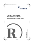
12-2158.fm Page 1 Wednesday, September 13, 2000 1:50 PM
Flat-Face Car CD Player
Please read before using this equipment.
Owner’s Manual
with Signal Level Meter Display
12-2158.fm Page 2 Wednesday, September 13, 2000 1:50 PM
ˆ Contents
Features .................................................................................................................................. 3
Installation .............................................................................................................................. 4
Preparing the Mounting Area ............................................................................................ 4
Routing Speaker Wires ..................................................................................................... 4
Removing the Shipping Screws ........................................................................................ 4
Making the Connections .................................................................................................... 5
Using an Adapter Harness ......................................................................................... 5
Connecting Ground, Power, and Optional Components ............................................ 5
Testing the Power Connections ................................................................................. 6
Connecting an Equalizer/Booster .............................................................................. 6
Connecting the Speakers .......................................................................................... 6
Completing the Connection ........................................................................................ 7
Testing the Connections ............................................................................................ 7
Mounting the CD Player .................................................................................................... 7
Removing the CD Player from the Dash .................................................................... 8
Mounting in Toyota, Nissan and Suzuki Vehicles ....................................................... 9
Installing/Removing the Control Panel ............................................................................ 10
Operation ..............................................................................................................................
Setting the Clock ......................................................................................................
Adjusting the Sound .................................................................................................
Resetting the Display ...............................................................................................
Radio Operation ..............................................................................................................
CD Player Operation .......................................................................................................
Playing a CD ............................................................................................................
Selecting a Track .....................................................................................................
Audible Search ........................................................................................................
Scanning the Tracks ................................................................................................
Repeat Play .............................................................................................................
Random Play ...........................................................................................................
10
10
11
11
11
12
12
12
13
13
13
13
Troubleshooting ...................................................................................................................
Care ................................................................................................................................
The FCC Wants You to Know .........................................................................................
CD Care Tips ..................................................................................................................
Replacing a Fuse ............................................................................................................
13
13
14
14
14
Specifications .......................................................................................................................
Radio .......................................................................................................................
CD Player ................................................................................................................
Signal Format ..........................................................................................................
General ....................................................................................................................
15
15
15
15
16
© 2000 RadioShack Corporation.
All Rights Reserved.
RadioShack and RadioShack.com are trademarks used by RadioShack Corporation.
2
12-2158.fm Page 3 Wednesday, September 13, 2000 1:50 PM
ˆ Features
Your RadioShack Flat-Face Car CD Player
has many practical, easy-to-use features,
and you can install it in almost any vehicle
using the supplied mounting bracket, hardware, and cables. Your CD player is easy to
operate, so you can concentrate on driving
safely.
Your CD player’s features include:
Detachable Flat-Face Front Panel — lets
you quickly remove and store the CD player’s control panel in the supplied carry case.
This discourages theft because the CD player cannot operate without the control panel.
Audible Search — lets you rapidly play a
CD forward or backward to locate a desired
track or section of a track.
Random Play — randomly selects and plays
tracks.
Repeat Play — automatically repeats the
current track.
Intro Scan — scans and plays the first 10
seconds of each track so you can find a specific track.
Audio Mute — lets you silence the CD player by pressing a single button.
Local/Distance Tuning Control — lets you
set the radio to stop on only strong local stations or both local and weaker, distant stations.
Bass, Treble, Fader, and Balance Controls — let you easily adjust the high and low
sounds and the balance between the left/
right and front/rear speakers, so you can tailor the sound to your preferences.
This CD player is made and tested to meet
exacting safety standards. It meets FCC requirements and complies with safety performance standards of the U.S. Department of
Health and Human Services.
Loudness Button — lets you boost the volume of sounds at very high and low ranges,
so you do not lose these sounds when the
CD player's volume is set very low.
Warnings:
Line-Out Jacks — make it easy to connect
an equalizer/amplifier.
Built-In Noise Suppression Choke — reduces the noise caused by your vehicle's
electrical system.
• This system employs a laser light beam.
Only a qualified service person should
remove the cover or attempt to service
this device, due to possible eye injury.
• The use of controls, adjustments, or procedures other than those specified
herein might result in hazardous radiation exposure.
Liquid Crystal Display With Clock —
shows the current operation of the CD and
tuner with bar spectrum signal level display.
Buzzer Alarm — alerts you when the speaker wires are connected in such a way that circuit damage could result.
Features
3
12-2158.fm Page 4 Wednesday, September 13, 2000 1:50 PM
ˆ Installation
Before you install your CD player, read all
the instructions in this owner’s manual. You
should be able to answer all of these questions about your vehicle’s electrical and
sound systems.
• Which terminal in my vehicle’s fuse box
supplies power even when the ignition is
turned off?
• Which terminal in my vehicle's fuse box
is for accessories?
• How do I connect a wire to the fuse box?
• Which CD player wires are line-level
outputs and which are speaker outputs?
Also, be aware that installation in your vehicle might require cutting or modifying your
vehicle.
We recommend that you install the CD player by temporarily connecting it to ground and
power, optional components, and your
speakers. Then test the connections, disconnect the CD player, mount it in your vehicle,
and reconnect it. The instructions in this
manual are arranged in this order.
• Be sure to avoid obstructions behind the
mounting surface.
Note: If the mounting area is too large, you
might be able to mount the CD player with an
in-dash installation kit, available at your local
RadioShack store. Follow the installation
kit’s instructions to mount the CD player.
ROUTING SPEAKER WIRES
If you install speakers, avoid routing the
speaker wires near moving parts or sharp
edges. You can usually route them along the
wiring channel beneath the vehicle’s door
facings by carefully removing the molding
that holds the carpet in place. After you route
the speaker wires, replace the molding.
REMOVING THE SHIPPING
SCREWS
The shipping screws help protect the CD
player from being damaged during shipment.
Before you mount the CD player, use a Phillips screwdriver to remove the two screws
from the top of the CD player.
Shipping
Screws
PREPARING THE
MOUNTING AREA
Before you mount the CD player, be sure you
have all the necessary materials. Then confirm that the CD player fits your vehicle’s
mounting area. This auto sound CD player
system is a DIN-E size unit that requires a
2124-inch high by 7124-inch wide by 71220inch
deep (57 × 184 × 190 mm) mounting area.
Cautions:
• Make sure your vehicle’s mounting area
is as level as possible.
4
Note: We suggest you tape the screws to the
back of the CD player in case you ever want
to mail or ship the CD player.
Installation
12-2158.fm Page 5 Wednesday, September 13, 2000 1:50 PM
MAKING THE
CONNECTIONS
the following procedure. Do not use a
common wire or chassis ground for any
speaker connection.
The supplied harness with the 14-pin connector includes all the lead wires you need to
connect the CD player to ground, power, optional components, and speakers.
Important: Do not cut these wires. If you cut
any wire, you cannot obtain a refund or exchange on this product. However, your RadioShack store will provide warranty service
if you cut a wire and find the product is defective.
You might need additional wire, depending
on your individual auto sound system, to
complete the connections. Your local RadioShack store carries a full line of wire and
wire management accessories.
Cautions:
• For added safety and to protect your CD
player, disconnect the cable from your
vehicle battery’s negative (–) terminal
before you begin.
• Be sure your speakers can handle 50
watts of power (25 watts per channel if
you are using one pair of speakers).
Each speaker must have an impedance
of at least 4 ohms. Your local
RadioShack store carries a full line of
speakers.
• You must connect the GROUND (–),
+12V TO IGNITION, and +12V TO BATTERY wires first, then make all other
connections as described in the following sections before you plug the harness
with the 14-pin connector into the CD
player. If you do not make connections
in the order shown, damage to the CD
player is possible if any wire connections are made incorrectly.
• You must connect a separate wire to
each speaker terminal as described in
The CD player’s buzzer alarm sounds if you
make an incorrect connection that could
damage the circuit.
Using an Adapter Harness
If you are replacing an existing CD player, or
if your vehicle has been factory-wired for
auto sound components, you might be able
to use an adapter harness to connect the
power and speakers. RadioShack sells
adapter harnesses for most vehicles.
Follow the directions that come with the
adapter harness to temporarily connect the
ground, power optional components and
speakers. Then go to “Completing the Connection” on Page 7.
Connecting Ground, Power, and
Optional Components
1. Disconnect the cable from your vehicle’s
negative (–) battery terminal.
2. Connect the black ground wire (with filter and fuse box) to a chassis ground,
such as a metal screw attached to a
metal part of the vehicle’s frame. Be
sure that the screw is not insulated from
the chassis by a plastic part.
3. Connect the red power wire (with in-line
fuse holder) to a point in your vehicle’s
fuse block that has power only when you
turn the vehicle’s key to either the
accessory (ACC) or the START position.
This prevents your vehicle’s battery from
being drained if you leave the CD player
on when you turn off the ignition.
4. Connect the yellow power/memory wire
(with filter and fuse box) to your vehicle
battery’s positive (+) terminal or to a
Installation
5
12-2158.fm Page 6 Wednesday, September 13, 2000 1:50 PM
point in your vehicle’s fuse block that
provides a continuous source of 12
volts. This provides power for the CD
player’s components, and continuous
power for the CD player’s memory when
the ignition is turned off.
5. Connect the blue/white wire to any
optional equipment designed to run from
a switched source that you want the CD
player to turn on and off (such as a
booster or a power antenna). To use this
wire you must first remove the insulation
and strip the wire.
This wire does not provide power to the
components. If you do not use this wire,
secure it with a wire tie and do not let it
touch metal.
Connecting an Equalizer/Booster
If you are connecting the CD player to a separate equalizer or booster, you need additional wires (not included).
To increase the total power output from your
system, connect an equalizer or booster to
the R (right) and L (left) line output jacks on
the back of the CD player (and the 14-pin
connector’s blue/white wire if you want to
use the CD player to turn the equalizer or
booster on and off).
Line Output
Jacks
Equalizer
or Booster
Testing the Power Connections
Temporarily connect:
Blue/White Wire
• the harness to the CD player’s 14-pin
wiring socket
Check the equalizer/booster's owner's manual for directions.
• your vehicle battery’s negative (–) cable
Connecting the Speakers
Turn on your vehicle’s ignition and install the
CD player’s control panel. See “Installing/Removing the Control Panel” on page 10. Verify
that the CD player works properly when the
display lights.
If the display does not light, immediately
turn off your vehicle’s ignition and disconnect your vehicle battery’s negative.
(–) cable. Then recheck your connections.
If the CD player works properly, remove the
CD player’s control panel and disconnect:
• your vehicle battery’s negative (–) cable
• the harness from the CD player’s 14-pin
wiring socket
To connect the harness to two pairs of
speakers:
1. Connect the white wire to the left front
speaker’s positive terminal. This terminal is usually marked with a plus (+) sign
or red mark.
2. Connect the white/black wire to the left
front speaker’s negative terminal. This
terminal might be marked with a minus
(–) sign or it might not be marked at all.
3. Connect the gray wire to the right front
speaker’s positive terminal.
4. Connect the gray/black wire to the right
front speaker’s negative terminal.
Then proceed with the installation.
6
Installation
12-2158.fm Page 7 Wednesday, September 13, 2000 1:50 PM
5. Connect the green wire to the left rear
speaker’s positive terminal.
when you play the radio (see “Radio Operation” on Page 11).
6. Connect the green/black wire to the left
rear speaker’s negative terminal.
If the display does not light and you do not
hear a station, immediately turn off your
vehicle’s ignition and disconnect your vehicle battery’s negative (–) cable. Then recheck your connections.
7. Connect the violet wire to the right rear
speaker’s positive terminal.
8. Connect the violet/black wire to the right
rear speaker’s negative terminal.
To connect the harness to one pair of speakers:
1. Connect the gray wire to the right
speaker’s positive terminal.
2. Connect the violet/black wire to the right
speaker’s negative terminal.
3. Connect the white wire to the left
speaker’s positive terminal.
4. Connect the green/black wire to the left
speaker’s negative terminal.
Completing the Connection
Connect the vehicle’s antenna cable to the
CD player’s antenna connector at the back of
the unit.
Make sure you have securely made all the
connections described in the preceding sections, then plug the harness connector into
the CD player’s 14-pin wiring socket. Reconnect the cable to the vehicle's negative (–)
battery terminal.
After you verify that the display lights and
you hear a station, follow the instructions in
“Mounting the CD Player.”
Caution: If you played a CD while testing the
connections, be sure to remove the CD from
the CD Player before continuing.
MOUNTING THE CD PLAYER
Be sure you verify that the CD player is connected properly (see “Testing the Connections” on Page 7) before mounting in the
dash.
1. Make sure the ignition is turned off, then
disconnect the cable from the vehicle’s
negative (–) battery terminal.
2. Disconnect the 14-wire harness and disconnect the antenna.
3. Press REL on the upper right corner of
the control panel to remove the control
panel.
Testing the Connections
Reset your CD player’s display (see “Resetting the Display” on Page 11), then install
your CD player’s control panel (see “Installing/Removing the Control Panel” on
Page 10). The display should light, and you
should hear a station through the speakers
Installation
REL
7
12-2158.fm Page 8 Wednesday, September 13, 2000 1:50 PM
4. Take off the plastic trim ring by lifting the
top of the trim ring.
9. To further secure the CD player, use the
supplied hardware to attach one end of
the supplied metal strap to the mounting
bolt on the back of the CD player. If necessary, bend the metal strap to fit your
vehicle’s mounting area. Then use the
supplied sheet metal screw to attach the
other end of the strap to a solid metal
part of the vehicle under the dashboard.
This strap also helps ensure proper
electrical grounding of the CD player.
Metal Strap
5. Insert the supplied keys into the slots on
both sides of the CD player. Push them
all the way in, then slide the CD player
out of the sleeve.
Washers
Keys
6. Insert the sleeve into the dash. Then
secure it by bending out all the tabs with
a flat-blade screwdriver.
10. Reconnect the cable to the vehicle’s
negative (–) battery terminal. Then
replace the trim ring and install the CD
player’s control panel (see “Installing/
Removing the Control Panel” on
Page 10).
You might need to reset the CD player’s
clock after you reconnect the cable to the vehicle battery. (See “Setting the Clock” on
Page 10.)
Removing the CD Player from the
Dash
1. Make sure the ignition is turned off and
disconnect the cable from the vehicle’s
negative (–) battery terminal.
8
7. Reconnect the harness to the CD
player’s 14-pin wiring socket, then
reconnect the antenna.
2. If the metal strap is used, remove the
nut holding it to the back of the CD
player.
8. Slide the CD player into the sleeve until
it locks in place.
3. Press REL to remove the CD player’s
control panel.
Installation
12-2158.fm Page 9 Wednesday, September 13, 2000 1:50 PM
4. Remove the plastic trim ring by lifting the
top of the trim ring.
7. Disconnect the 14-wire harness and the
antenna.
5. Insert the supplied keys into the slots at
both sides of the CD player, and slide
the CD player out of the dash.
8. If you are mailing or shipping the CD
player, reinstall the shipping screws in
the top of the CD player.
6. Remove the keys from the slots.
9. Reconnect the cable to the vehicle’s
negative (–) battery terminal.
Mounting in Toyota, Nissan and Suzuki Vehicles
If your vehicle is a Nissan, Toyota, or Suzuki, follow these mounting instructions or contact
your nearest Toyota, Nissan or Suzuki dealer for installation information.
Use the screw holes marked T (Toyota), N (Nissan) or S (Suzuki), located on both sides of the
CD player to fasten the CD player to the factory radio mounting brackets supplied with your vehicle.
Side view showing Screw
Holes marked T, N, or S
Vehicle Mounting
Brackets and Screws
Vehicle Mounting
Brackets and Screws
Hook and Screws
1. Use a Phillips screwdriver to loosen and
remove the hook’s screws on the front
left and right side of the CD player.
Note: The mounting box, outer trim ring, and
sleeve are not needed for this type of installation.
2. Align the screw holes on the bracket
with the screw holes on the CD player,
then tighten the screws on each side.
Screw Selection Guide
3. Fasten with the supplied truss screws (5
× 5 mm) or flush surface screws (4 × 5
mm), depending on the shape of the
screw holes in the bracket.
Screw Type
Quantity
Car Type
M 5 × 5 mm
4
T (Toyota),
N (Nissan)
M 4 × 5 mm
4
S (Suzuki)
Installation
9
12-2158.fm Page 10 Wednesday, September 13, 2000 1:50 PM
INSTALLING/REMOVING
THE CONTROL PANEL
sure the pins in the recess fill the slots in
the edge of the control panel.
CD Player
Control Panel
The CD player's control panel must be in
place for the CD player to operate. When you
remove it, the display turns off and the CD
player cannot be used. This is a simple but
effective security measure. Any stored stations remain in memory when the control
panel is removed.
Follow these steps to install the control panel:
1. Insert the left edge of the control panel
into the left edge of the recess. Make
2. Gently push the right edge of the control
panel into the recess until you hear a
click.
To remove the control panel, press REL. The
control panel swings out. Remove it and
store it in the supplied carry case.
Caution: To keep the metal connecting pins
clean, do not touch the connecting pins in the
recess or on the back of the control panel.
ˆ Operation
TRACK +
VOL +
EJ
REL
TUNE
SEL
VOL –
PWR
MODE
TRACK –
MUTE
(Play)
LOC / RPT
LOUD / RND
DSP
BND
M/S / INT
Caution: Do not change your CD player’s
settings in heavy traffic or during hazardous
driving conditions.
repeatedly press VOL + until the correct
hour displays then repeatedly press VOL
– until the correct minute displays.
To turn on the CD player, press PWR. The
buttons and display light. To turn off the CD
player, press PWR again.
Note: The PM indicator appears at 12 noon
and disappears at 12 midnight.
Setting the Clock
1. Press PWR. Hold down DSP for about 2
seconds until the display flashes, then
10
Press DSP while the radio or a CD is playing
to display the clock. To return to the display,
press DSP or BND (while the radio is playing)
or MODE to choose radio or CD mode. The
CD player also automatically returns to the
Operation
12-2158.fm Page 11 Wednesday, September 13, 2000 1:50 PM
display after about 5 seconds if you do not
press any buttons.
Resetting the Display
Adjusting the Sound
1. Press VOL + or VOL – to adjust the volume or repeatedly press SEL until VOL
appears on the display. Then adjust the
volume by pressing VOL + or VOL –.
Warning: To protect your hearing, do
not listen at high volume levels. Slowly
increase the volume to a comfortable listening level.
Note: The player is initially set to volume mode.
RESET
Use a ballpoint pen to press RESET at the top
left side of the inside panel:
• during initial installation, once all wiring
is completed
2. Repeatedly press SEL until BAS
appears, then press VOL + or VOL – to
adjust the bass level.
3. Repeatedly press SEL until TRE
appears, then press VOL + or VOL – to
adjust the treble level.
4. Repeatedly press SEL until BAL
appears, then press VOL + or VOL – to
adjust the left/right sound balance. BAl
(balance left) or BAr (balance right)
appears.
5. Repeatedly press SEL until FAd
appears. Then press VOL + or VOL – to
adjust the sound balance between the
front and rear speakers. FAF (fade
front) or FaR (fade rear) appears.
• if the stereo’s controls do not operate
• if an error symbol (ER-1 through ER-8)
appears on the display
RADIO OPERATION
1. Press PWR. The radio automatically
tunes to the last station and band
selected.
2. Press BND to select the desired band,
either FM (FM appears) or AM (AM
appears).
3. Rotate TUNE to adjust the frequency.
Notes:
6. To increase bass output, press LOUD.
LOUD appears. To return bass output to
normal, press LOUD again and LOUD
disappears.
To temporarily silence the CD player, press
MUTE. MUTE appears. To resume listening,
press MUTE again and MUTE disappears.
Operation
• In FM mode, the tuner stops on both
strong and weak stations. To limit seek
tuning to only strong stations, press LOC
until LOC appears.
• To improve reception of weak FM stations, press M/S until ST disappears.
The sound is no longer in stereo, but the
reception should improve. To return to
stereo sound, press M/S again and ST
11
12-2158.fm Page 12 Wednesday, September 13, 2000 1:50 PM
appears. If you get a steady FM signal,
appears to the right side of ST.
CdP (CD play), then TRACK 01, and
Adjust the CD player’s controls to your listening preference (see “Adjusting the Sound” on
Page 11).
• If a CD is already in the CD player,
simply press MODE to play the CD.
The CD player displays the number of
the last track you played, and the CD
starts to play from that track.
the CD plays from Track 1.
CD PLAYER OPERATION
• After the CD player plays the entire
CD, it automatically repeats all tracks,
starting with Track 1.
Cautions:
• Play only CDs that have this mark on
them:
• The CD player has a wide dynamic
range. As a result, if you turn your CD
player’s volume up too high during lowvolume sections of a program, your
speakers might be damaged when a
sudden loud passage occurs.
• If the CD player is jolted during play, the
rotation speed might suddenly change
or the CD player might make an unusual
noise. This is not a malfunction.
• Driving on bumpy roads may cause the
CD player to skip. Performance will
improve after a short break-in period.
Skipping does not damage CDs.
Note: If you turn off your vehicle’s ignition or the CD player when a CD is
loaded, you must wait about 5 seconds
after turning the ignition back on before
operation.
2. Repeatedly press VOL + or VOL – to
increase or decrease the volume.
Note: See “Adjusting the Sound” on
Page 11 for information about changing
the CD player’s other settings.
3. Press
Press
4.
• If you eject a CD while it is playing
and do not remove it from the CD
player, the CD player automatically
draws the CD back in after about 5
seconds.
• Do not expose the CD player to
extremely high or low temperatures.
Playing a CD
1. Insert a CD, label side up, into the slot.
The radio stops. LOAdcd appears, then
12
To remove a CD from the CD player,
press EJ.
Notes:
• Moisture and high humidity can cause
malfunction of the CD player. Turn on
the vehicle’s heater and allow moisture
to evaporate before use.
• Do not drive with an ejected CD in the
slot.
. to pause play.
. flashes.
. again to resume play.
• If you eject a CD and remove it from
the CD player, the CD player
switches to radio operation.
Selecting a Track
To select a track on the loaded CD, press
TRACK + during play to advance to the next
track or TRACK – to go back to the beginning
of the current track. Repeatedly press
Operation
12-2158.fm Page 13 Wednesday, September 13, 2000 1:50 PM
TRACK + or TRACK – to select the next or
2. Press INT again to resume normal play.
previous track.
Repeat Play
Audible Search
To search for a particular section within a
track, hold down TRACK + or TRACK – during
play. The CD player rapidly plays the CD either forward or backward, and the volume
lowers. When you hear the section you want,
release TRACK + or TRACK – to resume normal play.
1. To repeat a track, press RPT during play.
When the track ends, it automatically
repeats.
2. Press RPT again to resume normal play.
Random Play
You can set the CD player to randomly select
and play tracks from the loaded CD.
Scanning the Tracks
You can set the CD player to play the first 10
seconds of each track on the loaded CD, so
you can find the track you want to hear.
1. To begin scanning, press INT.
1. To begin random play, hold down RND
for about 2 seconds until RND appears.
2. To stop random play, hold down RND for
about 2 seconds until RND disappears.
ˆ Troubleshooting
If your CD player is not working properly, it
displays an error indicator (ER-1 through
ER-8). Press EJ to eject the CD and check it
for scratches and condensation (see “CD
Care Tips” on Page 14). Reload the CD and
try again to play it, or try a different CD. If the
CD player still does not operate properly,
take it to your local RadioShack for assistance.
CARE
Your CD Player is an example of superior
design and craftsmanship. The following
suggestions will help you care for the CD
player so you can enjoy it for years.
• Keep the CD player dry. If it gets wet,
wipe it dry immediately. Liquids can contain minerals that can corrode electronic
circuits.
• Use and store the CD player only in normal temperature environments. Temperature extremes can shorten the life of
electronic devices and distort or melt
plastic parts.
• Keep the CD player away from dust and
dirt, which can cause premature wear of
parts.
• Handle the CD player gently and carefully. Dropping it can damage the circuit
boards and case and can cause it to
work improperly.
• Wipe the CD player with a damp cloth
occasionally to keep it looking new. Do
not use harsh chemicals, cleaning solvents, or strong detergents to clean the
CD player.
Modifying or tampering with the CD player’s
internal parts can cause a malfunction and
might invalidate your CD player’s warranty
Troubleshooting
13
12-2158.fm Page 14 Wednesday, September 13, 2000 1:50 PM
and void your FCC authorization to operate
it. If your CD player is not performing as it
should, take it to your local RadioShack for
assistance.
THE FCC WANTS YOU TO
KNOW
Your CD player might cause TV or radio interference even when it is operating properly.
To determine whether your CD player is
causing the interference, turn off your CD
player. If the interference goes away, your
CD player is causing it. Try to eliminate the
interference by:
• moving your CD player away from the
receiver
• contacting your local RadioShack store
for help
If you cannot eliminate the interference, the
FCC requires that you stop using your CD
player.
CD CARE TIPS
Even though a CD is very durable, you
should handle it with care. We recommend
the following precautions.
• Keep the CD in its protective case or
sleeve when you are not playing it.
• Handle a CD by its edges to avoid fingerprints which can prevent the CD
player’s laser beam from accurately
reading the CD. Your local RadioShack
store sells a suitable CD cleaner kit.
• Do not write on either side of the CD,
particularly the non-label side. (Signals
are read from the non-label side.)
• Keep the CD dry. A water drop can act
as a lens and affect the laser beam’s
focus.
14
• If you park your vehicle in the sun, temperatures inside the vehicle can easily
reach levels that could damage your
CDs. To prevent heat damage, avoid
leaving your CDs in your vehicle.
If a CD skips when you try to play it, it might
be scratched. Your local RadioShack store
sells a Scratch ’n’ Fix kit that might help remove the scratch and stop the skip.
REPLACING A FUSE
If the CD player does not operate, you might
need to replace the red power wire’s 0.5A
fuse with the supplied spare fuse. If the clock
resets or stored stations are lost when the ignition is off, you might need to replace the
black ground wire’s/yellow continuous power wire’s 5A fuse inside the filter and fuse
box with the supplied spare fuse. Check both
fuses.
Note: A fuse’s amp rating is stamped on its
metal end. Be sure to use the correct spare
fuse to replace a failed fuse.
1. Disconnect the cable from the vehicle
battery’s negative (–) terminal.
2. Unlatch the two latches on the red
power wire’s fuse holder until it springs
apart.
3. Pull up the latch on the filter and fuse
box until the box springs open.
4. If either fuse is blown, replace it. Use
only 11/4 × 1/4-inch fast-acting fuses with
the proper rating. The red power wire’s
fuse must be 0.5 amps, and the yellow
continuous power wire’s fuse must be 5
amps.
Caution: Make sure you replace a fuse
only with another fuse of the same rating.
Troubleshooting
12-2158.fm Page 15 Wednesday, September 13, 2000 1:50 PM
5. Reassemble the red power wire’s fuse
holder by squeezing it together until it
latches.
6. Reassemble the filter and fuse box by
closing it then pushing the latch until it
clicks.
7. Reconnect the cable to the vehicle battery’s negative (–) terminal.
ˆ Specifications
Radio
FM (Nominal)
AM (Nominal)
Frequency Range
88–108 MHZ
530–1710 kHz
Frequency Response
(±3 dB) 50-12000 Hz
N/A
IF Rejection
100 dB
80 dB
Image Rejection
55 dB
50 dB
Selectivity
30 dB
30 dB
Signal-to-Noise (S/N) Ratio
60 dB
45 dB
CD Player Separation
30 dB
N/A
Usable Sensitivity
5.0 µV (3% THD)
32 µV (20 dB S/N)
CD Player
Frequency Response (–3 dB) .................................................................................................. 50-15000 Hz
Signal-to-Noise Ratio .......................................................................................................................... 65 dB
Harmonic Distortion [Ref] ...................................................................................................................... 0.3%
CD Used (diameter) ........................................................................................................................... 5-inch
(120 mm)
Signal Format
D-A Conversion ........................................................................................................................... 1Bit Linear
Transmission Bit Rate .............................................................................................................. 1.4 Mbit/Sec
Sampling Frequency ........................................................................................................................ 8 Times
Pick-Up System ................................................................................................................... Optical Pick-Up
Optical Source ..................................................................................................................................... Laser
Number of Channels ............................................................................................................................ 4-Ch
Specifications
15
12-2158.fm Page 16 Wednesday, September 13, 2000 1:50 PM
General
Power Source ....................................................................................................... 12V DC Negative Ground
Speaker Output Impedance ..................................................................................................... 4 or 8 Ohms
Maximum Power:
One Pair of Speakers (Max Output) ......................................................................... 25 Watts RMS/Channel
Power Output (10% THD @ 1kHz) .................................................................................. 16W × 2 or 5W ×4
Two Pairs of Speakers (Max Output) ......................................................................... 7 Watts RMS/Channel
1
Chassis Size (HWD) ............................................................................................... 2 /4 × 71/4 × 71/2 Inches
(59 x 181 x 178 mm)
Weight ................................................................................................................................................. 3.9 lb
(1.76 kg)
Specifications are typical; individual units might vary. Specifications are subject to change and improvement without notice.
Limited One-Year Warranty
This product is warranted by RadioShack against manufacturing defects in material and workmanship under normal
use for one (1) year from the date of purchase from RadioShack company-owned stores and authorized RadioShack franchisees and dealers. EXCEPT AS PROVIDED HEREIN, RadioShack MAKES NO EXPRESS WARRANTIES AND ANY IMPLIED WARRANTIES, INCLUDING THOSE OF MERCHANTABILITY AND FITNESS FOR
A PARTICULAR PURPOSE, ARE LIMITED IN DURATION TO THE DURATION OF THE WRITTEN LIMITED WARRANTIES CONTAINED HEREIN. EXCEPT AS PROVIDED HEREIN, RadioShack SHALL HAVE NO LIABILITY OR
RESPONSIBILITY TO CUSTOMER OR ANY OTHER PERSON OR ENTITY WITH RESPECT TO ANY LIABILITY,
LOSS OR DAMAGE CAUSED DIRECTLY OR INDIRECTLY BY USE OR PERFORMANCE OF THE PRODUCT OR
ARISING OUT OF ANY BREACH OF THIS WARRANTY, INCLUDING, BUT NOT LIMITED TO, ANY DAMAGES
RESULTING FROM INCONVENIENCE, LOSS OF TIME, DATA, PROPERTY, REVENUE, OR PROFIT OR ANY INDIRECT, SPECIAL, INCIDENTAL, OR CONSEQUENTIAL DAMAGES, EVEN IF RadioShack HAS BEEN ADVISED
OF THE POSSIBILITY OF SUCH DAMAGES.
Some states do not allow limitations on how long an implied warranty lasts or the exclusion or limitation of incidental
or consequential damages, so the above limitations or exclusions may not apply to you.
In the event of a product defect during the warranty period, take the product and the RadioShack sales receipt as
proof of purchase date to any RadioShack store. RadioShack will, at its option, unless otherwise provided by law: (a)
correct the defect by product repair without charge for parts and labor; (b) replace the product with one of the same
or similar design; or (c) refund the purchase price. All replaced parts and products, and products on which a refund
is made, become the property of RadioShack. New or reconditioned parts and products may be used in the performance of warranty service. Repaired or replaced parts and products are warranted for the remainder of the original
warranty period. You will be charged for repair or replacement of the product made after the expiration of the warranty period.
This warranty does not cover: (a) damage or failure caused by or attributable to acts of God, abuse, accident, misuse, improper or abnormal usage, failure to follow instructions, improper installation or maintenance, alteration, lightning or other incidence of excess voltage or current; (b) any repairs other than those provided by a RadioShack
Authorized Service Facility; (c) consumables such as fuses or batteries; (d) cosmetic damage; (e) transportation,
shipping or insurance costs; or (f) costs of product removal, installation, set-up service adjustment or reinstallation.
This warranty gives you specific legal rights, and you may also have other rights which vary from state to state.
RadioShack Customer Relations, 200 Taylor Street, 6th Floor, Fort Worth, TX 76102
We Service What We Sell
RadioShack Corporation
Fort Worth, Texas 76102
12/99
12-2158
09A00
Printed in China