1
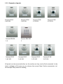
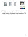
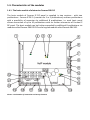
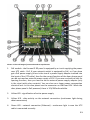
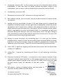
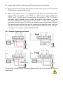
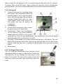
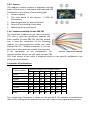
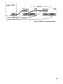
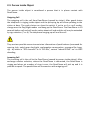
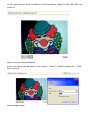
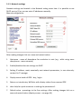
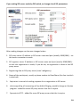
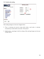
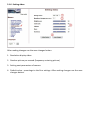
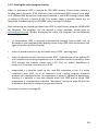
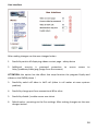
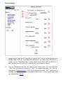
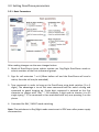
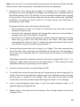
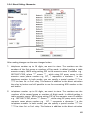
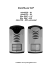
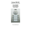
Fermax IP DP SIP based VoIP video door phone panel Fermax PBX EXP Fermax PBX KEY Fermax PBX EA User and installation guide Manual version V3.4 19-1-2011 Valid for firmware of the VoIP module - V1.52 Welcome Congratulations on purchasing the door phone panel Fermax IP DP "VoIP Door Phone", which is a SIP based VoIP version of "Fermax PBX DP" analog door phone panel. This door phone can satisfy your need of communication with visitors at the entrance to the building, to your company or at the entrance of your house. VoIP means "Voice over Internet Protocol" - the door phone is connected to the computer network and enables both P2P (peer to peer) connection - i.e. it calls to an IP address of other VoIP device directly or it is registered to a SIP server, then it calls a phone number. There can be assigned up to two 25 digit numbers including characters "* ", "#". The basic module of the door phone always contains 2 pushbuttons and optionally the first expansion, 8 pushbutton C module. The combination of Fermax New Cityline panels enable the sets of door phone with 1 to 10 pushbuttons just by using the basic electronics module of Fermax IP DP. You can also expand the whole system by the 8 pushbutton expansion module Fermax PBX EXP up to the limit of 64 pushbuttons. The basic module can contain a colour camera, optionally there can be an add-on speaker module with an amplifier Fermax PBX EA, which is used for very noisy areas. The Fermax New Cityline panels are rich with an add ons. For example the panels offer installations on the surface or flush mounted, they can be used both indoors and outdoors, there can be add-on roofing used, etc. The Fermax IP DP door phone panel is powered by 12V of the power supply, which can also be used for powering the electrical lock of the door. The Fermax IP DP is also PoE powered (Power over Ethernet). The features of the door phone are similar to a hands-free telephone. Among basic features you can find the possibility of opening up to two doors via connected electrical locks and also an easy WEB based programming. The producer improves the SW (firmware) of the door phone panel continuously. Fermax IP DP panel enables uploading the latest firmware version via a standard PC. To get the latest firmware, please write to [email protected] All necessary steps for this process can be found on page 30. We strongly recommend using the latest firmware version, which brings new features and solves various possible issues of the continuosly improving Fermax door phone panel. At http://www.provu.co.uk/ you can also find the latest version of user and installation guide. Contents 1 Basic description 1.1 Features 1.2 Used Terminology 1.3 Assembly of Panels 1.4 Characteristics of the modules 5 2 DoorPhone VoIP Operation 2.1 Signaling Overview 2.2 Visitor at the Door 2.3 Person Inside Object 21 3 Programming of Parameters 3.1 Basic VoIP settings 3.2 Setting DoorPhone parameters 24 4 Technical Parameters 4.1 Electrical Parameters 4.2 Parameters of video 47 3 1. Basic description 1.1. Features IP (SIP) modular system with built-in colour camera P2P or SIP proxy mode (PBX network system) 1-64 pushbuttons Two 25-digit numbers on each pushbutton Waterproof pushbuttons with impregnation IP66, gold plated contacts Pushbuttons are manufactured in zamak and a natural chromed finish Panel is made of highly weather resistant anodised aluminium Easy installation for outdoor or indoor use Pernament card slot lighting (switchable by jumper) Card slot lighting by low consumption, max. duration LEDs Commands can be used for a doophone two or a single digit (command 55 is reduced to 5 so that we save * 5 instead of the original 55) 2 relays for two independent electrical locks Codelock feature by using pushbuttons Up to six codelock numerical passwords (2-6 digits) Basic panel set is supplied in 2 pushbutton version with colour camera and surface mount installation box (ref. 1CP201 + ref. F7061) Basic panel ref. 1CP201 contains the first expansion module for 8 pushbuttons Power supply 12V or PoE (Power over Ethernet) PoE allows using a low consumption el. lock PopUp SW for on-line monitoring of door entrance, possiblity to open el. locks via PC WEB based programming Integrated heating of the electronic circuit board OS Linux 2.6 USB connection of integrated camera - USB Guest 1.1 Software GSPCA for video transmission to web browser in PC - W3CAM (JPEG, RTSP stream) and stream H.263 Flush or surface mounting Automatic illumination for camera by white LEDs 1.2. Used terminology • • • • • • • • • • • • • • Ethernet is a family of frame-based computer networking technologies for local area networks (LANs LAN - a local area network (LAN) is a computer network covering a small physical area, like a home, office, or small groups of buildings, such as a school, or an airport. 10Base-T - 10 Mbit/s , it uses 8 position modular connectors, usually called RJ45 in the context of Ethernet over twisted pair. The cables usually used are four-pair twisted pair cable (though 10BASE-T and 100BASE-TX only actually require two of the pairs). Each of the standards support both full-duplex and half-duplex communication. According to the standards, they all operate over distances of up to 100 meters. 100Base-TX - so called Fast Ethernet, two pairs of UTP or STP cable, category 5. Twisted pair cabling is a type of wiring in which two conductors (the forward and return conductors of a single circuit) are twisted together for the purposes of canceling out electromagnetic interference (EMI) from external sources; for instance, electromagnetic radiation from unshielded twisted pair (UTP) cables, and crosstalk between neighboring pairs. UTP, Unshielded Twisted Pair STP,Shielded Twisted Pair - the cabling includes metal shielding over each individual pair of copper wires. This type of shielding protects cable from external EMI (electromagnetic interferences). WEB - World Wide Web (WWW, or web) - a world-wide application of HTTP internet protocol HTTP (Hypertext Transfer Protocol) is an internet protocol used originally for exchanging hypertext documents in HTML format. USB (Universal Serial Bus) - modern way of connecting external devices to the computer. Video codek ("coder and decoder") - compression H.263 is derived from MPEG-4, H.264 is a coder for MPEG-4 AVC format. MPEG-4 is a type of video compression - decreasing of data stream video sequence JPEG is a standard method of loss compression used for saving digital images Voice over Internet Protocol (VoIP) is a technology enabling transmission of digitalised voice inside the packej of protocols family UDP/TCP/IP via computer network. I tis used for making phone calls via Internet, Intranet or any other kind of data connection TCP/IP contains a set of protocols for communication in the computer network and it is the main protocol of Internet 5 • • • • • • IP address is a number, which clearly identifies a network interface in the computer network, which uses IP protocol DHCP (Dynamic Host Configuration Protocol) is an application protocol from the family of TCP/IP. It is used for automatic assigning of IP addresses to individual personal computers in the PC networks, thus simplyfing their administration Internet is a word-wide system of mutually connected computer networks Intranet is a computer network similar to Internet, but it is a private one. That means it is just used for small user groups (e.g. employees of a company ). PoE (Power over Ethernet) is powering via data network cable, with no need of bringing the power supply via a separate cable NTP (Network Time Protocol) is a protocol for synchronisation of internal computer clock 1.3. Assembly of panels The building blocks of Fermax IP DP are the basic panels which differ by its size, number of pushbuttons, if the visit card has got two or one pushbuttons. 1.3.1. Terminology and orientation in panels 4 CP 204 (item number) as a representative of terminology. It is a panel with height of 199mm. It contains an audio module, a colour camera and two times 4 pushbuttons, i.e. 8 pushbuttons in total. first digit: 1 - 9 defines the height of the whole panel, the width of all panels is 130mm. 1 - 128mm 2 - 151mm 3 - 175mm 4 - 199mm 5 - 246mm 6 - 294mm 7 - 341mm 8 - 389mm 9 - 436mm group of letters: defines basic HW features of panel: A - audio panel C - audio panel with a camera P - panel with pushbuttons V - panel with a window W - panel with two windows first digit after letters: 1 / 2 - defines number of pushbuttons at visit card 1 (on the right) or 2 (on the left or right) next two digits: 01 - 15 - number of visit cards. If multiplied by the previous digit, then we get a number of pushbuttons on the panel By this marking one compact panel is defined. The panel can be expanded by other panels vertically or more optimally, in a horizontal direction. In case of horizontal expansion, then it is necessary to use the same height of panels (defined by the first digit of the item number). 7 1.3.1. Examples of panels Fermax IP DP 1 AP 201 Fermax PBX EA 1A Fermax IP DP 2 AP 202 Fermax IP DP 1 AP 101 Fermax IP DP 1 CP 201 Fermax IP DP 1 CP 101 Fermax PBX KEY 1 Fermax IP DP 2 AP 201 Fermax IP DP 2 CP 202 Fermax IP DP 2 CP 102 All panels can be mounted either on the surface or they can be flush mounted. In the latest catalogue of Fermax you can choose the correct New Cityline accessories incl. for example the protective roofing. Fermax IP DP panels can be equipped with an additional time switch called "TimeRelay". It is used for an expansion of the number of switches. It is programmable. Based on switching of one of the two switches in the Fermax IP DP panel, the TimeRelay can simulate e.g. sequent opening of the door or alternatively you can connect the exit button. 9 1.4. Characteristics of the modules 1.4.1. The basic module of electronics Fermax PBX DP The basic module of Fermax IP DP panel is supplied in two versions - with two pushbuttons - Fermax IP DP-2 (a version for 1 or 2 pushbuttons) and two pushbuttons with a possibility of expansion by additional 8 pushbuttons, i.e. each basic panel allows connection of up to 10 pushbuttons with no further accessories of Fermax IP DP panel. The basic module can be further expanded by additional 8 pushbuttons via modules called Fermax PBX DP EXP and a keypad module called Fermax PBX KEY. Picture 1 Schematics of connection and set-up elements Picture 2 The real image of connection and set-up elements 1. PoE module - the Fermax IP DP panel is equipped by a circuit supplying the power over UTP cable - PoE. If your network switch is equipped by PoE, or if you have got a PoE power supply (a box in the size of a power supply adapter inserted into the input of the UTP cable), then for the correct function of the door phone panel you do not need an external power supply of 12V. If you use an electrical lock for opening the door, then you need to use an external power supply adapter (only in the circuit with relay contacts). You can also use a lower power consumption electrical lock. In this case please use the connector on IPNCmod 12V. When the door phone panel is PoE powered, there is 12V/350mA available. 2. Yellow LED - signallisation of active power supply 3. Yellow LED - data activity on the network connection (continuous light during data transmission) 4. Green LED - network connection (Ethernet) - continuous light in case the UTP cable is connected correctly. 11 5. Loudspaker loudness SPK - by the trimmer you can set a desired loudness of the loudspeaker. In case you need to further increase the power output of the loudspeaker, you can use an add-on module with an amplifier Fermax PBX EA. 6. Loudspeaker connection SPK 7. Microphone connection MIC - attention on the right polarity!!! 8. MIC loudness setting - by the trimmer you set the desired level of loudness of the microphone. 9. Settings of Echo cancellation. Fermax IP DP door phone panel is a hands-free telephone. During the phone call the signal from a loudspeaker comes back to the microphone and it comes with a delay to the calling party (that is caused by a digital conversion and transmission of the signal). For this reason the door phone panel is equipped by an echo cancellation circuit. It is neccessary to pay more attention during the setting of the echo cancellation circuit. The right setting of echo cancellation means at what level of sound the mic turns off in Fermax IP DP in order to avoid returning the delayed sound. 10. Setting of sensor sensitivity on surrounding light. It is valid only for modules equipped with a camera. If case the surrounding light decreases below at certain level (it is set by this trimmer), then the camera is equipped by a white LED diodes for extra illumination. These LEDs are activated during a phone call only. 11. Green LED - it signals an outgoing call (the door phone panel calls the destination number or IP address) 12. Yellow LED - it signals an incomming call (there is a call comming to the door phone) 13. Ethernet connection (UTP cable) - a connection to the computer network. If you have got a network switch with PoE or a PoE power supply (a box in the size of a power supply adapter inserted to the input of UTP cable), then you do not need an extra power supply for operation of the door phone panel. 14. DIP switch - setting of default values and the mode of Fermax IP DP door phone via a DIP switch. 1: reserve (unused) 2: mode switching P2P / SIP server 3: basic settings - resets all values to factory settings except for the memory of numbers 4: sets the starting IP address to 192.168.1.250 All changes show always after turning off and turning on of the power supply (restart). The DIP switch 3 and 4 needs to be switched back to "on" position after the start of VoIP module. Otherwise after the restart the set parameters or the new IP address are rewritten back to the default mode. 15. Output of 12VDC (max. 350mA!). This output is used primarily for supplying the power to the lowconsumption electrical lock when PoE is used. 16. Switching contact 2 (NO= normally open, NC= normally closed and COM= common output of the switch). 17. Connector 8 - for connecting 8 pushbuttons (integrated expansion). For connection please use an interconnection cable Fermax PBX CC8. Each colour of the cable is assigned exactly for a specific pushbutton see picture 3. Connection of pushbuttons: black = 3rd pushbutton orange = 4th pushbutton green = 5th pushbutton white = 6th pushbutton red = 7th pushbutton yellow = 8th pushbutton brown = 9th pushbutton blue = 10th pushbutton Picture 3 Cable Fermax PBX CC8 The numbers of pushbuttons begin with 3, because the first two buttons are integrated on the basic panel. 18. Connector 5 - connection of the 8-pushbutton expansion Fermax PBX EXP or the keypad Fermax PBX KEY. The connection is done via Fermax PBX CC5 cable. It is a data connection only. Power supply of illumination and the common output is on the Connector 3. 19. Connector 3 - it is used for connection of the power supply and the common output of the pushbuttons. The original Fermax cable is used (Fermax PBX CC3). 13 20. Jumper Light enables switching on/off the illumination of visit cards. 21. Switching contact of the 2nd switch (NO=normally open, NC=normally closed and COM=common output of the switch). 22. When using Fermax IP DP, it is suggested to use either an alternating power supply voltage min. 10VAC - max. 15VAC or a direct power supply voltage min. 12VDC - max. - 18VDC. which is connected to the connector "12V". The load of the power supply depends on the number of modules used, because it is used also for powering the illumination of visit cards - if the max. number of pushbutton panels is used, the power consumption does not go beyond 500mA. This power supply can be also used for powering the electrical locks, then you need to calculate alsko with the power consumption of electrical locks. Usually it is enough to use a power supply of 12VAC/1A÷2A. 1.4.2. Example of switches connection The switching contact of relay is separated galvanically from other circuits of the door phone panel. When using PoE, the output of 12V is connected galvanically with the PC network. Therefore when using PoE power supply, please pay attention during manipulation and installation. The circuit is connected galvanically with the computer network!!! 1.4.3. Front panel 1. Assembly openings for mounting of the front panel. After installation of the top opening, please cover it with the plastic cover with Fermax logo. When bottom opening please cover with the grey, round plastic cover. Both covers incl. the screws are part of delivery as accessories. 2. Loudspeaker. 3. Camera with illumination and a sensor for switching on the illumination. 4. Pushbuttons. These two pushbuttons can be found on the basic electronics module (the main PCB). In case you use a panel without these first two pushbuttons, then please leave them out during the programming process (pushbuttons 1 and 2). 5. Visit card. The exchange of visit card is described later on in the manual. The visit card is illuminated by white LEDs (they can be switched off). You can also find a red LED under the visit card - it is used for signallisation of the door phone panel status. 6. Microphone. 1.4.4. Exchange of visit cards The visit cards are disassembled from the front of the door phone panel as shown on the picture. Please use a tool carefully, do not damage the front panel or the cover of visit cards. The cover of visit cards is a tub into which you place the paper with descriotion (the visit card). 15 1.4.5. Camera The module of colour camera is integrated into the panel of Fermax by a sub-board with mounted LED illumination and a sensor of surrounding light. 1. Camera module 2. The main board of the camera - 3 LEDs for illumination 3. Mounting column for the main board 4. Sensor of surrounding illumination 5. Mounting of the main board 1.4.6. Expansion module Fermax PBX EXP The expansion module has got two connectors CC5, one is used for connection towards the basic module (Fermax PBX DP) and the second one is used for connection of the following module. For interconnection please use cable Fermax PBX CC5. Besides connectors 5, you can also find on the expansion module the connector Picture 4 Cable Fermax PBX CC8 8 for connection of the pushbuttons. For interconnection please use the cable Fermax PBX CC8. Each colour of the cable is assigned exactly to the specific pushbutton, see picture for more details. Connection of pushbuttons: Colour of wire Black Orange Green White Red Yellow Brown Blue Position number on Fermax PBX EXP 1 2 3 4 5 6 11 19 27 35 43 51 12 20 28 36 44 52 13 21 29 37 45 53 14 22 30 38 46 54 15 23 31 39 47 55 16 24 32 40 48 56 17 25 33 41 49 57 18 26 34 42 50 58 7 59 60 61 62 63 64 The numbering of positions is shown on the picture 5. All numbers of pushbuttons refer to the settings of the door phone panel (see more in the programming section). Picture 5 Connection of expansion modules 17 1.4.7. Keypad module Fermax PBX KEY The keypad module is connected via a cable Fermax PBX CC5 and a cable Fermax PBX CC3. The connection is similar to the connection of the expansion module. The difference is that the keypad module is always the last in the row (you cannot connect to the keypad module any other module) and keyboard module can be connected to the first, second or third position. CAUTION: - 1st position means that the keyboard (cable CC5) is connected directly to the base module. - 2nd position means that the keyboard is connected to the first expansion module Fermax PBX EXP (between the keyboard and the basic module is plugged an extension module and two cables CC5). - 3rd position means that it is connected to the second expansion module Fermax PBX EXP (between the keyboard and the basic module are connected with 2 extension modules and 3 cables CC5). This means that apart from the keyboard can be used 0-26 buttons with direct dial telephone nuber (depends on the specific configuration). Please pay attention during programming - you need to specify correctly to which position the keypad is connected. Dialling is realised by a sequent pushing of number pushbuttons. When entering a password, you need to press the B (or bell) pushbutton. To hang up, please press the pushbutton A and the door phone panel hangs up. 1.4.8. Other modules (panels) All other panels can be found in the offer of your local partner.Assembly of the door phone panel 1.4.9. Surface mounting For surface mounting we offer a compact installation box. The installation box is mounted with screws with plugs to the wall. On the picture you can find an installation box, size 1. 1.4.10. Flush mounting Flush mounted installation boxes are refered to as "MKxx" or simply "flush mount installation boxes". When using the nearly square flush mount installation box MK1, please pay attention on the correct orientation of the mounting holes - they need to be on the vertical axis. The correctly mounted installation box is shown on the picture. 1. 2. 3. Preparing installation box Principle of connecting installation boxes next to each other Placing the installation box above the ground 19 2. DoorPhone VoIP Operation 2.1. Signaling Overview The all-purpose guard signals an acoustic conditions they may occur during operation. Another signaling can be done by means of red LED (placed under first label). Condition Tones Tone frequency LED Line lifting up -▄-■-▀- 425-850-1275 Line hanging up -▀-■-▄ 1275-850-425 Report after calling -▄-■-▀- 425-850-1275 glows goes out glows Notice about call end -■-■-■- 1275 glows Parameter confirmation --█-- Switch on (Reset) -■-▄-■-■-■-■-■■-■-█-▄-■-▄-■▄- Error (anything, if unsuitable) Empty memory (no progr. numb.) glows 1275-850-1275 blinks 425…. 850-1275-1700… 2.2. Visitor at Door The all-purpose guard function is influenced partly by used guard assembly (with keyboard or without it) and partly by setting of guard parameters. 2.2.1. DoorPhone without Keyboard The DoorPhone buttons are provided by nameplates or positions of persons inside the object. The incoming person will press the corresponding button, the DoorPhone will lift up the VoIP canale neither immediately (the button is not the first number from code lock), or with delay and dial the programmed phone number thru VoIP, but dial number differs by choice mode, which is set in the DoorPhone : - - Day/night mode = being the DoorPhone in Day mode, so it is always dialing a number set in table 1, in Night mode, it is always dialing a number set in table 2. Switching is possible use manual (two codes) or automatic (table "Day intervals") mode two number group = first press - it always dials a number set in table 1. By repeated press of the same button or detection of busy tone after dialing the DoorPhone will select the number from the second group (table 2). The next press of the same button again selects a number of the first group, etc..…… The switch (code lock) can be controlled by first 10 buttons of DoorPhone. If the visitor at door presses buttons in such combination that meet the preprogrammed code and the time among presses is not bigger than the set point, then the DoorPhone will pick up and close the corresponding switch (if set in m=1 or m=5 modes) to the period given by seting in parameters. Then it will hang up. 2.2.2. DoorPhone with Keyboard The DoorPhone with keyboard can also include besides the keyboard up to 26 buttons of direct dialing always behaving as to be mentioned in (page 18) except the code lock. This one is always situated on keyboard. After keyboard is connected, the position, where the keyboard is connected to, should be set in programming parameter. The keyboard has two functional buttons B: (or bell) symbol = once pressing the numerical combination is considered as the combination for control of the switches. The second button A: symbol = when pressing the DoorPhone immediately will hang up. The number selection on keyboard can be executed in two ways: - The incoming person is dialing number as to be done on phone - the period among button presses should be lower than the value given by programming parameter. After this period the DoorPhone will lift up and dial the given number. - On buttons the incoming person is dialing a two-digit number (from 01 to 64), which represents the memory number, where the 25-digit number is stored (same as for buttons). The number dialing is managed by Day/Night setting or mode for two groups of numbers (as described in chapter page 20). A code Lock: - before pressing the code must be preceded by pushing the button with the symbol B (or bell) - to enter the two codes are directly behind you, then you must first wait for the activation of the expiry of "the time between keystrokes", or press the symbol A and immediately continue squeezing the second code (including symbol B or bell) 21 2.3. Person Inside Object The person inside object is considered a person that is in phone contact with DoorPhone. Outgoing Call The outgoing call is the call from DoorPhone (caused by visitor). After guard choice the telephone is ringing inside object and the pickuping up will allow speaking to the visitor at door. The code choice can close the switch, if set to m=1 or m=5 modes, change over the Day/Night modes and hang up the DoorPhone. The DoorPhone in 10 seconds before call end will send a notice about call end and the call may be extended by sign selection (* or #). The telephone hanging up will end the call. They are two possible means transmission information of push buttons (command for opening lock, switch-over day/night, prolongation conversation, command for hangup) - by either in "RTP channels" or in "SIP info", variant "inband DTMF" isn't in IPDP decoding. Incoming Call The incoming call is the call to the DoorPhone (caused by person inside object). After exchange number selection, where the DoorPhone is connected, the DoorPhone is ringing and when set number of rings is over, the DoorPhone will pick up and it is possible to speak. The possibilities are the same as with outgoing call. 3. Programming of Parameters 3.1. Basic VoIP settings 3.1.1. Choosing a mode and login It is important to choose a DoorPhone mode first. The DoorPhone can work in the PeerToPeer mode or SIP server mode. The mode setting can be made by a relevant switch (DIP switch see on picture 6). In the SIP server mode is possible to choose SIP server (external). It can be set in a configuration interface of the DoorPhone. Setting values in doorphone to the firm setting make by DIP switch 3 move to the position off and reboot doorphone. After reboot system this switch is necessary return to the position On. Setting of basic IP address 192.168.1.250 make by DIP switch 4 move to the position off and reboot doorphone. After reboot system this switch is necessary return to the position On. Picture. 6 DIP switch setting Reboot doorphone it is possible make by double ways - partly turn it off and on again, or clicks on "Restart", in WEB site is at the entry service. IP address of doorphone is from the manufacturer (as well as default) setting on 192.168.1.250. If you are at installation in other numbering nets (= NOT BEGINING 192.168.1.xxx) so is necessary setting in feature of protocol TCP/IP in your PC IP address either temporarily or like alternative configuration e.g . 192.168.1.245 . Then it is possible setting parameters of doorphone including new IP address and after reboot VoIP module in doorphone you can attach to WEB sites of the doorphone already on new IP address. ATTENTION: DIP switch 3 and 4 must be in position "On", otherwise new IP address after reboot module is re-write back on starting IP address = 192.168.1.250. 23 In your web browser enter IP address of the DoorPhone, default is 192.168.1.250. see picture 7. Picture 7 First site - video from camera Enter user name and password. User name is "admin", default password is "1234". See Picture 8 Picture 8 Login to setup 3.1.2. Language option Language setting can be made in a menu on the left panel. Adding language is description on page 39 25 3.1.3. Network settings Network settings are located in the Network seting menu item. It is possible to use DHCP service (1) or you can enter IP addresses manually. Manual configuration: After making changes click on a save and restart button. 1. Hostname - name of doorphone for resolution in nets (e.g . while using more doorphones - more entrance) 2. Enable/disable ethernet settings via DHCP 3. Setting IP address, mask, eventually next network parameters, in case obscurity contact his IT manager 4. Display actual mode of IPDP - day / night 5. Return on introductory WEB site with display videos from cameras IPDP 6. short help for quick assistance in setting the parameters1 - 7. Default value - presetings to the firm settings. After making changes click on a save and restart button (display screen - see page 36). DHCP configuration: After making changes click on a save and restart button. 1. Hostname - name of doorphone for resolution in nets (e.g . while using more doorphones - more entrance) 2. Enable/disable ethernet settings via DHCP 3. DHCP client ID is name, which using for assigning two IP address to only thing the MAC address (in IPDP porter has meaning as far as will be including internal SIP server) 4. display parameters automatically assign by DHCP - IP address and next setting 5. Default value - presetings to the firm settings. After making changes click on a save and restart button (display screen - see page 36). Important: if you use setup via DHCP, then it‘s assigning IP address to DoorPhone automatically and network administrator must tell you actual address, to was possibility display video in web browser. Because assigning IP adress can change after e.g . failure power supply in object, so they recommended enjoy DoorPhone with fixed IP address. 27 3.1.4. Peer to peer or SIP server connection The DoorPhone can be set to the peer to peer (P2P) mode or to the SIP server mode by DIP switch (page 23). In P2P mode DoorPhone calling IP adress - in memory buttons (page 46/46). After making changes use the save changes button. 1. choice signalling of incomming call by default Ringing, possible change on Session progress - added for some SIP proxy servers that the it require 2. Symmetrical RTP - added for some SIP proxy servers that the it require 3. Possibility to change the sending of DTMF DoorPhone (inband is not supported) 4. Default value - presetings to the firm settings. After making changes use the save changes button. If you setting SIP server mode by DIP switch, so change site of SIP parameters After making changes use the save changes button. 1. SIP proxy server IP address or SIP server name and port (usually 5060/5061) - via the server connection is made 2. SIP registrar server IP address or SIP server name and port (usually 5060/5061) on this site registration is made, if you do not, so registration is done at the SIP proxy server 3. Registering data to SIP proxy server (aren't obligatory) 4. Name of the participant, usually a phone number to DoorPhone (the line to which is attached) 5. Expiration is interval of sending requests for re-registration in SIP server 6. choice signalling of incomming call by default Ringing, possible change on Session progress - added for some SIP proxy servers that the it require 7. Symmetrical RTP - added for some SIP proxy servers that the it require 29 8. Possibility to change the sending of DTMF DoorPhone (inband is not supported 9. Default value - presetings to the firm settings. After making changes use the save changes button 3.1.5. Audio codec setting After making changes use the save changes button. 1. There is choosing only priority using audio codecs, used codec is selection automatically at make audio connection in SIP protocol. 2. Default value - presetings to the firm settings. After making changes use the save changes button. 31 3.1.6. Setting video After making changes use the save changes button. 1. Resolution display video 2. Number picture per second (frequency restoring picture) 3. Setting next parameters of camera 4. Default value - presetings to the firm settings. After making changes use the save changes button. 3.1.9. Viewing the video (program PopUp) Video in doorphone IPDP is capture by USB WEB camera. Picture from camera is sending partly like series JPEG pictures to the environment WEB browser (first page on IP address IPDP doorphone) and second method is, that IPDP sending stream video in coding H.263 and in future H.264. This stream video is possible watch e.g. on telephone Grandstream series GXV3000, which has big LCD display. Next interesting way watching videos from IPDP is install PopUp program UDVGUARD for Windows. This program incl. the manual is freely available, please write to [email protected]. Besides displaying the video, the program has the following interesting functions: • at conversation IPDP is program automatically activate from system tray of Windows to the foreground and display picture from IPDP, after termination talk again minimalise (function PopUp) • makes it possible switch on by click both relay in IPDP - opening door • makes it possible acoustic connection with IPDP - if doorphone call on address PC with installed and running programme, so it is possible receive conversation from IPDP through the medium sound card in PC. Click on button DoorPhone in program it is possible reversely call to IPDP • programme it is possible install to the max.100 computers in net, if is active connection with IPDP, so to all computers with running program maximise window with displayed video. In programme is adjust IP address of doorphone, thereby it is possible in one nets operate more Slim IPDP and to which IPDP programme is coresponded individual "Hostname" setting to page.26 and this Hostname is displays in header of programme PopUp. Parameters of video is on page 48 33 3.1.10. Day intervals Display only if you check automatic switch Day/Night mode on Basic parameter - page 40. After making changes use the save changes button. 1. Display actual internal time (you must setting in "Service" time server) 2. Table of time interval - interval is meaning where is day, the rest is night. For example: interval 1 = 08:00-12:00, interval 2 = 14:00-17:00 - from 00:00 to 7:59 is night, from 8:00 to 12:00 is day, from 12:01 to 13:59 is night, from 14:00 to 17:00 is day and from 17:01 to 23:59 is night. 3. Default value - presetings to the firm settings. After making changes use the save changes button. User interface After making changes use the save changes button. 1. Possibility switch off displaying videos on start page - safety device 2. Additional security is password protection to http://ipaddress/video.jpeg (image from the camera). secure access to ATTENTION: this option has the effect that stops function the program PopUp and videos on the SNOM phone ! 3. Possibility switch off video in VoIP call (video in call makes at some systems problem) 4. Possibility change port from conventional 80 to other 5. Possibility disable / enable access over telnet 6. Default value - presetings to the firm settings. After making changes use the save changes button. 35 Service settings 1. display current version of firmware in module VoIP and in module doorphone. Button "Basic LOG" or "Extended LOG" displays to the what state LOG switch, it means you see "Extended LOG" so they switch to the basic LOG and back to, in short switch you have such LOG, which don't see writing on button. 2. Click on "Download log file" file save to you choice place. File has extension ".BIN", this is necessary rename on ".TAR". To unpacking archive "tar" use e.g . programme "PowerArchiver". File from file equip extension ".TXT". Last notice is thereon, that the text file hasn't standard ending rows. To safe display get past e.g. programme "PSPad". 3. Click on "Show call log" will display history of call for SIP - only call instructions. 4. Click on "Show VoIP log" start VoIP monitor - log file which is running in new browser window - online displays events. 5. Time server is IP adress of NTP server with time data (actual time in module VoIP is displayed in "Day intervals") if doesn't know address of NTP, you use * and system automatic choose acceptable (to the little window write * and click on save). 6. Syslog server is IP adress of computer where is running syslog aplication for collection network events 7. tool for upgrade firmware in module VoIP and in module doorphone, switching automatic - information is in upload fille. Next in this tool is possible change environment of WEB sites - colours, fonts, frames… 8. Addition / change language file - upload fille with language assignment 9. Save configuration - save actual setting in IPDP (all features) 10. Restore configuration - restores setting of all IPDP from file previously storage configuration 11. Change access password, default is 1234 12. Reboot VoIP module. 37 3.1.11. Restart 3.1.12. Preparation style, language support File of style consist of three files packaged to the archive ".TAR".To unpacking file "tar" use e.g . programme "PowerArchiver". First file "upload_fw.sh is header file of style and this please didn't have. Second file is HTML style in syntax HTML, it is possible change font size, fonts, colours character and lines, background colour. To reliable display get past e.g . programme "PSPad". Third file is picture (logo your firm) sizes to the 200x200px in format GIF, JPG, prefer GIF with setting transparent background, remove so rectangle around your logos. Picture then rename on "logo.img" To compress file use e.g . programme "PowerArchiver", set archive "tar" and option "tarred". Basic file for creation translation to the other language. Go out from English or Czech, translation includes also text of Help. Name of file is name language in menu, therefore are not using . and extension, for editing use e.g . programme "PSPad".Translating only terms in quotation mark, preserve markings HTML formatting. Character set is setting to ISO8859-2. 39 3.2. Setting DoorPhone parameters 3.2.1. Basic Parameters After making changes use the save changes button. 1. Mode of DoorPhone choice selects number per Day/Night DoorPhone mode or selects numbers of the first and second groups. 2. Sign for call extension * or # (10sec before call end the DoorPhone will send a notice, then the call may be extended) 3. Two commands in order to hang up the DoorPhone using both switches [1 or 2 digits]. The advantage is to set the same command both for switch closing and command to guard hanging up. Single digit command is entered as the first character to replace with "star" *. For example, 2-digit code to shorten it to 55 single-typing * 5 The command is then evaluated with only one pressing 5 on the phone. 4. Command for DAY / NIGHT mode switching Note: The switchover to Day/Night mode remains set in IPDP even after power supply disconnection. Single digit command is entered as the first character to replace with "star" *. For example, 2-digit code to shorten it to 11 single-typing * 1 The command is then evaluated with only one pressing 1 on the phone. 5. Automatic or manual switching Day - Night mode. Automatic switch setting in "Day interface". 6. Dialing as on normal telephone (all number of called person should be pressed on keyboard). If use mode P2P then "." in IP adress is make by push to button with "key" Only 2-digit memory number is entered on keyboard by which the number of called person is stored (memory number corresponds to button number with respect to Day/Night switchover). 7. = 0 only the buttons expansion modules to the basic module = 1 keyboard connected to the first place, on basic module is 10 buttons = 2 keyboard connected to the second place (preceding 18 buttons) = 3 keyboard connected to the third position (preceding 26 buttons) explanation of position keyboard is on chapter 1.4.7 8. Possibility to turn off the camera for night illumination 9. Default value - presetings to the firm settings. After making changes use the save changes button. ATTENTION! Thses parameters setting will sharply influence whole DoorPhone function. 41 Note: The only relay 1 can be activated from phone and all sequence started. Besides that the relay 2 can be separately activated from buttons by password. 2. password for relay closing from buttons or keyboard [2 to 6 digits]. Total 6 passwords, they are controlled by Day/Night; the combination is entered either by DoorPhone buttons (first 1/2 buttons) or from attached keyboard (after pressing of key symbol). The relay closing influences the set switch mode and Day/Night switchover. By setting of choice mode of 2 number groups the DoorPhone is permanently in DAY mode. By password choice some rules have to be observed: • Select passwords in way not to find its combination out from wear of certain buttons by frequent use. • Select the first password button from frequentless button for direct dialing (extends choice time)(-not valid for keyboard). • Pay attention to congruity of password numbers when one password includes other one, e.g. relay 1 has 1212 and relay 2 has 12121. Then after second pressing button 2 the only relay 1 is called, but password choice 212 for relay 2 can call both relays after secon pressing button 2. 3. Command from phone after relay closing [1 or 2 digits]. The same command can be set for both relays, then they are activated at the same time. The advantage is to set the same command both for relay closing and command to DoorPhone hanging up. Single digit command is entered as the first character to replace with "star" *. For example, 2-digit code to shorten it to 55 single-typing * 5 The command is then evaluated with only one pressing 5 on the phone. 4. Duration of relay closing in second [2 digits 01-99] 5. To prohibit the control during incoming call is important e.g. when using relay 2 in mode 1 for control of garage gate opening, when the electronics opens the gate and the gate is closed by car passage. Then the control from phone could undesirably cause the permanent gate opening (not closed - no car passage). 6. time in second between close relays 1 and 2 by mode setting of relay 2 is 5 (gradual opening) [2 digits 01-99] 7. Default value - presetings to the firm settings. After making changes use the save changes button. 43 3.2.3. Time Parameters After making changes use the save changes button. 1. 2. 3. 4. 5. 6. 7. 8. max. time, for which the DoorPhone is hanging up, this time can be extended during call by sign choice from telephone (* or #). Number of incoming call rings, the DoorPhone pick up after preseted number of rings. After detection first ring - LED on front panel blinking. The number can be set from 1 to 9. max. time [sec] among button presses [range 1-9] switch closing - if time between two next presses is bigger than w time, the code is not evaluated correctly. dialing - if the button, we are pressing, is the first password number for switch closing, so the choice is delayed by this w time. time [sec] for which the guard will hang up, before repeated dialing (button pressing during call or dialing, busy tone detection) [range 1-5] after finishing the dialing it calculates time (ringing tones). If the number exceeds time in second, it will hang up [range 10-99]. The dialing is repeated in case, when the dialing mode of 2 groups is set. In default is status of DoorPhone signalling acoustically. If signalling makes problem, so this signalling pick up / hang up prohibited. In default is status of DoorPhone signalling acoustically. If signalling makes problem, so this signalling others tones prohibited. Default value - presetings to the firm settings. After making changes use the save changes button. 3.2.4. Direct Dialing - Memories After making changes use the save changes button. 1. telephone number up to 16 digits, we want to store. The numbers are the numbers of the first group or numbers of Day mode. In default setting is table memoirs empty. While using setting P2P to the memoirs saves IP address e.g . 192*168*1*250, where "*" means "." , while using SIP proxy server to the memoirs saves phone number e.g. 117, * represents a character * in the telephone number. In both modes, you can specify a special number ***1 or ***2 to close 1st. or 2nd. relay. This feature in addition to the direct activation the relay by button and still possible to use for connecting RFID readers or the exit button. 2. telephone number up to 16 digits, we want to store. The numbers are the numbers of the second group or numbers of Night mode. In default setting is table memoirs empty. While using setting P2P to the memoirs saves IP address e.g . 192*168*1*250, where "*" means "." , while using SIP proxy server to the memoirs saves phone number e.g . 117, * represents a character * in the telephone number. In both modes, you can specify a special number ***1 or ***2 to close 1st. or 2nd. relay. This feature in addition to the direct activation 45 the relay by button and still possible to use for connecting RFID readers or the exit button. Note: The switchover to Day/Night mode remains set in DoorPhone even after power supply disconnection. 3. Default value - presetings to the firm settings. After making changes use the save changes button. 4. Technical Parameters 4.1. Electrical Parameters Parameter Communication interface VoIP protocol supported Video Band width Power supply - adapter - or PoE Max. consumption Max. voltage of switch contact Max. current of switch contact Operational temperature Value Conditions Ethernet 10BaseT, 100BaseTx SIP série JPEG, stream H.263 (H.264) 300Hz - 3400 Hz 12Vss ± 2V , 12Vst ± 1V IEEE802,3af Altern. A+B 300mA 12Vss 48V at I < 1A 2A at U < 30 V - 20 to + 70°C 47 4.2. Parameters of video Video for WEB: InternetExplorer - (batch JPEG pictures - port 80) is used over and over again repeated http request ADRESA/video.jpg Mozilla, opera, Firefox … and programme PopUp (UDVguard) - (MJPEG stream - port 80) is used http request ADRESA/video.mjpg (sometimes it is necessary reload than it start up).This video is continuous and has smaller load nets. Stream video for IP phones: H.263 - IPDP and videophone settling over SIP/SDP protocol on standard SIP port and video (also sound) then runs by RTP protocol on ports settle over SIP (usually 9078). Parameters of video: JPG pictures creates in camera and for all transport protocol are same Size (resolution) of video selects in "Setting video" on WEB Maximum size is given by type USB camera and mostly is 640x480 Stream H.263 knows only CIF resolution (352x288), so that bigger JPEG is cuts and smaller will frame Frequency (1 5obr./sec) JPG pictures selects in "Setting video" on WEB Frequency MJPG and Stream H.263 comes from camera, will use every second and result is moves among 7- 12 fig./sec Ports: Port 80 for http (WEB pages and JPG (MJPG) video on them) Port 5060 for SIP Ports RTP with adverse party reason with over SIP, usually suggests port 7078 for audio and port 9078 for video. Guarantee conditions: The product was shop-checked. The producer guarantees that this product will keep the features described in these operating instructions in the course of guarantee provided that the user will be handled with it as described in the operating manual. The guarantee will be extended by period of possible guarantee repair. When claiming in guarantee period please contact your dealer. The producer only will make the guarantee repairs. Attach the description of claim reason, proof of purchase and your exact address to the product. The guarantee does not include: • mechanical, thermal, chemical and other damages caused by user’s activities • defects caused by natural disasters • defects caused by repair or changes carried out by user or other unauthorised person • willful damage of product • incorrect use of product caused by other use than specified in operating manual (e.g. installation, programming) • damages caused during product transport to customer and from supplier Producer: Dealer: Date of sale: © Alphatech Technologies s.r.o. 2010-11 version V3.4 I/11 Original document written and produced by Alphatech Technologies and modified for the use of ProVu Communication Ltd.