1
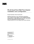
Quick Start Guide
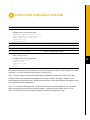
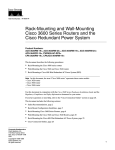
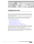
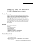
C I S C O MC3810 S E R I E S
MULTISERVICE ACCESS CONCENTRATORS
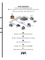
INSTALLATION AND STARTUP
Telephone
network
Digital or
analog PBX
K
E1
T1/
64
r nX
o
Cisco
MC3810
Ethernet
hub
SNA
Computer
Video
codec
Video
1
OBTAIN TOOLS AND EQUIPMENT
2
INSTALL CHASSIS AND CONNECT CABLES
3
GET SITE INFORMATION
4
POWER UP THE CISCO MC3810
5
PERFORM INITIAL CONFIGURATION
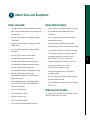
Obtain Tools and Equipment
Items Included
Items Not Included
•
Cisco MC3810 multiservice access concentrator
•
Four screws for installing the chassis in a rack
•
Rack-mount brackets, power cord, and spare set
of rubber feet
•
E1 channel service unit/data service unit
(CSU/DSU)
•
RJ-45-to-DB-9 female DTE adapter (labeled
TERMINAL)
•
PC running terminal emulation software for
administrative access
•
RJ-45-to-DB-25 female DTE adapter (labeled
TERMINAL)
•
Modem for remote administrative access
•
Ethernet cable: RJ-45-to-RJ-45 straight-through
•
RJ-45-to-DB-25 male DCE adapter (labeled
MODEM)
•
T1/E1 cable: RJ-48-to-RJ-48 straight-through
•
RJ-45-to-RJ-45 rollover console cable
•
•
Quick Start Guide (this document)
Cisco synchronous serial transition cable for
connecting a serial port to EIA/TIA-232,
EIA/TIA-449, V.35, X.21, or EIA-530
•
Cisco MC3810 Series Multiservice Access
Concentrators Hardware Installation Guide
•
Digital voice cable: RJ-48-to-RJ-48 rollover
•
Analog voice cables, FXO or FXS:
RJ-11-to-RJ-11 straight-through
•
Analog voice cables, E&M: 8-conductor
straight-through
•
BRI S/T cables: 8-conductor straight-through
and 8-conductor rollover
•
CTR17 adapter for connecting E&M 4-wire per
ETSI CTR17
•
Cisco MC3810 Multiservice Access
Concentrators Software Configuration Guide
•
Cisco MC3810 Multiservice Access
Concentrators Regulatory Compliance and
Safety Information
•
Installing and Removing Field-Replaceable
Units in Cisco MC3810 Series Multiservice
Access Concentrators
•
Cisco IOS release notes
Ordering Information
•
Documentation CD-ROM
•
Product warranty card
To place an order, contact Cisco Customer Service
(408 526 4000 or 800 553 6387).
•
Cisco Information Packet
•
Cisco information wallet card and sticker
1
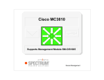
Install Chassis and Connect Cables
Front panel forward
T1/E1
1
2
E&M
3
E&M
E&M
4
5
E&M
6
E&M
FXO
Rear panel forward
T1/E1
1
2
E&M
2
E&M
3
E&M
4
5
E&M
FXO
E&M
6
FXO
FXO
Rear panel forward,
center-mount telco
Safety Information
Warning See the Cisco MC3810 Series
Caution Do not remove the rubber feet.
Multiservice Access Concentrators
Hardware Installation Guide for safety
information you need to know before
working on the Cisco MC3810.
They provide a space for air circulation.
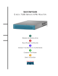
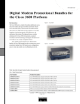
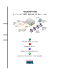
Rack-Mounting the Chassis
Step 1
Desktop Installation
Caution If you place the Cisco MC3810
on a desktop, do not place anything that
weighs more than 10 pounds
(4.5 kilograms) on top of the chassis.
Choose one of the methods shown in the
above figure, and attach the mounting
brackets as shown.
Note: Brackets are included. Screws are included
for attaching the brackets to the chassis, but not for
installing the chassis in a rack. You need four
additional screws to install the chassis in a rack.
Step 2
Install the chassis in the rack.
Install Chassis and Connect Cables (continued)
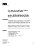
Power supply
and fan at the top
3
Vertical
wall stud
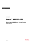
Wall-Mounting the Chassis
Step 1
Install the smaller brackets as shown in
the figure above.
Step 2
Attach the chassis to the wall.
• Position the end nearest the power cable
at the top
• Align screws with a wall stud, or use
wall anchors
Note: Screws for attaching the chassis to a wall are
not included. You need to provide four screws
suitable for your wall installation.
Caution Do not remove the rubber feet.
They provide a space for air circulation.
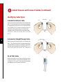
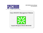
Install Chassis and Connect Cables (continued)
Identifying Cable Types
8-Conductor Rollover Cable
Pin 1
Same color
Pin 8
Hold the connectors side-by-side, with the tab at the
back. The colored wires are in the opposite sequence
at opposite ends of the cable. If your cable came from
Cisco Systems, pin 1 is white on one plug, and pin 8
is white on the opposite plug. (A rollover cable
reverses the wire connections at the opposite ends:
1 to 8, 2 to 7, 3 to 6, 4 to 5, 5 to 4, 6 to 3, 7 to 2, and
8 to 1.)
4
8-Conductor Straight-Through Cable
Same color
Pin 1
Pin 1
Hold the connectors side-by-side, with the tab at the
back. The colored wires are in the same sequence at
opposite ends of the cable. (A straight-through cable
connects like-numbered pins at opposite ends: 1 to 1,
2 to 2, 3 to 3, 4 to 4, 5 to 5, 6 to 6, 7 to 7, and 8 to 8.)
RJ-48 T1/E1 Cable
View the connector for the Cisco MC3810 port, with
the tab at the back. There are wires attached to four
of the pins: 1, 2, 4, and 5. (The pinout at the opposite
end depends on the interface at that end.)
1
5
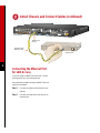
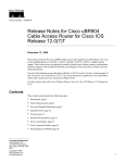
Install Chassis and Connect Cables (continued)
T1/E1
1
E&M
2
E&M
3
E&M
4
55
E&M
E&M
FXO 6
FXO
FXO
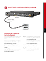
T1/E1 trunk port
(RJ-48 shown)
Cisco MC3810
RJ-48 straight-through cable
or two 75-ohm coaxial
cables with BNC connectors
(not shown)
Network demarcation
(RJ-48 shown)
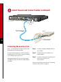
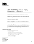
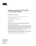
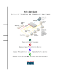
Connecting the T1/E1 Trunk
Port to the Network
If you are using a T1/E1 network interface, connect
the T1/E1 trunk port to a network demarcation
device.
Step 1
If the trunk port has an RJ-48 jack, use an RJ-48
straight-through cable (not included), or a special
cable if required for your application.
If the trunk port has BNC connectors, use two
75-ohm coaxial cables with BNC connectors (not
included).
Note: The T1/E1 trunk port, when present, has a
built-in CSU/DSU for connection to a service
provider’s network interface.
For an RJ-48 cable—Connect one end of
the cable to the RJ-48 jack labeled T1/E1
on a light-green background.
For coaxial cables—Connect one end of
the cables to the BNC connectors labeled
E1 on a light-green background.
Note: Be sure to make the correct transmit and
receive connections for both 75-ohm cables.
Step 2
Connect the other end of the cable(s) to
the network demarcation device (telco
demarc or equivalent).
5
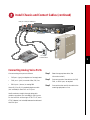
Install Chassis and Connect Cables (continued)
BRI 0 S/T
1
2
3
4
5
T1/E1
6
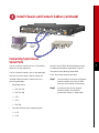
Cisco MC3810
BRI S/T backup port
(CB-1D)
8-conductor
straight-through
cable
NT1
ISDN wall jack
(U interface)
S/T
U
6
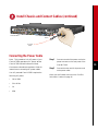
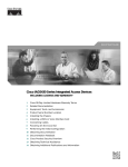
Connecting the BRI S/T Backup
Port to the Network
If your Cisco MC3810 supports BRI S/T backup,
connect the BRI S/T backup port to the ISDN
network.
Use an 8-conductor straight-through cable (not
included).
Step 1
Connect one end of the cable to the port
labeled BRI 0 S/T on an orange
background.
Step 2
Connect the other end of the cable to the
S/T interface of the NT1.
Step 3
If the NT1 is not already connected to the
ISDN network, connect the U interface of
the NT1 to the ISDN wall jack
(U interface).
Note: Step 3 should only be necessary in locations
where the U interface is accessible to the user, such as
in the United States.
Install Chassis and Connect Cables (continued)
T1/E1
1
E&M
2
E&M
3
E&M
4
5
E&M
6
E&M
FXO
FXO
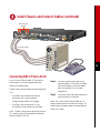
Serial 0
port
Serial 1
port
Cisco serial
transition
cables
Cisco MC3810
CSU/DSU
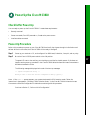
Connecting Synchronous
Serial Ports
You can connect the serial 0 port to a Frame Relay
network or to user equipment.
You can connect the serial 1 port to user equipment.
Use one of the Cisco serial transition cables (not
included). Select the cable to match both of the
following parameters:
•
Note: Both serial ports are dark blue.
Step 1
Connect the 60-pin connector of the serial
transition cable to the Cisco MC3810
serial port to be used for this interface.
Step 2
Connect the other end of the serial
transition cable to the CSU/DSU,
synchronous modem, or video codec.
Signaling protocol:
— EIA/TIA-232
— EIA/TIA-449
— V.35
— X.21
— EIA-530
•
See the Cisco MC3810 Series Multiservice Access
Concentrators Hardware Installation Guide for
information about selecting these cables.
Cisco MC3810 serial port operating mode:
— DTE
— DCE
7
Install Chassis and Connect Cables (continued)
T1/E1
1
E&M
2
E&M
3
E&M
4
5
E&M
6
E&M
FXO
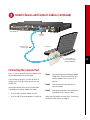
Cisco MC3810
10BaseT port
(RJ-45)
8
Straight-through
Ethernet cable
7
1
Ethernet hub
8
Connecting the Ethernet Port
for LAN Access
If you are using a 10BaseT Ethernet LAN, connect
the Ethernet 0 port to the Ethernet hub.
Use a standard, straight-through, 10BaseT Ethernet
cable (not included).
Step 1
Connect the cable to the Ethernet 0 port
(yellow).
Step 2
Connect the other end of the cable to an
Ethernet hub.
Install Chassis and Connect Cables (continued)
FXS port FXO port E&M port
T1/E1
1
2
3
4
5
6
Cisco MC3810
RJ-11 jack
to central office
PBX
Telephone
Connecting Analog Voice Ports
Connect analog voice ports as follows:
•
FXS port—(gray) to telephone or fax equipment
•
FXO port—(pink) to central office (CO) line
•
E&M port—(brown) to analog PBX
Use an RJ-11-to-RJ-11 standard telephone cable
(not included) for each FXO or FXS port.
Use 8-conductor, straight-through cables with
modular connectors (not included) for E&M ports.
For 4-wire E&M conforming to ETSI CTR17, use a
CTR17 adapter (not included) between the cable and
the E&M port.
Step 1
Select the appropriate cable. (See
information at left.)
Step 2
Connect one end of the cable to the FXS,
FXO, or E&M port, as required.
Step 3
Connect the other end of the cable to the
matching equipment or line.
9
Install Chassis and Connect Cables (continued)
T1
T1/E1
T1/E1
Cisco MC3810
Digital voice port
(RJ-48 shown)
RJ-48-to-RJ-48 rollover cable
or two 75-ohm coaxial
cables with BNC connectors
(not shown)
10
PBX
Connecting the T1/E1 Digital
Voice Port
If your Cisco MC3810 has a T1/E1 digital voice
port, connect it to a digital PBX.
Step 1
If the digital voice port has an RJ-48 jack, use an
RJ-48-to-RJ-48 rollover cable (not included), or a
special cable if required for your application.
If the digital voice port has BNC connectors, use two
75-ohm coaxial cables with BNC connectors (not
included).
Note: For an RJ-48 connection to most PBXs, a
rollover cable is required. However, some PBXs may
have a connector pinout for a straight-through cable.
For an RJ-48 cable—Connect one end of
the cable to the RJ-48 jack labeled T1/E1
on a tan background.
For coaxial cables—Connect one end of
the cables to the BNC connectors labeled
E1 on a tan background.
Note: Be sure to make the correct transmit and
receive connections for both 75-ohm cables.
Step 2
Connect the other end of the cable(s) to
the digital PBX.
Install Chassis and Connect Cables (continued)
BRI voice ports
(CB-1D)
BVM
T1/E1
ALM
B2
B1
ALM
B2
B1
BRI 1
BRI 2
ALM
B2
B1
T1/E1
ALM
B2
B1
BRI 3
BRI 4
Cisco MC3810
8-conductor cables
11
PBX (PINX)
Connecting BRI S/T Voice Ports
If your Cisco MC3810 has BRI S/T voice ports,
connect them to a Private Integrated Services
Network Exchange (PINX).
Step 1
Connect one end of each cable to the
appropriate BRI S/T voice port on the BRI
voice module (BVM). Ports are labeled
BRI 1 through BRI 4 on an orange
background.
Step 2
Connect the other end of each cable to the
appropriate port on the PINX.
The BRI voice ports are wired as terminal equipment
(TE).
•
•
If the PINX ports are wired as network
termination (NT), use 8-conductor
straight-through cables (not included).
If the PINX ports are wired as TE, use
8-conductor rollover cables (not included).
Note: The BRI voice ports are physically wired as
TE. However, they can be software-configured to
function as either TE or NT.
Note: BRI ports on the Cisco MC3810 do not
require external power from the PINX when in TE
mode and do not supply power to external devices
when in NT mode.
Install Chassis and Connect Cables (continued)
T1/E1
Serial port
0 or 1
Cisco MC3810
VDM port
Dialing port Video data port
V.35 DCE
with RI cable
RS-366 cable
26427
Monitor
and camera
Video codec
12
Connecting Video Dialing
Module
If your Cisco MC3810 has a video dialing module
(VDM), connect the VDM port and one of the
Cisco MC3810 serial ports to the video codec.
Step 1
For the dialing interface, use an RS-366 cable with
one 26-pin connector and one DB-25 connector
(included with VDM).
Note: Both serial ports are dark blue.
For the video data connection, use a Cisco V.35 DCE
serial transition cable with ringing indicator (RI)
(included with VDM).
Note: For video conferencing, you must also set up
a WAN connection through the T1/E1 trunk port.
See the “Connecting the T1/E1 Trunk Port to the
Network” section on page 5.
Connect the 60-pin connector of the V.35
serial cable to the Cisco MC3810 serial
port to be used for this interface.
Step 2
Connect the other end of the V.35 serial
cable to the video data port of the video
codec.
Step 3
Connect the 26-pin connector of the
RS-366 cable to the VDM port (dark
blue).
Step 4
Connect the DB-25 connector of the
RS-366 cable to the dialing port of the
video codec.
Install Chassis and Connect Cables (continued)
T1/E1
1
E&M
2
E&M
3
E&M
4
5
E&M
6
E&M
FXO
Cisco MC3810
Console port
(RJ-45)
RJ-45-to-RJ-45
rollover cable
PC (laptop)
RJ-45-to-DB-9 or
RJ-45-to-DB-25 adapter
(labeled TERMINAL)
Connecting the Console Port
Note: If you are going to configure remotely, skip
this procedure and go to the next page.
Step 1
If you are using a local PC or ASCII terminal to
configure your Cisco MC3810, connect it to the
console port.
Connect the appropriate adapter labeled
TERMINAL to the communication port
(usually labeled COM) on your PC or
terminal.
Step 2
Use the light-blue RJ-45-to-RJ-45 rollover cable
(included) and a terminal adapter (included):
Connect one end of the cable to the
terminal adapter.
Step 3
Connect the other end to the console port
(light blue) on the Cisco MC3810.
•
RJ-45-to-DB-9 terminal adapter for a PC
•
RJ-45-to-DB-25 terminal adapter for a terminal
When you are finished, continue to the “Connecting
the Power Cable” section on page 15.
13
Install Chassis and Connect Cables (continued)
AVT
T1/E1
1
E&M
2
E&M
3
E&M
4
5
E&M
E&M
6
FXO
Cisco MC3810
Auxiliary (AUX) port
(RJ-45)
RJ-45-to-RJ-45
rollover cable
Modem
RJ-45-to-DB-25 adapter
(labeled MODEM)
14
Connecting the Auxiliary Port
Note: If you are going to configure locally, follow
the procedure on the previous page.
Step 1
Connect the adapter labeled MODEM to
your modem.
If you are using a remote PC or ASCII terminal to
configure your Cisco MC3810, connect the modem
(not included) to the auxiliary port.
Step 2
Connect one end of the cable to the
modem adapter.
Step 3
Connect the other end of the cable to the
auxiliary port (black) on the
Cisco MC3810.
Use the light-blue RJ-45-to-RJ-45 rollover cable
(included) and an RJ-45-to-DB-25 modem adapter
(included).
When you are finished, continue to the “Connecting
the Power Cable” section on page 15.
Install Chassis and Connect Cables (continued)
T1/E1
1
E&M
2
E&M
3
4
E&M
5
E&M
E&M
6
FXO
Cisco MC3810
Power
switch
To power
outlet
Connecting the Power Cable
Note: This procedure is for AC power. If your
Cisco MC3810 operates on DC power, see the
Cisco MC3810 Series Multiservice Access
Concentrators Hardware Installation Guide for
instructions on connecting DC power cables.
Your AC-powered Cisco MC3810 requires the
following AC power:
•
100 to 240V
•
50 to 60 Hz
•
1A
•
62W
Step 1
Step 2
Connect one end of the power cord to the
power connector on the rear panel of the
Cisco MC3810.
Connect the other end of the power cord
to the power outlet.
When you are finished, continue to the “Get Site
Information” section on page 16.
15
Get Site Information
Get This Information from Your Network Administrator
This table provides space to write down information you need to run the System Configuration Dialog (also
called the setup script).
Item
Ask Your Network Administrator
1
What do you want to name the Cisco MC3810 (to
distinguish it from other Cisco devices on your network)?
2
What should the encrypted enable secret password be?
3
What should the nonencrypted enable password be?
4
What should the password for remote console (Telnet)
access be? This is referred to as the virtual terminal
password (Telnet password).
5
Do you want to configure the Cisco MC3810 for:
SNMP?
— If so, what is the community string?
IP?
16
IGRP routing?
— What is the IGRP autonomous system number?
IPX?
— What are the IPX network numbers?
Bridging?
6
Do you want to configure the modems for:
Default chat script?
Dial-in IP SLIP/PPP access?
Dynamic IP address?
Default IP address?
TCP header compression?
Routing updates on async lines?
Async IPX?
7
Will you be using the Ethernet 0 (10BaseT) interface?
What is the IP address?
How many bits in the subnet mask?
Configure IPX on this interface?
— IPX network number?
Enter the Information in This Column
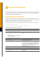
Power Up the Cisco MC3810
Checklist for Power-Up
You are ready to power up the Cisco MC3810 if it meets these requirements:
•
Securely mounted
•
Power connected; Cisco RPS powered on, if used as the power source
•
Interface cables connected
Power-Up Procedure
Perform this procedure to power up your Cisco MC3810 and verify that it goes through its initialization and
self-test. When this is finished, the Cisco MC3810 will be ready to configure.
Step 1
Power up your terminal or PC, and configure it for 9600 baud, 8 data bits, 1 stop bit, and no parity.
Step 2
Move the Cisco MC3810 power switch to the ON position.
The green LED next to the auxiliary port should go on and the fan should operate. If this does not
happen, see the power-up procedure in the Cisco MC3810 Series Multiservice Access Concentrators
Hardware Installation Guide.
The following message is displayed at the end of the boot-up messages.
--- System Configuration Dialog --Would you like to enter the initial configuration dialog? [yes/no]:
Note: If the rommon 1> prompt appears, your system has booted in ROM monitor mode. Follow the
instructions in the appendix, “Booting in ROM Monitor Mode,” in the Cisco MC3810 Multiservice Access
Concentrators Software Configuration Guide before continuing with this procedure.
Continue to Section 5, “Perform Initial Configuration.”
17
Perform Initial Configuration
This section shows how to perform some basic configurations from a local or remote console, using the Cisco
command-line interface. For complete configuration procedures, see the Cisco MC3810 Series Multiservice
Access Concentrators Software Configuration Guide.
Setting the Ethernet Port IP Address
Connect the Ethernet port (yellow) to a live Ethernet connection using a standard Ethernet cable with RJ-45
connectors; then use this procedure to set an IP address for the Ethernet port. After the Ethernet port has an IP
address, you can configure the Cisco MC3810 remotely through a Telnet connection.
The starting point for this procedure is the System Configuration Dialog prompt (shown also on page 16):
--- System Configuration Dialog --Would you like to enter the initial configuration dialog? [yes/no]:
To set the Ethernet port IP address, do the following:
18
Step
Command
Purpose
1
Would you like to enter the initial
configuration dialog? [yes/no]: no
Terminate the System Configuration Dialog.
2
Press Return when you see the following prompt:
Terminate autoinstall and continue setting the Ethernet IP
address.
Would you like to terminate
autoinstall? [yes]:
Several messages are displayed, ending with a line
similar to the following:
flashfs[4]: Initialization complete.
3
Press Return.
Bring up the router> prompt.
4
router> enable
Enable the privileged EXEC mode.
5
router# configure terminal
Enter global configuration mode.
Note The default host name, “router,” appears as part of
the system prompt. To change the host name to another name
such as “europa” that will then appear as the system prompt,
enter hostname europa after Step 5 at the global
configuration prompt—router(config)#.
6
router(config)# enable password password
Set a password for the privileged EXEC mode.
7
router(config)# interface Ethernet 0
Enter the interface configuration mode.
8
router(config-if)# ip address IP-address
subnet-mask
Enter the IP address and subnet mask you want for your
Ethernet port.
Perform Initial Configuration (continued)
Step
Command
Purpose
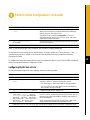
9
router(config-if)# no shutdown
Activate the Ethernet port.
Messages similar to the following appear:
%LINEPROTO-5-UPDOWN: Line protocol on
Interface Ethernet0, changed state to up
%LINK-3-UPDOWN: Interface Ethernet0,
changed state to up
router(config-if)#
10
router(config-if)# exit
Return to global configuration mode.
11
router(config)# line vty 0 4
Enter line configuration mode.
12
router(config-line)# password password
Set a password for remote access to the Cisco MC3810.
13
router(config-line)# end
Return to privileged EXEC mode.
14
router# copy system:running-config
nvram:startup-config
Save the configuration.
Messages similar to the following appear:
Building configuration...
Tablesize is 100
Configure call time
[OK]
router#
Now that the Ethernet port has an IP address, you can either configure the Cisco MC3810 remotely with a Telnet
connection, or you can continue using the console or auxiliary port.
Note: The rest of this quick start guide contains basic configuration instructions for the Cisco MC3810.
However, there are too many possible configurations to discuss in detail in this guide. Therefore, Cisco
recommends that you see the Cisco MC3810 Multiservice Access Concentrators Software Configuration Guide
for all but the most basic configurations.
Note: For voice and video applications, a single master clock source must be established. For information
about configuring synchronized clocking, see the chapter “Configuring Synchronized Clocking” in the
Cisco MC3810 Series Multiservice Access Concentrators Software Configuration Guide.
19
Perform Initial Configuration (continued)
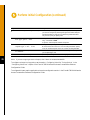
Configuring Basic Settings for Serial Ports 0 and 1
To configure basic settings for serial ports 0 and 1, do the following:
20
Step
Command
Purpose
1
router> show interface serial
Display the default configuration.
2
router> enable
Enable the configuration.
3
router# configuration
Enter configuration mode.
4
router(config)# network-clock
base-rate {56k | 64k}
Configure the network clock base rate setting.
5
router(config)# interface
serial {0 | 1}
Enter serial interface configuration mode.
6
router(config-if)# clock rate
network-clock rate
Configure the serial interface phase-lock-loop clock speed. The range is
300 to 2400 kbps. There is no default.
7
router(config-if)# no shutdown
Activate the serial port.
8
Repeat Steps 5 through 7 to configure the other serial port.
9
router(config-if)# exit
Exit interface configuration mode.
10
router(config)# exit
Exit configuration mode.
11
router> show interfaces serial
Display the serial port configuration to verify the new settings.
Perform Initial Configuration (continued)
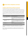
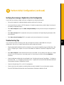
Configuring T1/E1 Controller Settings for T1/E1 Ports
There can be two T1/E1 ports in a Cisco MC3810: a trunk port and a digital voice port.
The T1/E1 trunk port is physically located in the multiflex trunk module (MFT). It supports balanced T1 per
ANSI T1.403, and it supports balanced and unbalanced E1 per ITU G.703. The MFT has a built-in CSU/DSU.
The T1/E1 digital voice port is physically located in the digital voice module (DVM). It supports a balanced T1
interface with a digital PBX, and it supports both balanced and unbalanced E1 interfaces with a digital PBX.
To configure the basic T1/E1 controller settings for T1/E1 ports, do the following for each T1/E1 port that is
present:
Step
Command
Purpose
1
router> configure terminal
Enter global configuration mode.
2
router(config)# controller
{t1 | e1} number
Enter controller configuration mode. Specify whether your controller is
E1 or T1, and enter the controller number. The controller number for a
T1/E1 port in the MFT must be 0. The controller number for a T1/E1
port in the DVM can be 0 (if an MFT is not installed) or 1 (if an MFT
is installed).
3
router(config-ctrl)# clock
source {internal | line |
loop-timed}
Configure the controller clock source for a DS1 link.
4
router(config-ctrl)#
description line
Enter a description of the controller, such as the destination or its
application. The description can be up to 80 characters long.
5
Repeat Steps 2, 3, and 4 for the other T1/E1 port, if it is installed.
If the clock source is a network device attached to the T1/E1 port you
are configuring now, select the line option. For any other clock source
(internal or a network device attached to any other port) select the
internal option.
When you have completed these basic settings, proceed to the appropriate section on the next page:
“Configuring T1 Controller Settings” or “Configuring E1 Controller Settings” and configure the T1 or E1
controller.
Note: For instructions on loopback diagnostics, or for configuring controller channel groups, CAS voice
groups, or TDM cross-connects, see the Cisco MC3810 Series Multiservice Access Concentrators Software
Configuration Guide.
21
Perform Initial Configuration (continued)
Configuring T1 Controller Settings
To configure T1 controller settings, do the following in controller configuration mode:
22
Step
Command
Purpose
1
Configure the cable length setting by doing one of the following:
router(config-ctrl)# cablelength
short {133 | 266 | 399 | 533 |
655}
Configure the cable length if the length is 655 feet or shorter.
router(config-ctrl)# cablelength
long {gain26 | gain36} {-15db |
-22.5db | -7.5db | 0db}
Configure the cable length if the length is longer than 655 feet.
2
router(config-ctrl)# framing
{sf | esf}
Configure the DS1 link framing format. Extended SuperFrame
format (esf) is required for ATM traffic.
3
router(config-ctrl)# linecode
{ami | b8zs}
Configure the line encoding format for the DS1 link. The b8zs setting is
required for ATM traffic.
4
router(config-ctrl)# no shutdown
Activate the T1 controller.
5
router(config-ctrl)# exit
Exit controller configuration mode.
6
router(config)# exit
Exit configuration mode.
7
router> show controller T1 0
Verify the controller configuration.
Configuring E1 Controller Settings
To configure E1 controller settings, perform the following tasks in controller configuration mode:
Step
Command
Purpose
1
router(config-ctrl)# {framing
crc4 | no-crc4} [australia]
Configure the E1 framing format. If the trunk will be connected to a
device in Australia, enter the australia option.
2
router(config-ctrl)# linecode
{ami | hdb3}
Configure the E1 line encoding format. The hdb3 setting is required for
ATM traffic.
3
router(config-ctrl)# no shutdown
Activate the E1 controller.
4
router(config-ctrl)# exit
Exit controller configuration mode.
5
router(config)# exit
Exit configuration mode.
6
router> show controller E1 0
Verify the controller configuration.
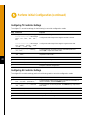
Perform Initial Configuration (continued)
Basic Voice-Port Configuration
This section has separate procedures for analog, digital, and ISDN BRI voice ports. Use the analog procedure to
configure voice ports on the analog voice module (AVM). Use the digital procedure to configure voice ports on
a T1 or E1 line on a digital voice module (DVM) or multiflex trunk module (MFT). Use the BRI procedure to
configure voice ports on the BRI voice module (BVM).
Verifying Voice-Port Configuration
Before entering voice-port configuration mode, enter:
router> show voice port summary
This command brings up a list of the existing voice ports with their slot/port numbers, signaling types, and
status.
Note: An analog voice port exists for each analog personality module (APM) installed in an AVM. ISDN BRI
voice ports exist if a BVM is installed. Digital voice ports do not exist unless you have created one or more voice
groups.
To see the complete current configuration of an existing voice port, enter the following command:
router> show voice port slot/port
The following table summarizes the physical and logical characteristics of the Cisco MC3810 voice ports:
Voice Interface Type
Hardware
Module
Analog
Voice-Port Identification
Slot Number
Port Numbers
AVM
1
1–6
BRI
BVM
1–4
1–2
Digital:
MFT
0
1–24 (for T1)
To network (WAN)
Digital:
To PBX or local phone device
1–15 and 17–31 (for E1)
DVM
1
1–24 (for T1)
1–15 and 17–31 (for E1)
Note: Unlike serial port interfaces and interfaces on other Cisco products, the number 0 is not used to designate
a voice port. Slot/port designations 0/0 and 1/0 are not valid; 0/1 and 1/1 are valid.
23
Perform Initial Configuration (continued)
Configuring Analog Voice Ports
To configure the basic analog voice-port settings, perform the following tasks:
Step
Command
Purpose
1
router> configure terminal
Enter global configuration mode.
2
router(config)# voice-port slot/port
Enter voice-port configuration mode, and specify the voice port
you want to configure by entering the logical slot number and port
number (see table on page 23). The commands entered in Steps 3
through 4 affect only the voice port you specify here.
The slot number for analog voice ports on the Cisco MC3810 is
always 1. The number 0 is not used for any voice port.
3
router(config-voiceport)# codec
{g729r8 | g729ar8 | g726r32 |
g711alaw | g711ulaw}
(Optional) Configure the voice-port compression mode. The
g729ar8 value is the default and is recommended.
Simultaneously active on-net voice call support by compression
mode:
• g729ar8—24 calls maximum
• g729r8—12 calls maximum
24
Nominal data rates for compression modes:
• g729r8 and g729ar8—8 kbps
• g726r32—32 kbps
• g711alaw and g711ulaw—64 kbps
4
router(config-voiceport)# connection
{tie-line | plar | plar opx} string
Configure the voice-port connection mode type. If the connection
is to a PBX, use the tie-line option, If the connection is for Private
Line Auto Ringdown (PLAR) use the plar option.
If the connection is for PLAR Off-Premises eXtension (OPX), use
the plar-opx option. With this option, the local voice port will
provide a local response before the remote voice port receives an
answer, and FXO interfaces will not answer until the remote side
answers.
5
6
If you want to change the default signaling type for the voice port, choose one of the following:
router(config-voiceport)# signal
{loop-start | ground-start}
Configure the signaling type for FXO and FXS voice ports. The
default is loop-start.
router(config-voiceport)# signal
{wink-start | immediate |
delay-dial}
Configure the signaling type for E&M voice ports. The default is
wink-start.
router(config-voiceport)# dial-type
{pulse | dtmf}
Change the transmit dial type if necessary (FXO and E&M ports
only). The default is dtmf.
Only FXO and FXS ports transmit dial pulses.
Perform Initial Configuration (continued)
Step
Command
Purpose
7
router(config-voiceport)# cptone
country
Configure the voice port for the local territory’s call progress tone
setting. The call progress tone setting determines the settings for
dialtone, busytone, and ringback tone.
The default for this command is northamerica. For a list of
supported countries, see the Cisco IOS Voice, Video, and Home
Applications Command Reference.
8
router(config-voiceport)#
no shutdown
9
Exit from voice-port configuration mode and repeat Steps 2 through 8 for the remaining analog voice ports.
Activate the voice port. You should activate only those voice ports
you are planning to use.
Note: If you are not going to use a voice port, shut it down to conserve bandwidth.
To configure voice-port tuning options, see the section “Configuring Voice-Port Tuning Options” in the
“Configuring Voice Ports” chapter of the Cisco MC3810 Multiservice Access Concentrators Software
Configuration Guide.
To configure dial peers, see the applicable voice service configuration section in the Cisco MC3810 Multiservice
Access Concentrators Software Configuration Guide.
Configuring Digital Voice Ports
To configure the basic digital voice-port settings, perform the following tasks:
Step
Command
Purpose
1
router> configure terminal
Enter global configuration mode.
2
router(config)# controller {t1 | e1}
number
Enter controller configuration mode. Specify whether your
controller is E1 or T1, and enter the controller number:
• 0 for voice ports on T1/E1 WAN interface (through the MFT)
• 1 for voice ports on the T1/E1 interface to the local telephone
device or PBX (through the DVM)
3
router(config-controller)# mode cas
Configure the T1/E1 line to support CAS.
4
router(config-controller-cas)#
voice-group channel-no timeslots
timeslot-list type {e&m-immediate |
e&m-delay | e&m-wink | e&m-melcas |
fxs-ground-start | fxs-loop-start |
fxs-melcas | fxo-ground-start |
fxo-loop-start | fxo-melcas}
Configure a list of timeslots to form a CAS group for the T1/E1
line. The “melcas” options are supported only on E1 and apply to
the Mercury Exchange Limited (MEL) standard, used primarily in
the United Kingdom.
5
When configuring a CAS group for a T1/E1 line to a PBX, make
sure that the channel numbers match the PBX channels.
Repeat Step 3 or 4 for each CAS group. After CAS groups are defined, exit CAS controller configuration mode.
25
Perform Initial Configuration (continued)
Step
Command
Purpose
6
router(config)# voice-port slot/port
Enter voice-port configuration mode, and specify the voice port
you want to configure by entering the logical slot number and port
number (see table on page 23). The following commands affect
only the voice port you specify here.
7
router(config-voiceport)#
dial-type {pulse | dtmf}
Change the transmit dial type if necessary (FXO and E&M ports
only). The default is dtmf.
Only FXO and FXS ports transmit dial pulses.
26
8
router(config-voiceport)#
compand-type {u-law | a-law}
Change the companding if necessary. The default is u-law (the
North American mu-law ITU-T PCM encoding standard). Specify
a-law to use the European a-law ITU-T PCM encoding standard.
9
router(config-voiceport)#
no shutdown
Activate the voice port. You should activate only those voice ports
you are planning to use.
10
Exit from voice-port configuration mode and repeat Steps 6 through 9 for the remaining digital voice ports.
Note: If you are not going to use a voice port, shut it down to conserve bandwidth.
To configure voice-port tuning options, see the section “Configuring Voice-Port Tuning Options” in the
“Configuring Voice Ports” chapter of the Cisco MC3810 Multiservice Access Concentrators Software
Configuration Guide.
To configure dial peers, see the applicable voice service configuration section in the Cisco MC3810 Multiservice
Access Concentrators Software Configuration Guide.
Perform Initial Configuration (continued)
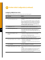
Verifying Your Analog or Digital Voice-Port Configuration
You can test your analog or digital voice-port configuration by doing the following:
•
Pick up the handset of an attached telephony device and check for dial tone.
•
If you have dial tone, check for DTMF detection. If the dial tone stops when you dial a digit, the voice port
is probably configured properly.
•
Enter show voice port slot/port and show voice port summary to verify that the voice-port configuration is
correct.
•
Enter show voice dsp EXEC command to verify the current status of all Digital Signaling Processor (DSP)
voice channels.
•
Enter show voice call summary EXEC command to verify the call status for all voice ports.
Troubleshooting Tips
If you are having trouble connecting a call and you suspect the problem is associated with voice-port
configuration, you can try to resolve the problem by performing the following:
•
Ping the associated IP address to confirm connectivity. If you cannot successfully ping your destination, refer
to the “Configuring IP” chapter in the Cisco IOS Release 12.0 Network Protocols Configuration Guide,
Part 1.
•
Enter show voice port to make sure that the voice port is enabled. You can display information for a single
voice port, for all voice ports, or a summary report. If the voice port is offline, use the no shutdown
command.
•
Check the dial-peer configuration (as configured in the “Configuring Voice over Frame Relay,” “Configuring
Voice over ATM,” or “Configuring Voice over HDLC” chapters of the Cisco MC3810 Multiservice Access
Concentrators Software Configuration Guide).
•
Check the Frame Relay, ATM, or HDLC configuration.
•
Check to see if the voice network module has been correctly installed. For more information, see the
Cisco MC3810 Series Multiservice Access Concentrators Hardware Installation Guide.
27
Perform Initial Configuration (continued)
Configuring ISDN BRI Voice Ports
To configure the basic ISDN BRI voice-port settings, perform the following tasks:
Step
Command
Purpose
1
router> configure terminal
Enter global configuration mode.
2
router(config)#
isdn switch-type basic-qsig
Configure the global ISDN switch type as basic-qsig for the BRI
voice ports.
Note You can configure the ISDN switch type in either global or
interface configuration mode. If you configure it here in Step 2, it
specifies the switch type for all four BVM ports. If you configure it
in Step 4, it specifies the switch type for a single interface. The
switch type specified in Step 4 for any individual interface will
override the globally specified switch type.
3
router(config)#
interface bri number
Enter interface configuration mode to configure parameters for the
specified BRI voice port. The number can be from 1 to 4.
4
router(config-interface bri 1)#
isdn switch-type basic-qsig
If the service provider switch type for this BRI port is different
from the global ISDN switch type, configure the interface ISDN
switch type to match the service provider switch type. The
interface ISDN switch type overrides the global ISDN switch type
on this interface.
5
router(config-interface bri 1)#
isdn protocol-emulate {user |
network}
Configure the Layer 2 and Layer 3 port protocol emulation:
28
• Enter user to configure the port as TE. This is the default.
• Enter network to configure the port as NT.
Note The term user is equivalent to the QSIG term slave. The
term network is equivalent to the QSIG term master.
6
router(config-interface bri 1)#
isdn layer1-emulate {user | network}
Configure the Layer 1 port mode emulation and the clock settings:
• Enter user to configure the port as TE and to function as a
clock slave. This is the default.
• Enter network to configure the port as NT and to function as a
clock master.
7
router(config-interface bri 1)#
[no] line-power
Turn on or off the power supplied from an NT-configured port to
a TE device. The default is no line-power.
8
router(config-interface bri 1)#
network-clock-priority {low | high}
If this BRI voice port is configured as TE, and you want it to act as
a clock slave and recover clock from the network NT device, set it
to high.
If this BRI voice port is configured as TE, and you do not want it
to recover clock from the network NT device, set it to low.
This command is not used if this port is configured as NT with the
command isdn layer1-emulate network.
Perform Initial Configuration (continued)
Step
Command
Purpose
9
router(config-interface bri 1)#
isdn overlap-receiving
Activate overlap signaling to the destination PBX.
10
router(config-interface bri 1)#
isdn network-failure-cause
cause code
Specify the cause code to pass to the PBX when a call cannot be
placed or completed because of internal network failures. Possible
values are from 1 to 127.
29
Corporate Headquarters
Cisco Systems, Inc.
170 West Tasman Drive
San Jose, CA 95134-1706
USA
http://www.cisco.com
Tel: 408 526-4000
800 553-NETS (6387)
Fax: 408 526-4100
European Headquarters
Cisco Systems Europe s.a.r.l.
Parc Evolic, Batiment L1/L2
16 Avenue du Quebec
Villebon, BP 706
91961 Courtaboeuf Cedex
France
http://www-europe.cisco.com
Tel: 33 1 69 18 61 00
Fax: 33 1 69 28 83 26
Americas
Headquarters
Cisco Systems, Inc.
170 West Tasman Drive
San Jose, CA 95134-1706
USA
http://www.cisco.com
Tel: 408 526-7660
Fax: 408 527-0883
Asia Headquarters
Nihon Cisco Systems K.K.
Fuji Building, 9th floor
3-2-3 Marunouchi
Chiyoda-ku, Tokyo 100
Japan
http://www.cisco.com
Tel: 81 3 5219 6250
Fax: 81 3 5219 6001
Cisco Systems has more than 200 offices in the following countries. Addresses, phone numbers, and fax numbers are listed on the
C i s c o C o n n e c t i o n O n l i n e We b s i t e a t h t t p : / / w w w. c i s c o . c o m / o f fi c e s .
Argentina • Australia • Austria • Belgium • Brazil • Canada • Chile • China • Colombia • Costa Rica • Croatia • Czech Republic • Denmark • Dubai, UAE
Finland • France • Germany • Greece • Hong Kong • Hungary • India • Indonesia • Ireland • Israel • Italy • Japan • Korea • Luxembourg • Malaysia
Mexico • The Netherlands • New Zealand • Norway • Peru • Philippines • Poland • Portugal • Puerto Rico • Romania • Russia • Saudi Arabia • Singapore
Slovakia • Slovenia • South Africa • Spain • Sweden • Switzerland • Taiwan • Thailand • Turkey • Ukraine • United Kingdom • United States •
Venezuela
Copyright © 1999, Cisco Systems, Inc. All rights reserved. Access Registrar, AccessPath, Any to Any, AtmDirector, CCDA, CCDE, CCDP, CCIE, CCNA, CCNP, CCSI, CD-PAC, the Cisco logo, Cisco Certified
Internetwork Expert logo, CiscoLink, the Cisco Management Connection logo, the Cisco NetWorks logo, the Cisco Powered Network logo, Cisco Systems Capital, the Cisco Systems Capital logo, Cisco Systems
Networking Academy, the Cisco Technologies logo, ConnectWay, ControlStream, Fast Step, FireRunner, GigaStack, IGX, JumpStart, Kernel Proxy, MGX, Natural Network Viewer, NetSonar, Network Registrar,
New World, Packet, PIX, Point and Click Internetworking, Policy Builder, Precept, RouteStream, Secure Script, ServiceWay, SlideCast, SMARTnet, StreamView, The Cell, TrafficDirector, TransPath, ViewRunner,
VirtualStream, VisionWay, VlanDirector, Workgroup Director, and Workgroup Stack are trademarks; Changing the Way We Work, Live, Play, and Learn, Empowering the Internet Generation, The Internet
Economy, and The New Internet Economy are service marks; and Asist, BPX, Catalyst, Cisco, Cisco IOS, the Cisco IOS logo, Cisco Systems, the Cisco Systems logo, the Cisco Systems Cisco Press logo,
Enterprise/Solver, EtherChannel, EtherSwitch, FastHub, FastLink, FastPAD, FastSwitch, IOS, IP/TV, IPX, LightStream, LightSwitch, MICA, NetRanger, Registrar, StrataView Plus, Stratm, TeleRouter, and VCO are
registered trademarks of Cisco Systems, Inc. in the U.S. and certain other countries. All other trademarks mentioned in this document are the property of their respective owners. The use of the word partner does
not imply a partnership relationship between Cisco and any of its resellers. (9906R)
Printed in the USA on recycled paper containing 10% postconsumer waste.
DOC-MC3810-QSG=
78-4879-05