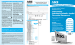
1
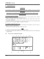
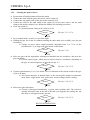
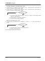
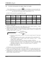
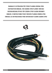
CEBORA S.p.A.
1
SPOT 3500
POWER SOURCE art. 2150
SERVICE MANUAL
3.302.047
21/12/00
CEBORA S.p.A.
2
CONTENTS
1
- GENERAL INFORMATION
- Introduction.
- General service policy.
- Safety information.
- Electromagnetic compatibility.
- SYSTEM DESCRIPTION
2.1
- Introduction.
2.2
- Technical specifications.
2.3
- Description of power source art. 2150.
- MAINTENANCE
3.1
- Periodic inspection, cleaning.
3.2
- Sequence of operations (fig. 3.2.1).
3.2.1
- Power source commands and signals.
3.2.2
- Starting the power source.
3.3
- Troubleshooting.
3.3.1
- The power source does not start, lamp (6) off.
3.3.2
- Power source powered, the start button produces no effect (temperature check).
3.3.3
- In open circuit operation, the output voltage is not regular.
3.3.4
- In resistive load operation, the output voltage is not regular.
3.3.5
- In actual working conditions (thus with high currents), the welding quality is not satisfactory.
- COMPONENTS LIST
4.1
- Power source art. 2150 : see file ESP2150.pdf enclosed at the end of the manual.
4.2
- Components table: see file ESP2150.pdf enclosed at the end of the manual.
4.3
- Spare parts list.
- ELECTRICAL DIAGRAMS
5.1
- Power source art. 2150: see file SCHE2150.pdf enclosed at the end of the manual.
5.2
- Waveforms.
5.2.1
- Output voltage, static switch (14) upon engagement (par. 3.3.1).
5.2.2
- Minimum output voltage, manual mode (par. 3.3.3, 3.3.4).
5.2.3
- Maximum output voltage, manual mode (par. 3.3.3, 3.3.4).
5.2.4
- Output voltage, pulse train mode (par. 3.3.3, 3.3.4).
5.2.5
- Output voltage, single stroke mode (par. 3.3.3, 3.3.4).
5.2.6
- “Current presence” signal of the current transducer (28) (par. 3.3.4, 3.3.5).
5.3
- Control board (27) code 5.600.857.
1.1
1.2
1.3
1.4
2
3
4
5
3.302.047
21/12/00
3
3
3
3
3
4
4
4
4
6
6
6
6
7
8
8
10
11
12
14
15
15
15
15
16
16
16
16
16
16
17
17
17
18
CEBORA S.p.A.
3
1 - GENERAL INFORMATION
1.1 - Introduction.
The purpose of this manual is to train personnel assigned to carry out maintenance on the
power source art. 2150 for auto body welding and spot-welding systems.
1.2 - General service policy.
It is the responsibility of the customer and/or operator to use the equipment appropriately, in
accordance with the instructions in the Manual, as well as to maintain the equipment and related
accessories in good working condition, in compliance with the instructions provided in the
Service Manual.
Any internal inspection or repairs must be carried out by qualified personnel who are
responsible for any intervention on the equipment.
It is forbidden to attempt to repair damaged electronic boards or modules; replace them with
original Cebora spare parts.
1.3 - Safety information.
The safety notes provided in this manual are an integral part of those given in the Instruction
Manual. Therefore, before working on the machine, please read the paragraph on safety
instructions in the aforementioned manual.
Always disconnect the power cord from the mains before accessing the interior of the
equipment.
Some internal parts, such as terminals and dissipaters, may be connected to mains or
otherwise hazardous potentials. It is therefore forbidden to work with the safety guards removed
from the machine unless strictly necessary. In this case, take special precautions such as wearing
insulating gloves and footwear, and working in a perfectly dry environment with dry clothing.
1.4 - Electromagnetic compatibility.
Please read and observe the instructions provided in the paragraph “Electromagnetic
compatibility” of the Instruction Manual.
3.302.047
21/12/00
CEBORA S.p.A.
4
2 - SYSTEM DESCRIPTION
2.1 - Introduction.
The SPOT 3500 is a multi-function system for welding, spot-welding, warming and rectifying
auto body metal.
It is made up of an electronic power source (art. 2150), and a set of accessories to adapt to
various applications and tasks (see list in Sales Catalogue).
The power source is controlled by electronic circuits, which manage its user interface and the
operation in the various tasks.
2.2 - Technical specifications.
To verify the technical specifications, see the machine plate, Instruction Manual, and Sales
Catalogue.
2.3 - Description of power source art. 2150.
Art. 2150 is an alternating voltage power source made up of a single-phase transformer and a
scr static switch, capable of partializing the mains supply voltage to adjust the output current.
Reference to fig. 3.2.1, the electrical diagram in par. 5.1, drawing 4.1 and table 4.2, we can
identify the main blocks that make up the power source.
The control board (27) is powered directly through the main switch (5), and also the power
transformer (26) through the switch static (14).
The control board (27) contains both the power supply circuits and those to adjust the output
current, and generates the pulses to drive the scr static switch (14) based on the incoming signals
from the switches and potentiometers on the front panel. The latter regulates the supply voltage
to the primary circuit of the transformer (26), whose secondary circuit is directly connected to
the power source output.
On the secondary circuit of the transformer (26) is a Hall-effect current sensor, which
provides the control board (27) with the current presence signal at the power source output. It is
calibrated to provide the “current present” signal when the output current exceeds approximately
100 Aac (it does not indicate the current value, but merely whether it is greater than or less than
approximately 100 Aac).
The start signal to the power source is provided by the button on the gun trigger, connected to
the control board (27) by the connector (10).
The gun also has a thermostat, also connected to the control board (27) via the connector (10),
which blocks operation of the power source in case of gun overtemperature, or with the
connector (10) disconnected. These situations are indicated upon start-up by the red led (4) on
the front panel.
To carry out the above procedures, three operating modes are available; you may select
among them using the switches (1) and (11) on the front panel:
− automatic single stroke, recommended for spot-welding;
− automatic pulse train, recommended for mending;
− manual, recommended for warming and rectifying.
In the first instance, the power source delivers the maximum output voltage for a time,
adjustable via potentiometer (2) on the front panel, which begins by starting to circulate current,
thus after both pressing the start button and after the electrode has come into contact with the
sheet metal. Once this time has elapsed, voltage is no longer output until the start button is
pressed again.
In the second instance, the power source behaves as in the previous case, with the difference
that once the output time has elapsed, there is a pause of approximately 400 msec. (fixed time)
without output voltage, after which output voltage is once again generated for a duration equal to
3.302.047
21/12/00
CEBORA S.p.A.
5
the previous time, before the pause. This generating cycle is automatically repeated as long as
the start button is held down.
In the third instance, the power source delivers an output voltage adjustable via potentiometer
(3) on the front panel, without any time limit, for as long as the start button is held down. In this
case the output voltage is adjusted by partializing the waveform of the mains voltage applied to
the primary circuit of the transformer (26).
In all 3 cases, after the start button is pressed, the static switch (14) begins conducting in
synchrony with the mains voltage, thus it engages simultaneously with the maximum peak of the
sine wave of the supply voltage (see fig. 5.2.1), to avoid saturating the transformer (26).
For the same reason, the output time in automatic mode is determined by counting a number
of half cycles of the mains voltage, always even and complete, and current delivery always ends
with the half cycle opposite the one first used for output.
The signals processed by the electronic board and present at its connectors are listed in the
table in chapter five of this manual.
3.302.047
21/12/00
CEBORA S.p.A.
6
3 - MAINTENANCE
WARNINGS
ANY INTERNAL INSPECTIONS OR REPAIRS MUST BE CARRIED OUT BY QUALIFIED
PERSONNEL.
DISCONNECT THE POWER SOURCE FROM THE MAINS BEFORE PERFORMING
MAINTENANCE.
3.1 - Periodic inspection, cleaning.
Periodically remove any dirt or dust from the air vents to ensure smooth air flow, and thus
adequate cooling of the internal parts of the power source.
Check the condition of the output terminals, output and power supply cables of the power
source; replace if damaged.
Check the condition of the internal power connections and connectors on the electronic board;
if you find “loose” connections, tighten or replace the connectors.
3.2 - Sequence of operations (fig. 3.2.1).
The following sequence represents correct functioning of the machine. It may be used as a
guiding procedure for troubleshooting.
It must be carried out after each repair without any errors.
NOTE
q Operations preceded by this symbol refer to operator actions.
♦ Operations preceded by this symbol refer to machine responses that must occur following an
operator action.
3.2.1
3.302.047
- Power source commands and signals.
21/12/00
CEBORA S.p.A.
3.2.2
q
q
q
q
q
7
- Starting the power source.
System shut off and disconnected from the mains.
Connect the cable with the gun at the power source output (9).
Connect the start signal cable of the gun to the connector (10).
Connect the cable to the earth clamp at the output (8) of the power source, and the earth
clamp to the metal workpiece (see Instruction Manual for fastening procedure).
Close the switch (5).
♦ System powered, lamp (6) lit, red led (4) off.
Correct?
q
q
YES
Set to manual mode, switch (1) lever to the right.
Holding the gun free in the air (without touching the sheet metal to be welded), press the gun
start button.
♦ Voltage on power source output terminals, adjustable from 2 to 7 Vac via the
potentiometer (3), as long as the start button is held down.
Correct?
q
NO (see 3.3.4-3.3.5).
YES
Turn the potentiometer (2) or (3) to obtain a level or duration of the current suited to the type
of job to be done.
♦ The current intensity, in manual mode, or the current pulse duration in automatic
mode (both “single stroke” and “pulse train” modes) changes while working.
Correct?
q
NO (see 3.3.3).
YES
Move the gun with the appropriate working tool attached near the workpiece, and press the
gun start button.
♦ Current output begins, which may be pulsed, timed or continuous, depending on
the type of work being done, as described in par. 2.3.
Correct?
q
NO (see 3.3.1-3.3.2).
NO (see 3.3.4-3.3.5).
YES
Release the gun start button.
♦ Current is interrupted immediately, or pulse train repetition ends. The current is
actually interrupted only at the end of the half cycle opposite the starting one, but
this delay is not apparent to the operator.
Correct?
NO (see 3.3.4-3.3.5).
YES
REGULAR OPERATION.
3.302.047
21/12/00
CEBORA S.p.A.
8
3.3 - Troubleshooting.
WARNINGS
ANY INTERNAL INSPECTIONS OR REPAIRS MUST BE CARRIED OUT BY QUALIFIED
PERSONNEL.
BEFORE REMOVING THE PROTECTIVE GUARDS AND ACCESSING INTERNAL
PARTS, DISCONNECT THE POWER SOURCE FROM THE MAINS.
NOTE
Items in boldface describe problems that may occur on the machine (symptoms).
q Operations preceded by this symbol refer to situations the operator must determine (causes).
♦ Operations preceded by this symbol refer to actions the operator must perform in order to
solve the problems (solutions).
3.3.1
q
- The power source does not start, lamp (6) off.
MAINS SUITABILITY TEST.
No voltage for mains protection.
NO
♦
♦
♦
♦
♦
♦
♦
3.302.047
Correct?
YES
Eliminate any short-circuits on the connections between power cable, switch (5),
transformer (26) and static switch (14).
Check the wiring between terminals 8 - 9, 11 - 12 of CN4 on the control board
(27) and static switch (14).
Make sure that the static switch (14) is not short-circuited. Replace if necessary.
Make sure the windings of the transformer (26) are isolated from one another and
from earth. If insulation leaks, replace the transformer (26).
Make sure that the static switch (14) is properly engaged. For this test, insert the
oscilloscope (with memory if possible) on the power source output terminals, set
the power source to automatic mode, switch lever (11) to the left, and press the
gun start button while holding it free in the air (open circuit operation). In this
condition, the static switch (14) must be engaged simultaneously with the peak of
the sine curve of the mains voltage (fig. 5.2.1), thus approximately 90° - 100°
before it crosses 0. If necessary, set the trimmer RV2 on the control board (27).
More accurate adjustment is possible by measuring the current at the primary
circuit of the transformer (26), using a TA and oscilloscope, and adjusting the
trimmer RV2 until the first current peak is as high as subsequent peaks. For this
test, we recommend making several attempts, moving the trimmer RV2 each time
to seek out the ideal position.
Replace control board (27).
Mains not suitable to power the power source (ex.: insufficient installed power).
21/12/00
CEBORA S.p.A.
q
q
9
CONTROL BOARD (27) POWER SUPPLY TEST.
Control board (27), connector CN4, terminals 1 and 5 = 380/415/440 Vac, with switch (5)
closed, for machines with this supply voltage.
Control board (27), connector CN4, terminals 3 and 5 = 220/230/240 Vac, with switch (5)
closed, for machines with this supply voltage.
YES
Correct?
NO
♦ Check the wiring between terminals 1 and 5 (or 3 and 5) of CN4 on the control
board (27) and switch (5).
♦ Check switch (5), and replace if defective.
♦ Check the mains voltage conditions.
q
SERVICES POWER SUPPLY TEST.
Control board (27), connector CN3, terminals 4 (+) and 6 (-) = +12 Vdc, with switch (5)
closed.
YES
Correct?
NO
♦ Check the status of fuse F1 on control board (27).
♦ Replace control board (27).
♦ Power supply regular, replace lamp (6).
3.302.047
21/12/00
CEBORA S.p.A.
10
3.3.2 - Power source powered, the start button produces no effect (temperature check).
q
GUN THERMOSTAT TEST.
Control board (27), connector CN1, terminals 2 (+) and 4 (-) = 0 Vdc, contact closed, led (4)
off, with appropriate temperature (approximately +17 Vdc, contact open, led (4) lit, with
temperature beyond limits, or connector (10) disconnected).
YES
♦
♦
♦
♦
q
Correct?
NO
Check the wiring between terminals 2 - 4 of CN1 on control board (27), connector
(10) and gun thermostat.
Check the conditions and operation of the gun thermostat and the connector (10).
If defective, replace.
See CONTROL BOARD (27) POWER SUPPLY TEST and SERVICES POWER
SUPPLY TEST, par. 3.3.1.
Replace control board (27).
START COMMAND TEST.
Control board (27), connector CN1, terminals 2 (+) and 1 (-) = 0 Vdc, with start button
pressed (approximately +17 Vdc with button released or connector (10) disconnected).
YES
Correct?
NO
♦ Check the wiring between terminals 1 - 2 of CN1 on control board (27), connector
(10) and the gun button.
♦ Check the conditions and operation of the gun button and the connector (10). If
defective, replace.
♦ See CONTROL BOARD (27) POWER SUPPLY TEST and SERVICES POWER
SUPPLY TEST, par. 3.3.1.
♦ Replace control board (27).
♦ Replace control board (27).
3.302.047
21/12/00
CEBORA S.p.A.
3.3.3
11
- In open circuit operation, the output voltage is not regular.
OPEN CIRCUIT OUTPUT VOLTAGE TEST IN MANUAL MODE.
Potentiometer (3)
position
at minimum
at maximum
q
q
Output voltage
Vac
2
7
Waveform
Fig. 5.2.2
Fig. 5.2.3
Switch (1) in manual mode (lever to the right), power source output terminals = voltage
values and waveforms as in the table, with start button pressed.
Holding down the start button, turn the potentiometer (3) and make sure the line of the output
voltage waveform changes in a linear, non-abrupt fashion, between the minimum and
maximum values of fig. 5.2.2 and 5.2.3.
YES
♦
♦
♦
♦
♦
Correct?
NO
Check the wiring between CN4 control board (27) and static switch (14).
Check the wiring between the switch (1) and connector CN3 on board (27):
CN3, terminals 1 and 2 = 0 ohm (contact closed), terminals 3 and 4 = > kohm
(contact open) = manual mode. If incorrect, check the status of the switch (1) and
replace if defective.
Check the connections between the secondary transformer circuit (26) and output
terminals of the power source. If you find loose or burnt connections, clean
thoroughly and tighten, or replace any damaged terminals or components.
Replace static switch (14).
Replace control board (27).
NOTE
Timed operation is not possible in the following test, as timing begins only when the output
current exceeds approximately 100 Aac.
q
OPEN CIRCUIT OUTPUT VOLTAGE TEST IN AUTOMATIC MODE.
Switch (1) in automatic mode (lever to the left), power source output terminals = 7 Vac and
waveform per fig. 5.2.3, with start button pressed, regardless of the position of the
potentiometers (2) and (3) and the switch (11).
YES
Correct?
NO
♦ Check the wiring between CN4 control board (27) and static switch (14).
♦ Check the wiring between the switch (1) and connector CN3 on board (27):
CN3, terminals 1 and 2 = > kohm (contact open), terminals 3 and 4 = 0 ohm
(contact closed) = automatic mode. If incorrect, check the status of the switch (1)
and replace if defective.
♦ Check the connections between the secondary transformer circuit (26) and output
terminals of the power source. If you find loose or burnt connections, clean
thoroughly and tighten, or replace any damaged terminals or components.
♦ Replace static switch (14).
♦ Replace control board (27).
♦ Correct operation.
3.302.047
21/12/00
CEBORA S.p.A.
3.3.4
12
- In resistive load operation, the output voltage is not regular.
NOTE
For the following tests use a resistive load capable of circulating a current greater than 100
Aac, for example 0.02 ohm, and capable of supporting the consequent current, considering that
the rated open-circuit output voltage is approximately 7 Vac.
OUTPUT VOLTAGE TEST ON RESISTIVE LOAD.
Type of
operation
manual
manual
automatic,
pulse train
automatic,
single stroke
automatic
q
q
Switch
lever (1)
position
Right
Right
Left
Switch
lever (11)
position
down
Left
up
at maximum
-
-
fig. 5.2.5
Left
-
at minimum
-
-
fig. 5.2.6
♦
♦
♦
♦
♦
q
Waveform
fig. 5.2.2
fig. 5.2.3
fig. 5.2.4
MANUAL MODE TEST.
Switch (1) in manual mode (lever to the right), power source output terminals = voltage
values and waveforms as in the table, with start button pressed.
Holding down the start button, turn the potentiometer (3) and make sure the line of the output
voltage waveform changes in a linear, non-abrupt fashion, between the minimum and
maximum values of fig. 5.2.2 and 5.2.3.
YES
q
Potentiometer Potentiometer Output
(2) position
(3) position
voltage
Vac
at minimum
2
at maximum
7
at minimum
-
Correct?
NO
Check the wiring between connector CN4 on the control board (27) and static
switch (14).
Check the wiring between the switch (1) and connector CN3, control board (27):
CN3, terminals 1 and 2 = 0 ohm (contact closed), terminals 3 and 4 = > kohm
(contact open) = manual mode.
If incorrect, check the status of the switch (1) and replace if defective.
Check the connections between the secondary transformer circuit (26) and output
terminals of the power source. If you find loose or burnt connections, clean
thoroughly and tighten, or replace any damaged terminals or components.
Replace static switch (14).
Replace control board (27).
AUTOMATIC PULSE TRAIN OPERATING MODE TEST.
Switch (1) in automatic mode (lever to the left), switch (11) in pulse train mode (lever
down), power source output terminals = waveform as in fig. 5.2.4, with start button pressed.
Holding down the start button, turn the potentiometer (2) and make sure the pulse packet
length changes to the maximum duration of 1 second per packet (the pause between the pulse
packets remains constant, 400 msec.).
3.302.047
21/12/00
CEBORA S.p.A.
q
q
13
AUTOMATIC SINGLE STROKE OPERATING MODE TEST.
Switch (1) in automatic mode (lever to the left), switch (11) in single stroke mode (lever up),
power source output terminals = waveform as in fig. 5.2.5, each time the start button is
pressed.
Press the start button several times, turning the potentiometer (2) to a different position each
time, and make sure that the length of the pulse packet changes to the maximum duration of
1 second (a single pulse packet for each time the start button is pressed).
YES
Correct?
NO
♦ Check the wiring between connector CN4 on the control board (27) and static
switch (14).
♦ Check the wiring between switches (1), (11) and connectors CN3 and CN5 on the
control board (27).
CN3, terminals 1 and 2 = > kohm (contact open), terminals 3 and 4 = 0 ohm
(contact closed) = automatic mode.
CN5, terminals 1 and 2 = 0 ohm, contact closed = pulse train mode.
CN5, terminals 1 and 2 = > kohm, contact open = single-stroke mode.
If incorrect, check the status of the switches (1) and (11), and replace if defective.
♦ Check the wiring between connector CN2 on control board (27) and current
transducer (28).
♦ With power source powered, check voltage on CN2 of control board (27),
terminals 3 – 2 (gnd) = fig. 5.2.6, during the current output time, with start button
pressed (+12 Vdc, with start button released). If incorrect, check the status and
proper assembly of the current transducer (28). If in doubt, replace.
♦ Check the connections between the secondary transformer circuit (26) and output
terminals of the power source. If you find loose or burnt connections, clean
thoroughly and tighten, or replace any damaged terminals or components.
♦ Replace static switch (14).
♦ Replace control board (27).
♦ Correct operation.
3.302.047
21/12/00
CEBORA S.p.A.
14
3.3.5 - In actual working conditions (thus with high currents), the welding quality is not
satisfactory.
NOTE
In actual working conditions, thus with high currents, the welding quality may not be satisfactory
even if the “no-load operating test” par. 3.3.3 and “resistive load operating test” par. 3.3.4 were
successful.
To check whether the problem is due to the power source or the accessories connected to it
(cables, gun, tools, or sheet metal), we recommend repeating the resistive load tests in par. 3.3.4
with a resistive load capable of circulating high currents, around max. 3500 Aac.
These conditions must not be maintained for long, but must observe the power source duty
cycle (2800 Aac, at 5%).
q
WORK QUALITY TEST AT HIGH CURRENTS.
Power source on resistive load with current of approximately 2800 Aac = voltage and
waveform values similar to those of the table in par. 3.3.4, (keep in mind that in these
conditions the power source at full load and the power mains, subjected to this load,
condition the output voltage, thus the waveforms may differ slightly, especially in amplitude,
from those in the table fig.).
YES
♦
♦
♦
♦
Correct?
NO
♦ Perform the “open circuit operation” test (par. 3.3.3) and “operation on resistive
load” (par. 3.3.4).
♦ With power source powered, check voltage on CN2 of control board (27),
terminals 3 – 2 (gnd) = fig. 5.2.6 during the current output time, with start button
pressed, (+12 Vdc, with start button released). If incorrect, check the status and
proper assembly of the current transducer (28). If in doubt, replace.
♦ Check the connections between the secondary transformer circuit (26) and output
terminals of the power source. If you find loose or burnt connections, clean
thoroughly and tighten, or replace any damaged terminals or components.
♦ Replace static switch (14).
♦ Replace control board (27).
Power source operating correctly.
Check the condition of the gun cables and earth clamp. Restore or replace if aged or fittings
damaged.
Check conditions of the gun and tools in use. Replace if necessary.
Check the conditions of the sheet metal being used. To achieve good results, follow the
guidelines provided in the Instruction Manual.
3.302.047
21/12/00
CEBORA S.p.A.
15
4 - COMPONENTS LIST
4.1 - Power source art. 2150 : see file ESP2150.pdf enclosed at the end of the manual.
4.2 - Components table: see file ESP2150.pdf enclosed at the end of the manual.
4.3 - Spare parts list.
Essential spare parts.
Ref.
1
2
3
4
11
22
24
25
27
Code
5580139
3055092
3080127
5800437
5580138
3190053
3190379
5710159
5600857
Description
selector switch with wires
handwheel
tie-rod
jumper
selector switch with wires
microswitch
thermostat
electrode chuck
control board
Qty.
1
1
1
1
1
1
1
1
1
Recommended spare parts.
Ref.
5
6
7
10
21
33
35
3.302.047
Code
3190012
3055002
3055125
3170235
3170236
5710157
5710156
Description
switch
handle
knob
female connector
male connector
rivet chuck
spot-welding chuck
Qty.
1
1
1
1
1
1
1
21/12/00
CEBORA S.p.A.
16
5 - ELECTRICAL DIAGRAMS
5.1 - Power source art. 2150: see file SCHE2150.pdf enclosed at the end of the manual.
5.2 - Waveforms.
5.2.1
- Output voltage, static switch (14) upon engagement (par. 3.3.1).
5.2.2
- Minimum output voltage, manual mode (par. 3.3.3, 3.3.4).
5.2.3
- Maximum output voltage, manual mode (par. 3.3.3, 3.3.4).
3.302.047
21/12/00
CEBORA S.p.A.
5.2.4
- Output voltage, pulse train mode (par. 3.3.3, 3.3.4).
5.2.5
- Output voltage, single stroke mode (par. 3.3.3, 3.3.4).
5.2.6
- “Current presence” signal of the current transducer (28) (par. 3.3.4, 3.3.5).
3.302.047
17
21/12/00
CEBORA S.p.A.
18
5.3 - Control board (27) code 5.600.857.
5.3.1
- Topographical drawing.
5.3.2
- Connector table.
Conn.
Terminals
CN1
CN1
CN1
CN2
CN2
CN2
CN3
CN3
CN3
CN4
CN4
CN4
CN4
CN5
1
2
4
1
2
3
1-2
3-4
5-6
1-5
3-5
8-9
11 - 12
1-2
3.302.047
Function
start signal input (from gun button).
+17 Vdc shared output for gun start button and thermostat.
gun temperature input signal (from thermostat).
+12 Vdc Hall-effect transducer (28) power supply output.
0 V Hall-effect transducer (28) power supply output.
“output current presence” signal input.
“manual mode” (contact closed) signal input from switch (1).
“automatic mode” (contact closed) signal input from switch (1).
overtemperature alarm signal output.
control board power supply input (380/415/440 Vac).
control board power supply input (220/230/240 Vac).
output pulses for scr1 static switch (14).
output pulses for scr2 static switch (14).
“single stroke” (contact open) / “pulse train” (contact closed) selection input, from switch (11).
21/12/00