1
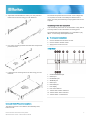
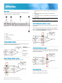
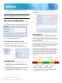
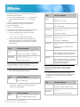
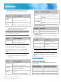
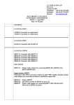
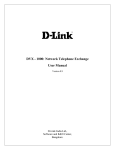
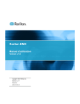
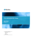
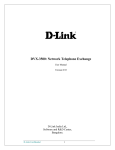
Raritan PX3TS Quick Setup Guide The PX3TS transfer switch provides AC power to rack IT equipment from one of two AC power sources, and automatically selects which source powers the load based on power availability and quality. This Quick Setup Guide is intended for experienced users. For detailed instructions, refer to the PX3TS series User Guide or online help from the Raritan website (http://www.raritan.com). Safety Precautions WARNING! Read and understand all sections in this guide before installing or operating this product. Failure to heed any of the following WARNINGS may result in electric shock, fire, personal injury and death. Prior to operating this product, the user should read the online User Guide and specifically the warnings in that Guide. WARNING! This product contains two inlet power plugs and a safety hazard may exist if one plug is disconnected and the other is connected to an energy source. Before connecting or disconnecting either inlet plug, make sure both sources of power to this product are turned off. Warranty card Two fuses (for models with fuses implemented) A null-modem cable with DB9 connectors on both ends (Raritan number: 254-01-0006-00) QS Rule Mounting the PX3TS 1. Attach mounting ears and mounting brackets to each side of the PX3TS with provided screws. WARNING! Connect this product to an AC power source whose voltage is within the range specified on the product's nameplate. WARNING! Connect this product to an AC power source that is current limited by a suitably rated fuse or circuit breaker in accordance with national and local electrical codes. WARNING! Use this product in a dry location. WARNING! Connect this product to a protective earth ground. Never use a "ground lift adaptor" between the product's plug and the wall receptacle. WARNING! If this product is a model that requires assembly of its line cord or plug, all such assembly must be performed by a licensed electrician and the line cord or plugs used must be suitably rated based on the product's nameplate ratings and national and local electrical codes. QS Rule What's Included The PX3TS device Bracket pack and screws Quick Setup Guide PX3TS Transfer Switch Quick Setup Guide QSG-PX3TS-0A-v2.6-E 255-80-0032-00 RoHS 1 2. Adjust slide-rail assemblies to match your rack posts and fasten them to the rack using your own fasteners. The PX3TS will operate when the branch circuit voltages are out of phase, but works most reliably and fastest when in phase. The front panel Phase Sync lamp lights if inlets are out of phase. Connecting Power and Equipment Your PX3TS may have fuses or circuit breakers. Verify that all are firmly seated or set to ON before connecting power. The PX3TS inlets are labeled INLET 1 (I1) and INLET 2 (I2). INLET 1 is the factory default preferred inlet. To make power connections: 3. Line up the mounting brackets with slide-rails and push this product into rails. 4. Fasten the front mounting ears to the rack using your own fasteners. 1. Connect PX3TS inlets to branch circuits. 2. Connect loads to PX3TS outlets. 3. Apply power to branch circuits. QS Rule Front View 1. CONSOLE/MODEM port 2. USB-B port 3. ETHERNET port 4. SENSOR port 5. USB-A port 6. FEATURE port 7. LCD display 8. LCD control buttons 9. Transfer switch status indicators 10. Transfer switch alarm indicators 11. Transfer switch control buttons QS Rule QS Rule Inlet and Outlet Power Connections The PX3TS connects to two different, but identically rated, branch circuits. PX3TS Transfer Switch Quick Setup Guide QSG-PX3TS-0A-v2.6-E 255-80-0032-00 RoHS 2 Rear View This is the rear view of PX3TS-1876R. Your PX3TS may look slightly different if it is a different model. Normal (green): Power quality (voltage and frequency) is good. Warning (orange): Power quality is not optimal but acceptable. Critical (red): Power is not available or power quality is not acceptable. Note: See Power Quality Setup (on page 5) for how to configure voltage and frequency settings. QS Rule Inlet Configuration Indicator Lamps The preferred inlet powers the outlets unless its power quality goes critical. A green LED indicates which inlet is preferred. The default is Inlet 1. The Manual Transfer button may change the preferred inlet. See Control Push Buttons (on page 4). 1. 2. 3. 4. 5. Inlets Fuses - one per inlet Outlets USB-A port CONSOLE port QS Rule Testing Indicator Lamps Press the Lamp Test control button and visually verify that all transfer switch indicator lamps turn on. QS Rule Active Inlet Indicator Lamps A green LED indicates which inlet is powering the outlets. Only one LED is on at a time. The Manual Transfer button transfers power to the other inlet. QS Rule Power Quality Indicator Lamps Inlet power quality is shown using a tricolor LED. QS Rule Operating Modes Normal: The preferred inlet is active. Standby: The alternate inlet is active. PX3TS Transfer Switch Quick Setup Guide QSG-PX3TS-0A-v2.6-E 255-80-0032-00 RoHS 3 Off: Neither inlet is active because of an alarm or internal failure or because both inlets go critical. See Manual Transfers (on page 4) for restoring power. Lamp Meaning Overload Power to load is turned off due to a short circuit. QS Rule Automatic Transfers An automatic transfer to the alternate inlet occurs when the preferred inlet's power quality goes critical. QS Rule Control Push Buttons An automatic retransfer back to the preferred inlet occurs when the preferred inlet's power quality returns to normal. Note: See Transfer Options Setup (on page 5) for retransfer settings. QS Rule Manual Transfers The Manual Transfer button changes the active inlet and also sets the newly-activated inlet to be the preferred inlet. The Manual Transfer button is disabled when an alarm lamp is active. Use this procedure to override the alarm and force a manual transfer. Button Action taken when pressed Alarm Override 1. Correct the problem in load that caused the alarm. 2. While holding down the Alarm Override button, press Manual Transfer. Forces a manual transfer during an alarm condition. Lamp Test Turns on all transfer switch indicator lamps. Power Quality LEDs turn orange. Note: This procedure does not apply when the Manual Disabled or Fuse alarm lamp is turned on. Manual Transfer Transfers power to the other inlet. Newly-activated inlet becomes the preferred inlet. QS Rule Alarm Indicator Lamps QS Rule PX3TS Configuration STEP 1: Connect the PX3TS to Your Network 1. Connect a standard Category 5e/6 UTP cable to the ETHERNET port on the PX3TS. 2. Connect the other end of the cable to your LAN. Note: You can also use a wireless network. See Wireless Configuration (on page 8). Lamp Meaning Step 2: Display the DHCP-Assigned IPv4 Address Manual Disabled The front panel Manual Transfer button is disabled. 1. Press the MODE button until device settings are displayed, indicated by a 'd' in at the top left of the display. Phase Sync Inlets are out of phase. Fuse Blown fuse. Replacement is Bussmann FWC-32A10F or equivalent. Internal Failure Internal hardware failure. Contact Raritan technical support. The web interface contains additional indicators for specific internal failures. PX3TS Transfer Switch Quick Setup Guide QSG-PX3TS-0A-v2.6-E 255-80-0032-00 RoHS 2. The LCD display cycles between the four octets of the IPv4 address, indicated by "i4" at the upper right corner of the display. 4 For example, 192.168.84.4 cycles in this sequence: 192, 168, 84, 4 5. (Optional) Thresholds for inlet phase angle difference reporting. Values do not affect phase sync detection or transfers. Note: If your network only supports IPv6 or static IPv4 addresses, the IP address must be configured using a serial or USB port. See Addendum (on page 6) for instructions. Step 3: Log in to the PX3TS Web Interface 1. Open a browser and type the IP address of the PX3TS device. 2. The default credentials are: user admin, password raritan. Power Quality Setup 3. Click Login. The PX3TS home page displays. 4. Change the password if prompted. Step 4: PX3TS Web Configuration Overview 1. From the Dominion PX Explorer pane, click the Transfer Switch icon. 2. Click Setup to configure the transfer options. 3. Click Power Quality Setup to configure power quality. Inlet power quality state (normal/warning/critical) is derived from the inlet's voltage and frequency quality - whichever is lower. If voltage or frequency is critical, power quality is critical. If either is warning, quality is warning. When both are normal, power quality is normal. PX3TS transfers to standby operation when preferred inlet power quality goes critical and retransfers to normal operation when power quality returns to normal. The warning state does not cause transfers and is intended as an early warning indication of a possible problem. When quality goes from better to worse, the state change is said to assert. You configure how long the quality must remain in the worse state before the state change actually occurs. When quality goes from worse to better, the state change is said to deassert. You configure the hysteresis - how much the quality must be better than the threshold - before the state change occurs. Transfer Options Setup 1. Enable/disable the front panel Manual Transfer button. 2. Enable/disable automatic retransfer. Retransfer is the transfer back to normal operation when preferred inlet power is restored. 3. Enter the time (seconds) preferred inlet power must be in the normal state before retransfer occurs. 4. Enable/disable retransfer when inlets are out of phase. PX3TS Transfer Switch Quick Setup Guide QSG-PX3TS-0A-v2.6-E 255-80-0032-00 RoHS Voltage and frequency configuration is identical. 1. Enter upper and lower thresholds for warning and critical. 2. Enter assertion times (seconds). 5 3. Enter deassertion hysteresis values. There are two ways to install this driver: automatic and manual installation. Automatic driver installation is highly recommended. Automatic driver installation in Windows®: 1. Make sure the PX3TS is NOT connected to the computer via a USB cable. 2. Run dominion-serial-setup-2.0.exe and follow online instructions to install the driver. Note: If any Windows security warning appears, accept it to continue the installation. 3. Connect the PX3TS to the computer via a USB cable. The driver is automatically installed. Note: Manually install the driver only if the automatic installation fails. See the section titled "Installing the USB-to-Serial Driver (Optional)" in the online User Guide for manual installation procedure. In Linux: QS Rule Addendum Network Configuration via an RS-232 or USB Port Step 1: Connect the PX3TS to a Computer Connect the PX3TS to a computer via an RS-232 or USB cable. RS-232 connection: 1. Connect one end of the null-modem cable to the RS-232 port labeled CONSOLE/MODEM on the PX3TS. 2. Connect the other end to your computer's RS-232 port (COM). USB connection: 1. A USB-to-serial driver is required in Windows®. Install this driver before connecting the USB cable. See Installing the USB-to-Serial Driver (Optional) (on page 6). 2. Connect one end of a USB cable to the USB-B port on the PX3TS. 3. Connect the other end to your computer's USB-A port. Installing the USB-to-Serial Driver (Optional) The PX3TS can emulate a USB-to-serial converter over a USB connection. A USB-to-serial driver named "Dominion PX2 Serial Console" is required for Microsoft® Windows® operating systems. Download the USB Serial Setup 2.0 driver file, which contains dominion-serial.inf, dominion-serial.cat and dominion-serial-setup.exe files, from the PX2 section on the Raritan website (http://www.raritan.com). PX3TS Transfer Switch Quick Setup Guide QSG-PX3TS-0A-v2.6-E 255-80-0032-00 RoHS No additional drivers are required, but you must provide the name of the tty device, which can be found in the output of the "dmesg" after connecting the PX3TS to the computer. Usually the tty device is "/dev/ttyACM#" or "/dev/ttyUSB#," where # is an integer number. For example, if you are using the kermit terminal program, and the tty device is "/dev/ttyACM0," perform the following commands: > set line /dev/ttyACM0 > connect STEP 2: Configure the PX3TS 1. On the computer connected to the PX3TS, open a communications program such as HyperTerminal or PuTTY. 2. Select the appropriate COM port, and set the following port settings: Bits per second = 115200 (115.2Kbps) Data bits = 8 Stop bits = 1 Parity = None Flow control = None Tip: For a USB connection, you can determine the COM port by choosing Control Panel > System > Hardware > Device Manager, and locating the "XXX Serial Console" under the Ports group, where XXX represents this product's name. 3. In the communications program, press Enter to send a carriage return to the PX3TS. 6 4. The PX3TS prompts you to log in. Both user name and password are case sensitive. a. At the Username prompt, type admin and press Enter. b. At the Password prompt, type raritan and press Enter. 5. If you are prompted to change the password, follow onscreen instructions to type your new password. 6. The # prompt appears. 7. Type config and press Enter. 8. To configure network settings, type appropriate commands, and press Enter. All commands are case sensitive. a. To set the networking mode, type this command: network mode <mode> where <mode> is wired (default) or wireless. b. For the wired network mode, you may configure the LAN interface settings. In most scenarios, the default setting (auto) works well and should not be changed unless required. To set Use this command LAN interface speed network interface LANInterfaceSpeed <option> To set Use this command Authentication method network wireless authMethod <method> <method> = psk or eap PSK <psk> = PSK string EAP outer authentication network interface LANInterfaceDuplexMode <mode> EAP inner authentication c. For the wireless network mode, you must configure the Service Set Identifier (SSID) parameter. To set Use this command SSID network wireless SSID <ssid> <ssid> = SSID string If necessary, configure more wireless parameters shown in the following table. To set Use this command BSSID network wireless BSSID <bssid> network wireless eapInnerAuthentication <inner_auth> <inner_auth> = MSCHAPv2 EAP identity network wireless eapIdentity <identity> <identity> = your user name for EAP authentication EAP passord network wireless eapPassword When prompted to enter the password for EAP authentication, type the password. EAP CA certificate <mode> = half, full or auto. Tip: You can combine multiple commands to configure multiple parameters at a time. For example, network interface LANInterfaceSpeed <option> LANInterfaceDuplexMode <mode> network wireless eapOuterAuthentication <outer_auth> <outer_auth> = PEAP <option> = auto, 10Mbps, or 100Mbps. LAN interface duplex mode network wireless PSK <psk> network wireless eapCACertificate When prompted to enter the CA certificate, open the certificate with a text editor, copy and paste the content into the communications program. Note: The content to be copied from the CA certificate does NOT include the first line containing "BEGIN CERTIFICATE" and the final line containing "END CERTIFICATE." d. To determine which IP protocol (IPv4 or IPv6) is enabled and which IP address (IPv4 or IPv6) returned by the DNS server is used, configure the following parameters. To set Use this command IP protocol network ip proto <protocol> <protocol> = v4Only, v6Only or both IP address returned by the DNS server network ip dnsResolverPreference <resolver> <resolver> = preferV4 or preferV6 <bssid> = AP MAC address or none PX3TS Transfer Switch Quick Setup Guide QSG-PX3TS-0A-v2.6-E 255-80-0032-00 RoHS 7 e. After enabling the IPv4 or IPv6 protocol in the earlier step, configure the IPv4 or IPv6 network parameters. To set Use this command IPv4 configuration method network ipv4 ipConfigurationMode <mode> IPv6 configuration method network ipv6 ipConfigurationMode <mode> Use this command IPv4 or IPv6 primary DNS server network <version> primaryDNSServer <ip address> <ip address> = IP address of the primary DNS server network <version> IPv4 or IPv6 secondary DNS secondaryDNSServer <ip address> server (optional) <ip address> = IP address of the secondary DNS server <mode> = dhcp (default) or static <mode> = automatic (default) or static To set 9. To quit the configuration mode, type either of the following commands, and press Enter. Configure the preferred host name for the IPv4 DHCP or IPv6 automatic configuration. Note: The <version> variable in all of the following commands is either ipv4 or ipv6, depending on the type of the IP protocol you have enabled. Command Description apply Save all configuration changes and exit. cancel Abort all configuration changes and exit. The # prompt appears, indicating that you have quit the configuration mode. 10. To verify whether all settings are correct, type the following commands one by one. To set Use this command Preferred host name (optional) network <version> preferredHostName <name> <name> = preferred host name Tip: To override the DHCP-assigned DNS servers with those you specify manually, type this command: network <version> overrideDNS <option> where <option> is enable or disable. See the table below for the commands for manually specifying DNS servers. For the static IP configuration, configure these parameters. Command Description show network Show network parameters. show network ip all Show all IP configuration parameters. show network wireless details Show all wireless parameters. Tip: You can type "show network wireless" to display a shortened version of wireless settings. 11. If all are correct, type exit to log out of the PX3TS. If any are incorrect, repeat Steps 7 to 10 to change network settings. QS Rule Wireless Configuration To set Use this command USB Wireless LAN Adapters Static IPv4 or IPv6 address network <version> ipAddress <ip address> The following table lists USB wireless LAN adapters that the PX3TS supports. <ip address> = static IP address IPv4 subnet mask network ipv4 subnetMask <netmask> IPv4 or IPv6 gateway network <version> gateway <ip address> <netmask> = subnet mask <ip address> = gateway's IP address PX3TS Transfer Switch Quick Setup Guide QSG-PX3TS-0A-v2.6-E 255-80-0032-00 RoHS Wi-Fi LAN adapter Supported 802.11 protocols Proxim Orinoco 8494 A/B/G Zyxel NWD271N B/G Edimax EW-7722UnD A/B/G/N Raritan USB WIFI A/B/G/N 8 Note: To use the Edimax EW-7722UnD or Raritan USB WIFI wireless LAN adapter to connect to an 802.11n wireless network, the handshake timeout setting must be changed to 500 or greater, or the wireless connection will fail. Contact Support page in the Support section on Raritan's website for technical support contact information worldwide. Raritan's products use code licensed under the GPL and LGPL. You can request a copy of the open source code. For details, see the Open Source Software Statement at (http://www.raritan.com/about/legal-statements/open-source-software-statement /) on Raritan's website. Built-in Wireless LAN Adapters If the Raritan product you purchased has been implemented with the following 802.11 wireless LAN adapter when shipping out of the factory, no USB wireless LAN adapters are required to make a wireless connection. Wi-Fi LAN adapter Supported 802.11 protocols HD-Wireless B/G Supported Wireless LAN Configuration If a wireless connection is preferred, ensure that the wireless LAN configuration of your PX3TS matches the access point. The following is the wireless LAN configuration that the PX3TS supports. Network type: 802.11 A/B/G/N Protocol: WPA2 (RSN) Key management: WPA-PSK, or WPA-EAP with PEAP and MSCHAPv2 authentication Encryption: CCMP (AES) Important: Raritan only supports specific wireless LAN adapters. Supported 802.11 network protocols vary according to the wireless LAN adapter being used with the PX3TS. See USB Wireless LAN Adapters (on page 8). Making a Wireless Connection The PX3TS can be connected to a wireless network. To make a wireless connection: Do one of the following: Plug a supported USB wireless LAN adapter into the USB-A port on your PX3TS. Connect a USB docking station to the USB-A port on the PX3TS and plug the supported USB wireless LAN adapter into the appropriate USB port on the docking station. See USB Wireless LAN Adapters (on page 8) for a list of supported wireless LAN adapters. QS Rule Additional Information For more information about the PX3TS® and the entire Raritan product line, see Raritan's website (www.raritan.com). For technical issues, contact Raritan Technical Support. See the PX3TS Transfer Switch Quick Setup Guide QSG-PX3TS-0A-v2.6-E 255-80-0032-00 RoHS 9