1
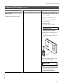
Please file in Service Binder Operating Instructions & User’s Information Manual Vitodens 200 WB2 Series Wall-mounted, gas-fired condensing boiler For natural gas and liquid propane Heating input NG 25 to 230 MBH 7 to 67 kW Heating input LP 25 to 214 MBH 7 to 63 kW VITODENS 200 WARNING If the information in this manual is not followed exactly, a fire or explosion may result causing property damage, personal injury or loss of life. Do not store or use gasoline or other flammable liquids in the vicinity of this or any other appliance. IMPORTANT Read and save these instructions for future reference. WHAT TO DO IF YOU SMELL GAS Do not try to light any appliances. Do not touch any electrical switches, do not use any phone in your building. Immediately call your gas supplier from a neighbor’s phone. Follow the gas supplier’s instructions. If you cannot reach your gas supplier, call the fire department. Installation and service must be performed by a qualified installer, service agency or the gas supplier. WARNING Improper installation, adjustment, and/or operation could cause carbon monoxide poisoning resulting in injury or loss of life. This product must be installed and serviced by a professional service technician who is experienced and qualified in hot water boiler installation and gas combustion. 5167 475 v1.2 07/2007 Safety, Installation and Warranty Requirements Safety, Installation and Warranty Requirements Please ensure that these instructions are read and understood before commencing installation. Failure to comply with the instructions listed below and details printed in this manual can cause product/property damage, severe personal injury, and/or loss of life. Ensure all requirements below are understood and fulfilled (including detailed information found in manual subsections). H Licensed professional heating contractor The installation, service, and maintenance of this equipment must be performed by a licensed professional heating contractor. Please see section entitled “Important Regulatory and Installation Requirements” in the Installation Instructions. " H Product documentation Read all applicable documentation before commencing installation. Store documentation near boiler in a readily accessible location for reference in the future by service personnel. For a listing of applicable literature, please see section entitled “Important Regulatory and Installation Requirements” in the Installation Instructions. H Carbon monoxide Improper installation, service and/or maintenance can cause flue products to flow into living space. Flue products contain poisonous carbon monoxide gas. For information pertaining to the proper installation, service and maintenance of this equipment to avoid formation of carbon monoxide, please see the Installation Instructions of the Vitodens 200 Direct Vent System. H Equipment venting Never operate boiler without an installed venting system. An improper venting system can cause carbon monoxide poisoning. " H Warranty Information contained in this and related product documentation must be read and followed. Failure to do so renders warranty null and void. WARNING Installers must follow local regulations with respect to installation of carbon monoxide detectors. Follow manufacturer’s maintenance schedule of boiler. " 5167 475 v1.2 H Advice to owner Once the installation work is complete, the heating contractor must familiarize the system operator/ultimate owner with all equipment, as well as safety precautions/requirements, shut-down procedure, and the need for professional service annually before the heating season begins. 2 Index Page General Information About these Instructions. . . . . . . . . . . . . . . . . . . . . . . . . . . . . . . . . . . . . . . . . . . . . . . . . . . . . . . . 5 Safety For your Safety 5 Useful Tips Quick Reference Reference Guide ........................................................................ Inform Yourself. . . . . . . . . . . . . . . . . . . . . . . . . . . . . . . . . . . . . . . . . . . . . . . . . . . . . . . . . . . . . . . . . . . . . . . . . . 9 Getting started... . . . . . . . . . . . . . . . . . . . . . . . . . . . . . . . . . . . . . . . . . . . . . . . . . . . . . . . . . . . . . . . . . . . . . 9 Your Vitodens 200 boiler. . . . . . . . . . . . . . . . . . . . . . . . . . . . . . . . . . . . . . . . . . . . . . . . . . . . . . . . 10 Overview of controls and indicators . . . . . . . . . . . . . . . . . . . . . . . . . . . . . . . . . . 10 Ready for Operation . . . . . . . . . . . . . . . . . . . . . . . . . . . . . . . . . . . . . . . . . . . . . . . . . . . . . . . . . . . . . . . . . The main control options . . . . . . . . . . . . . . . . . . . . . . . . . . . . . . . . . . . . . . . . . . . . . . . . . . . . . . . Your heating system comes factory preset... . . . . . . . . . . . . . . . . . Selecting a heating program (winter, summer). . . . . . . . . . . . . . . Changing room temperature . . . . . . . . . . . . . . . . . . . . . . . . . . . . . . . . . . . . . . . . . . . . . . . . . 12 12 12 13 14 Using Comfort Functions . . . . . . . . . . . . . . . . . . . . . . . . . . . . . . . . . . . . . . . . . . . . . . . . . . . . . . Switching DHW comfort function on/off. . . . . . . . . . . . . . . . . . . . . . . . . . Setting the party mode . . . . . . . . . . . . . . . . . . . . . . . . . . . . . . . . . . . . . . . . . . . . . . . . . . . . . . . . . . Activating the energy saving mode . . . . . . . . . . . . . . . . . . . . . . . . . . . . . . . . . . . Using the remote programming option. . . . . . . . . . . . . . . . . . . . . . . . . . . . . . 14 14 15 15 16 Switching On and Off . . . . . . . . . . . . . . . . . . . . . . . . . . . . . . . . . . . . . . . . . . . . . . . . . . . . . . . . . . . . . 16 Initial start-up and re-starting the heating system. . . . . . . . . 16 Shutting down the heating system . . . . . . . . . . . . . . . . . . . . . . . . . . . . . . . . . . . . 17 Menu-driven Operation . . . . . . . . . . . . . . . . . . . . . . . . . . . . . . . . . . . . . . . . . . . . . . . . . . . . . . . . . . . 18 The programming unit is your assistant . . . . . . . . . . . . . . . . . . . . . . . . . . . 18 Space Heating Settings (Switching Times) . . . . . . . . . . . . . . . . . . . . . . 19 How switching times work... . . . . . . . . . . . . . . . . . . . . . . . . . . . . . . . . . . . . . . . . . . . . . . . 19 Scanning and changing switching times . . . . . . . . . . . . . . . . . . . . . . . . . . 19 Domestic Hot Water Supply Settings (Switching Times). . . . . . . . . . . . . . . . . . . . . . . . . . . . . . . . . . . . . . . . . . . . . . . . . . . . . . . . . . . . . . . . . . . . . How switching times work... . . . . . . . . . . . . . . . . . . . . . . . . . . . . . . . . . . . . . . . . . . . . . . . Scanning and changing switching times . . . . . . . . . . . . . . . . . . . . . . . . . . Changing the domestic hot water temperature. . . . . . . . . . . . . . 21 21 21 23 When you go on holidays... . . . . . . . . . . . . . . . . . . . . . . . . . . . . . . . . . . . . . . . . . . . . . . . . . . 24 Setting the energy saving mode for the holiday period 24 25 25 25 25 26 5167 475 v1.2 Other Settings . . . . . . . . . . . . . . . . . . . . . . . . . . . . . . . . . . . . . . . . . . . . . . . . . . . . . . . . . . . . . . . . . . . . . . . . . . Changing time and date . . . . . . . . . . . . . . . . . . . . . . . . . . . . . . . . . . . . . . . . . . . . . . . . . . . . . . . . . Scanning temperatures and operating status. . . . . . . . . . . . . . . . . . Selecting the language . . . . . . . . . . . . . . . . . . . . . . . . . . . . . . . . . . . . . . . . . . . . . . . . . . . . . . . . . . . Changing the heating pattern of the boiler . . . . . . . . . . . . . . . . . . . . . . 3 Emission Inspection Information Override Switch/Emission Test Switch . . . . . . . . . . . . . . . . . . . . . . . . . . . . . 28 Troubleshooting Guide. . . . . . . . . . . . . . . . . . . . . . . . . . . . . . . . . . . . . . . . . . . . . . . . . . . . . . . . . . . . 29 Diagnosis and correction . . . . . . . . . . . . . . . . . . . . . . . . . . . . . . . . . . . . . . . . . . . . . . . . . . . . . . . 29 Service Instructions . . . . . . . . . . . . . . . . . . . . . . . . . . . . . . . . . . . . . . . . . . . . . . . . . . . . . . . . . . . . . . . . 32 Service instructions for your heating system . . . . . . . . . . . . . . . . . 32 How to Save Energy . . . . . . . . . . . . . . . . . . . . . . . . . . . . . . . . . . . . . . . . . . . . . . . . . . . . . . . . . . . . . . . 33 Directories . . . . . . . . . . . . . . . . . . . . . . . . . . . . . . . . . . . . . . . . . . . . . . . . . . . . . . . . . . . . . . . . . . . . . . . . . . . . . . . . . . Overview of menu structures . . . . . . . . . . . . . . . . . . . . . . . . . . . . . . . . . . . . . . . . . . . . . . Lighting and operating instructions. . . . . . . . . . . . . . . . . . . . . . . . . . . . . . . . . . . . . Alphabetical index . . . . . . . . . . . . . . . . . . . . . . . . . . . . . . . . . . . . . . . . . . . . . . . . . . . . . . . . . . . . . . . . . . . 4 34 34 36 39 General Information/Safety About these Instructions Take note of all symbols and notations intended to draw attention to potential hazards or important product information. These include ”WARNING”, ”CAUTION”, and ”IMPORTANT”. See below. WARNING Indicates an imminently hazardous situation which, if not avoided, could result in death, serious injury or substantial product/property damage. CAUTION Indicates an imminently hazardous situation which, if not avoided, may result in minor injury or product/property damage. IMPORTANT Warnings draw your attention to the presence of potential hazards or important product information. Cautions draw your attention to the presence of potential hazards or important product information. Helpful hints for installation, operation or maintenance which pertain to the product. This symbol indicates that additional, pertinent information is to be found in column three. This symbol indicates that other instructions must be referenced. For your Safety H Operation Before operating the boiler, make sure you fully understand its method of operation. Your heating contractor should always perform the initial start-up and explain the system. Any warranty is null and void if these instructions are not followed. H Flue gas smell 5167 475 v1.2 - Deactivate heating equipment. - Open windows and doors. - Inform your heating contractor. H Working on the equipment All personnel working on the equipment or the heating system must have the proper qualifications and hold all necessary licenses. Ensure main power to equipment, heating system, and all external controls has been deactivated. Close main gas supply valve. Take precautions in all instances to avoid accidental activation of power during service work. H Dangerous conditions - Deactivate main power immediately. - Close gas supply valve. H Maintenance and cleaning Regular inspection and service by a qualified heating contractor is important to the performance of the Viessmann Vitodens 200. Neglected maintenance impacts on warranty; regular inspection ensures clean, environmentally friendly and efficient operation. We recommend a maintenance contract with a qualified heating contractor. H Technical information Literature applicable to all aspects of the Vitodens 200: - Technical Data Manual - Installation Instructions - Start-up/Service Instructions - Operating Instructions and User’s Information Manual - System Design Guidelines Additional applicable literature: - Accessory manuals 5 Safety For your Safety (continued) H Carbon monoxide The U.S. Consumer Product Safety Commission strongly recommends the installation of carbon monoxide detectors in buildings in which gas-burning equipment is installed. Carbon monoxide (CO) is a colorless, odorless gas, which may be produced during incomplete combustion of fuel and/or when the flame does not receive an adequate supply of combustion air. Carbon monoxide can cause severe personal injury or loss of life. Therefore, carbon monoxide detectors that are in compliance with a nationally recognized standard (e.g. ANSI/UL 2034-2002, CSA 6.19-01) should be installed and maintained in buildings that contain gas-burning equipment. Note: Viessmann does not test any detectors and makes no representation regarding any brand or type of detector. H For safe operation We recommend that you frequently: - Check for debris which could obstruct the flow of flue gases. The vent or chimney must not be blocked. A blocked or partially blocked vent or chimney can cause flue gases to leak into the structure. Flue gases leaking into the house can cause injury or death. Blocked or partially blocked chimneys must have the blockage removed by a qualified heating contractor. - Check pressure gage for correct system (water) pressure. Check for water on the floor from the discharge pipe of the pressure relief valve or any other pipe, pipe joint, valve or air vent. - Check for moisture, water, or appearance of rust on the flue gas pipes, their joints as well as vent dampers, or side wall vent terminals (if so equipped). - Ensure that nothing is obstructing the flow of combustion and ventilation air and no chemicals, garbage, gasoline, combustible materials, flammable vapors and liquids are stored (not even temporarily) in the vicinity of the boiler. - Do not allow unsupervised children near the boiler. Service/inspection of the boiler and the system is recommended once a year. Maintenance, service and cleaning are specified in the Installation Instructions. Before the heating season begins, it is recommended that the boiler and burner be serviced by a qualified heating contractor. Service contracts may be established through gas suppliers or other licensed contractors in your area. WARNING As there are no user-serviceable parts on the boiler, burner or control, the end-user must not perform service activities or adjustments of any kind on system components. Failure to heed this warning can cause property damage, severe personal injury, or loss of life. WARNING Improper installation, adjustment, service, or maintenance can cause flue products to flow into living space. Flue products contain poisonous carbon monoxide gas which can cause nausea or asphyxiation resulting in severe personal injury or loss of life. CAUTION Should overheating occur or the gas supply fail to shut off, do not disconnect the electrical supply to the pump. Instead, shut off the gas supply at a location external to the appliance. WARNING The operator/ultimate owner is required to have the heating boiler, burners, and controls checked, as a minimum once per year, by the original installer or by a competent heating contractor familiar with the equipment. Defects must be corrected immediately. CAUTION 5167 475 v1.2 Do not use this boiler if any part has been under water. Immediately call a qualified heating contractor to inspect the boiler and to replace any part of the control system and any gas control which has been under water. 6 Safety For your Safety (continued) Frozen water pipe hazard WARNING Failure to protect against frozen pipes could result in burst water pipes, serious property damage and/or personal injury. Boiler may shut down. Do not leave your home unattended for long periods of time during freezing weather conditions without turning off the water supply and draining water pipes or otherwise protecting against the risk of frozen pipes. Your heating boiler is designed to provide a warm and comfortable living environment. It is NOT designed to ensure against freezing of water pipes. The boiler is equipped with several safety devices that are designed to shut down the boiler and to prevent it from restarting in the event of various unsafe conditions. If your home will be unattended for an extended period of time during cold weather, you should... H Shut off the water supply to the building, drain the water pipes and add an antifreeze for potable water to drain traps and toilet tanks. Open faucets where appropriate. Or.. H Have someone check the building frequently during cold weather and call a qualified service agency if required. Or... H Install a reliable remote temperature sensor that will notify somebody of freezing conditions within the home. 5167 475 v1.2 If your boiler remains off for an extended period of time during cold weather, water pipes may freeze and burst, resulting in extensive water damage and conditions in which mold could grow. Certain molds are known to cause respiratory problems, as well as to pose other serious health risks. In case of water damage, immediate measures should be taken to dry out affected areas as quickly as possible to prevent mold from developing. 7 Safety For your Safety (continued) If you notice fire coming from the appliance, call the fire department immediately! Do not attempt to extinguish the fire unless qualified to do so. WARNING Fire causes a risk of burns and explosion! H Shut down the boiler H Close fuel shut-off valves H Use a tested fire extinguisher, class ABC. Installation area conditions WARNING Incorrect ambient conditions can lead to damage to the heating system and put safe operation at risk. H Ensure ambient temperatures are higher than 32°F / 0°C and lower than 104°F / 40°C. H Prevent the air from becoming contaminated by halogenated hydrocarbons (e.g. as contained in paints solvents or cleaning fluids) and excessive dust (e.g. through grinding or polishing work). Combustion air for the heating process, and ventilation of the boiler room must be free of corrosive contaminants. To that end, any boiler must be installed in an area that has no chemical exposure. The list to the right indicates the main, currently known sources. H Avoid continuously high levels of humidity (e.g. through frequent drying of laundry). H Never close existing ventilation openings. Sources of combustion and ventilation air contaminants Areas likely to contain contaminants: H New building construction H Swimming pools H Remodelling areas, hobby rooms H Garages with workshops H Furniture refinishing areas H Dry cleaning/laundry areas and establishments H Auto body shops H Refrigeration repair shops H Metal fabrication plants H Plastic manufacturing plants H Photo processing plants H Beauty salons Products containing contaminants: H Chlorine-type bleaches, detergents and 5167 475 v1.2 cleaning solvents found in household laundry rooms H Paint and varnish removers H Hydrochloric acid, muriatic acid H Chlorine-based swimming pool chemicals H Spray cans containing chlorofluorocarbons H Chlorinated waxes and cleaners H Cements and glues H Refrigerant leaks Replacement components, spare and wear H Calcium chloride used for thawing H Sodium chloride used for water parts softening salt H Permanent wave solutions IMPORTANT H Adhesives used to fasten building products and other similar items H Antistatic fabric softeners used in Components which are not tested with clothes dryers the heating system may damage the heating system, or affect its functions. Installation or replacement may only be carried out by a qualified heating contractor. 8 Inform Yourself Getting Started... The timer of the control unit switches between ”normal room temperature” and ”reduced room temperature” at the required times. 1. Normal room temperature for the times you spend at home and require a comfortably warm room temperature (e.g. 68 ºF/20 ºC). 2. Reduced room temperature for the times you are away from home. To save energy, a lower temperature is typically selected (e.g. 57 ºF/14 ºC). Times and duration of the two room temperatures can be set on the programming unit of your control. The temperature settings for both the ”normal room temperature” and ”reduced room temperature” can be set according to your personal preference. The timer of the control unit switches domestic hot water production on and off at the required times. 1. Domestic hot water heating can be set to take place during the times you spend at home and require hot water for your daily DHW requirements (e.g. for showering). Times and duration of the domestic hot water production period can be set on the programming unit of your control. 2. Domestic hot water heating can be set not to take place for the times you spend sleeping, for example. The domestic hot water recirculation pump (if installed) ensures that domestic hot water is readily available when domestic hot water is drawn. 5167 475 v1.2 You may select a DHW temperature setting based on your personal preference of up to 140 ºF/60 ºC. 9 Inform Yourself Your Vitodens 200 Boiler Please ask your heating contractor to check off the appropriate box ( ). j Vitodens 200 without domestic hot water tank j Vitodens 200 with separate domestic hot water tank The control unit activates and deactivates space heating and supplies rooms with heat. j Vitodens 200 with integrated DHW plate heat exchanger for instantaneous DHW heating Domestic hot water heating has priority over space heating. The control unit switches automatically to space heating when the preset domestic hot water temperature is reached. Domestic hot water heating has priority over space heating. The control unit switches automatically to space heating when the heat exchanger temperature is satisfied (with comfort switch on) or when the preset domestic hot water temperature is reached (with comfort switch off). Overview of Controls and Indicators Programming Unit (removable) Pressure gage Display window Heating program selector switch Burner fault reset button 15 1 0 0 30 2 Emission test switch (override switch) 45 3 60 3 2 1 4 5 6 0 A B C D - + i 3 2 1 7 8 9 10 4 5 6 7 8 9 10 Selector knob for ”normal room temperature” Burner operating status indicator Burner fault indicator Boiler on/off switch Party button Energy savings button Selector knob for ”reduced room temperature” Information button ”Factory default settings” button Selector knob Flip-down cover Selector buttons 5167 475 v1.2 DHW comfort function switch (only operational on Combi heating boiler with integrated instantaneous hot water heating) 10 Inform Yourself Overview of Controls and Indicators MAIN MENU Operation The is a menu-driven programming unit. Upon opening the flip-down cover of the programming unit, the start menu showing all available adjustment options will appear in the display window. Select your adjustment option by pressing buttons “A”, “B”, “C” or “D”. An overview of the menu structures available can be found in section entitled “Overview of menu structures” on page 34 of this manual. 5167 475 v1.2 Please select >HTG. CIRCUIT A: . . . . . . . . . . . . . . A >HTG. CIRCUIT B: . . . . . . . . . . . . . . B >DHW: . . . . . . . . . . . . . . . . . . . . . . . . C >SYSTEM: . . . . . . . . . . . . . . . . . . . . . D >EXIT: . . . . . . . . . . . . . . CLOSE COVER (continued) 11 Ready for Operation The Main Control Options All settings can be adjusted directly on the boiler control or on the remote control (when the programming unit is used as remote control). The programming unit can be removed from the control unit and mounted on a wall-mount base (available as accessory) anywhere in your main living area and used as a remote control. In instances where the programming unit is used as remote control, a temperature indicator (available as accessory) must be installed in place of the programming unit in the control base on the boiler. The control unit is located behind the hinged cover in the front of the boiler. Open hinged cover of the control by exerting slight pressure with your fingertip on top of the cover. Ensure hinged cover is closed after every use to guarantee splash protection. Your heating system comes factory preset ... The control unit comes factory preset to a standard operating mode. This means your heating system is ready for operation. All factory default settings can be changed to reflect your personal preferences. Date and time The date and time are factory preset and are updated through the built-in long-life battery. Should time and/or date be incorrect please see section entitled “Changing Time and Date” on page 25 in this manual. Heating program The heating program is set to ”Space heating and domestic hot water”, i.e. space heating and domestic hot water production take place in accordance with preset switching times. 5167 475 v1.2 Switching times The switch-on time is set to 6:00 hrs, the switch-off time to 22:00 hrs. Between 6:00 hrs and 22:00 hrs, space heating takes place at normal room temperature with domestic hot water production (if installed) when required. Between 22:00 hrs and 6:00 hrs, space heating takes place at reduced room temperature. Press button ”D” to reset the switching times to their factory default settings. Please note that this will reset all altered values to their original factory default setting. 12 Ready for Operation Selecting a Heating Program (winter, summer) Select one of the following heating programs according to your personal requirements. Space heating and domestic hot water H Space heating at normal or reduced room temperature according to preset switching times H Domestic hot water production (with DHW tank installed or with Combi heating boiler) H Freeze-up protection of boiler and the DHW storage tank. e.g. for winter months and transitional periods. Domestic hot water only H No space heating H Domestic hot water production (with DHW tank installed or with Combi heating boiler) H Freeze-up protection of boiler and DHW storage tank. e.g. for summer months. Standby operation H No space heating H No domestic hot water production H Freeze-up protection of boiler and DHW storage tank. e.g. for summer holiday period. IMPORTANT 5167 475 v1.2 The circulation pumps are switched on for a short time every 24 hours to prevent them from seizing up. 13 Ready for Operation/Using Comfort Functions Changing Room Temperature In the ”Space heating and domestic hot water” heating program, space heating takes place at ”normal room temperature” and ”reduced room temperature” depending on preset switching times. You can set the required room temperature as follows. Colder Warmer ”Normal room temperature” (factory default setting: 6:00 hrs to 22:00 hrs) Setting ”5” corresponds to a room temperature of approx. 68 ºF/20 ºC with a correctly adjusted heating curve. “Normal room temperature” can be set between 41 and 95 ºF/ 5 and 35 ºC. Example For the times you spend at home and require a comfortably warm room temperature. Colder Warmer ”Reduced room temperature” (factory setting: 22:00 hrs to 6:00 hrs) Setting ”e” corresponds to a room temperature of approx. 41 ºF/5 ºC with a correctly adjusted heating curve. ”Reduced room temperature” can be set between 41 and 95 ºF/ 5 and 35 ºC. Example At nighttime or when you are away from home. Changing the room temperature 1. Turn selector knob ”s” or ”m”. The (previous and current) temperature values appear in the display window. Please reference section ”Changing the heating pattern of the boiler” on page 26 in this manual. SELECTED ROOM TEMP. PREVIOUS: 20ºC CURRENT: 22ºC INFO: OPEN COVER 2. Set the (current) temperature required using the selector knob. 3. The display automatically disappears after approx. 5 seconds. The selected temperature is stored. Switching DHW Comfort Function On/Off (for Combi Series with integrated instantaneous DHW heat exchanger) With button ”/“ the comfort function can be switched on and off. 14 The DHW comfort function can be deactivated in order to avoid frequent activation of the boiler, i.e. to reduce the energy consumption used for maintaining a certain DHW temperature if no domestic hot water is drawn (e.g. at nighttime). 5167 475 v1.2 When the comfort function is activated, the integrated instantaneous hot water heating function maintains a certain domestic hot water temperature level (standby). Domestic hot water is thus readily available when required. Using Comfort Functions Setting the Party Mode Activate the party mode when you require space heating for a short period of time, independent of the preset heating program and outside the preset switching times. You can adjust the room temperature (party temperature) to suit your personal preference. MONDAY, 20.05.97 10:30 pm PARTY MODE SELECTED: 20ºC CHANGE PARTY TEMP.: OPEN COVER BOILER TEMP.: 53ºC To activate the party mode Press the party button ”g”. The party mode is now displayed together with the preset party temperature. Example Use the party mode option when you wish to stay up longer than usual (e.g. when you have guests) and require space heating without having to change the switching times. To change the room temperature (party temperature) Open the flip-down cover of the programming unit and follow the instructions in the display window. Ensure cover is closed when change is made. To cancel the party mode The party mode is cancelled automatically the next time the preset heating program switches to ”normal room temperature”. If you want to cancel the party mode immediately, press the party button ”g” again. Activating the Energy Saving Mode Activate the energy saving mode when you require particularly economical space heating for a short period of time. In the energy saving mode, the preset room temperature is automatically lowered by approx. 3.6 ºF/2 ºC. TUESDAY, 21.05.97 10:35 HRS ENERGY SAVING MODE S BOILER TEMP.: OPEN COVER To cancel the energy saving mode The energy saving mode is cancelled automatically the next time the preset heating program switches to ”reduced room temperature”. If you want to cancel the energy saving mode immediately, press the energy saving button ”S” again. Example Use the energy saving mode option when you are not at home for a period of time (e.g. to go shopping) and wish to lower the temperature without having to adjust the temperature selector switch and the switching times. 5167 475 v1.2 INFO: 53ºC To activate the energy saving mode Press the energy saving button ”S”. The energy saving mode is now displayed. 15 Using Comfort Functions/Switching On and Off Using the Remote Programming Option The programming unit provides you with the option of programming your right from your armchair. Simply remove the programming unit from the control base in the front of the boiler or, if used as remote control, from the wall-mount base, and perform your programming from wherever convenient. Be sure to insert the programming unit in the control unit or wall-mount base upon completion of your programming. 5 34 67 2 8 9 1 0 10 5 34 67 2 8 1 9 10 2 1 3 0 4 The following options can be programmed: H Time programs H Room temperature values H Heating curves H Time and date Before using the ”remote programming option” for the first time, insert the programming unit in the control unit or in the wall-mount base for approx. 2 minutes. Switch off the heating system switch on the control unit before removing and inserting the programming unit. Initial Start-up and Re-starting the Heating System Initial start-up and adjustment of the control unit to local conditions and the structural characteristics of your building must be performed by your heating contractor. We recommend that you contact your heating contractor before re-starting the heating system if it has been shut down for a long period of time. To start up the system 1. Check heating system pressure on the pressure gage 1. Minimum system pressure 12 psig. If the needle of the pressure gage is below 12 psig, the system pressure is too low, in which case you must contact your heating contractor. 2. Open the gas shutoff valve 2 (field supplied). 3. Switch on line voltage (e.g. at separate fuse/circuit breaker). 123 0 4 456 213 7 98 0 10 4567 213 9 8 10 5167 475 v1.2 4. Switch on the heating system on/off switch 3. Your heating system is now ready for operation. 16 Switching On and Off Shutting Down the Heating System In case you are not intending to use your heating system for a period of time, e.g. during your summer holidays, switch your heating system to standby operation (see section entitled ”Selecting a heating program”, page 13). If you do not want to use your heating system for a longer period of time (several months), you should shut it down. We advise you to contact your heating contractor before shutting down the heating system for longer periods of time. Your heating contractor will then take any required action/precautions, e.g. providing freeze-up protection of the system or safeguarding the heat exchanger surfaces. To shut down the heating system 1. Switch off the heating system on/off switch. 2. Close gas shutoff valve and secure against unintentional opening. All settings of the control unit still remain intact. 5167 475 v1.2 3. Switch off line voltage (e.g. at separate fuse/circuit breaker). The power supply to the system is now switched off. There is no freeze-up protection. 17 Menu-driven Operation The Programming Unit Is Your Assistant With the programming unit you can set the heating system settings according to your personal preferences and requirements by using the various functions and adjustment options offered through the programming unit. Most of the functions offered are easily accessible through the main menu. Thus switching times, temperatures and heating curves can be navigated and adjusted in a straight-forward fashion. MAIN MENU MENU MAIN PLEASEselect SELECT! Please >HTG. CIRCUIT .A >HTG. CIRCUIT A: A: . .. .. .. .. .. .. .. .. .. .. .. . A >HTG. CIRCUIT . B >HTG. CIRCUIT B: B: .. .. .. .. .. .. .. .. .. .. .. .. . B >DHW: .. .. .. .. .. .. .. .. .. .. .. .. .. .. .. .. .. .. .. .. .. .. . C . C >DHW: >SYSTEM: >SYSTEM: .. .. .. .. .. .. .. .. .. .. .. .. .. .. .. .. .. .. .. . D .D >EXIT: CLOSE COVER >EXIT: . . . . . . . CLOSE COVER Information button D Factory default setting Display window (with cover open) Overview of possible settings G Selector knob Flip-down cover A, B, C, D Selector buttons 18 The steps required to make individual settings are explained in detail on the following pages. You will find an overview of the menu structures (in section entitled ”Overview of Menu Structures”) on page 34 of this manual. 5167 475 v1.2 When you open the cover on the programming unit, the display shows an overview of possible settings. Select the settings you require by using selector buttons ”A”, ”B”, ”C” or ”D”. If the display requests you to enter a numerical value, you can define the value with selector knob ”G” . Space Heating Settings (Switching Times) How Switching Times Work ... By setting the switching times accordingly, space heating can switch up to 4 times a day between ”normal room temperature” and ”reduced room temperature”. In the factory default setting, space heating takes place at ”normal room temperature” between 6:00 hrs until 22:00 hrs every day of the week. When setting switching times, take into account the reaction time required by your heating system. Select earlier switch-on and switch-off times accordingly. Scanning and Changing Switching Times To change switching times for the day displayed Press the following buttons: 1. A for ”Heating circuit A” or B for ”Heating circuit B” HC A /ALL DAYS 06:00-22:00 --:-- --:---:-- --:---:-- --:->CHANGE: , THEN A >RETAIN:................... B >BACK: ................... C 2. A for ”Timer” 3. A for ”Switching times” 4. A for ”Time schedule” 5. Turn the ”G” selector knob to set the switching times 6. A to confirm each setting You can scan the switching times for the day displayed following the same procedure. In each of the 4 input lines of the display window you can enter one switch-on time and one switch-off time at which the ”normal room temperature” is to be switched on/off. In case you inadvertently change a switching time, you can reset it to the original setting by pressing button ”B”, as long as the change has not been confirmed. 5167 475 v1.2 Exit the switching time setting mode by closing the cover or by pressing the ”C” button to return to menu option ”Switching times”. 19 Central Heating Settings (Switching Times) Scanning and Changing Switching Times (continued) To change switching times for other days of the week Press the following buttons: 1. A for ”Heating circuit A” or B for ”Heating circuit B” 2. A for ”Timer” PLEASE SELECT! /ALL DAYS IDENTICAL/ /MO/TU/WE/TH/FR/ /SA/SU/ /FACTORY SETTING/ >SELECT:...................A >CONFIRM:................B >BACK:.....................C 3. A for ”Switching times” 4. B for ”Different days” 5. A continue pressing A until the desired day flashes 6. B to confirm your selection HC A /ALL DAYS 06:00-22:00 --:-- --:---:-- --:---:-- --:->CHANGE: , THEN A >RETAIN:...................B >BACK:.....................C 7. A for ”Time schedule” 8. Turn the ”G” selector knob to set the switching times 9. A to confirm each setting You can scan the switching times for the day displayed following the same procedure. Examples: Select ”MO” if you wish to change the switching times for Monday only. Select ”ALL DAYS IDENTICAL” if you wish to set the same switching times for every day of the week. Please note: In each of the 4 input lines of the display window you can enter one switch-on time and one switch-off time at which the ”normal room temperature” is to be switched on/off. In case you inadvertently change a switching time, you can reset it to the original setting by pressing button ”B”, as long as the change has not been confirmed. 5167 475 v1.2 Exit the switching time setting mode by closing the cover or by pressing the ”C” button to return to menu option ”Switching times”. 20 Domestic Hot Water Supply Settings (Switching Times) How Switching Times Work ... On Vitodens 200 boilers equipped with a stand-alone domestic hot water storage tank, domestic hot water production can be switched on and off up to 4 times daily by setting the switching times accordingly. In the factory default setting, domestic hot water production takes place continuously between 6:00 hrs until 22:00 hrs every day of the week. Switching times for the DHW recirculation pump (if installed) can be set separately. When setting switching times, take into account the reaction time required by your heating system. Choose correspondingly earlier switch-on and switch-off times. Scanning and Changing Switching Times To change switching times for the day displayed Press the following buttons: 1. C for ”DHW” DHW TANK/ALL DAYS 06:00-22:00 --:-- --:---:-- --:---:-- --:->CHANGE: , THEN A >RETAIN:...................B >BACK:......................C 2. A or B for ”DHW tank” 3. A for ”Time schedule” 4. A for ”Time schedule” 5. Turn the ”G” selector knob to set the switching times 6. A to confirm each setting for ”DHW recirc. pump” You can scan the switching times for the day displayed following the same procedure. 5167 475 v1.2 Exit the switching time setting mode by closing the cover or by pressing the ”C” button to return to menu option ”Switching times”. Please note: In each of the 4 input lines of the display window you can enter one switch-on time and one switch-off time at which domestic hot water production or the DHW recirculation pump is switched on/off. Activation periods for the DHW recirculation pump should be selected for periods when you are at home and require domestic hot water. In case you inadvertently change a switching time, you can reset it to the original setting by pressing button ”B”, as long as the change has not been confirmed. 21 Domestic Hot Water Supply Settings (Switching Times) Scanning and Changing Switching Times (continued) To change switching times for other days of the week Press the following buttons: 1. C for ”DHW” 2. A or B for ”DHW tank” PLEASE SELECT! /ALL DAYS IDENTICAL/ /MO/TU/WE/TH/FR/ /SA/SU/ /FACTORY SETTING/ >SELECT:...................A >CONFIRM:................B >BACK:......................C 3. A for ”Time schedule” 4. B for ”Different days” 5. A continue pressing until desired day flashes 6. B to confirm your choice DHW TANK / ALL DAYS 06:00-22:00 --:-- --:---:-- --:---:-- --:->CHANGE: , THEN A >RETAIN:...................B >BACK:......................C 7. A for ”Time schedule” 8. Turn the ”G” selector knob to set the switching times 9. A to confirm each setting for ”DHW recirculation pump” You can scan the switching times for the day displayed following the same procedure. Examples: Select ”MO” if you wish to change the switching times for Monday only. Select ”ALL DAYS IDENTICAL” if you want to set the same switching times for every day of the week. Please note: In each of the 4 input lines of the display window you can enter one switch-on time and one switch-off time at which domestic hot water production or the DHW recirculation pump is switched on/off. In case you inadvertently change a switching time, you can reset it to the original setting by pressing button ”B”, as long as the change has not been confirmed. 5167 475 v1.2 Exit the switching time setting mode by closing the cover or by pressing the ”C” button to return to menu option ”Switching times”. 22 Domestic Hot Water Supply Settings (Switching Times) Changing the Domestic Hot Water Temperature Only on boiler with separate DHW tank You can select the domestic hot water temperature according to your personal preference (e.g. for showering). Press the following buttons: 1. C for ”DHW” DHW TANK/TEMP. DHW TEMP.: PREVIOUS: CURRENT: 55ºC 50ºC for ”DHW tank” 3. B for ”Temperature” 4. A for ”Change temperature” 5. Turn the ”G“ selector knob to set the temperature 6. A to confirm each setting In case you inadvertently change a temperature setting, you can reset it to the original setting by pressing button ”B”, as long as the change has not been confirmed. Exit the temperature setting mode by closing the cover or by pressing the ”C” button to return to menu option ”Switching times”. 5167 475 v1.2 >CHANGE: , THEN A >RETAIN:...................B 2. A 23 When you go on holidays ... Setting the Energy Saving Mode for the Holiday Period When going away on a holiday and you wish to reduce the energy consumption of your heating system as much as possible, select one of the following heating programs. Standby operation H No space heating H No domestic hot water heating H Freeze-up protection of the heating system Holiday program H Constant room temperature, can be set between 41 and 95 ºF/ 5 and 35 ºC H No domestic hot water heating H Programmable for 1 to 99 days H Afterwards, space heating and domestic hot water heating automatically take place again based on selected switching times. e.g. for your holiday period. IMPORTANT The circulation pumps are activated for a short period of time every 24 hours to prevent them from seizing up. e.g. to protect house plants during your winter holiday and when you want a warm home to return to. Press the following buttons: 1. A for ”Heating circuit A” or B for ”Heating circuit B” 02.06.97, 12:50 HC A /HOLIDAY PROG. SELECTED TEMP. PREVIOUS: 14ºC CURRENT: 16ºC >CHANGE: , THEN A >MAINTAIN:...............B 24 for ”Timer” 3. B for ”Holiday program” 4. A for ”Change” To enter the beginning and end of the holiday program 5. A for ”Time schedule” Please bear in mind that the holiday program always ends at 24:00 hrs on 6. Turn the ”G” selector the last day selected. Therefore set knob to set the beginning the program to end on the day prior to (ON) and end (OFF) of the your return. Your heating system will holiday program. then be active again on the day you return home. 7. A to confirm each setting Select ”Delete” if you wish to cancel the holiday program prematurely. To change the temperature for the holiday program 8. B for ”Change temperature” 9. 10. A Turn the ”G” selector knob to set the temperature. to confirm your selection 5167 475 v1.2 02.06.97, 11:06 HC A /HOLIDAY PROG. ON --.--.--,00:00 OFF --.--.--,24:00 TEMP. 14ºC >CHANGE:.................A >DELETE:...................B >MAIN MENU: ...........D 2. A Other Settings Changing Time and Date SYSTEM / CLOCK TODAY IS THURSDAY 21.08.97 15:30 HRS >CHANGE DATE: .......A >CHANGE TIME: ........B >BACK:.....................C (if required) Press the following buttons: 1. D for ”System” 2. A for ”Factory setting” 3. A for ”Clock” You are now in the ”Clock” menu. Follow the instructions in the menu and set the required date and/or time. Scanning Temperatures and Operating Status HC A / STATUS THE PROGR. UNIT IS ASSIGNED TO: HC A >CONTINUE...............A >BACK:.....................C >MAIN MENU: ...........D You can access and scan various system temperatures and operating status information as follows. Press the following buttons: 1. A for ”Heating circuit A” or B for ”Heating circuit B” 2. C for ”Operating status” 3. A for ”Continue” to scan the required values Selecting the Language LANGUAGE / LANGUE >ENGLISH:.................A >FRANÇAIS:...............B Press the following buttons: 1. D for ”System” 2. A for ”Factory setting” 3. C for ”Language” 5167 475 v1.2 >BACK / RETOUR: ......D 25 Other Settings Changing the Heating Pattern of the Boiler The heating pattern of your boiler is determined by the outdoor temperature and the settings of the ”shift” and ”slope” of the ”heating curve”. You may change these settings if you feel that the room temperature does not meet your requirements during the heating season over a longer period of time. Should you change these settings, please ensure the difference in heating pattern is observed over a sufficiently long period of time before deciding to alter these again. Short-term changes in room temperature are made with ”s” or ”m” selector knobs (see ”Changing room temperature” on page 14 in this manual). Heating curves represent the relationship between the outdoor temperature and the boiler water or supply temperature. Put simply: The lower the outdoor temperature, the higher the boiler water or supply temperature. Please note: In the factory default setting, the slope is set to 1.4 and the shift to 0. The heating curves shown are based on the following settings: ”Shift of heating curve” =0 ”Normal room temperature s”= 5 (corresponding to approx. 68 ºF/20 ºC) The slope of the heating curve is usually within the indicated range. High temperature heating system, e.g. fintube radiation, fan coils Medium temperature heating system, e.g. cast iron radiation, staple-up radiant floor heating Low temperature heating system, e.g. radiant floor heating Changing the heating pattern by adjusting the heating curve >CHANGE: , THEN A >MAINTAIN:...............B >BACK:......................C 26 Press the following buttons: 1. A for ”Heating circuit A” or B for ”Heating circuit B” 2. B for ”Heating curve” 3. A for ”Change” 4. Turn the ”G” selector knob to change the slope and shift and the max. temperature limit 5. A to ”confirm” each setting Please use table on page 27 of this manual (”Change heating pattern if...”) as as reference as to when to change the pattern of your heating system. If an underfloor heating circuit is installed, a max. supply temperature limit of 113 ºF/45 ºC can be selected, for example. 5167 475 v1.2 HC A / HTG. CURVE SLOPE: 1.4 SHIFT: 0 ºC MAX. LIMIT.: 127ºC Other Settings Changing the Heating Pattern of the Boiler (continued) Change heating pattern if ... Action ... your living area is too cold ... at cold time of year Adjust slope of heating curve upward by one increment Example HC A / HTG. CURVE SLOPE: 1.5 SHIFT: 0ºC MAX. LIMIT: 127ºC >CHANGE: , THEN A >MAINTAIN:.............. B >BACK:..................... C ... your living area is too warm ... at cold time of year Adjust slope of heating curve downward by one increment HC A / HTG. CURVE SLOPE: 1.3 SHIFT: 0ºC MAX. LIMIT: 127ºC >CHANGE: , THEN A >MAINTAIN:.............. B >BACK:..................... C ... your living area is too cold ... at transitional time of year and ... at cold time of year. Adjust shift of heating curve upward (e.g. +3 ºC) HC A / HTG. CURVE SLOPE: 1.4 SHIFT: +3ºC MAX. LIMIT: 127ºC >CHANGE: , THEN A >MAINTAIN:.............. B >BACK:..................... C ... your living area is too warm ... at transitional time of year and ... at cold time of year. Adjust shift of heating curve downward (e.g. –3 ºC) HC A / HTG. CURVE SLOPE: 1.4 SHIFT: -3ºC MAX. LIMIT: 127ºC >CHANGE: , THEN A >MAINTAIN:.............. B >BACK:..................... C ... your living area is too cold ... at transitional time of year, but ... warm enough at cold time of year. Adjust shift of heating curve upward (e.g. +3 ºC), and slope downward by one increment HC A / HTG. CURVE SLOPE: 1.3 SHIFT: +3ºC MAX. LIMIT: 127ºC >CHANGE: , THEN A >MAINTAIN:.............. B >BACK:..................... C 5167 475 v1.2 ... your living area is too warm ... at transitional time of year, but ... warm enough at cold time of year. Adjust shift of heating curve downward (e.g. –3 ºC), and slope upwards by one increment HC A / HTG. CURVE SLOPE: 1.5 SHIFT: -3ºC MAX. LIMIT: 127ºC >CHANGE: , THEN A >MAINTAIN:.............. B >BACK:..................... C 27 Emission Inspection Override Switch/Emission Test Switch The following information is provided for emission inspection purposes, and for temporary override of the outdoor reset control. Override/Emission test switch =Manual operation =Automatic For flue gas measurement at constant boiler water temperature for a short period of time: 1. Open hinged cover on the enclosure panel. 2. Turn the emission test switch ”S” from ”a” to ”h”. 3. Activate heat emitters (e.g. by opening the thermostatic valves). The following functions are triggered when using the emission test switch (manual operation): H The boiler water temperature is limited by a limit aquastat. H The circulation pumps are activated. H The mixing valve (if installed) remains in its control mode. H The burner is switched on (at max. input). 4. After completing the measurement, turn emissions test switch ”S” back to ”a”. 5167 475 v1.2 5. Close cover. 28 Troubleshooting Guide Diagnosis and Correction TUESDAY, PROGRAM 25.06.97 15:20 HRS If a fault occurs on your heating system, it will be displayed in the display window with the cover closed. Using the scanning function, you can access the fault cause in the display and inform your heating contractor accordingly. SPACE HEATING: ON BOILER TEMP.: 53ºC ....FAULT... INFO: OPEN COVER Open cover and press the following buttons: FAULT SEARCH FAULT: OUTDOOR TEMP. SENSOR 1. A for ”Fault search”. The fault cause is displayed in plain language or in form of an error code. 2. i for ”Heating contractor”. The address and telephone number of your heating contractor are displayed (given the information was entered at time of start-up). 3. i to exit the information menu. 4. A for ”Acknowledge” The fault message and corresponding alarm are cancelled. The fault message will re-appear at 0:00 hrs the following day if the fault has not been addressed in the meantime. 5167 475 v1.2 >HEATG. CONTRACTOR:i >ACKNOWLEDGE: A 29 Troubleshooting Guide Diagnosis and Correction (continued) Fault Cause Corrective Action Heating system does not start up Heating system switch turned to OFF on control unit Turn switch to ON on control unit. Circuit breaker or fuse in power supply, in power/pump module or in boiler control unit has blown or tripped Inform heating contractor. No gas Open gas shut-off valve. Control unit incorrectly programmed or set Check, and if necessary, correct setting of heating program selector switch and timer programming. Fault on control unit Inform heating contractor. After consulting your heating contractor, the boiler can be operated temporarily at constant boiler water temperature by operating the override/emissions test switch ”S”. Faulty start-up Press burner fault reset button ”EU”. Should this attempt fail, contact your heating contractor. Low water level or pressure, water pressure sensor has activated Inform heating contractor. Rooms are cold although burner is operating Domestic hot water supply has priority (operation with DHW storage tank only) Wait until the domestic hot water heating is complete. If mixing valve controller installed: Boiler in operation, but heating circuit cold Mixing valve controller defective Pull out motor lever and adjust mixing valve lever 1 manually. Inform heating contractor. Burner does not switch on or only y intermittently Burner does not start up; red burner fault lamp ”U” is lit on control unit 1 ”Fault” flashes in display window Fault on heating system Make a note of the fault code and inform heating contractor (see page 29 in this manual). Warning 5167 475 v1.2 Visually inspect the vent termination for any signs of blockage. Under cold climate conditions (sustained temperatures below 0°F / -18°C) the vent termination may be severely blocked by icicle and frost build-up. The boiler control will automatically shut down the boiler should air or vent be blocked. Remove blockage if possible. Acknowledge the fault and the boiler should attempt to restart. If blockage is not obvious and cannot be removed, contact a qualified service technician. 30 Troubleshooting Guide Diagnosis and Correction (continued) Fault Cause Corrective Action ”Please change batteries” appears in display window or Display window fails to illuminate Batteries discharged 1. Switch off heating system on/off switch on the control unit as well as line voltage. 2. Remove the programming unit. 3. Remove battery compartment from rear panel. 4. Change batteries. Use alkaline batteries (AAA). IMPORTANT Insert batteries as illustrated. 5. Insert battery compartment into rear panel. Snap programming unit back into place. 6. Switch on heating system on/off switch and line voltage. IMPORTANT 5167 475 v1.2 Please be sure to dispose discharged batteries in an environmentally sound manner. Please inquire at local recycling facilities about public recycling programs available. 31 Service Instructions Service Instructions for Your Heating System Viessmann strongly recommends inspection/service of the boiler and the system by a licensed professional heating contractor once a year. Before the heating season begins, the boiler with its burner(s) and direct vent system should be serviced by a qualified heating contractor. Service contracts may be established through gas suppliers or other licensed contractors in your area. Regular inspection/service ensures troublefree, energy-efficient and environmentally friendly heating activity of your heating system. Boiler All boilers must be cleaned on a regular basis as debris build-up will result in increased flue gas temperature, and thus in increased energy consumption. Domestic hot water storage tank Inspection and (if necessary) cleaning of the tank must take place within 2 years of initial start-up and as required thereafter. Cleaning of the inside surfaces of the domestic hot water storage tank, including domestic hot water connections, may only be performed by an licensed professional heating contractor. Vitocell 100: Viessmann recommends an annual inspection, and replacement if required, of the consumable anode by a licensed professional heating contractor. The inspection can be carried out during regular operation of the heating system; shut-down is not required. The heating contractor measures the protective current with an anode testing instrument. IMPORTANT If the domestic cold water supply to the hot water storage tank has a water treatment device (water softener) installed, ensure its proper working condition is checked regularly by your heating contractor. The same applies if a dirt trap or a water filter is installed in the domestic cold water supply. Any of these devices installed in the domestic cold water supply must be flushed out and serviced on a regular basis. Please follow manufacturer’s instructions. 5167 475 v1.2 Drinking water filter (if installed) For hygienic reasons H replace filter element every 6 months on filters which cannot be flushed back, and perform a visual inspection every 2 months, H flush back reversible flow filters every 2 months. Notes on operation: H Ensure boiler room and boiler are clean. H Regularly check heating system pressure on the pressure gage: If the needle of pressure gage is below 12 psig, the system pressure is too low; in this case, please contact your heating contractor. 32 How to Save Energy How to Save Energy .... by heating correctly Apart from taking advantage of the benefits of a modern heating system, there is a lot you can do yourself to achieve additional fuel savings. For instance: 1 3 2 H Don’t overheat: Aim at a room temperature of 68 ºF/20 ºC. Every degree less in room temperature will reduce your heating bills by up to 6 %. H Close window shutters (if installed) at dusk. H Operate thermostatic valves 2 correctly. H Don’t obstruct radiators 3 and thermostatic valves 2. 6 5 H Make use of individual adjustment options of the control unit 4; e.g. ”normal room temperature” alternating with ”reduced room temperature”. H Set the domestic hot water temperature of the DHW tank 5 on the control unit 4. H Control your consumption of hot water: A shower generally consumes less energy than a bath. 4 ... with regular maintenance Regular maintenance check-ups of your heating system 6 by a licensed professional heating contractor will ensure energy savings and environmentally friendly operation. .... with effective insulation If you wish to make use of additional energy-saving measures, check the thermal insulation: 5167 475 v1.2 H of heating and domestic hot water pipes. H of external walls and the roof. H between heated and unheated rooms. H of the windows. 33 Directories Overview of Menu Structures The main menu provides you with options which direct you to further functions and information. The overview is displayed upon opening the cover of the programming unit. Menu structure – Heating circuits A and B >HEATING CIRCUIT A A >TIMER A >HEATING CIRCUIT B B >HEATING CURVE B >OPERATING C >DOMESTIC HOT WATER or >SWITCHING TIMES A >TIME SCHEDULE >DIFFERENT DAYS >HOLIDAY PROGRAM B STATUS >CHANGE >SYSTEM A >DELETE >CHANGE >TIME SCHEDULE >TEMP. CHANGE A >SLOPE >SHIFT >MAX. LIMIT >IS ASSIGNED TO >ROOM TEMP. A >HC PUMP A MIXING VALVE >SUPPLY TEMP. A 5167 475 v1.2 When the programming unit is used as remote control 34 Directories Overview of Menu Structures (continued) Menu structure – Domestic hot water >HEATING CIRCUIT A >DHW TANK A >TIME SCHEDULE A >TIME SCHEDULE >HEATING CIRCUIT B >DHW RECIRC. B >TEMPERATURE B >DIFFERENT DAYS >OPERATING C >DOMESTIC HOT C PUMP WATER STATUS >CHANGE TEMPERATURE >SYSTEM >DHW TANK STATUS >TIME SCHEDULE A >TIME SCHEDULE >OPERATING STATUS B >DIFFERENT DAYS >DHW RECIRC. PUMP (STATUS) Menu structure – System >HEATING CIRCUIT A >FACTORY SETTING A >CLOCK A >CHANGE DATE >HEATING CIRCUIT B >OPERATING B >DIFFERENTIAL B >CHANGE TIME C >CHANGE TEMP. STATUS >DOMESTIC HOT WATER D >INSTALLER SETUP TEMP. C >LANGUAGE >SYSTEM >ENGLISH >FRANÇAIS >IS ASSIGNED TO >BOILER TEMP. A >BURNER A >OUTDOOR TEMP. A >FLUE GAS It is not possible to display the flue gas temperature. 5167 475 v1.2 A >RETURN TEMPERATURE A It is not possible to display the return temperature. >SCAN CODING CARD A Must be performed by heating contractor 35 Information Lighting and Operating Instructions FOR YOUR SAFETY READ BEFORE OPERATING W A R N I N G: If you do not follow these instructions exactly, a fire or explosion may result causing property damage, personal injury or loss of life. A. This appliance does not have a pilot. It is equipped with an ignition device which automatically lights the burner. Do not try to light the burner by hand. B. BEFORE OPERATING smell all around the appliance area for gas. Be sure to smell next to the floor because some gas is heavier than air and will settle on the floor. WHAT TO DO IF YOU SMELL GAS • Do not try to light any appliance. • Do not touch any electric switch; do not use any phone in your building. • Immediately call your gas supplier from a neighbor’s phone. Follow the gas supplier’s instructions. • If you cannot reach your gas supplier, call the fire department. C. Use only your hand to push in or turn the gas control knob. Never use tools. If the knob will not push in or turn by hand, don’t try to repair it, call a qualified service technician. Force or attempted repair may result in a fire or explosion. D. Do not use this appliance if any part has been under water. Immediately call a qualified service technician to inspect the appliance and to replace any part of the control system and any gas control which has been under water. OPERATING INSTRUCTIONS 1. STOP! Read the safety information above on this label. 2. Set thermostat or other operating control to lowest setting. 3. Turn off all electric power to the appliance. 4. This device is equipped with an ignition device which automatically lights the burner. Do not try to light the burner by hand. Manual gas shutoff Closed 5. Close main gas shut-off valve. 6. Wait five (5) minutes to clear out any gas. Then smell for gas, including near the floor. If you smell gas, STOP! Follow ”B” in the safety information above on this label. If you don’t smell gas, go to the next step. 7. Open main gas shut-off valve. 8. Turn on all electric power to the appliance. 9. Set thermostat or other operating control to desired setting. 10. If the appliance will not operate, follow the instructions ”To Turn Off Gas To Appliance” and call your service technician or gas supplier. Open TO TURN OFF GAS TO BOILER 2. Turn off all electric power to the appliance if service is to be performed. 3. Close main gas shut-off valve. 36 5167 475 v1.2 1. Set thermostat or other operating control to lowest setting. Directories Alphabetical Index C H S Changing the batteries, 31 Changing the date, 25 Changing the domestic hot water temperature, 23 Changing the room temperature, 14 Changing the shift of the heating curve, 27 Changing the slope of the heating curve, 27 Changing the switching times, 19 Changing the time, 25 Consumable anode, 32 Controls, 10 Correcting faults, 29 Heating contractor, 2, 32 Heating curve, 26 Heating pattern, 26 Heating program selector switch, 10 Heating system on/off switch, 10, 17 Holidays, 24 D L Safety, 5, 2 Saving energy, 33 Scanning the operating status, 25 Scanning the temperature values, 25 Selecting the heating program, 13 Sensor fault display, 29 Service contract, 32 Service instructions, 32 Setting the holiday program, 24 Shutting down the heating system, 17 Smell of fumes, 5 Space heating and domestic hot water, 13 Standby mode, 13 Starting up the heating system, 16 Switching times in ”factory default settings”, 12 Dangerous conditions, 5 DHW recirculation pump, 21, 22, 35 Diagnosis, 29 Display window, 10 Domestic hot water, 13 Domestic hot water tank, 10, 32 Domestic hot water only, 13 Domestic hot water temperature, 23 Drinking water filter, 32 Language selection, 25 I Index, 3 Individual switching times, 19 Initial start-up, 16 Installer setup, 35 T M Troubleshooting guide, 29 Maximum supply temperature limit, 26 Menu structure (overview), 34 Minimum system pressure, 16 U N Using the programming unit away from the control unit (remote programming option), 16 E Normal room temperature, 9, 14 Efficiency directive, 33 Emission test switch, 28 Energy savings mode ”S”, 28 F Factory default setting, 10, 12 Fault messages, 29 Flue gas smell, 5 Freeze-up protection, 13, 17 V O Operating instructions in brief, 12 Override switch/Emission test switch, 28 Overview of controls and indicators, 10, 18 Venting, 2 Vitocell 100, 32 W Working on the equipment, 5 P G Gas shutoff valve, 5, 16 Party Mode ”g”, 15 Remote programming option, 16 Pressure gage, 10, 16 5167 475 v1.2 R Reduced room temperature, 9, 14 Re-starting, 16 37 38 5167 475 v1.2 39 5167 475 v1.2 -40 -40 -35 -31 -25 -13 -20 -4 -18 0 -16 +3 -14 +7 -12 +10 -10 +14 -9 +16 -8 +18 -7 +19 -6 +21 -5 +23 -4 +25 -3 +27 -2 +28 -1 +30 0 +32 +1 +34 +2 +36 +3 +37 +4 +39 +5 +41 +6 +43 +7 +45 +8 +46 +9 +48 +10 +50 +12 +54 +14 +57 +16 +61 +18 +64 +20 +68 +25 +77 +30 +86 +35 +95 +40 +104 +50 +122 +60 +140 +70 +158 +80 +176 +90 +194 +100 +212 +110 +230 Viessmann Manufacturing Company (U.S.) Inc. 45 Access Road Warwick, Rhode Island • 02886 • USA Tel. (401) 732-0667 • Fax (401) 732-0590 www.viessmann-us.com • [email protected] 40 Viessmann Manufacturing Company Inc. 750 McMurray Road Waterloo, Ontario • N2V 2G5 • Canada Tel. (519) 885-6300 • Fax (519) 885-0887 www.viessmann.ca • [email protected] Printed on environmentally friendly (recycled and recyclable) paper. °F Technical information subject to change without notice °C 5167 475 v1.2 Quick Reference