1
ENCORE
S28XP
S33XP
S38XP
Operator's
Manual
U.S. Patent No. 6,105,192; No. 5,383,251; No. 6,557,207
READ THIS BOOK
This book has important information for the use and safe operation of this machine. Failure to read this
book prior to operating or attempting any service or maintenance procedure to your Clarke machine could
result in injury to you or to other personnel; damage to the machine or to other property could occur as
well. You must have training in the operation of this machine before using it. If your operator(s) cannot
read English, have this manual explained fully before attempting to operate this machine.
Si Ud. o sus operadores no pueden leer el Inglés, se hagan explicar este manual completamente antes
de tratar el manejo o servicio de esta máquina.
All directions given in this book are as seen from the operator’s position at the rear of the machine.
For new books write to: Clarke® , 2100 Highway 265, Springdale, Arkansas 72764.
Form No. 70657A
8/04
Clarke®
Printed in the U.S.A.
Table of Contents
Operator Safety Instructions .............................................................................................................................. 3
Introduction & Machine Specifications ................................................................................................................ 5
Procedures For Transporting ............................................................................................................................. 6
Symbols Used On Encore Machines ................................................................................................................. 7
Machine Control Panel ....................................................................................................................................... 8
Machine Controls and Features ......................................................................................................................... 9
How To Prepare The Machine For Operation ..................................................................................................... 10
How To Install The Batteries ................................................................................................................ 10
Battery Maintenance ............................................................................................................................ 11
How To Charge The Batteries ............................................................................................................. 12
How To Install The Brushes Or Pad Drivers ........................................................................................ 13
How To Remove The Brushes Or Pad Drivers .................................................................................... 13
How To Operate The Machine ......................................................................................................................... 14
How To Operate The Scrub Deck ...................................................................................................... 14
How To Operate The Squeegee ........................................................................................................ 14
How To Fill The Solution Tank ........................................................................................................... 15
How To Operate Machine .................................................................................................................. 15
How To Clean A Floor ........................................................................................................................ 16
Maintenance ..................................................................................................................................................... 17
Accessories ...................................................................................................................................................... 22
Section II Parts and Service Manual
How To Correct Problems In The Machine ...................................................................................................... 24
Maintenance, Head Position System ............................................................................................................... 25
Swing Arm Assembly Drawing ......................................................................................................................... 26
Parts List ............................................................................................................................................ 27
Squeegee Assembly S28XP and S33XP ............................................................................................................ 28
Parts List ............................................................................................................................................. 29
Squeegee Assembly S38XP .............................................................................................................................. 30
Parts List ............................................................................................................................................. 31
Traverse System Assembly Drawing ................................................................................................................. 32
Parts List ............................................................................................................................................ 33
Brush Head Assembly Drawing ......................................................................................................................... 34
Parts List ............................................................................................................................................ 35
Solution/Recovery System Assembly Drawing ................................................................................................... 36
Parts List ............................................................................................................................................ 37
Brush Motor Drawing & Parts List .................................................................................................................... 38
Gear Box Assembly Drawing & Parts List ....................................................................................................... 39
Vac Motor .......................................................................................................................................................... 40
Imperial Transaxle Drawing and Parts List ..................................................................................................... 41
36 Volt Battery Charger Drawing & Parts List .................................................................................................. 42
Components for machines with 41135C Traverse Controller ........................................................................ 43-59
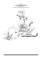
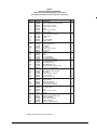
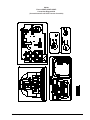
Control Housing Assembly Drawing ................................................................................................. 44
Parts List ....................................................................................................................................... 45
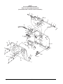
Rear Cover Assembly Drawing ......................................................................................................... 46
Parts List ....................................................................................................................................... 47
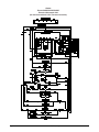
Electrical Schematic .......................................................................................................................... 48
Connection Diagram ......................................................................................................................... 49
Components for machines with 40089A Traverse Controller ......................................................................... 51-57
Control Housing Assembly Drawing ................................................................................................. 52
Parts List ....................................................................................................................................... 53
Rear Cover Assembly Drawing ......................................................................................................... 54
Parts List ....................................................................................................................................... 55
Electrical Schematic .......................................................................................................................... 56
Connection Diagram .........................................................................................................................
57
®
Page
-2-
Clarke
Operator's Manual -Encore S28XP/S33XP/S38XP
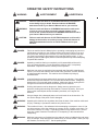
OPERATOR SAFETY INSTRUCTIONS
WARNING
AVERTISSEMENT
ADVERTENCIA
DANGER:
Failure to read and observe all DANGER statements could result in
severe bodily injury or death. Read and observe all DANGER
statements found in your Owner's Manual and on your machine.
WARNING:
Failure to read and observe all WARNING statements could result
in injury to you or to other personnel; property damage could
occur as well. Read and observe all WARNING statements found in
your Owner's Manual and on your machine.
CAUTION:
Failure to read and observe all CAUTION statements could result in
damage to the machine or to other property. Read and observe all
CAUTION statements found in our Owner's Manual and on your
machine.
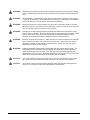
DANGER:
Failure to read the Owner's Manual prior to operating or attempting any service or
maintenance procedure to your Clarke machine could result in injury to you or to
other personnel; damage to the machine or to other property could occur as well.
You must have training in the operation of this machine before using it. If your
operator(s) cannot read English, have this manual explained fully before attempting
to operate this machine.
DANGER:
Operating a machine that is not completely or fully assembled could result in
injury or property damage. Do not operate this machine until it is completely
assembled. Inspect the machine carefully before operation.
DANGER:
Machines can cause an explosion when operated near flammable materials and
vapors. Do not use this machine with or near fuels, grain dust, solvents, thinners,
or other flammable materials. This machine is not suitable for picking up
hazardous dust.
DANGER:
Lead acid batteries generate gases which can cause an explosion. Keep sparks
and flames away from batteries. Do not smoke around the machine. Charge the
batteries only in an area with good ventilation. Make sure that you unplug the AC
charger from the wall outlet before diconnecting from the machine.
DANGER:
Working with batteries can be dangerous! Always wear eye protection and
protective clothing when working near batteries. Remove all jewelry. Do not put
tools or other metal objects across the battery terminals, or the tops of the
batteries.
DANGER:
Using a charger with a damaged power cord could result in an electrocution. Do
not use the charger if the power cord is damaged.
WARNING:
Operating this machine from anywhere other than the back of the machine could result
in injury or damage. Operate this machine only from the rear.
WARNING:
This machine is heavy. Get assistance before attempting to transport or move it. Use
two able persons to move the machine on a ramp or incline. Always move slowly. Do
not turn the machine on a ramp. If operating machine on a gradient over 2%, do not
stop, turn or park. Read the "Procedures For Transporting" in this manual before
transporting.
WARNING:
Machines can topple over if guided over the edges of stairs or loading docks and cause
injury or damage. Stop and leave this machine only on a level surface. When you stop
the machine, turn the key "OFF". Set the parking brake.
Clarke®
Operator's Manual - Encore S28XP/S33XP/S38XP
-3-
Page
WARNING:
Maintenance and repairs performed by unauthorized personnel could result in damage
or injury. Maintenance and repairs must be performed by authorized Clarke personnel
only.
WARNING:
Any alterations or modifications of this machine could result in damage to the machine
or injury to the operator or other bystanders. Alterations or modifications not authorized
by the manufacturer voids any and all warranties and liabilities.
WARNING:
Electrical components of this machine can "short-out" if exposed to water or moisture.
Keep the electrical components of the machine dry. Wipe the machine down after each
use. For storage, keep the machine in a dry building.
WARNING:
Operating a machine without observing all labels and instructional information could
result in injury or damage. Read all machine labels before attempting to operate. Make
sure all of the labels and instructional information are attached or fastened to the
machine. Get replacement labels and plates from your Clarke distributor.
WARNING:
Wet floor surfaces can be slippery. Water solutions or cleaning materials used with this
type of machine can leave wet areas on the floor surface. These areas can cause a
dangerous condition for the operator or other persons. Always put "Caution" signs
around/near the area you are cleaning.
WARNING:
Improper discharge of waste water may damage the environment and be illegal. The
United States Environmental Protection Agency has established certain regulations
regarding discharge of waste water. Also, city and state regulations regarding this
discharge may be in your area. Understand and follow the regulations in your area. Be
aware of the environmental hazards of chemicals that you dispose.
CAUTION:
Use of this machine to move other objects or to climb on could result in injury or damage. Do not use this machine as a step or furniture. Do not ride on this machine.
CAUTION:
Your machine warranty will be voided if anything other than genuine Clarke parts are
used on your machine. Always use Clarke parts for replacement.
-4-
Clarke®
Operator's Manual -Encore S28XP/S33XP/S38XP
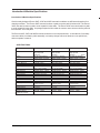
Introduction & Machine Specifications
Introduction & Machine Specifications
Clarke’s newly designed Encore 38XP, 33XP and 28XP automatic scrubbers are efficient and superior floor
cleaning machines. The Encore 38XP uses two brushes or pads to scrub a path 38 inches wide. The Encore
33XP uses two brushes or pads to scrub a path 33 inches wide. The Encore 28XP uses two brushes or pads
to scrub a path 28 inches wide. A squeegee wipes the floor while the vacuum motor removes the dirty solution
from the floor - all in one pass.
The Encore 38XP, 33XP and 28XP automatic scrubbers come complete with six - 6 volt batteries, five battery
connector cables, one battery cable assembly, one battery charger, either two brushes or two pad drivers,
and one operator’s manual.
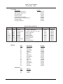
SPECIFICATIONS:
Model
S38XP -00691A
S33XP - 00671A
S28 - 00651A
Motor, Vac
1 HP (.67kw) three
stage tangential
discharge
36 volt (6-6V batteries)
250AH, 330AH, or 370AH
30 gallon (114 liter)
30 gallon (114 liter)
1 hp PM (.74kw)
.50 hp PM (.37kw)
19 inch (48cm)
w/.5" (1.5cm) overlap
200 rpm
Variable 150 lbs. - 200 lbs.
Variable to 230 ft./min.
Variable to 180 ft./min.
36V, 25A, 115V/60hz
66 inches (168cm)
28 inches (71cm)
44 inches (112cm)
42,000 sq ft/hr
(3,901 sq. m/hr)
37.5 inch (95.3cm)
6° Incline
1038 lbs. 471kg
1341 lbs. 608kg
1HP (.67kw) three
stage tagential
discharge
36 volt (6-6V batteries)
250AH, 330AH, or 370AH
30 gallon (114 liter)
30 gallon (114 liter)
.75 hp PM (.56kw)
.50 hp PM (.37kw)
17 inch (43cm)
w/1" (3 cm) overlap
200 rpm
Variable 150 lbs. - 200 lbs.
Variable to 230 ft./min.
Variable to 180 ft./min.
36V, 25A, 115V/60hz
63 inches (160cm)
28 inches (71 cm)
44 inches (112 cm)
35,000 sq ft/hr
(3,252 sq. m/hr)
33 inch (84cm)
6° Incline
1028 lbs. 467kg
1331 lbs. 604kg
1HP (.67kw) three
stage tagential
discharge
Power
36 volt (6-6V batteries)
250AH, 330AH, or 370AH
30 gallon (114 liter)
30 gallon (114 liter)
.75 hp PM (.56kw)
.50 hp PM (.37kw)
14 inch (36cm)
w/.5" (1.5 cm) overlap
200 rpm
Variable 150 lbs. - 200 lbs.
Variable to 230 ft./min.
Variable to 180 ft./min.
36V, 25A, 115V/60hz
62.5 inches (159cm)
28 inches (71 cm)
44 inches (112 cm)
29,7000 sq ft./hr
(2,750 sq ft./hr)
28, inch (70cm)
6° Incline
1018 lbs. 462kg
1321 lbs. 599kg
Supply
Solution Tank
Recovery Tank
Motors, Brush (2)
Motor Traction
Brushes (2)
Brush Speed
Brush Pressure
Speed, Forward
Speed, Reverse
Charger
Length
Width - Machine
Height
Cleaning Rate
Cleaning Swath
Grade Cleaning
Weight w/Batteries (330AH)
Shipping Weight
w/batteries (330AH)
Clarke®
Operator's Manual - Encore S28XP/S33XP/S38XP
-5-
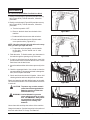
PROCEDURES FOR TRANSPORTING
How To Put The Machine In A Van Or Truck
WARNING:
The machine is heavy. Make sure you use two able persons to assist
the machine in climbing the ramp.
1. Make sure the loading ramp is at least eight (8) feet long, and strong enough to support the machine.
2. Make sure the ramp is clean and dry.
3. Put the ramp in position.
4. Remove squeegee assembly, brush housings, & brushes or pad drivers before loading.
5. Turn key switch "ON".
6. Align the machine on a level surface ten (10) feet in front of the ramp.
7. Put the traverse speed switch in the "HI" position.
8. Push the control handles toward the machine all the way.
9. Push the machine to the top of the ramp.
10. Turn the key switch "OFF".
11. Fasten the machine to the vehicle.
How To Remove The Machine From A Van Or Truck
1. Make sure there are no obstructions in the area.
2. Make sure the unloading ramp is at least eight (8) feet long and strong enough to support the machine.
3. Make sure the ramp is clean and dry.
4. Put the ramp in position.
5. Unfasten the machine.
WARNING:
The machine is heavy. Make sure you use two able persons to assist in
moving the machine down the ramp.
6. Turn the key switch "ON".
7. Carefully and slowly, pull the machine to the top of the ramp.
8. Put the traverse speed switch in the "HI" position.
9. As the machine begins to travel down the ramp, push the control handles toward the machine to
maintain a slow downward speed.
10. Replace squeegee assembly, brush housings, & brushes or pad drivers after the machine is unloaded
and ready to use.
Page
-6-
Clarke®
Operator's Manual -Encore S28XP/S33XP/S38XP
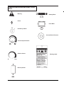
SYMBOLS USED ON ENCORE S38XP, S33XP,
S28XP
Warning
Battery Meter
Power
Hour Meter
On/Off Key Switch
Increase Brush Pressure
Traverse Speed Control
Solution Contro
Warning Label
Brush Up/Down
Clarke®
Operator's Manual - Encore S28XP/S33XP/S38XP
-7-
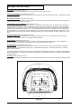
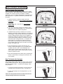
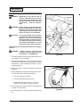
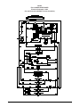
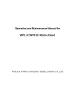
MACHINE CONTROL PANEL
Key Switch (See Figure #1, Item "A")
The key switch turns "ON" the power to the control panel. "0" is "OFF" and "1" is "on".
Traverse Speed Switch (See Figure #1, Item "B")
The speed control varies from low to high speed. To increase the speed, turn the knob to the right. To decrease the speed,
turn the knob to the left.
Brush Up/Down Switch (See Figure #1, Item "C")
The brush switch has two positions: "Up" positions the brushes up; "Down" positions the brushes on the floor. The brush
motors start when the brushes are down.
Increase Brush Pressure Switch (See Figure #1, Item L)
This switch is used to increase the brush pressure. Increased brush pressure may be required when stripping or
cleaning heavily soiled floors. To increase brush pressure, first lower the brushes by pressing the brush up/down
switch (Item "C") to the down position. This will lower the brushes to the normal scrub position. To increase brush
pressure, press and hold the switch (Item "L") until the desired brush pressure is reached or the brush deck stops
moving downward. To reposition the brush pressure to normal scrub, press the brush up/down switch (Item "C") to
the up position and after the brush deck is completely raised, then return the switch to the down position for normal
scrub.
Solution Control Knob (See Figure #1, Item "D")
The solution control knob regulates the flow of cleaning solution to the floor. To increase the flow turn the knob
clockwise. To decrease the flow, turn the knob counter-clockwise.
Control Handle (See Figure #1, Item "E")
The control handle is located at the rear of the machine. It controls the direction of the machine. Push forward to go
forward. (See Figure #3, page 10). Pull back to move in reverse. (See Figure #4, page 10).
Circuit Breakers (See Figure #1, Item "F"-"J")
The circuit breaker reset buttons are located on the rear cover, below the control handle. The breakers are located as
follows: Item F & G - Brush Motors (35A); Item H - Traverse Motor (30A); Item I - Vac Motor (25A); Item J - Actuator
Motor, Brush Head (5A)
If a circuit breaker trips, determine which motor is not operating and turn the key switch "OFF". Wait five minutes and push
the reset button back in. Turn the key switch "ON", and try again. An authorized service person should be contacted if the
breaker trips again.
Hour Meter (See Figure #1, Item "K")
The hour meter indicates the number of hours the machine has operated. It runs only when the machine is moving forward
or reverse.
E
C
D
B
L
A
K
J
I
H
G
F
Figure #1
Page
-8-
Clarke®
Operator's Manual -Encore S28XP/S33XP/S38XP
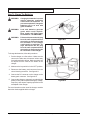
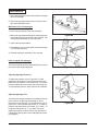
MACHINE CONTROLS & FEATURES
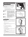
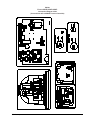
Squeegee Lift Handle See Figure #5a, 5b, & 5c.
The squeegee lift handle is located below the control handles
on the right side. It is used to raise or lower the squeegee.
The vac motor is turned on when the handle is lowered. (S38,
S33 & S28 models only).
Parking Brake (Optional)See Figure #6.
The parking brake prevents movement of the machine. The
brake is located on the left hand side of the transaxle motor.
Turn the key switch off or disconnect the power to the battery
to apply the brake.
There is a mechanical lever located on the brake. This lever
is an override. To manually release the brake, rotate the
lever toward the rear of machine (counter clockwise). To
return the brake to normal or to apply the brake, rotate the
lever towards the front of the machine (clockwise). NOTE:
If the lever is left in the override position, the brake will
not function with the key switch, and the machine will
not operate.
Figure #5a
CAUTION: Do not activate the brake while the machine
is moving.
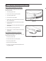
Float Shut Off See Figure #7.
The shut-off switch for the vac motor is located in the recovery tank. It automatically turns off the vac motor when the
recovery tank is full.
Figure #5b
Figure #6
Figure #5c
Figure #7
Clarke®
Operator's Manual - Encore S28XP/S33XP/S38XP
-9-
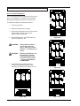
HOW TO PREPARE THE MACHINE FOR OPERATION
38720B
The 38, 33 and 28 Encore machines use six 6-volt or
three 12-volt batteries. The batteries are located in
the battery compartment under the recovery tank.
38720B
38722B
How To Install The Batteries
To Install the batteries, follow this procedure:
1. Turn key switch off.
2. Make sure both tanks are empty.
38722B
3. Disconnect the hoses from the recovery tank
(upper tank) & unplug the vac motor.
Remove the recovery tank.
38720B
38722B
Figure #8a
4. Place the batteries in the solution tank as
shown in figures 8a - 8d.
WARNING:
Working with batteries can
be dangerous. Always
wear eye protection and
protective clothing when
working near batteries.
NO SMOKING!
38722B
38720B
38722B
Figure #8b
38722B
38720B
38720B
5. Connect the battery cables between
batteries and install long battery cable
assembly as indicated. See figure 8a - 8d.
38720B
38722B
Figure #8d
Page
-10-
38722B
Lifting batteries without
help could result in an
injury. Get help to lift the
batteries. The batteries are
heavy.
38720B
WARNING:
38720B
38722B
Figure #8c
Clarke®
Operator's Manual -Encore S28XP/S33XP/S38XP
HOW TO PREPARE THE MACHINE FOR OPERATION
6. Join the connector from the battery pack to
the connector on the control panel. See
figure #9.
7. Install the tank, reconnecting hoses and
replace the two screws attaching the
solution tank to the rear of the frame.
NOTE: Charge the batteries before using the
machine.
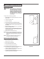
Battery Maintenance
Figure #9
The electrical power to operate the machine comes from
the storage batteries. Storage batteries need preventive
maintenance.
WARNING:
Working with batteries can be dangerous. Always wear eye protection and protective clothing when
working near batteries.
NO SMOKING!
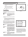
To maintain the batteries in good condition, follow these
instructions:
1. Keep the electrolyte at the correct level. The correct
level is between 1/4" below the bottom of the tube in
each cell and above the tops of the plates. Check the
level of the electrolyte each time you charge the
batteries. See figure #10.
NOTE: Check the level of electrolyte prior to charging the
batteries. Be sure the plates in each cell are covered with
electrolyte . Do not top off the cells prior to charging the
battery. Electrolyte expands during charging. As a result,
the electrolyte could overflow from the cells. Always top
off the cells with distilled water after charging.
CAUTION:
Irreversible damage will occur to
the batteries if the electrolyte level
does not cover the plates. Keep the
electrolyte at the correct level.
CAUTION:
Machine damage and discharge
across the tops of the batteries can
occur if the batteries are filled
above the bottom of the tube in
each cell. Do not fill the batteries up
to the bottom of the tube in each
cell. Wipe any acid from the machine or the tops of the batteries.
Never add acid to a battery after
installation.
CAUTION:
Clarke®
Tap water may contain contaminants that will damage batteries.
Batteries must be re-filled with distilled water only.
Operator's Manual - Encore S28XP/S33XP/S38XP
Correct fill level
Figure #10
2.
Keep the tops of the batteries clean and dry.
Keep the terminals and connectors clean. To
clean the top of the batteries, use a damp cloth
with a weak solution of ammonia or bicarbonate
of soda solution. To clean the terminals and
connectors, use a terminal and connector cleaning tool. Do not allow ammonia or bicarbonate of
soda to get into batteries.
3.
Keep the batteries charged.
- 11 -
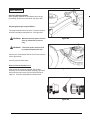
HOW TO PREPARE THE MACHINE FOR OPERATION
How To Charge The Batteries
WARNING:
Charging the batteries in an area
without adequate ventilation
could result in an explosion. To
prevent an explosion, charge the
batteries only in an area with
good ventilation.
WARNING:
Lead acid batteries generate
gases which could explode.
Keep sparks and flames away
from batteries. NO SMOKING!
WARNING:
Failure to disconnect the AC plug
from the wall receptacle before
connecting or disconnecting the
DC connector on the charger
could result in an explosion. Always disconnect the AC plug
from the wall receptacle before
connecting or disconnecting the
DC connector on the charger.
Figure # 11
To charge the batteries, follow this procedure:
1. Put the charger on a flat surface. Make sure the
vents on the sides are at least two inches away
from walls and other objects. Make sure there are
no objects near the vents on the bottom of the
charger.
2. Make sure the key switch is in the “OFF” position.
3. Disconnect the battery pack connector from the
control housing connector. See figure #11.
4. Connect the DC connector on the charger to the
battery pack connector. See figure #12.
5. Connect the charger to a properly grounded single
phase (3-wire) wall receptacle having the voltage,
frequency, and ampere capacity specified on the
nameplate of the charger.
Figure #12
For more instruction on the use of the charger, read the
instruction book supplied with the charger.
Page
-12-
Clarke®
Operator's Manual -Encore S28XP/S33XP/S38XP
HOW TO PREPARE THE MACHINE FOR OPERATION
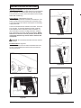
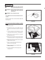
How To Install The Brushes Or Pad Drivers
To install the brushes or pad drivers on the machine,
follow this procedure:
1. Turn the key switch "ON".
2. Put the brush switch in the "UP" position.
3. Turn the key switch "OFF".
4. Go to the front of the machine.
5. Unlatch right and left brush housings and remove
them. See figure #13.
Figure #13
6. Put a brush or pad driver under the brush motor plate.
See figure #14.
7. Align the lugs on the motor gimbal with the slots in the
brush gimbal.
8. Pull the brush up until the gimbal locks.
9.
Repeat steps 6, 7, and 8 to install the second brush
or pad driver.
How To Remove The Brushes Or Pad Drivers
To remove the brushes or pad drivers from the
machine,follow this procedure:
1. Turn the key switch "ON".
Figure #14
2. Put the brush switch in the "UP" position.
3. Turn the key switch "OFF".
4. Go to the front of the machine.
5. Push down on two sides of the brush or pad driver until
the gimbals release.
Clarke®
Operator's Manual - Encore S28XP/S33XP/S38XP
- 13 -
HOW TO OPERATE THE MACHINE
How To Operate The Scrub Deck
Brushes or pads are used along with a solution mix to agitate
and scrub the floor. Many different types of brushes or pads are
available (see accessory section) for different scrubbing
applications. See your Clarke representative for proper brush or
pad requirements. To operate the brushes or pads follow this
procedure:
A
1. Install the brushes or pads and replace the brush
housings. See section on How To Install the Brushes Or
Pad Drviers.
2. Fill the solution tank. See section on How To Fill The
Solution Tank.
Figure #15
3. Lower the brush deck by pressing the Up/Down brush
switch to the down position (figure 15, A). This will place
the brush deck in the normal scrub position.
4. If additional brush pressure is desired, such as when
stripping or cleaning a heavily soiled floor, more pressure
can be applied. After the brush deck has been lowered to
the floor, additional brush pressure can be applied by
pressing and holding the jog button switch (figure 16, B)
until the desired brush pressure is reached or until the
brush deck stops moving downward. To reposition the
brush pressure to normal scrub, press the brush up/
down switch to the up position and after the brush deck
has completely raised, then return the switch to the down
position for normal scrub.
C
B
Figure #16
5. The brushes/pads and solution will start when the
traverse control handle (figure 16, C) is pushed forward
or pulled to the rear. Note: The brushes/pads and
solution will only operate when the brush deck is in the
down position and the traverse control handle is pushed
forward or pulled to the rear.
6. Stop the brushes/pads and solution flow by releasing the
traverse control handle, or raising the brush deck to the
full up position.
How To Operate the Squeegee
("S Class" models only)
The squeegee wipes the floor while the vacuum motor removes
the dirty solution from the floor. Use your right hand to lower or
raise the squeegee handle. To operate the squeegee, follow
this procedure:
Figure #17
1. To lower the squeegee and start the vac motor move the
squeegee lever to the right and down. See figure #17.
2. To raise the squeegee, lift the squeegee lever up. See
figure #18.
Note: The center position lets the vac motor continue to run
with the squeegee off the floor to avoid drips.
Figure #18
Page
-14-
Clarke®
Operator's Manual -Encore S28XP/S33XP/S38XP
HOW TO OPERATE THE MACHINE (cont.)
How to Fill The Solution Tank
CAUTION: Make sure water or solution does not
enter the opening for the vacuum motor ,See figure #19.
The solution tank lid is at the front. To fill the solution tank
follow this procedure:
1. Remove the solution tank lid. See figure #20
2. Fill the solution tank with water.
3. Add a cleaning chemical to the water. for the correct
amount, follow the directions shown on the container.
WARNING:
WARNING:
WARNING:
Water solutions or cleaning materials
used with this type of machine can leave
wet areas on the floor surface. These
areas can cause a dangerous condition
for the operator or other persons. Always
put CAUTION signs near the area you are
cleaning.
Machines can ignite flammable materials
and vapors. Do not use with or near
flammables such as gasoline, grain
dust, solvents, and thinners. Only use a
cleaning concentration recommended by
the chemical manufacturer.
Clarke recommends a maximum water
temperature of 120°F(49°C)
Figure # 19
Figure # 20
4. Replace the solution tank lid.
How To Clean A Floor
NOTE: Put the machine in the slow traverse speed. Use the
machine in an area that has no furniture and objects until you
can do the following:
1.
Move the machine in a straight direction, forward and backward.
2.
Stop the machine safely.
3.
Move the machine in a straight direction after you turn the
machine.
To move the machine, follow this procedure:
1.
Turn the key switch “ON” position.
2.
Put the brush switch in the "UP" position.
Figure # 21
3. Raise the squeegee.
4. To go forward, push the control handles toward the
machine. See figure #21.
5. To stop the machine, put the handles in the center
position.
6. To go backward, pull the handles away from the machine. See figure #22.
7. To turn the machine, push the rear of the machine to the
side.
8. When you stop the machine, turn the key switch "OFF".
Clarke®
Operator's Manual - Encore S28XP/S33XP/S38XP
Figure # 22
- 15 -
HOW TO OPERATE THE MACHINE (cont.)
HOW TO CLEAN A FLOOR
WARNING: Water solutions or cleaning materials used with this type of machine
can leave wet areas on the floor
surfaces. These areas can cause a
dangerous condition for the operator or other persons. Always put
CAUTION signs near the area you
are cleaning.
3
To clean a floor, follow this procedure:
1. Put the water and a cleaning chemical in the clean
solution tank.
2. Turn the key switch "ON".
4
3. Lower the squeegee.
4. Put the brush switch in the "DOWN" position.
5. Turn the solution knob to the right to activate the flow
of solution. Adjust the flow of clean solution to the
flow desired.
2
6. Move the machine across the floor in the forward
direction. See figure #23 (1).
7. When the machine is one machine length from the
end of the area to be cleaned (figure #23 (2)), rotate the
solution knob to the left.
8.
Make a 1800 turn. See figure #23 (3).
NOTE: When you make more passes across the floor, let
the brushes clean approximately 2 inches of the
area already cleaned by the brushes. See figure
#23 (4).
NOTE: During most cleaning procedures, apply and
remove the solution in one operation.
HOW TO CLEAN A VERY DIRTY FLOOR
To clean a very dirty floor, follow this procedure:
1. Apply solution to the floor.
2. Do not lower the squeegee.
3. Do not activate the vacuum motor.
4. Lower the brushes and scrub the floor.
Figure #23
NOTE: Additional brush pressure may be applied (see
section on How To Operate Scrub Deck).
5. Leave the solution on the floor long enough for the
solution to begin cleaning the floor.
6. Scrub the floor again with additional solution, picking
up all the solution with the squeegee
Page
-16-
Clarke®
Operator's Manual -Encore S28XP/S33XP/S38XP
MAINTENANCE
WARNING: Maintenance and repairs must be
done by authorized personnel only.
WARNING: Always empty the solution tank and
recovery tank before doing any
maintenance.
WARNING: Keep all fasteners tight.
These Maintenance Procedures Must Be Done Every Day
Keep the machine clean, it will need fewer repairs and
have longer life.
Figure #24
Do These Procedures When You Begin Your Work
Period
1. Turn off key switch.
2. Disconnect the plug on the charger from the
connector on the back of the machine. See figure
#24.
3. Join the connector from the batteries (1) to the
control panel cable connection. See figure #24.
4. Make sure the recovery tank lid is on correctly.
See figure #25, Item A.
5. Make sure the Screen filter over the vacuum motor
is clean and in position. See figure #26, Item B.
Figure #25
6. Make sure the valves on the drain hoses are clean.
Tightly close the valves.
7. Make sure brush housings and skirts are in
position on the brush head.
8. Make sure the brushes are in position and
installed correctly
9. Check the installation of the squeegee and
squeegee hose.
Figure #26
Clarke®
Operator's Manual - Encore S28XP/S33XP/S38XP
- 17 -
MAINTENANCE
Do These Procedures When You End Your Work
1. Drain the solution tank (Figure #27a) and the recovery
tank (Figure #27b). To drain the tanks , follow this
procedure:
2. Drain the solution tank (Figure #27a) and the recovery
tank (Figure #27b). To drain the tanks , follow this
procedure:
25
a. Turn the key switch “OFF”.
Figure #27a
b. Remove the drain hose from the back of the
machine.
c. Put the end of the hose over a drain or bucket.
d. Turn the valve handle to the left. Pull the handle
out to open the drain. (Figure #27c)
NOTE: Have the opening in the side of the valve away
from you when you open the valve.
e. To open the valve completely, turn the handle
to the right. Pull the handle out of valve.
(Figure #27d)
2. Flush the tanks. To flush the tanks, put clean water in
the tank through the opening on top of the tank.
Figure #27b
3. If a tank or drain hose has an obstruction, use a high
pressure water hose to flush the tank or hose. Put the
water hose into the drain hose.
4. Leave the tanks and the drain valves open to dry in the
air.
5. Check the squeegee blade. Use a cloth to clean the
squeegee blade. If the squeegee blade is damaged or
worn, turn or replace the blade.
6. Check and clean the solution lid gasket. Use a mild
cleaning solution and rinse the parts in clean water.
Check the batteries and add distilled water as needed.
The correct level is within 1/4 inch of the bottom of the tube
in each cell.
Figure #27c
CAUTION: Tap water may contain contaminants that will damage batteries.
Batteries must be re-filled with
distilled water only.
WARNING: Lead acid batteries generate
gases which can cause an explosion. NO SMOKING. Always wear
eye protection and protective
clothing when working near
batteries.
Use a clean cloth and wipe the surface of the machine.
Figure #27d
Charge the batteries. See the instruction in the section of
this book called “How To Charge The Batteries”.
Page
-18-
Clarke®
Operator's Manual -Encore S28XP/S33XP/S38XP
MAINTENANCE
These Maintenance Procedures Must Be Done Every
Week:
WARNING: Maintenance and repairs must be
done by authorized personnel only.
Always empty the solution tank and
the recovery tank before doing any
maintenance. Keep all fasteners
tight.
WARNING: Always wear eye protection and protective clothing when working near
batteries. Do not put tools or other
metal objects across the battery terminals or the tops of the batteries.
CAUTION: To prevent damage to the machine,
and discharge across the tops of the
batteries, do not fill the batteries
above the bottom of the tube in each
cell. Wipe any acid from the machine
or the tops of the batteries. Do not
add acid to battery after installation.
NOTE: Always turn off key switch before servicing the
machine.
WARNING:
Always wear eye protection and
protective clothing when working
near batteries. NO SMOKING!
Figure #28
1. To inspect batteries, tip up recovery tank until it locks
in up position. See Figure #28.
2. Disconnect the batteries. Use a cloth and a solution
of ammonia or bicarbonate of soda to wipe the top of
the batteries. Clean the battery terminals. Reconnect the batteries.
3. Check the hoses for leaks, obstructions and other
damages.
4. Check and clean the filter screen in the solution hose.
To clean the screen, follow this procedure:
a. Turn the connector to the left.
b. Remove and clean the filter screen.
c. Install the filter screen in the hose. Turn the
connector to the right to connect the hose.
5. Use a grease gun to lubricate the drive wheel and the
casters. See figure #29.
Figure #29
6. Check tire pressure. Tire pressure should be about 50
psi.
Clarke®
Operator's Manual - Encore S28XP/S33XP/S38XP
- 19 -
MAINTENANCE
7. Check the squeegee and the scrub brushes or the pad
drivers for damage.
8. Check the squeegee and the vacuum hose for dam
age, leaks and obstructions.
Maintenance For The Squeegee
To remove the squeegee, follow this procedure:
1. Remove the squeegee assembly by loosening the two
knobs that attach the squeegee to the machine. Pull
the squeegee assembly off. See figure #30.
Figure #30
2. Inspect the squeegee blade.
3. If the blade is worn, turn the blade so that a new edge
is in the wiping position.
4. Reinstall squeegee assembly on the machine.
How To Adjust The Squeegee
The following adjustments are set at the factory, however
they may require slight adjustment.
Figure #31
Adjusting Squeegee Pressure:
To adjust the pressure, refer to Figure #31. Proper
adjustment will produce a uniform flare along the rear
blade when the machine is moved forward. To increase
pressure, tighten the nuts on each side of the swing arm.
To decrease the pressure, loosen the nuts on each side.
Adjusting Squeegee Tilt:
The tilt of the squeegee causes the rear blade to raise up
in the center or on the ends, depending on which
direction the tilt is changed. For tilt adjustment, refer to
figure # 32. Loosen left and right screw "X". In order to
bring the rear blade down in the center, tip "Y" down. To
bring both ends down, tip "Y" up. Make very small
adjustments and try it until a uniform flare is achieved.
Changing the tilt may also require readjusting the squeegee pressure.
Page
-20-
Figure #32
Clarke®
Operator's Manual -Encore S28XP/S33XP/S38XP
MAINTENANCE
Adjusting Squeegee Blades
When properly installed the front blade should be approximately .06 above the rear blade. See figure #33.
Adjusting Squeegee Support Wheels:
.12
The support wheels should be set at .12 above the floor
with the rear blade touching the floor. See figure #33.
WARNING: Maintenance and repairs must be
done by authorized personnel
only .
WARNING:
Figure #33
Electrical repairs must be done
by authorized personnel only.
Consult your Clarke Authorized Service Person to do the
service procedures.
Use only genuine Clarke parts.
How to Clean the Solution Line
If the solution line becomes clogged, pull the filter
assembly out from behind the brush housing (Figure #34
and remove the filter screen (Figure # 35) and clean or
replace it. Push filter assembly back inside frame.
Figure #34
Figure #35
Clarke®
Operator's Manual - Encore S28XP/S33XP/S38XP
- 21 -
Clarke® Encore 28/33/38
Accessories - 6/02
ACCESSORIES
Description
Power Wand System Kit
ESP Recycle System Kit
Soft Caster Asm.
Clarke Care Kit
Drive Wheel, Foam Filled
Imperial Electric Parking Brake Kit
Accessory Bag
Poly Dur Protectant
Machine
No.
38
38
38
28, 33
28, 33
28, 33
28, 33
28, 33
28, 33
Part No.
10674A
10675A
52127A
14607A
59955A
10684A
30070A
50478A
Optional Squeegee Blades
Material
Blade
Type
Front
Front
Rear
Rear
Rear
Rear
Front
Front
Front
Optional
Optional-Grout
Optional
Optional
Optional
Optional
Optional
Optional-Grout
Optional
Urethane, Ribbed (60)
Urethane, Notched, 1/16" (80)
Nitrile, Solid (40)
Gum Rubber
Nitrile, Solid
Orange, Ribbed
Natural, Ribbed
Slit Grout
Orange, Ribbed
Length
Part
46.00"
46.00"
48.00"
43.50"
43.50"
43.50"
40.25"
40.25"
40.25"
30954A
30959A
30939A
30069A
30082A
30086A
30091A
30080A
30084A
Brushes:
Size
17"
17"
17"
17"
17"
14"
14"
14"
14"
14"
19"
19"
19"
19"
19"
Pad Drivers:
Size
19"
17"
14"
Page
-22-
Description
Poly
Grit-Heavy
Grit-Medium
Grit-Lite
Soft Nylon
Poly
Grit-Heavy
Grit-Medium
Grit-Lite
Soft Nylon
Poly
Grit-Heavy
Grit-Medium
Grit-Lite
Soft Nylon
Part No.
11424B
11425B
11430B
10384A
11428B
11427B
11426B
11431B
10383A
11429B
11434B
11433B
11432B
10385A
11435B
Part No.
17524B
17520C
17521C
Clarke®
Operator's Manual -Encore S28XP/S33XP/S38XP
Encore
S28XP, S33XP, S38XP
Section II
Parts and Service Manual
(70657A)
U.S. Patent No. 6,105,192; No. 5,383,251; No. 6,557,207
Clarke®
Operator's Manual - Encore S28XP/S33XP/S38XP
- 23 -
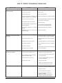
HOW TO CORRECT PROBLEMS IN THE MACHINE
PROBLEM
The machine does not remove all the
water from the floor.
The batteries do not give the normal
running time.
The cleaning is not even.
CAUSE
ACTION
The squeegee is up
Lower the squeegee.
The vacuum tank is full.
Drain the tank.
The screen filter is dirty.
Clean the screen filter.
There is an obstruction or damage in the
squeegee, squeegee hose or standpipe.
Remove the obstruction or repair the damage.
The vacuum motor is not running.
Check for tripped breaker. Have an authorized
service person make repairs.
The squeegee hose is disconnected.
Connect the hose.
The squeegee blade is damaged, worn, or
incorrectly installed.
Turn or replace the squeegee blade.
Correctly install the squeegee blade.
The squeegee pressure is not correctly
adjusted.
Adjust the pressure of the squeegee.
The gaskets on the cover of the recovery
tank are damaged.
Replace the gaskets.
The battery terminals are dirty or damaged.
Clean the terminals and connectors. Replace
the damaged cables. Charge the batteries.
The electrolyte level is too low.
Add distilled water to each cell and charge the
batteries.
The batteries are not fully charged.
Charge the batteries for a full 16 hour charge.
The charger is damaged.
Have an authorized service person repair the
charger.
The battery is defective.
Check voltage of each cell while discharging.
The batteries are disconnected.
Connect the batteries.
The scrub brushes or pads are worn.
Replace the scrub brushes or pads.
There is damage to the brush assembly,
casters or the solution valve.
Have an authorized service person make
the needed repairs.
The brush motors are not running
Check for tripped breaker, reset. Check
for loose connections.
The solution level is low.
Fill the solution tank.
NOTE: If the motors continue to stop
consult an authorized service person.
The machine does not run.
Reset the circuit breaker.
Check wire connection to traverse motor.
The machine loses power.
Replace the fuses.
Check the batteries connections.
Check parking brake overide lever
position (if installed)
NOTE: If the motors continue to stop,
consult an authorized service person.
Page
-24-
Clarke®
Operator's Manual -Encore S28XP/S33XP/S38XP
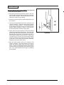
MAINTENANCE
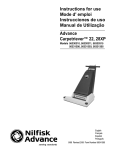
Adjusting Brush Head Position Switch: (See figure 34)
1.Turn "ON" the key switch.
2. Start with the brush head up/down switch in the "Up"
position and the brush pressure knob set to minimum,
fully counter clockwise. This should cause the brush
head to be in the full "Up" position.
3. Install the proper brushes or pads and pad drivers for
the machine.
4. Leave the brush pressure knob set to minimum, fully
counter clockwise. Switch the brush head up/down
switch to the "Down" position. This should cause the
brush head to travel down to the floor until the brush
position switch (47422A) is closed. At this time the
brush head actuator will stop running down.
5. Check at the front of the machine to see if the brushes
or pads are completely flat on the floor. The screw, that
goes through the brush head actuator tube (69188A),
should be at the top of the 1.25 inch slot in the tube. If
the brushes or pads are not on the floor, or the screw
is not at the top of the slot, the brush position switch
. (47422A) needs to be loosened and moved up or down
in the slot on the switch mount bracket (65972A).
Retighten the brush position switch.
Figure #34
6.Keep the brush pressure knob set to minimum, fully
counter clockwise. The brush head will need to be
raised and lowered again with the brush up/down
switch. Check to see if the adjustment put the brushes
or pads on the floor and kept the screw at the top of the
tube. If no, repeat step #5 until this step is completely
accomplished.
CLARKE
Manual
- Encore
S28/L28/S33/L33/S38/L38
Clarke®Operator's
Operator's
Manual
- Encore
S28XP/S33XP/S38XP
- 25 -
- 25 -
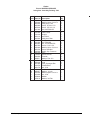
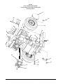
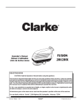
Clarke®
Encore S28XP/S33XP/S38XP
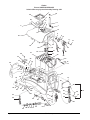
Swing Arm Assembly Drawing 5/04
31
30
2
1
2
7
30
6
3
27
8
32
4
30
16
29
28
9
10
6
15
16 30
11
23
25
24
12
13
18
14
26
17
5 33
19
6
20
22
Page
-26-
21
Clarke®
Operator's Manual -Encore S28XP/S33XP/S38XP
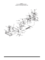
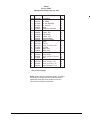
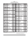
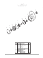
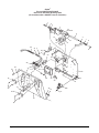
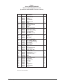
Clarke®
Encore S28XP/S33XP/S38XP
Swing Arm Assembly Drawing 5/04
Ref #
1
2
3
4
5
6
7
8
9
10
11
12
13
14
15
16
17
18
19
20
21
22
23
24
25
26
27
28
29
30
31
32
33
Clarke®
Part No.
57275A
87623A
60452A
86004A
85730A
81104A
38021A
61679A
51613A
920110
60454A
920256
81105A
920296
962798
87624A
80015A
53423A
68016A
170915
64905A
980651
60678C
25201A
35192A
61267A
81217A
920208
980657
87625A
81303A
87026A
87031A
Description
Pulley
Washer, Nylon 1¼x¼x1/8
Swing Arm, Front
Screw, .25-20 x 1.50
Screw, .375-16 x 1¼
Nut, Hex ESNA SS
Strap
Cable, Lower
Bumper
Nut, ESNA
Swing Arm, Rear
Nut, Hex
Nut, ESNA SS
Nut, 10-24 ESNA SS
Screw, 10-24 x .50
Washer, Nylon 1½x¼x1/8
Screw, Shoulder
Spring, Squ. Pressure
Stud
Screw, SS Hex
T Handle
Washer, Flat .312
Pivot Bracket
Knob
Hose, Squeegee Rec.
Tube Bracket
Nut, ½-20
Nut, Hex ¼-20
Washer, ¼ Lock
Washer,Nylon 1¼x¼x1/32
Nut, ¼-28
Washer
Washer, 3/8 Flat
Operator's Manual - Encore S28XP/S33XP/S38XP
Qty
2
2
1
2
1
5
1
1
1
2
1
2
1
1
1
2
1
2
2
2
3
1
1
2
1
1
1
1
1
4
1
4
1
- 27 -
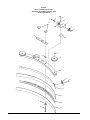
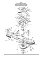
Clarke®
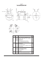
Encore S28XP and S33XP
Squeegee Assembly Drawing 6/04
Drawing #10068A
1
6
2
19
3
4
4
5
18
20
7
17
8
9
10
11
12
13
21
14
16
15
Page
-28-
Clarke®
Operator's Manual -Encore S28XP/S33XP/S38XP
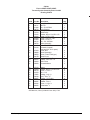
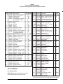
Clarke®
Encore S28XP and S33XP
Squeegee Assembly Parts List 6/04
Ref. #
1
2
3
4
5
6
7
8
9
10
11
12
13
14
15
16
17
18
19
20
21
Clarke®
Part No.
962720
980657
60243A
30049B
81104A
60254A
50958A
30048A
60272A
50835A
930086
60252A
30069A
30058A
30091A
80011A
81301A
34260B
25201A
60358A
80280A
Description
Screw, ¼-20 x ½ Hex SS
Washer, ¼ Lock
Bracket, Squeegee Wheel
Wheel, Squeegee
Nut, ¼-20
Bolt, Shoulder 5/16x 2¼
Ring, 3/8 ID Snap
Wheel, Guide, 4 Inch Diameter
Channel, Squeegee Weldment 39”
Latch, Squeegee Clamp
Rivet, 3/16 x .450 Aluminum
Strap, Clamp, Squeegee Retainer 39”
Blade, Rear, Gum Rubber, 39”
Spacer, Squeegee 39”
Blade, Front Ribbed 39”
Screw, 3/8-16 x 3
Nut, 3/8-16 Jam SS
Gasket
Knob
Shim, Squeegee Wheel
Nut, Squeegee Backup
Operator's Manual - Encore S28XP/S33XP/S38XP
Qty
4
4
2
4
2
2
2
2
1
1
2
1
1
1
1
2
2
1
2
2
2
- 29 -
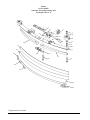
Clarke®
Encore S38XP
Squeegee Assembly Drawing 6/02
Drawing # 16617A - S
1
2
5
7
8
4
6
3
9
26
24
13
25
8
4
10
17
18
11
19
16
14
13
15
12
20
21
22
23
* Apply antiseize to threads
Page
-30-
Clarke®
Operator's Manual -Encore S28XP/S33XP/S38XP
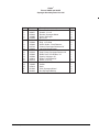
Clarke®
Encore S38XP
Squeegee Assembly Parts List 6/02
Ref #
1
2
3
4
5
6
7
8
9
10
11
12
13
14
15
16
17*
18*
19
20
21
22
23
24
25
26
Part No.
34260B
920110
81104A
81301A
59971A
65975A
920248
980645
59950A
980638
69675A
85610A
38715A
62712A
80011A
37016A
30934A
30935A
62421A
62444A
86004A
170932
55722A
85702A
85816A
54766A
Description
Squeegee Gasket
Nut, ESNA
Nut, Hex ESNA SS
Nut, Jam SS
Wheel
Wheel Mount Bracket
Nut, Jam
Washer, Flat
Guide Wheel
Washer, Lock
Squeegee Base
Screw, PN Phillips
Spacer
Air Duct
Screw, .375-16 x 3.00
Grip Pad
Blade, Inner
Blade, Outer
End Clamp
Clamp, Weld
Screw, .25-20 x 1.50 Hex
Rivet
Squeegee Strap Latch
Screw, .25-20 x 1.75
Screw, .312-18 x 1.75
Insert,Threaded 5/16-24
Qty
1
3
6
4
2
2
2
4
2
2
1
2
2
1
2
1
1
1
1
1
1
2
1
2
2
2
* See accessory page
NOTE: When changing squeegee blades, it might be
necessary to loosen screw #15; install and secure
blades with clamp #20; then retighten screw #15.
This will allow for different thickness.
Clarke®
Operator's Manual - Encore S28XP/S33XP/S38XP
- 31 -
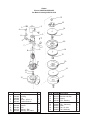
Clarke®
Encore S28XP/S33XP/S38XP
Traverse System Assembly Drawing 6/02
Drawing 19021A
17
24
25
18
26
27
8
16
23
7
10
6
9
15
7
5
23
19
4
28
14
19
3
3
20
29
1
30
2
11
22
21
30
32
13
31
13
12
Page
-32-
Clarke®
Operator's Manual -Encore S28XP/S33XP/S38XP
Clarke®
Encore S28XP/S33XP/S38XP
Traverse System Assembly Parts List 6/02
Drawing 19021A
Ref #
1
2
3
4
5
6
7
8
9
10
11
12
13
14
Part No.
66531A
836711
81104A
69877A
85811A
57275A
87623A
86004A
85703A
85700A
920110
899769
81105A
59116A
Qty
1
1
2
1
2
1
2
1
6
1
2
2
12
1
17
18
19
20
21
85730A
59969A
59955A
32417B
81221A
980614
60230A
65963A
Description
Swing Arm Pin
Hair Pin
Nut, .25-20 ESNA
Swing Bracket
Screw, .312-18 x .75
Cable Pulley
Washer, Nylon 1¼x¼IDx.120
Screw, .25-20 x 1.50
Screw, .375-16 x 1.50
Screw, .25-20 x 1
Nut, .312-16 ESNA
Caster Assembly
Nut, .375-16 ESNA
Transaxle, Imperial
(see page 46, 45 for parts)
Screw, Hex
Wheel Assembly*
Wheel, Foam Filled (opt.)
Wheel Cover
Lug Nut, 50-20 UNF
Washer, Star Lock .25
Main Frame
Transaxle Mount
15
16
22
23
24
25
26
27
28
29
30
31
32
69712A
87625A
80011A
81207A
170883
58419A
980205
69639A
980645
962244
980638
Spacer
Washer, Nylon 1¼x¼IDx3/32
Screw, 3/8-16 x 3
Nut, 3/8-16
Washer, Lock 3/8
Stud, 3/8M x 3/8F
Washer, .25 Fender
Strap, Static
Washer, Flat 3/8
Screw, 3/8-16 x ¾
Lockwasher 3/8
2
2
2
2
2
2
2
1
6
4
4
4
2
2
2
6
3
1
2
*30039A tube, inner (included in item #16) 1 Ref.
Clarke®
Operator's Manual - Encore S28XP/S33XP/S38XP
- 33 -
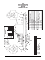
Clarke®
Encore S28XP/S33XP/S38XP
Brush Head Assembly Drawing 6/02
Drawing # 11453A, 11449A, 11452A
2
3
1
4
5
73
36
7
6
13
8
14
15
12
16
17
11
18 12
10
20
18
9
7
30
6
28
29
27 6
20
12
26
9
7
21
24
24
1
22
25
3
23
32
31
68
33
69
70
67
34
68
35
71
37
49
66
27
38
39
38
35
40
18
65
41
61
64
63
49
48
62
59
45
60
52
58
53
51
50
4
45
54
42
47
46
55
-34-
44
43
27
56
Page
72
57
Clarke®
Operator's Manual -Encore S28XP/S33XP/S38XP
Clarke®
Encore S28XP/S33XP/S38XP
Brush Head Assembly Parts List 8/04
Ref #
1
2
3
4
5
6
7
8
9
10
11
12
13
14
15
16
17
18
20
21
22
23
24
25
26
27
28
29
30
Part No.
82501A
60230A
766780
962244
69883A
980608
920056
81105A
920110
60472A
47374A
962980
38708A
42401A
50208A
69188A
85602A
87007A
47422B
63032A
85838A
67705B
920278
980626
980673
81104A
51278A
38723A
53421A
Description
Pin
Main Frame
Hair Pin
Screw, .375-16x.75
Switch Bracket
Washer, #6
Nut, #6-32 ESNA
Nut, .375-16 ESNA
Nut, .312-18 ESNA
Switch Mount
Lever, Switch
Screw, #6-32x1.00 PN
Nylon Spacer
Diode
Actuator & Tube Asm.
Head Pressure Tube
Screw, .25-20 x 3
Washer, Flat .25
Whisker Switch
Linkage Bar
Screw, .50-201.50
Sleeve Bearing
Nut, Jam 50-20
Washer, Lock .50
Washer *
Nut, .25-20 ESNA
Sleeve
Nylon Spacer
Head Pressure Spring
31
32
65966A
41601A
41602A
45036B
915102
170915
80044A
48703A
50248A
30455A
38014A
35250B
35244B
35246B
38242A
38244A
38246A
Brush Head Mount
Connector
Housing
Brush Motor 1.00 HP
(includes item #32)
Key
Screw, Hex
"U" Bolt
Electric Valve
Hose Clamp
Hose
Solution Splitter
Left Brush Housing
Left Brush Housing
Left Brush Housing
Left Skirt
Left Skirt
Left Skirt
782002
Clamp
33
34
35
36
37
38
39
40
41
42
43
Qty Model Ref #
2
All
44
Ref All
45
46
2
All
47
9
All
48
1
All
49
6
All
50
6
All
51
1
All
52
6
All
53
1
All
54
1
All
55
6
All
2
All
1
All
1
All
1
All
1
All
5
All
2
All
4
All
56
8
All
57
8
All
16
All
58
8
All
59
4
All
5
All
1
All
60
2
All
61
1
All
1
4
4
2
All
All
All
All
2
4
1
1
2
1
1
1
1
1
1
1
1
All
All
All
All
All
All
All
28
33
38
28
33
38
2
All
*Used only as required to square up linkage bars #21 to the frame.
**Attach to Brush Motor.
Clarke®
Operator's Manual - Encore S28XP/S33XP/S38XP
62
63
64
65
66
67
68
69
70
71
72
**NI
**NI
**NI
Part No. Description
30453A
81109A
833802
838301
55721A
962992
980638
962495
59856A
34400B
962714
11427B
11424B
11434B
11426B
11425B
11433B
17521C
17520C
17524B
56941A
962737
61658A
66232A
66233A
66234A
85811A
38243A
38245A
38247A
69186A
85610A
85616A
85616A
82004A
82004A
55451A
30245A
30246A
30247A
920248
59950A
980645
980638
722021
77353A
77352A
77091A
Brush Hose
Nut, 8-32 ESNA SS
Gimbal, Female
Brush Holder Spring
Latch
Screw, 8-32x.62 SS
Washer, Lock .375
Screw, .25-20x1.00Pn Hd
Rubber Washer
Gimbal, Male
Screw,.312-18x.75 Soc.
Poly Brush Assembly-14
Poly Brush Assembly-17
Poly Brush Assembly-19
Grit Brush Assembly-14
Grit Brush Assembly-17
Grit Brush Assembly-19
Pad Driver Assembly-14
Pad Driver Assembly-17
Pad Driver Assembly-19
Center-Lok Asm.
(Pad Driver Only)
Screw, 10-16x.88
(Pad Driver Only)
Gimbal Collar
Brush Plate-28
Brush Plate-33
Brush Plate-38
Screw, .312-18x.75 Hex
Right Skirt
Right Skirt
Right Skirt
Latch Tab
Screw, .375-16x2.5 SS Pn
Screw, 10-22x.62 Pn SS
Screw, 10-22x.62 Pn SS
"T" Nut 10-32
"T" Nut 10-32
Keeper
Right Brush Housing
Right Brush Housing
Right Brush Housing
Nut, .375-16 Jam Thin ESNA
Guide Wheel
Washer, Flat .375
Lockwasher
Hose Clamp
Label, Front Motor
Label, Front Motor
Label, Moving Parts
Qty Model
2
4
2
2
1
4
8
6
2
2
2
2
2
2
2
2
2
2
2
2
2
All
All
All
All
All
All
All
All
All
All
All
28
33
38
28
33
38
28
33
38
All
6
All
2
1
1
1
4
1
1
1
1
1
11
12
11
12
1
1
1
1
2
1
2
1
2
1
1
2
All
28
33
38
All
28
33
38
All
All
All
All
All
All
All
28
33
38
All
All
All
All
All
All
All
All
NOTE: indicates a change has been made
since the last publication of this manual.
- 35 -
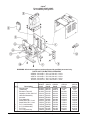
Clarke®
Encore S28XP/S33XP/S38XP
Solution/Recovery System Assembly Drawing 2/04
1
66
29
2
28
5
3
6
7
4
76
32
8
26
9
10
11
12
7
25
24
20
27
13
21
24
23
29
22
18
68
21
45
69
33
46
28
32
76
15
34
31
77
30
78
73 74
75
79
47
49
37
35
16
17
32
36
48
51
50
52
38
39
53
40
81
41
82
24
42
43
44
54
28
55
67
57
56
44
64
60
Page
-36-
62 61 44
44 63
71
72
65
60
58
59
Clarke®
Operator's Manual -Encore S28XP/S33XP/S38XP
70
Clarke®
Encore S28XP/S33XP/S38XP
Solution/Recovery System Assembly Parts List 8/04
Ref #
1
2
3
4
Part No.
34265A
36204A
39338A
40002A
5
6
7
8*
9
10
11
12
13
56459A
87612A
837304
920797
643418
58533A
87026A
85728A
45019A
14
15
16
17
18
19
20
21
22
23
24
25
26
27
77365B
85815A
980652
980205
35192A
77093A
30133A
41809A
82100A
35165A
872010
36903A
30243A
881317
891384
40704A
38020A
962798
980645
81105A
920296
36200A
32409B
32419B
69879A
28
29
30
31
32
33
34
35
Description
Recovery Lid Gasket
Recovery Lid
Stand Tube
Float Switch (include #5
& 2 each #21 & #68)
Strain Relief
Seal
O-Ring
Nut
Gasket
Vac Motor Spacer
Washer, Flat .25
Screw, .25-20 x 4.00 Hex
Vac Motor (also order
2 each #21 and #69)
Label, Battery Installation
Screw, .312-18x1.25 Hex
Washer, Lock .312
Washer, Fender .312
Vac Hose
Label, Falling Parts
Squeegee Adapter
Contact
Locknut
Qty
1
1
1
1
Model
All
All
All
All
1
1
2
1
1
3
3
3
1
All
All
All
All
All
All
All
All
All
1
4
4
4
1
1
1
4
1
Recovery Tank Drain Hose 1
Hose Clamp
3
Hinge Pin
4
Recovery Tank, incl #25 1
Battery - 250 AH - 6 Volt 6
Battery - 330 AH - 6 Volt 6
Battery - 370 AH - 6 Volt 6
Strap
4
Screw, 10-24x.5 Pan
2
Washer, Flat .375
2
Nut, .375-16 ESNA
2
Nut, 10-24 ESNA
4
Solution Lid
1
Front Cover
1
Front Cover
1
Support Bracket
1
All (NI)
All
All
All
All
All (NI)
All
All
All
All
All
All
All
All
All
All
All
All
All
All
All
All
28, 33
38
All
+_
N *Recommended torque
175 5 inch/ pounds.
*kNI
slkklfjsdkfljkflj=sakfljfd
jkNot
lsfdj Illustrated
NOTE: indicates a change has been made
since the last publication of this manual.
Ref #
36
37
38
39
40
41
42
43
44
45
46
47
48
49
50
51
52
53
54
55
56
57
58
59
60
61
62
63
64
65
66
67
68
69
70
71
72
73
74
75
76
77
78
79
80
81
82
Part No.
Description
170892
170915
87622A
80043A
69548A
55723A
85614A
50359A
722030
842406
41206A
41208A
87054A
85703A
30242A
64900A
30454A
962987
833901
833407
839401
832002
962943
30449A
59614A
30445A
50358A
838517
830214
822802
30453A
58069A
98465A
43402A
43401A
839410
980657
962139
39713A
87032A
85524A
962666
962113
51867A
81800A
77092A
61493A**
61494A**
Washer, Lock .25
Screw, .25-20x.75 SS Hex
Washer, Nylon 5/16x5/8x1/32
Screw,Shoulder.25-20x25
Recovery Tank Support
Latch
Screw, 8-32 x .75 Pn.
Barb, ½ NPTF x 3/4 Hose
Hose Clamp
Series Cable - 9"
Series Cable - 16"
Battery Cable
Washer,Fender .375x1¼
Screw, .375-16x 1.50 Hex
Solution Tank
Stationary Handle
Hose
Screw, 10-24x.375 Pn.
Drain Valve Handle
Drain Gasket
Drain Valve
Hose Clamp, Drain Valve
Screw, 8-18x.5 Pn.
Drain Hose
Battery Drain Valve
Solution Hose
Connector
Filter Screen
Hose Adapter
Elbow
Hose
Vac Filter
Clamp, Metal
Housing, Blue
Housing - Black
Asm., Drain Valve
Washer, ¼ Lock
Screw, ¼-20x5/8
Washer, Rubber
Washer
Screw
Screw
Screw 10-32x1
Cable Clamp
Well Nut
Label, Gases & Chem.
Spacer, Latch
Plate, Support
Qty Model
2
2
1
1
1
2
4
1
6
3
2
1
2
2
1
1
2
2
2
2
2
2
2
1
1
2
1
1
1
1
1
1
1
2
2
All
All
All
All
All
All
All
All
All
All
All
All
All
All
All
All
All
All
All
All
All
All
All
All
All
All
All
All
All
All
All
All
All
All
All
1
1
1
1
1
2
1
1
1
1
2
2
All
All
All
All
All
All
All
All
All
All(NI)
All
All
**NOTE: Ref. #'s 81 and 82 were added after Serial # CA2942
Clarke®
Operator's Manual - Encore S28XP/S33XP/S38XP
- 37 -
Clarke®
Encore S28XP/S33XP/S38XP
Brush Motor #45033A 12/03
13
7
12
12
13
2
1
Seam Location
3
14
16
Rotation
4
15
5
6
17
8
9
10
11
Page
-38-
Ref #
Part No. Description
1
2
3
4
5
56478A
40312A
902654
902550
51840A
6
7
8
9
10
11
12
13
14
15
16
17
50520A
56480A
962546
50517A
448396
40826A
55657A
55656A
59805A
50515A
80501A
54238A
Qty
Stator Assembly (w/Magnets & Clips)
Armature Asm.(w/B.E. & F.E. bearings)
Bearings B.E.
Bearing F.E.
Commutator Bracket Assembly
(w/Brush BRD Assembly Leads)
Commutator Bracket
Strain Relief
Brush Board Screw
Brush Board Asm. (w/springs & brushes)
Brush Spring
Brush Assembly
Lead Assembly, Positive
Lead Assembly, Negative
Helical Washer
Thru Bolt
Shaft Key
B.E. Bracket Assembly (Gear Box)
Clarke®
1
1
1
1
1
1
2
2
1
4
4
1
1
1
2
1
1
Operator's Manual -Encore S28XP/S33XP/S38XP
Clarke®
Encore S28XP/S33XP/S38XP
Gear Box #54238A 6/02
9
8
7
6
5
4
3
2
1
Ref #
1
2
3
4
5
6
7
8
9
NI
Clarke®
Part No.
57846A
507641
52050A
56668A
51176A
58316A
902605
54883A
58144A
Description
Ring, Snap
Seal, Oil, Small
Cap End
O'Ring
Bearing, Large
Shaft & Gear, Gearbox
Bearing, Small
Housing
Seal, Oil Large
Darina Grease
Operator's Manual - Encore S28XP/S33XP/S38XP
Qty
1
1
1
1
1
1
1
1
1
4oz.
- 39 -
Clarke®
Encore S28XP/S33XP/S38XP
Vac Motor Assembly #45019A 6/02
13
18
2
1
14
4
3
6
15
5
16
7
8
14
9
15
19
14
10
11
17
12
Ref #
1
2
3
4
5
6
7
8
9
10
Page
Part No.
51913A
54809A
53905A
85303A
40830A
51914A
50618A
53100A
902679
902648
-40-
Description
Clip (optional)
Housing
Fan
Screw - 8-32 x 3/8
Carbon Brushes
Clamp
Bracket
Disc
Bearing - Ball
Bearing - ball, radial
Qty
2
1
1
4
2
2
1
1
1
1
Ref #
11
12
13
14
15
16
17
18
19
Clarke®
Part No.
59803A
50610A
58501A
53914A
658201
53908A
658506
53995A
53996A
Description
Washer - neoprene
Bracket and shell
Spacer
Fan - Rotating
Spacer
Fan - Stationary
Shell
Fan, Air Seal
Fan, Stationary
Qty
1
1
1
3
2
1
1
1
1
Operator's Manual -Encore S28XP/S33XP/S38XP
Clarke®
Part No.
53384A
53385A
80121A
80122A
3
Operator's Manual - Encore S28XP/S33XP/S38XP
2
4 17
5
6
Parking Brake Spare Parts
Description
Pad, Friction
Hub, Shaft
Key, 4 MM - Hub
Set Screw, M3 - Hub
1
7
8
To replace coupler
remove these two
screws (Black)
to seperate the
motor from gearbox
to allow access to
coupler
9
Qty
1
1
1
1
10
Model
RPM
Volt
AMP.
Duty
Date
4
11
4BC-2800
1200
Ins. Cl.
36 VDC Mount
15
Shaft
Cont
Ser. No.
16:1 Ratio
12
1
- 41 -
17
16
1
2
3
4
5
6
7
8
9
10
11
12
13
14
15
Ref #
HP .50
F
Flange
Tang
PERMANENT MAGNET MOTOR
MFG. IN USA
10357A
36508A
53374A
53375A
53376A
53377A
53378A
53379A
53380A
53381A
52663A
69195A
45048A
51720A
30074A
53382A
53383A
54282A
53435A
Clarke
Part #
13
4
2
3
1
Description
Wheel Flange Kit (includes Flange,
Studs, Key, Snap Rings & Shims)
Rubber Mount
Axle Oil Seal
Axle Bearing
Short Axle
Output Gear
Input Plug
Outer Pinion Bearing
Pinion
Inner Pinion Bearing
Steel Ring, Coupler
Rubber Coupler
Motor
Brushes w/Springs (Set of 4)
Motor Brush Cap (internal Threads)
Motor Brush Cap (External Threads)
Long Axle
Gearbox Asm w/o motor
Miter Gear
16
14
15
2
2
2
4
1
1
1
1
1
1
1
1
1
1
4
4
1
1
4
Qty
Clarke®
Encore S28XP/S33XP/S38XP
Imperial Transaxle Parts 12/03
PN 59116A
Transaxle has black motor
Clarke®
Encore S28XP/S33XP/S38XP
36 Volt Battery Charger 6/02
WARNING: All electrical repairs must be performed by qualified personnel only.
PARTS LIST FOR BATTERY CHARGERS
40506A - 36 Volt D.C., 25A, 115 Volt A.C., 60 Hz
40505A - 36 Volt D.C., 25A, 230 Volt A.C., 50 Hz
40507A - 36 Volt D.C., 25A, 230 Volt A.C., 60 Hz
40514A - 36 Volt D.C., 36A, 115 Volt A.C., 60 Hz
40515A - 36 Volt D.C., 36A, 230 Volt A.C., 50Hz
Ref #
1
2
3
4
5
6
7
8
9
10
11
12
Page
-42-
Charger Model Number
40506A 40507A 40505A
Description
Part #
Part #
Part #
Charger Case
42503A 42504A
51959A
Transformer
48400A 48412A
48401A
Electronic Timer Kit
41102A 41103A
41103A
Capacitor, 6 Mfd., 660 V.A.C. 912132 912132
912132
Heat Sink Assembly
912212 912212
912212
Ammeter
40200A 40200A
40200A
Fuse Assembly
912382 912382
912382
Strain Relief, A.C. Cord
837525 837525
837525
Strain Relief, D.C. Cord
747553 747553
747553
D.C. Cord Assembly
51973A 51973A
51973A
A.C. Cord Assembly
51974A 908947
908947
D.C. Plug
911185 911185
911185
D.C. Plug Lock Key
795020 795020
795020
Clarke®
40514A
Part #
41139A
Ref
41102A
912132
43301A
40210A
42704A
747553
737502
42303A
51974A
911185
795020
40515A
Part #
51856A
Ref
41103A
912132
43301A
40210A
42704A
747553
737502
42303A
51857A
911185
795020
Operator's Manual -Encore S28XP/S33XP/S38XP
SEE
PAGES 44 - 59
FOR
COMPONENTS
FOR MACHINES
WITH A
41135C
TRAVERSE
CONTROLLER
Clarke®
Operator's Manual - Encore S28XP/S33XP/S38XP
- 43 -
Clarke®
Encore S28XP/S33XP/S38XP
Control Housing Assembly Drawing 12/03
Drawing# 13713A
(for machines wtih a 41135C Traverse Controller)
1
2
1
3
4
6
5
4
12
9
10
50
43
14
8
7
44
11
45
13
46
47 48
49
15
18
31
19
35
17
42
38
21
32
33
16
17
29 28
30
36
20
26 25 24
23 22 22
34
37
27
40
41
39
Page
-44-
Clarke®
Operator's Manual -Encore S28XP/S33XP/S38XP
Clarke®
Encore S28XP/S33XP/S38XP
Control Housing Assembly Parts List 12/03
(for machines wtih a 41135C Traverse Controller)
Ref #
1
2
3
4
5
6
7
8
9
10
11
12
13
14
15
15A
16
17
18
19
20
21
22
23
24
25
26
27
28
29
30
31
32
33
34
35
36
37
38*
39
40
41
42
43
44
45
46
47
48
49
50
Part No.
55502A
47381B
962262
85612A
53031A
77343B
60058A
44308B
40623A
44416B
38724B
920056
30022A
40085A
40083B
47380A
55413A
170781
980657
854849
83302A
87026A
81104A
41431A
41448A
41422A
41423A
41430A
40179A
60042A
35252B
87052A
912226
85390A
66549A
962139
170892
10052A
60662A
962304
53038A
61266A
66548A
61651A
85391A
87007A
66871A
980651
80043A
77351B
24309B
50883A
Description
Knob
Switch, Head up & down Rocker
Screw, 8-32 x .25 Set
Screw, 10-24 x .375 Pn.
Switch
Control Panel Label
Control Panel
Solution Flow Module
Speed Control Harness
Battery Meter
Spacer
Nut, 6-32 ESNA
Gasket, Panel
Harness, Sequencer
Module Sequencer
Key Switch
Key, Spare
Screw, ¼-20 x 3/4 Set
Lock Washer
Insulator
Stud
Washer
Nut, ¼-20 ESNA
Circuit Breaker 35A
Circuit Breaker 30A Scr.
Circuit Breaker 25A Scr.
Circuit Breaker 5A
Circuit Breaker 1.5A
Main Harness (S Series only)
Stud, 5/16 x 1/4 -20 Thread
Control Housing
Nylon Washer, Key Switch
Hour Meter
Screw, .25-20 x 1.25 Pn
Pin, Left Hand
Screw, .25-20 x .62
Washer, Lock .25
Toggle Switch
Centering Bracket
Screw, Set .312-18 x .5
Control Handle Spring
Control Bracket
Pin, Right Hand
Collar
Screw, .25-20 x .62 Pn
Washer
Retainer Key/Hour Meter
Washer, Nylon IDxODx.034
Screw, Shoulder
Label, Control Wiring
Control Handle
Retainer, Potentiometer
Qty
2
1
2
6
1
1
1
1
1
1
2
2
1
1
1
1
1
1
3
1
1
2
1
2
1
1
1
1
1
1
1
1
1
2
1
2
2
1
1
4
2
1
1
1
2
2
1
1
1
1
1
1
*#38 must use red loctite set screws.
Clarke®
Operator's Manual - Encore S28XP/S33XP/S38XP
- 45 -
Clarke®
Encore S28XP/S33XP/S38XP
Rear Cover Assembly Drawing 6/02
(for machines wtih a 41135C Traverse Controller)
1
2
3
4
5
2 18
17
6
16
15
4
7
10
20
14
21 5 17
13
23
26
8
11
12
22
9
15
25
28
24
30
24
17
22
43
44
33
39
40
23
35
30
48
47
45
31
42 29
41
45
46
32
38
22 34
36
37
17
49
27
46
Page
-46-
Clarke®
Operator's Manual -Encore S28XP/S33XP/S38XP
Clarke®
Encore S28XP/S33XP/S38XP
Rear Cover Assembly Parts List 6/02
(for machines wtih a 41135C Traverse Controller)
Ref #
Part No. Description
Qty
1
2
3
4
5
6
7
8
9
10
11
12
13
14
15
16*
17
18
19
20
21
22
23
24
25
26
27
85700A
87026A
608210
902731
920056
67476A
65629A
438360
960510
61265A
68643A
980675
962546
47388A
962980
962304
81104A
65628A
61682A
41208A
41140A
87007A
980657
83307A
962139
69878A
77079A
77080A
41801A
77194B
193951
54763A
54764A
69372A
98465A
85806A
40125A
980651
80043A
41135C
962992
42405A
77355A
32418B
85391A
60233A
962957
77221A
83010A
930093
1
2
1
2
4
1
1
1
1
1
1
2
2
1
4
2
9
1
1
Ref
1
6
4
8
5
1
1
1
2
1
1
4
2
1
1
1
1
2
2
1
4
1
1
1
2
2
4
1
1
2
28
29
30
31
32
33
34
35
36
37
38
39
40
41
42
43
44
45
46
48
47
49
Screw, .25-20x1.00 Hex
Washer, Flat .25
Spacer
Nylon Bearing
Nut, 6-32 ESNA
Shaft
Squeegee Lever
Spring
Shoulder Screw
Squeegee Lift Bracket
Wear Plate
Washer
Screw, 10-24 x .50 Pn
Switch
Screw, 6-32 x 1.00 Pn
Screw, .312-18 x .50 Set
Nut, .25-20 ESNA
Lever Weld.
Upper Cable Assembly
Battery Cable
Cable Assembly
Washer
Washer, Lock
Stud, ¼-20
Screw, .25-20x.62 Hex
Plug Bracket
Label, w/Brake Warning
Label, w/o Brake Warning
Solenoid - Main / Brush
Label, Traverse
Trim, 4½" & 8"
Insert
Insert
Lower Electrical Panel
Clamp, Metal 7/18
Screw, ¼-20 x 3/4 Hex
Solenoid - Vac
Washer
Shoulder Screw
Traverse, Control Board
Screw, 8-32 x.74 Pn
Diode
Label
Rear Cover
Screw, .25-20 x.62 Pn
Hose Bracket
Screw, 10-16 x ½
Serial Tag
Rivet, Pop
Rivet
*#16 must use red loctite.
Clarke®
Operator's Manual - Encore S28XP/S33XP/S38XP
- 47 -
Clarke®
Encore S28XP/S33XP/S38XP
Electrical Schematic 6/02
(for machines wtih a 41135C Traverse Controller)
Page
-48-
Clarke®
Operator's Manual -Encore S28XP/S33XP/S38XP
Clarke®
Encore S28XP/S33XP/S38XP
Connection Diagram 6/02
(for machines wtih a 41135C Traverse Controller)
Clarke®
Operator's Manual - Encore S28XP/S33XP/S38XP
- 49 -
NOTES
Page
-50-
Clarke®
Operator's Manual -Encore S28XP/S33XP/S38XP
SEE
PAGES 52 - 57
FOR
COMPONENTS
FOR MACHINES
WITH A
40089A
TRAVERSE
CONTROLLER
Clarke®
Operator's Manual - Encore S28XP/S33XP/S38XP
- 51 -
Clarke®
Encore S28XP/S33XP/S38XP
Control Housing Assembly Drawing 12/03
Drawing# 13713A
(for machines wtih a 40089A Traverse Controller)
1
2
1
3
4
6
5
4
12
9
10
11
49
8
7
44
43
45
13
46 47 48
14
15
18
31
19
35
17
42
38
21
32
33
16
17
29 28
30
36
20
26 25 24 23
22 22
34
37
27
40
41
39
Page
-52-
Clarke®
Operator's Manual -Encore S28XP/S33XP/S38XP
Clarke®
Encore S28XP/S33XP/S38XP
Control Housing Assembly Parts List 12/03
(for machines wtih a 40089A Traverse Controller)
Ref #
1
2
3
4
5
6
7
8
9
10
11
12
13
14
15
15A
16
17
18
19
20
21
22
23
24
25
26
27
28
29
30
31
32
33
34
35
36
37
38*
39
40
41
42
43
44
45
46
47
48
49
NI
Part No.
55502A
47381B
962262
85612A
53031A
77343B
60058A
44308B
40623A
44416B
38724B
920056
30022A
40623A
24309B
47380A
55413A
170781
980657
854849
83302A
87026A
81104A
41431A
41448A
41422A
41423A
41430A
40179B
60042A
35252B
87052A
912226
85390A
66549A
962139
170892
10052A
60662A
962304
53038A
61266A
66548A
61651A
85391A
87007A
66871A
980651
80043A
77351C
50883A
42909A
Description
Knob
Switch, Head up & down Rocker
Screw, 8-32 x .25 Set
Screw, 10-24 x .375 Pn.
Switch
Control Panel Label
Control Panel
Solution Flow Module
Speed Control Harness
Battery Meter
Spacer
Nut, 6-32 ESNA
Gasket, Panel
Harness, Traverse
Control Handle
Key Switch
Key, Spare
Screw, ¼-20 x 3/4 Set
Lock Washer
Insulator
Stud
Washer
Nut, ¼-20 ESNA
Circuit Breaker 35A
Circuit Breaker 30A Scr.
Circuit Breaker 25A Scr.
Circuit Breaker 5A
Circuit Breaker 1.5A
Main Harness
Stud, 5/16 x 1/4 -20 Thread
Control Housing
Nylon Washer, Key Switch
Hour Meter
Screw, .25-20 x 1.25 Pn
Pin, Left Hand
Screw, .25-20 x .62
Washer, Lock .25
Toggle Switch
Centering Bracket
Screw, Set .312-18 x .5
Control Handle Spring
Control Bracket
Pin, Right Hand
Collar
Screw, .25-20 x .62 Pn
Washer
Retainer Key/Hour Meter
Washer, Nylon IDxODx.034
Screw, Shoulder
Label, Control Wiring
Retainer, Potentiometer
Fuse, 5 Amp ACG (included w/item#27)
Qty
2
1
2
6
1
1
1
1
1
1
2
2
1
1
1
1
1
1
3
1
1
2
1
2
1
1
1
1
1
1
1
1
1
2
1
2
2
1
1
4
2
1
1
1
2
2
1
1
1
1
1
2
*#38 must use red loctite set screws.
Clarke®
Operator's Manual - Encore S28XP/S33XP/S38XP
- 53 -
Clarke®
Encore S28XP/S33XP/S38XP
Rear Cover Assembly Drawing 10/02
(for machines wtih a 40089A Traverse Controller)
1
2
3
4
5
2 18
17
6
16
15
4
7
10
14
17
13
20
21 5
23
26
8
11
12
22
9
15
53
25
24
28
30
24
52
51
50
43 17
22
44
32
31
29
42
41
45
33
39
40
47
46
45
23
35
30
48
38
22 34
36
37
17
49
27
46
Page
-54-
Clarke®
Operator's Manual -Encore S28XP/S33XP/S38XP
Clarke®
Encore S28XP/S33XP/S38XP
Rear Cover Assembly Parts List 10/02
(for machines wtih a 40089A Traverse Controller)
Ref #
Part No. Description
Qty
1
2
3
4
5
6
7
8
9
10
11
12
13
14
15
16*
17
18
19
20
21
22
23
24
25
26
27
85700A
87026A
608210
902731
920056
67476A
65629A
438360
960510
61265A
68643A
980675
962546
47388A
962980
962304
81104A
65628A
61682A
41208A
41140A
87007A
980657
83307A
962139
69878A
77079A
77080A
41802A
77194B
193951
54763A
54764A
69372A
98465A
85806A
40125A
980651
80043A
41135C
962992
42405A
77355A
32418B
85391A
60223A
962957
77221A
83010A
930093
41801A
60552A
920722
912287
1
2
1
2
4
1
1
1
1
1
1
2
2
1
4
2
9
1
1
Ref
1
6
4
8
5
1
1
1
1
1
1
4
2
1
1
1
1
2
2
1
4
1
1
1
2
2
4
1
1
2
1
1
1
1
28
29
30
31
32
33
34
35
36
37
38
39
40
41
42
43
44
45
46
48
47
49
50
51
52
53
Screw, .25-20x1.00 Hex
Washer, Flat .25
Spacer
Nylon Bearing
Nut, 6-32 ESNA
Shaft
Squeegee Lever
Spring
Shoulder Screw
Squeegee Lift Bracket
Wear Plate
Washer
Screw, 10-24 x .50 Pn
Switch
Screw, 6-32 x 1.00 Pn
Screw, .312-18 x .50 Set
Nut, .25-20 ESNA
Lever Weld.
Upper Cable Assembly
Battery Cable
Cable Assembly
Washer
Washer, Lock
Stud, ¼-20
Screw, .25-20x.62 Hex
Plug Bracket
Label, w/Brake Warning
Label, w/o Brake Warning
Solenoid - Main
Label, Traverse
Trim, 4½" & 8"
Insert
Insert
Lower Electrical Panel
Clamp, Metal 7/18
Screw, ¼-20 x 3/4 Hex
Solenoid - Vac
Washer
Shoulder Screw
Traverse, Control Board
Screw, 8-32 x.74 Pn
Diode
Label
Rear Cover
Screw, .25-20 x.62 Pn
Hose Bracket
Screw, 10-16 x ½
Serial Tag
Rivet, Pop
Rivet
Solenoid, Brush
Bracket
Nut, 10-32 ESNA
Rectifier
*#16 must use red loctite.
Clarke®
Operator's Manual - Encore S28XP/S33XP/S38XP
- 55 -
Clarke®
Encore S28XP/S33XP/S38XP
Electrical Schematic 10/02
(for machines wtih a 40089A Traverse Controller)
Page
-56-
Clarke®
Operator's Manual -Encore S28XP/S33XP/S38XP
Clarke®
Encore S28XP/S33XP/S38XP
Connection Diagram 10/02
(for machines wtih a 40089A Traverse Controller)
Clarke®
Operator's Manual - Encore S28XP/S33XP/S38XP
- 57 -
NOTES
PRODUCT SUPPORT BRANCHES
U. S. A. Locations
CORPORATE OFFICE
ALTO U.S. Inc., St. Louis, Missouri
16253 Swingley Ridge Road, Suite 200
Chesterfield, Missouri 63017-1725
PRODUCTION FACILITIES
Clarke®, Springdale, Arkansas
2100 Highway 265
Springdale, Arkansas 72764
(479) 750-1000
Customer Service - 1-800-253-0367
Technical Service - 1-800-356-7274
®
American Lincoln , Bowling Green, Ohio 43402
1100 Haskins Road
SERVICE FACILITIES
Clarke®, Elk Grove, Illinois 60007
2280 Elmhurst Road
(847) 956-7900
Clarke®, Denver, Colorado 80204
1955 West 13th Ave.
(303) 623-4367
Clarke®, Houston, Texas 77040
7215 North Gessner Road
713-937-7717
SERVICE AND SALES FACILITY
American Lincoln® / Clarke®, Madison Heights,
Michigan 48071-0158
29815 John R.
(810) 544-6300
American Lincoln® / Clarke®, Marietta, Georgia 30066
1455 Canton Road
(770) 973-5225
SALES AND DISTRIBUTION CENTER
Clarke®, Secaucus, NJ 07094
74 Henry Street
(201) 864-5503
Clarke®
Clarke American Sanders
A.L. Cook
Customer Service Headquarters and Factory
2100 Highway 265
Springdale, Arkansas 72764
(479) 750-1000
Technical Service
1-800-356-7274
European Locations
PRODUCTION FACILITIES
ALTO Danmark A/S, Aalborg
Blytaekkervej 2
DK-9000 Aalborg
+45 72 18 21 00
ALTO Danmark A/S, Hadsund
Industrikvarteret
DK-9560 Hadsund
+45 72 18 21 00
SALES SUBSIDIARIES
Clarke® Canada Ltd., Rexdale Ontario
24 Constellation Ct.
(416) 675-5830
ALTO Overseas Inc., Sydney (Australia)
1B/8 Resolution Drive
Caringbah NSW 2229
+61 2 9524 6122
ALTO Cleaning Systems Asia Pte Ltd., Singapore
No. 17 Link Road
Singapore 619034
+65 268 1006
ALTO Deutschland GmbH, Bellenberg (Germany)
Guido-Oberdorfer-Straße 2-8
89287 Bellenberg
+49 0180 5 37 37 37
ALTO Cleaning Systems (UK) Ltd., Penrith
Gilwilly Industrial Estate
Penrith
Cumbria CA11 9BN
+44 1768 868 995
ALTO France S.A. Strasbourg
B.P. 44, 4 Place d’Ostwald
F-67036 Strasbourg
Cedex 2
+33 3 8828 8400
ALTO Nederland B.V.
Postbus 65
3370 AB Hardinxveld-Giessendam
The Netherlands
+31 184 677 200
ALTO Sverige AB, Molndal (Sweden)
Aminogatan 18
Box 4029
S-431 04 Molndal
+46 31 706 73 00
ALTO Norge A/S, Oslo (Norway)
Bjornerudveien 24
N-1266
+47 2275 1770
Clarke® LIMITED U.S. WARRANTY
This Clarke Industrial/Commercial Product is warranted to be free from defects in materials and workmanship under
normal use and service, when operated and maintained in accordance with Clarke's Maintenance and Operations instructions. The warranty period is subject to the conditions stated below.
3 YEARS FOR PARTS AND 1 YEAR FOR SERVICE LABOR (See exceptions below)
Motors must be inspected for carbon motor brush wear at six-month intervals by an authorized Clarke repair station.
Failure to comply with the six-month inspection requirement or failure to replace worn motor brushes identified during the
inspection will void the warranty on the motors. Cost of the six-month inspection and replacement of carbon motor brushes
is the responsibility of the purchaser. In the event of a warranty claim on the motors, proof of inspection and any required
motor brush replacement must be provided. This warranty is extended only to the original purchaser for use of the product.
It does not cover normal wear parts such as electrical cable, rubber parts, hoses and motor brushes.
BATTERY WARRANTY
In addition to the items above, any original equipment Clarke Battery which becomes unserviceable under normal use within
a period of ninety (90) days from date of sale to the original user will be repaired or replaced with one of equal specification
at our option, F.O.B. any authorized Clarke Sales or Service Branch, with no charge to the user, except transportation
costs. After expiration of the above ninety (90) day period, any battery which fails under normal use will be adjusted to the
original user with a new battery of equal specification on an eighteen (18) months pro rate basis from the date of purchase.
Adjustment will be determined using the then current list price, plus transportation costs.
Warranty is rendered null and void if battery is not kept filled to the proper level with DISTILLED WATER.
CLARKE: POLYDUR® AUTOMATIC SCRUBBER SOLUTION AND RECOVERY TANK EIGHT-YEAR U.S.
GUARANTEE
Your new Clarke Encore XP has polydur Solution and Recovery Tanks. Polydur is a rotationally molded, low-density
linear polyethylene that won't crack or dent, and withstands most corrosives and temperature extremes. Clarke backs
up your Polydur tanks with an eight-year guarantee. If a tank breaks or leaks under normal use within eight years of
the date of purchase, it will be replaced free.
CLARKE UNIBODY FRAME EIGHT-YEAR U.S. WARRANTY
Clarke warranties the frame of the Encore XP for a period of eight years against defects in materials and workmanship
under normal use and service.
STATED WARRANTIES ARE IN LIEU OF ALL OTHER WARRANTIES, EXPRESSED OR IMPLIED
Clarke's liability under this warranty is limited to repair of the product and/or replacement of parts and is given to purchaser
in lieu of all other remedies, including INCIDENTAL AND CONSEQUENTIAL DAMAGES.
THERE ARE NO EXPRESS WARRANTIES OTHER THAN THOSE SPECIFIED HEREIN. THERE ARE NO WARRANTIES WHICH
EXTEND BEYOND THE DESCRIPTION OF THE FACE HEREOF. NO WARRANTIES, INCLUDING BUT NOT LIMITED TO WARRANTY OF MERCHANTABILITY, SHALL BE IMPLIED. A warranty registration card is provided with your Clarke product.
Return the card to assist Clarke in providing the performance you expect from your new floor machine.
If a difficulty develops with the product, you should: a) Contact the nearest authorized Clarke repair location or contact the
Clarke Service Operations Department, 2100 Highway 265, Springdale, Arkansas 72764, for the nearest authorized Clarke
repair location. Only these locations are authorized to make repairs to the product under this warranty. (b) Return the
product to the nearest Clarke repair location. Transportation charges to and from the repair location must be prepaid by the
purchaser. Clarke will repair the product and/or replace any defective parts with out charge within a reasonable time after
receipt of the product.
Clarke, 2100 Highway 265, Springdale, Arkansas 72764.
Clarke reserves the right to make changes or improvements to its machine without notice.
Always use genuine Clarke Parts for repair.
2100 Highway 265
Springdale, Arkansas, 72764