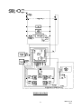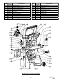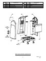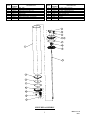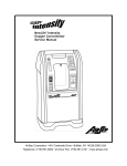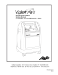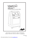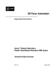
1
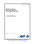
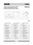
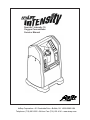
NewLife® Intensity 10 Oxygen Concentrator Service Manual AirSep Corporation • 401 Creekside Drive • Buffalo, NY 14228-2085 USA Telephone: (716) 691-0202 • 24-Hour Fax: (716) 691-4141 • www.airsep.com Expedited Product Warranty Check service is always at your fingertips with AirSep: Type: http://www.airsep.com/medical/equipmentproviders.html OR In the US or Canada, dial 866-873-9277 AirSep® is a registered trademark of AirSep Corporation. NewLife® is a trademark of AirSep Corporation. ii MN134-1 rev A 08/11 Table of Contents Section 1.0 Introduction 1.1 Equipment Provider Responsibility 1 1.2 Important Notice and Symbol Explanations 2 1.3 NewLife® Intensity 10 Product Warranty 4 1.4 Functional Specifications 5 2.1 Description of Operation 6 2.2 Operation Check 6 2.3 Alarm System 6 2.3.1 Start Up/Battery Test 2.3.2 Power Failure Alarm Test 7 7 2.4 Oxygen Concentration Test and Specification 7 3.1 Instructions 8 3.2 Routine Maintenance by the Patient 8 3.2.1 Cleaning the Air Intake Gross Particle Filter 3.2.2 Checking the Alarm System Battery 8 8 Instructions 9 4.1.1 Air Intake Gross Particle Filter/GPF 4.1.2 Felt Filter Replacement 4.1.3 Product Filter 4.1.4 Battery Replacement 4.1.5 Recording Maintenance 9 9 9 9 10 Preparing for New Patient Use/Method of Cleaning and Infection Control 10 Section 2.0 Operation Check and Oxygen Concentration Test Section 3.0 Patient Instructions Section 4.0 Provider Instructions 4.1 4.2 iii MN134-1 rev A 08/11 Section 5.0 Main Components 5.1 Components 11 5.2 Cabinet Removal 11 5.2.1 5.2.2 5.2.3 5.2.4 5.2.5 5.2.6 11 11 11 11 11 11 5.3 5.4 5.5 5.6 5.7 Removing Side Panel(s) Removing Back Panel Removing Lower Front Panel Removing Control Panel Superstructure Caster Replacement Compressor 12 5.3.1 5.3.2 12 13 Compressor Replacement Capacitor Replacement Solenoid Valves 13 5.4.1 Feed/Waste Valve Replacement 5.4.2 Solenoid Valve Coil Replacement 13 13 Sieve Beds 14 5.5.1 14 Sieve Bed Replacement Cabinet Fan 15 5.6.1 15 Cabinet Fan Replacement Circuit Board 15 5.7.1 16 Circuit Board Replacement 5.8 Product Tank Replacement 16 5.9 Product Regulator Check and Setting 17 5.9.1 Setting Product Regulator for Normal Operation 5.9.2 Product Regulator Cleaning or Rebuilding 17 18 5.10 Circuit Breaker Replacement 18 5.11 I/0 Power Switch Replacement 18 5.12 Buzzer Replacement 19 5.13 Hour Meter Replacement 19 5.14 Flowmeter Replacement 19 5.15 Power Cord Replacement 19 5.16 Oxygen Monitor Circuit Board Replacement 20 iv MN134-1 rev A 08/11 Section 6.0 Troubleshooting 6.1 Operating Pressure Test 21 6.1.1 High Operating Pressure 6.1.2 Low Operating Pressure 21 21 6.2 General Troubleshooting 22 6.3 Troubleshooting Chart 23 6.4 Tool Kit and Pressure Test Gauge 26 Appendix Exploded Drawings Wiring Diagram – Intensity 10 120V A Wiring Diagram – Intensity 10 220/240V B Control Panel Assembly C Main Structure Assembly D Base and Cabinet Components E Product Tank/Regulator Assembly F Valve Block Assembly G Compressor Assembly H Sieve Bed Assembly I v MN134-1 rev A 08/11 1.0 Introduction 1.1 Equipment Provider Responsibility All Equipment Providers of the NewLife® Intensity 10 Oxygen Concentrator must assume responsibilities for handling, operational check-out, patient instruction, and oxygen concentration checks. These responsibilities are outlined below and throughout this manual. As an Equipment Provider, you must do all of the following: Inspect the condition of each NewLife Intensity 10 unit immediately upon delivery to your business location. Note any sign of damage on the delivery receipt, and report it directly to both the freight company and AirSep Corporation immediately. Check the operation of each NewLife Intensity 10 before delivery to a patient. Confirm the oxygen concentration level is within specifications, as referred to in Section 2.4. (Test the battery and power disconnect alarm, as described in Section 2.3 of this manual.) Deliver NewLife Intensity 10 units only to patients authorized by a licensed health care provider or physician’s prescription. The NewLife Intensity 10 must not be used as a life-supporting device. A backup supply of oxygen must be available. Instruct patients how to use the NewLife Intensity 10 in conjunction with the Patient Manual. Instruct patients to notify their licensed health care provider/physician if they experience any signs of discomfort. Instruct each patient how to perform routine maintenance of the air intake gross particle filter and how to check the alarm system battery. (Refer to Section 3.2.) Be available to provide service to each patient at any time. Maintain the NewLife Intensity 10 in accordance with Section 4.0. Establish and implement a protocol to check oxygen concentration. Repair components and replace parts only as outlined in this manual. Use only AirSep parts for replacement in NewLife Intensity 10 Oxygen Concentrators. Refer to the NewLife Intensity 10 Product Warranty if parts replacement is required within the warranty period. This unit is not a life-support device. Geriatric, pediatric, or any other patient unable to communicate discomfort while using this oxygen concentrator may require additional monitoring. Patients with hearing and/or sight impairments may need assistance with monitoring the alarms. This device supplies high-concentration oxygen that promotes rapid burning. Do not allow smoking or open flames within the same room of (1) this device, or (2) any oxygen-carrying accessory. Failure to observe this warning can result in severe fire, property damage, and/or cause physical injury or death. Use no oil, grease, or petroleum-based or other flammable products on or near nasal end of cannula or on the Intensity 10 unit. Oxygen accelerates the combustion of flammable substances. 1/ 1 MN134-1 rev A 08/11 1.2 Important Notice and Symbol Explanations As you read the manual, pay special attention to the WARNING, CAUTION, and NOTE messages. They identify safety guidelines or other important information as follows: Describes a hazard or unsafe practice that can result in severe bodily injury or death. Describes a hazard or unsafe practice that can result in minor bodily injury or property damage. Provides information important enough to emphasize or repeat. Symbols are frequently used on equipment in preference to words with the intention of lessening any possibility of misunderstanding caused by language differences. Symbols can also permit easier comprehension of a concept within a restricted space. The following table is a list of symbols and definitions that may be used with the NewLife Intensity 10 Oxygen Concentrator. These symbols are referenced from the appropriate International Electrotechnical Commission (IEC) standards: Symbol Description Symbol Description On (power switched on) Do not disassemble Off (power switched off) Consult instructions for use Type B device Keep in vertical position Class II device Fragile – handle with care Do not smoke Oxygen concentration warning LED Complies with the 93/42/EEC directive drawn up by the approved organization n˚ 0459 Caution: US federal law restricts this device for sale or rental by or on order of a licensed healthcare provider Do not expose to open flames Gas outlet, connection to the circuit Do not grease WEEE Directive Consult the accompanying documents Keep unit and accessories dry 2 MN134-1 rev A 08/11 Method for disposing of waste: All waste from the NewLife Intensity 10 (patient circuit, etc.) must be disposed of using appropriate methods. Method for disposing of the device: In order to preserve the environment, the concentrator must only be disposed of using the appropriate methods. Conformity with EN 60-601 (§ 6.8.2 b): “The manufacturer, assembler, installer or importer are not considered to be responsible themselves for the consequences on the safety, reliability and characteristics of a device unless: - The assembly, fitting, extensions, adjustments, modifications, or repairs have been performed by persons authorized by the party in question. - The electrical installation of the corresponding premises complies with IEC regulations. - The device is used in accordance with the instructions for use.” If the replacement parts used for the periodic servicing by an approved technician do not comply with the manufacturer’s specifications, the latter is absolved from all responsibility in the event of an accident. Do not open the device while in operation: risk of electrical shock. This device complies with the requirements of the 93/42/EEC European directive but its operation may be affected by other devices being used close by, such as diathermy and high frequency electro-surgical equipment, defibrillators, short wave therapy equipment, mobile telephones, CB and other portable devices, microwave ovens, induction plates or even remote control toys, and more generally electromagnetic interferences, which exceed the levels specified by the EN 60601-1-2 standard. Classification Type of protection against electric shock: Class II Protection from electric shock is achieved by DOUBLE INSULATION. Protective earthing or reliance upon installation conditions are not required. Degree of protection against electric shock: Type B Equipment providing a particular degree of protection against electric shock, particularly regarding: 1) allowable leakage current; 2) reliability of protective earth connection (if present). Not intended for direct cardiac application. Degree of protection against harmful ingress of water: Drip-proof equipment – IPX1. Equipment provided with an enclosure preventing entry of such an amount of falling liquid as might interfere with the satisfactory and safe operation of the equipment. Method of cleaning and infection control allowed: Please refer to the Maintenance section in the NewLife Intensity 10 Service Manual. Degree of safety of application in the presence of flammable anesthetic gases: Equipment not suitable for such application. Mode of operation: Continuous duty. 3 MN134-1 rev A 08/11 1.3 NewLife Intensity 10 Product Warranty AirSep Corporation warrants the NewLife Intensity 10 Oxygen Concentrator to be free from defect in parts and workmanship for one, three, or five years (as specified on the original invoice provided) from the date of delivery to the original purchaser, under normal use and operation. AirSep Corporation’s obligations under this warranty are limited to the repair or replacement of any such item of equipment (or part thereof) shown to be defective or, at AirSep Corporation’s option, to refunding the purchase price of any such defective item of equipment. Each item of equipment for which a warranty claim is asserted shall, at the request of AirSep Corporation, be returned on a prepaid basis with proof of purchase date to the AirSep factory at the expense of the purchaser. The purchaser will be responsible for freight charges. Replacement parts shall be warranted as stated above for the unexpired portion of the original one-, three-, or five-year parts warranty. This warranty does not extend to any item or part subjected to misuse, accident, improper application, or which has been repaired or altered outside of the AirSep Corporation Factory without the express prior written authorization of AirSep Corporation. THE FOREGOING WARRANTY IS IN LIEU OF ANY OTHER WARRANTY, EXPRESSED OR IMPLIED, IN FACT OR IN LAW, INCLUDING WITHOUT LIMITATION THE WARRANTY OF MERCHANTABILITY OR THE WARRANTY OF FITNESS FOR PARTICULAR PURPOSE. IT IS EXPRESSLY UNDERSTOOD THAT PURCHASER’S SOLE AND EXCLUSIVE REMEDY FOR DEFECT IN PARTS IS LIMITED TO ENFORCEMENT OF AIRSEP CORPORATION’S OBLIGATION AS SET FORTH ABOVE, AND AIRSEP CORPORATION SHALL NOT BE LIABLE TO PURCHASER OR OTHERS FOR LOSS OF USE OF THE EQUIPMENT OR FOR OTHER SPECIAL, INCIDENTAL, OR CONSEQUENTIAL DAMAGES. 4 MN134-1 rev A 08/11 1.4 Functional Specifications Oxygen Concentration: 2-9 LPM: 92% +3.5/-3% 10 LPM: 90% +5.5/-3% (Based on 70°F [21°C] at sea level) Accuracy: Flowmeter ± 10% or ± 200ml of indicated flow, whichever is greater. Response Time: Allow 5 minutes to attain maximum oxygen concentration. Positioning: Operate the unit in an upright position, maintaining at least 12 inches (30.5cm) of open space on all sides for ventilation. Dimensions: 27.5 in. high x 16.5 in. wide x 14.5 in. deep (69.9 cm high x 41.9 cm wide x 36.8 cm deep) Weight: 58 lb; shipping weight – 65 lb (26.3 kg; shipping weight – 29.5 kg) Electrical: 120 VAC, 60 Hz, 6.0 amps, 590 watts 220-240 VAC, 50 Hz, 3.0 amps, 590 watts Two-prong polarized plug Double-insulated cabinet Alarms: Power Failure Low Oxygen Concentration (with optional Oxygen Monitor) Low Pressure High Pressure High Temperature Battery Test Operating Temperature Range: 41°F to 104°F (5°C to 40°C) for 120 VAC 60 Hz models 41°F to 95°F (5°C to 35°C) for 220-240 VAC 50 Hz models Storage Temperature Range: -4°F to 140°F (-20°C to 60°C) Humidity: Up to 95% (non-condensing) 5 MN134-1 rev A 08/11 2.0 Operational Check and Oxygen Concentration Test 2.1 Description of Operation Air is drawn into the NewLife Intensity 10 Oxygen Concentrator through an external air intake gross particulate filter. Before this air enters the compressor, it passes through the unit’s suction resonator which, quiets the compressor’s suction sound. Pressurized air then exits the compressor and passes through a heat exchanger. The heat exchanger reduces the temperature of the compressed air. Next, a two-way solenoid feed valve directs the air into one of two sieve beds that contain molecular sieve. The unique property of molecular sieve enables it to physically attract (adsorb) nitrogen when air passes through this material, thus producing high concentrated oxygen. There are two sieve beds: while one produces high concentration oxygen, the other is purged of the nitrogen it adsorbed (collected) during this pressure swing adsorption (PSA) cycle. Each adsorber produces oxygen and delivers it to the product tank. Oxygen exits the product tank through a pressure regulator, flow control valve, and flowmeter. The NewLife Intensity 10 unit delivers up to 95.5% oxygen at flow rates from 2-10 lpm. 2.2 Operation Check AirSep tests every NewLife Intensity 10 Oxygen Concentrator thoroughly after manufacture. You must perform the following test to ensure that no damage occurred in shipping or handling. Do not use extension cords with this unit or connect too many plugs into the same electrical outlet. The use of extension cords could adversely affect the performance of the device. Too many plugs into one outlet can result in an overload to the electrical panel, causing the breaker/fuse to activate or fire if the breaker or fuse fails to operate. 2.3 1. Open and inspect all cartons (that contain units) upon delivery. Unpack the unit and remove it from the carton. Inspect the unit itself for damage. If the exterior of a unit’s carton is damaged, or the unit itself is damaged, note it on the freight bill signed by the driver. 2. Connect unit to power, and set the I/0 power switch to the “I” position. Check to see that the following occurs: a. A continuous alarm sounds for approximately five seconds. See the troubleshooting chart in Section 6.3 of this manual if the unit’s alarm does anything other than sound for five seconds. b. The compressor runs and flow is indicated in flowmeter. c. OPTIONAL: The Oxygen Monitor’s amber light remains on until the oxygen concentration reaches 85% ±3% (approximately two minutes). Perform an oxygen concentration test, as described in Section 2.4. Alarm System The NewLife Intensity 10 Oxygen Concentrator is equipped with a battery-powered alarm system, which sounds a continuous and loud alarm when a power failure occurs. It sounds MN134-1 rev A 6 08/11 an intermittent alarm if the high or low pressure indicators are activated or if the optional oxygen monitor detects lower than therapeutic levels of oxygen concentration. The alarm remains on until you correct the alarm condition or you set the I/0 power switch to the “0” position. Refer to Section 6.0 for a list of probable alarm causes. 2.3.1 Start Up/Battery Test Each time the NewLife Intensity 10 unit is turned on, an alarm should sound for approximately five seconds. The audio alarm must sound for approximately five seconds each time the unit is turned to the “I” position to indicate the battery is in good condition. 2.3.2 Power Failure Alarm Test To test the power failure alarm, disconnect the unit from power, set the l/0 power switch to the “I” position. This should activate the audio alarm. If it does not, refer to the troubleshooting chart in Section 6.3 of this manual. 2.4 Oxygen Concentration Test and Specification To ensure that the unit’s output of oxygen is within specification, you must perform a test of the oxygen concentration. Test the unit upon delivery to a patient and at periodic intervals. Equipment Providers need to establish and implement a protocol to check oxygen concentration. 1. If a humidifier bottle is used, disconnect it. 2. Connect a calibrated oxygen concentration analyzer to the oxygen outlet. 3. Verify that the product flow rate delivered by the unit matches the patient’s prescription and does not exceed the capacity of the unit. 4. Set the unit’s l/0 power switch to the “I” position. Allow approximately five minutes for the oxygen concentration to stabilize. Take oxygen concentration readings and verify levels are within specification at the liter flow being tested. 5. Disconnect the oxygen analyzer, and reconnect the humidifier bottle (if used). Do not measure oxygen concentration output after the product stream passes through a humidifier bottle, or erroneous readings will result. AirSep NewLife Intensity 10 Concentration Specifications Liter Flow Oxygen Concentration 2-9 lpm 10 lpm 92% +3.5/-3% 90% +5.5/-3% 7 In Spec 89% or higher 87% or higher MN134-1 rev A 08/11 3.0 Patient Instructions 3.1 Instructions It is important that patients thoroughly understand how to operate the AirSep NewLife Intensity 10 unit. This enables proper treatment, as prescribed by a licensed health care provider/physician. If patients experience any discomfort or the unit alarms, they must notify their licensed health care provider/physician immediately. You, as the Equipment Provider, are responsible to see that each patient receives the Patient Manual. Explain each step in the operation of the unit to the patient in reference to this manual. This device supplies high-concentration oxygen that promotes rapid burning. Do not allow smoking or open flames within the same room of (1) this device, or (2) any oxygen-carrying accessory. Failure to observe this warning can result in severe fire, property damage, and /or cause physical injury or death. 3.2 Routine Maintenance by the Patient To ensure accurate output and efficient operation of the unit, the patient must perform two simple routine maintenance tasks: Clean the air intake gross particle filter Check the alarm system battery 3.2.1 Cleaning the Air Intake Gross Particle Filter The patient must clean this filter weekly, as described below. The filter may require daily cleaning if the NewLife Intensity 10 unit operates in a harsh environment such as a house heated by wood, kerosene, or oil, or one with excessive cigarette smoke. 1. Remove the dirty air intake gross particle filter from the back of the NewLife Intensity 10 unit, and install a clean filter, as described above. 2. Wash the dirty filter in warm soapy water, and rinse. 3. Use a soft absorbent towel to remove excess water. 4. Keep the clean, dry filter readily available for next use. 3.2.2 Checking the Alarm System Battery The alarm system battery is tested each time the l/0 power switch is set to the “l” position. A continuous alarm sounds for approximately five seconds to indicate a good battery. If the alarm does anything other than sound for five seconds, instruct the patient to call the Equipment Provider immediately. 8 MN134-1 rev A 08/11 4.0 Provider Instructions 4.1 Instructions To ensure that the unit’s output of oxygen is within specification, you must perform a test of the oxygen concentration. Test the unit upon delivery to a patient and at periodic intervals. Equipment Providers need to establish and implement a protocol to check oxygen concentration. (Refer to Section 2.4.) AirSep does not require preventative maintenance on the concentrator. You do not need to perform any maintenance as long as the NewLife Intensity 10 unit remains within specifications at the desired flow rate. 4.1.1 Air Intake Gross Particle Filter/GPF The external air intake gross particle filter is located on the back of the unit. You can easily remove it by hand. Instruct the patient to clean this filter weekly. (Refer to Section 3.2.1.) 4.1.2 Felt Filter Replacement The internal felt filter requires changing every 5,000 hours of use. See below on instructions for changing the filter: 1. Set the unit’s l/0 power switch to the “0” position, and disconnect the power cord. 2. Remove right side panel to locate the felt intake filter. 3. Remove filter in the unit, and replace with a new filter. 4. Remove left side panel and record information about the filter replacement on the History Record Label. 5. Reconnect both side panels. 4.1.3 Product Filter The product filter, which may be located within the unit’s product tank, is designed to last for the life of the unit. Whether inside the product tank or an external component to this tank, there is no required or scheduled replacement needed for this part. 4.1.4 Battery Replacement Each time the NewLife Intensity 10 unit is turned on, the alarm must sound for approximately five seconds to indicate a good battery. An alarm that does anything other than sound for five seconds indicates a weak battery and requires replacement. To replace the battery, take the following steps: 1. Set the unit’s l/0 power switch to the “0” position, and disconnect the power cord. 2. Remove the left side panel. 3. Lift the battery out of the battery holder. 4. Install the new battery, maintaining proper polarity. 5. Set the l/0 power switch to the “l” position to test the alarm. 6. Record the battery replacement information on the History Record Label. 7. Reconnect the side panel. 9 MN134-1 rev A 08/11 4.1.5 Recording Maintenance As the Equipment Provider, you can record all routine maintenance and repairs performed on the NewLife Intensity 10 unit, including hours and dates of service. A History Record label is located on the side panel inside the unit. Keep this record current to avoid unnecessary replacement of parts (i.e., intake filter and battery). Electrical shock hazard. Disconnect the power cord from the electric outlet before you clean the unit to prevent accidental electrical shock and burn hazard. Only your Equipment Provider or a qualified service technician should remove the covers or service the unit. Care should be taken to prevent the NewLife Intensity 10 from getting wet or allowing water to enter the unit. This can cause the unit to malfunction or shut down, and cause an increased risk for electrical shock or burns. Do not use liquid directly on the unit. Clean the exterior of unit and power cord only with a mild household cleaner applied with a damp cloth or sponge, and then wipe all surfaces dry. 4.2 Preparing for New Patient Use/Method of Cleaning and Infection Control When you remove NewLife Intensity 10 from a patient’s home or a facility, always dispose of the used nasal cannula and humidifier bottle. Clean the exterior of the NewLife Intensity 10 unit with a soapy water solution or mild household cleaner applied with a damp cloth or sponge to remove any gross debris. Do not use liquid directly on unit, and be careful not to get liquid into the interior of the unit. Next, following the same guidelines above, clean the exterior with either a common chemical disinfectant or a bleach solution*, while wearing eye and skin protection. After using the disinfecting solution, wipe entire unit with a cloth or sponge applied with water only, then wipe dry. Make sure unit is completely dry and then retest it before you return it to inventory. Clean the air intake gross particle filter with warm soapy water between each patient’s use. Clean this filter at least once per week, depending on the environment, during normal operation. _________________________________________________________________________ * The manufacturers of sodium hypochlorite products recommend various strengths of a bleach solution for killing bacteria, etc., based on the type of germ to disinfect; however, a generally recommended solution is ¾ cups (177mL) of household bleach per gallon (3.79 liters) of water. 10 MN134-1 rev A 08/11 5.0 Main Components 5.1 Components The design of the AirSep NewLife Intensity 10 Oxygen Concentrator allows for easy access and removal of most components. This allows you to perform repair and replacement of parts with minimal time and effort. To prevent accidental electrical shock or burn, be sure to set the unit’s I/0 power switch to the “0” position and disconnect the power cord of the unit from the electrical outlet before you service the NewLife Intensity 10 Oxygen Concentrator. Record all scheduled maintenance. (Refer to Section 4.0.) Before reattaching tubing connections using a tie-wrap, remove 1/8 inch (0.32 cm) from end of tubing to assure a proper seal. Tubing should be cut evenly across width. 5.2 Cabinet Removal 5.2.1 Removing Side Panel(s) To remove one or both side panels, unscrew the ¼ turn fastener(s) and remove the panel(s). 5.2.2 Removing Back Panel Remove both side panels, and lift off the back panel. Make sure the power cord can pass freely through the power cord cutout. 5.2.3 Removing Lower Front Panel Firmly grasp panel with both hands, and slightly bow panel outward to remove. 5.2.4 Removing Control Panel Four screws hold the control panel in place. Remove them and the control panel to re-install or replace if necessary. 5.2.5 Superstructure The weight and forces of the internal components rest solely on three parts: the superstructure, compressor plate, and the base. These parts were specially designed and formed. They should never require replacement under normal use. 5.2.6 Caster Replacement 1. 2. 3. 4. Remove the cabinet panels to expose the caster nut. Remove the caster nut with a 9/16-inch socket. Use an extension for the two front caster nut removals. Install the new caster with original washer and securing nut. Reconnect the cabinet panels. 11 MN134-1 rev A 08/11 5.3 Compressor The compressor is the “pump” within the oxygen concentrator that pushes the room air into the bottom of the sieve beds. This allows oxygen to flow out of the top of the sieve beds in the NewLife Intensity 10 unit. Two different aspects of the compressor cause concern: the output and the sound level. Output Compressor output refers to how much compressed air the compressor can produce. This depends upon the model of the compressor, stroke size, bore size, and cup seal condition. The cup seals form the seal between the piston and the cylinder wall. As the cup seals wear, the compressor’s output begins to gradually decrease. This reduction in compressor output results in less air for the sieve beds. Therefore, the production of oxygen decreases. Since this drop in oxygen production occurs over a long period of time, preventative maintenance on the compressor is not required. You can continue a patient’s therapy on the NewLife Intensity 10 unit as long as that unit’s oxygen concentration level at the prescribed liter flow rate is within AirSep’s specifications. Sound Level The condition of the compressor’s cup seals, bearings, and other components can result in an increased sound level. If the compressor’s cup seals or bearings wear to the point that they become noisy, the concentrator may become noticeably louder; therefore, compressor service or exchange may be required. 5.3.1 Compressor Replacement Compressor Assembly Removal To remove the compressor assembly, follow the steps below: 1. Set the unit’s I/0 switch to the “0” position and disconnect the power cord. 2. Remove the side and lower front panels of unit. 3. Disconnect the suction tube. 4. Disconnect the blue compressor lead at the terminal strip and the brown lead at the temperature switch. 5. Disconnect the two leads to the capacitor and remove if necessary. 6. Disconnect the compression fitting for the heat exchanger located at the bottom center of the compressor. 7. Remove the two screws that connect the compressor plate to the base of the unit, and slide the compressor assembly up and out. Compressor Assembly Installation To install compressor assembly, follow the steps below: 1. Perform the compressor removal procedure in reverse order. 2. Make sure to position the compressor’s blue and brown lead wires behind the braided suction tube. 3. Leak test all connections. 12 MN134-1 rev A 08/11 5.3.2 Capacitor Replacement The capacitor starts the compressor. If the compressor cannot start, the capacitor may be defective and require replacement. To replace the capacitor, follow the steps below: 1. Set the unit’s I/0 switch to the “0” position and disconnect the power cord. 2. Remove the side and lower front panels. 3. Disconnect the two leads to the capacitor and slide capacitor out of the tiewrap holding it in place. 4. To install the new capacitor, connect the leads and slide the capacitor into the tie-wrap holding it in place. 5.4 Solenoid Valves The NewLife Intensity 10 uses five two-way solenoid valves: two feed, two waste, and one equalization. Each valve has an open (energized) and closed (de-energized) position. As the NewLife Intensity 10 operates, two or three valves are always energized. The solenoid valves of the NewLife Intensity 10 unit require no scheduled maintenance. If a valve becomes noisy, you can easily replace the internal valve parts. To identify the noisy valve, observe which green circuit board light (115 VAC units only) illuminates at the time of the noise. The lighting matrix on the circuit board corresponds to the valve location. 5.4.1 Feed/Waste Valve Replacement Feed/Waste Valve Removal To remove the feed or waste valves, follow the steps below: 1. Set the unit’s I/0 switch to the “0” position and disconnect the power cord. 2. Remove the side and back panels. 3. Remove the red cap from the appropriate valve with a slotted-head screwdriver. 4. Lift off the solenoid coil. Correct direction of spring is required for proper valve function. 5. Loosen and remove the valve using a one-inch deep well socket. Be sure to also remove and discard valve o-ring. Feed/Waste Valve Installation To install a feed or waste valve, follow the feed/waste valve removal procedure in reverse order. Make sure to install new o-ring and test for leaks. 5.4.2 Solenoid Valve Coil Replacement An ohmmeter can be a useful tool in determining the condition of a valve coil. When using and ohmmeter in the NewLife Intensity 10 unit, valve coil readings should be as indicated below: 1. 120VAC units a. EQ coil = 1,000ohms +/- 10% 13 MN134-1 rev A 08/11 b. Feed/waste coil = 850ohms +/- 10% 2. 220-240VAC units a. EQ coil = 4,300ohms +/- 10% b. Feed/waste coil = 3,100ohms +/- 10% You can also determine which coil is not operating by checking each valve to see if it becomes energized (magnetized) during unit operation. To check for coil operation, follow the steps below: 1. Remove plastic cap securing the valve coil to the valve stem. (Do not remove coil). 2. With unit operating, hold a paperclip or the metal tip of a screwdriver slightly over the top of the valve stem located in the center of the coil. 3. When the coil becomes energized (magnetized) the paperclip or tip of the screwdriver will be pulled down onto valve stem, indicating the valve coil is operating. 4. If a coil is faulty, it will not become energized and require replacement. (In 115 VAC units, if a solenoid valve coil does not operate, its corresponding green light on the circuit board does not illuminate). To replace a solenoid valve coil, follow the steps below: 1. Set the unit’s I/0 switch to the “0” position and disconnect the power cord. 2. Remove the side and back panels. 3. Remove the red cap with a slotted-head screwdriver. 4. Disconnect the solenoid leads, and lift off the solenoid coil. 5. Replace with the new coil. 6. Press the red cap back on top of the coil, and reconnect the solenoid leads. 7. Reconnect the back and side panels. 5.5 Sieve Beds The NewLife Intensity 10 unit utilizes two sieve beds, each containing molecular sieve. The unique property of molecular sieve enables it to physically attract nitrogen when air passes through this material, thus producing highly concentrated oxygen. While one sieve bed produces high concentration oxygen, the other is purged of the nitrogen it adsorbed (collected) while it concentrates oxygen. Each adsorber (sieve bed) produces oxygen and delivers it to the product tank 5.5.1 Sieve Bed Replacement Temporarily seal sieve bed openings with tape to prevent the sieve material from being exposed to the moisture in room air. Prolonged exposure to room air results in contamination and permanent damage to the sieve material. Leaks can be so small in air loss that oxygen concentration is not affected immediately. The sieve material can become contaminated gradually. Careful leak testing is important as the sieve material can become contaminated gradually with very small leaks. 14 MN134-1 rev A 08/11 If replacement is necessary, you must replace both sieve beds at the same time. Sieve Bed Removal To remove sieve beds, follow the steps below: 1. Set the unit’s I/0 switch to the “0” position and disconnect the power cord. 2. Remove the side and back panels. 3. Cut the tie-wrap and disconnect green tubing at each elbow fitting located on the top of the sieve beds. 4. Remove the 9/16-inch compression fitting from the bottom of each sieve bed. 5. Cut the tie-wraps securing the sieve beds to the superstructure and remove the sieve beds. Sieve Bed Installation To install the sieve beds, follow the sieve bed removal procedure in reverse order. Do not over tighten fittings. To check for leaks, take the following steps: 1. Connect the unit to power, and set the unit’s I/0 switch to the “I” position. 2. Allow unit to run for three minutes. 3. Apply soapy water solution around tubing connections on both sieve beds, and check for leaks. 5.6 Cabinet Fan The cabinet fan pulls ambient air into the NewLife Intensity 10 unit. As this air is drawn in, the air cools internal components (including the compressor) and exits out the bottom of the unit. The cabinet fan for NewLife Intensity 10 is located in the back of the unit. Refer to the troubleshooting chart in Section 6.0 of this manual for instances where replacement of the fan may be required. 5.6.1 Cabinet Fan Replacement To replace the cabinet fan, follow the steps below 1. Set the unit’s I/0 switch to the “0” position and disconnect the power cord. 2. Remove the side and back panels. 3. Remove the two screws that hold the fan to the superstructure, and remove the fan. 4. Disconnect the fan leads. 5. Position the new cabinet fan so that the air flow arrow points toward the compressor and the electrical connections are in the bottom right corner. 6. Connect the fan leads, and install the cabinet fan screws. 7. Reconnect the back and side panels. 5.7 Circuit Board The solid-state printed circuit board controls the timing operation of the five solenoid valves and the alarm system functions. The five-green-light matrix (115 VAC units only) corresponds to the valve configuration of the NewLife Intensity 10 unit. Two or three green lights should always illuminate and rotate (cycle) during normal operation. 15 MN134-1 rev A 08/11 A green light that fails to illuminate indicates a disconnected or faulty solenoid coil or an electrical malfunction in that valve circuit. The two vertical red lights indicate high and low pressure. Consult the troubleshooting chart in Section 6.0 to determine when to replace the printed circuit board. The Printed Circuit Boards (PCBs) contain components that are sensitive to electrostatic discharge (ESD) and can damage the board if not handled properly. As when handling any ESD-sensitive PCB, observe standard ESD safety procedures. 5.7.1 Circuit Board Replacement Circuit Board Removal To remove the circuit board, follow the steps below: 1. Set the unit’s I/0 switch to the “0” position and disconnect the power cord. 2. Remove the side and back panels. 3. Disconnect the main power 10-pin connector from the circuit board. 4. Disconnect the alarm 6-pin connector from the circuit board. 5. Cut the tie-wrap at the circuit board pressure transducer and disconnect the green tube from transducer. Care must be taken when removing and installing tubing to circuit board sensor to prevent damaging sensor. 6. Push in on the circuit board support tabs while you lift each area of the circuit board to remove circuit board from the control panel. Circuit Board Installation To install the circuit board, follow the steps below: 1. Push the circuit board on to the support tabs. 2. Install green tubing to the top barb of transducer located on the circuit board. Secure with the tie-wrap. 3. Carefully align and firmly install the 6-pin connector and the 10-pin connector to the circuit board so that the connector’s tab locks securely into place. 4. Reconnect the back and side panels. 5.8 Product Tank Replacement Product Tank Removal To remove the product tank, follow the steps below: 1. Set the unit’s I/0 power switch to the “0” position, and disconnect the power cord. 2. Remove the sides, lower front, and back panels. 3. Remove the compressor. (Refer to Section 5.3.) 16 MN134-1 rev A 08/11 4. 5. 6. 7. 8. 9. 10. Remove the 2nd stage intake resonator, which is held in place by Velcro. Remove the securing nut that holds the product tank to the superstructure. (This securing nut is located in the top right area of the compressor compartment). Remove the screws that hold the control panel to the superstructure. It is not necessary to fully remove the control panel. It is only necessary to create enough room to allow the product tank to be removed from the unit. Remove the green tubing located at the regulator outlet and at the bottom of the product tank assembly. Cut the tie wrap securing the product tank to the superstructure. Lift the product tank with regulator attached from the mounting hole and remove from the unit. Carefully remove regulator from product tank. Product Tank Installation To install the product tank assembly, follow the steps below: 1. Perform the product tank removal procedure in reverse order. 2. Apply sealant or sealant tape to threads of product tank fitting before reinstalling regulator onto product tank. 3. Perform the procedure from Section 5.9.1 to set the regulator to 20 psig (138 kPa). Leak test all connections. 5.9 Product Regulator Check and Setting The product regulator is factory-set at 20 psig (138 kPa) and should not require adjustment. To check for proper adjustment of the product regulator, take the following steps: 1. Install outlet pressure test kit (AirSep p/n: TU131-2) to the outlet of the NewLife Intensity 10 unit. 2. Set the unit’s I/0 power switch to the “I” position. 3. Turn the flowmeter adjustment knob counter-clockwise until it stops (wide open). 4. Allow the unit to run for five minutes. 5. The outlet pressure should be 20 psig (138 kPa). If the outlet pressure is not at 20 psig (138 kPa), the product regulator needs to be reset. 5.9.1 Setting Product Regulator for Normal Operation Use the following procedure to set the product regulator to 20 psig (138 kPa): 1. Disconnect the humidifier bottle, if used, and the tubing from oxygen outlet. 2. Remove the side panels and back panel. 3. Connect unit to power. 4. Install outlet pressure test kit (TU131-2) to the outlet of the NewLife Intensity 10. 5. Set the unit’s I/0 power switch to the “I” position, and allow unit to run at least five minutes to build up pressure. 6. Turn the flowmeter adjustment knob counter-clockwise until it stops (wide open). 7. Pull outward on the regulator knob to unlock it. 8. Turn the regulator knob until the outlet pressure is 20 psig (138 kPa) on the gauge of the pressure test kit. 9. Push in the regulator knob to lock it. 10. Reconnect the back and side panels. 17 MN134-1 rev A 08/11 5.9.2 Product Regulator Cleaning or Rebuilding Clean or rebuild the product regulator if the regulator cannot be adjusted for lockout. 1. Set the unit’s I/0 switch to the “0” position and disconnect the power cord. 2. Remove the right side panels and back panels. 3. Use large pliers to unscrew the bonnet of the product regulator, which contains a large spring. Adjust the product regulator fully counter-clockwise to unload the spring. This makes disassembly and reassembly easier. 4. Remove the diaphragm. (Clean or replace it.) 5. Using a Phillips-head screwdriver, unscrew the diaphragm stem guide located in the center of the regulator body to gain access to the seat. 6. Remove the seat. Be careful not to lose the spring located behind the seat. 7. Clean or replace the seat. 8. With the spring behind the seat, screw the diaphragm stem guide back into the body of the regulator. (Do not over tighten.) 9. Install a clean or replacement diaphragm. 10. Put the large spring and slip ring into the bonnet, and screw the bonnet onto the regulator body. 11. Reset the product regulator as described in Section 5.9.1. 5.10 Circuit Breaker Replacement Circuit Breaker Removal To remove the circuit breaker, follow the steps below: 1. Set the unit’s I/0 switch to the “0” position and disconnect the power cord. 2. Remove the left side panel. 3. Disconnect the circuit breaker leads. 4. Unscrew the circuit breaker while you apply pressure to the circuit breaker retaining ring. Circuit Breaker Installation Follow the removal procedure for the circuit breaker in reverse order to install the new circuit breaker. Wire connections on circuit breaker can be made to either terminal. 5.11 I/0 Power Switch Replacement I/0 Power Switch Removal To remove the I/0 power switch, follow the steps below: 1. Set the unit’s I/0 switch to the “0” position and disconnect the power cord. 2. Remove both side panels and back panel. 3. Disconnect wire connections from the I/0 power switch. 4. Push on the back of the power switch, while holding in its upper and lower retaining tabs, and remove the switch through the front panel. 18 MN134-1 rev A 08/11 I/0 Power Switch Installation Follow the removal procedure for the I/0 power switch in reverse order to install a new power switch. 1. Be sure to reinstall the new switch properly with the orientation of the “0” on the switch located on the bottom when finished. 2. Same side wire connections of power switch can be made to either terminal. 5.12 Buzzer Replacement 1. 2. 3. 4. 5. Set the unit’s I/0 switch to the “0” position and disconnect the power cord. Remove the left side panel. Unscrew the two Phillips-head screws that hold the buzzer to the superstructure, and solder to disconnect the buzzer leads. Solder the leads to the new buzzer, and screw the buzzer to the superstructure. Reconnect the side panel. 5.13 Hour Meter Replacement HM009-2 is a dual function hour meter. It has a selection switch accessible by a pinhole in the upper right corner of the hour meter. To toggle between display modes - press in the switch once using a small paperclip. 1. ‘TMR1’ mode displays accumulated hours, which can be reset to zero hours by pressing and holding the switch in until 0.0 is displayed (approximately 3 seconds). 2. If ‘TMR1’ is not displayed, then total operating hours of unit is displayed. 1. 2. 3. 4. 5. 6. 7. 8. Set the unit’s I/0 switch to the “0” position and disconnect the power cord. Remove the left side panel. Disconnect the hour meter leads. Push hour meter mounting tabs inward from the hour meter. Remove the hour meter through the control panel. Install the new hour meter into the control panel, making sure the hours are displayed on top. (Hour glass icon should be located on bottom of hour meter when properly installed). Reconnect the hour meter leads. Reconnect the side panel. 5.14 Flowmeter Replacement Flowmeter Removal To remove the flowmeter, follow the steps below: 1. Set the unit’s I/0 switch to the “0” position and disconnect the power cord. 2. Remove the side panel. 3. Cut the tie-wraps, and remove the ¼-inch green oxygen tubing from the flowmeter fittings. 4. Unscrew the flowmeter nuts with a wrench. 5. Remove the flowmeter through the control panel. Flowmeter Installation To install a new flowmeter, follow the flowmeter removal procedure in reverse order. Leak test the tubing connections. 5.15 Power Cord Replacement 1. Set the unit’s I/0 switch to the “0” position, and disconnect the power cord. 2. Remove the side and back panels. 19 MN134-1 rev A 08/11 3. 4. 5. 6. Open the plastic twist clamps. Cut the tie-wraps (located near the power cord push-on connectors). Disconnect the white power cord lead from the I/0 switch lead. Disconnect the black power cord lead from the top terminal on the circuit breaker. 7. Locate strain relief inside power cord receptacle. Press both ends together with pliers while pushing power cord from the back to remove power cord. Pull the power cord through the opening on the power cord receptacle. 8. Using the same length of installation for the strain relief from the original power cord, slide the strain relief onto the new power cord so that the larger lip of the strain relief faces the power cord plug end. 9. Insert and install the new power cord through the opening of the receptacle squeezing the strain relief together with pliers to secure in place. 10. Reconnect the power cord leads, close the plastic twist clamps, and reattach the tie-wraps. 11. Reconnect the side and back panels. 5.16 Oxygen Monitor Circuit Board Replacement (In Equipped Units) Oxygen Monitor Circuit Board Removal To remove the circuit board, follow the steps below: Care must be taken when removing and installing tubing to circuit board sensor to prevent damaging sensor. 1. Set the unit’s I/0 switch to the “0” position, and disconnect the power cord. 2. Remove the side and back panels. 3. Locate oxygen monitor circuit board and carefully disconnect the 4-pin wire harness from circuit board. 4. Using Phillips-head screwdriver, remove screws and spacers securing circuit board to superstructure. 5. Disconnect tubing connections from circuit board sensor. (Note: depending on unit, there may be one or two tubing connections on the sensor). Review of tubing connection position(s) should be made prior to disconnecting. Oxygen Monitor Circuit Board Installation To install a new circuit board, follow the circuit board removal procedure in reverse order. 1. Be sure to reinstall tubing connection(s) to correct position on sensor of new circuit board. 2. Spacers are installed between circuit board and superstructure. If unit is installed with a ceramic-style O2 monitor circuit board and the circuit board requires replacement, you will need to retrofit the unit to the ultrasonic-style O2 monitor circuit board. (Retrofit kit part number: KI366-2) 20 MN134-1 rev A 08/11 6.0 Troubleshooting 6.1 Operating Pressure Test Testing the operating pressure is a useful diagnostic tool when a concentrator produces low oxygen concentration and requires servicing. Units functioning normally do not require operating pressure tests. Use the following procedure to test the operating pressure of the unit: 1. Set the unit’s I/0 power switch to the “0” position, and disconnect the power cord. 2. Remove the right side panel. 3. Locate the pressure test port location (black tube with plug in the end). Remove plug, and using a pressure test port adapter (AirSep p/n KI257-1), connect the pressure gauge to the test port. 4. Connect the unit to power, and set the unit’s I/0 power switch to the “I” position. Set the flowmeter to 10 lpm, and allow the unit to run five minutes. 5. Observe the maximum and minimum readings on the pressure test gauge. The maximum reading should not exceed 36 psig (248 kPa). The minimum reading should not be less than 20 psig (138 kPa). When you turn the unit on, the system pressure always registers higher than normal for the first few minutes of operation. 6.1.1 High Operating Pressure Higher than normal operating pressure may indicate any of the following: A restrictive exhaust muffler, which does not allow the waste (purge) gas to exit the system freely. Operate the unit with the exhaust muffler disconnected to see if the operating pressure returns to normal. An improperly operating circuit board or solenoid valve. Confirm that the circuit board and solenoid valves function properly. Contaminated sieve beds. Change the sieve beds. 6.1.2 Low Operating Pressure If the oxygen concentration level at the desired liter flow is within AirSep’s specifications, no service is required, even if operating pressure is low. If concentration is below specifications at the desired liter flow rate with low operating pressure, this may indicate any of the following: A restriction in the intake resonator, which limits the amount of room air available to the compressor. Disconnect the braided tube at the compressor, and allow the unit to operate without the intake resonator to see if normal operating pressure returns. A compressor with reduced output. If it is below specifications, replace or repair the compressor. An improperly operating circuit board or solenoid valve. Confirm that the circuit board and solenoid valves function properly. A leak in the unit, which allows system pressure to escape. Leak test unit. 21 MN134-1 rev A 08/11 6.2 General Troubleshooting Before reviewing the troubleshooting chart, the following steps may be useful to isolate any malfunctions: 1. Turn on the concentrator. If the unit does not turn on, refer to the troubleshooting chart. 2. Verify the outlet pressure is 20 psig (138 kPa). If the outlet pressure is not at 20 psig (138 kPa), the product regulator needs to be reset. Refer to Section 5.9. 3. Make sure the unit is cycling properly by: a. observing the flowmeter ball is stable in flowmeter. (Flowmeter ball does not move up and down more than ¼ of a liter.) b. checking circuit board if high or low pressure lights are illuminated and audible pressure alarm is sounding. 4. Place your thumb over outlet of unit. The flowmeter ball should drop to the bottom of the flowmeter. If the ball does not drop completely to the bottom, there is a leak present between the top of the flowmeter and the outlet of the unit. 5. If concentrator is not meeting specifications, make sure that the unit is leak-free by testing all tubing connections and fittings with leak testing solution. Protect circuit board(s) from solution and start leak test at the heat exchanger, following air flow of unit to oxygen outlet. Repair all leaks by tightening connections and fittings. 6. Set the concentrator at 10 lpm and connect pressure test gauge to unit. Determine pressure parameters by observing high and low pressure points on the gauge. If pressures are high or low, refer to Section 6.1. 7. Review troubleshooting chart to isolate and repair any other malfunctions. 22 MN134-1 rev A 08/11 6.3 Troubleshooting Chart Problem Unit does not run. Constant audio alarm with I/0 power switch in “I” position. Compressor runs and shuts down periodically. Compressor does not start. I/0 power switch in “I” position, intermittent alarm, and cabinet fan turns. Compressor runs with intermittent low pressure alarm and low oxygen concentration. Probable Cause Solution No power to unit from electrical outlet. Check/restore power to outlet. Unit circuit breaker tripped/faulty. Reset or replace circuit breaker. Faulty electrical connections. Check electrical connections. Faulty I/0 power switch. Replace I/0 power switch. Faulty circuit board. Replace circuit board. Restricted air flow. Remove obstruction. Unit overheating due to improper location. Compressor thermally cut off due to excessive heat. NOTE: It will not restart until it cools down. Locate unit away from heating source, providing adequate ventilation on all sides. (Do not run multiple units next to each other). Faulty high temperature switch. Replace high temperature switch. Faulty cabinet fan. Replace cabinet fan. Extreme cold start. Allow unit to reach room temperature. Faulty electrical connection for compressor. Check electrical connections for compressor. Faulty capacitor. Replace capacitor. Faulty high temperature switch. Replace high temperature switch. Faulty circuit board. Replace circuit board. Leak. Leak test and repair leak. Reduced air intake (suction). Check compressor intake path for obstruction. Clean/remove obstruction. Weak capacitor. Replace capacitor. Faulty circuit board. Replace circuit board. Weak compressor. Replace compressor. 23 MN134-1 rev A 08/11 Problem Compressor runs with intermittent high pressure alarm and low oxygen concentration. Compressor relief valve releases (popping sound) Constant alarm with I/0 power switch in “I” position. Circuit breaker repeatedly trips. Alarm does not sound. Flowmeter fluctuates. Probable Cause Solution Restriction in exhaust muffler. Replace or clean muffler. Faulty solenoid valve. Repair or replace solenoid valve. Faulty circuit board. Replace circuit board. Contaminated sieve beds. Replace sieve beds. Faulty electrical connection at waste valve. Repair electrical connection. Faulty solenoid valve coil. (Refer to section 5.4.2 for acceptable ohm ratings) Replace valve coil. (Use of an ohmmeter can be a helpful to easily determine a faulty coil). Faulty relief valve. Replace relief valve or compressor. Faulty circuit board. Replace circuit board. Contaminated sieve beds. Replace sieve beds. Faulty electrical connection. Repair electrical connection. Faulty capacitor. Replace capacitor. Faulty circuit breaker. Replace circuit breaker. Faulty circuit board. Replace circuit board. Faulty compressor. Replace compressor. Incorrectly installed battery. Reinstall battery with correct polarity. Faulty electrical connection. Repair electrical connection. Dead battery. Replace battery. Faulty buzzer. Replace buzzer. Faulty I/0 power switch. Replace I/0 power switch. Faulty circuit board. Replace circuit board. Leak. Leak test and repair leak. Reduced air intake (suction). Check compressor intake path for obstruction. Clean/remove obstruction. Improperly set or faulty product regulator. Check regulator setting. Repair or replace regulator. Faulty flowmeter. Replace flowmeter. Worn compressor. Replace compressor. Faulty circuit board. Replace circuit board. Faulty solenoid valve. Repair or replace solenoid valve. 24 MN134-1 rev A 08/11 Problem Cabinet fan does not turn. Limited or low flow Low oxygen concentration Probable Cause Solution Faulty electrical connections. Check electrical connections. Faulty cabinet fan. Replace cabinet fan. Restriction in humidifier/tubing. Replace humidifier or tubing. Product regulator set too low. Adjust regulator setting. Leak. Leak test and repair leak. Reduced air intake (suction). Check compressor intake path for obstruction. Clean/remove obstruction. Faulty solenoid valve. Repair or replace solenoid valve. Restriction in product tank. Replace product tank. Faulty circuit board. Replace circuit board. Weak compressor. Check system pressure, and rebuild or exchange compressor. Outlet pressure not set to 20 psig. Reset outlet pressure. Leak. Leak test and repair leak. Ambient or unit’s temperature is too high. Unit operating above temperature range specifications. Obstructed air intake or exhaust. Locate unit away from heating source, providing adequate ventilation on all sides. (Do not run multiple units next to each other). Replace cabinet fan. Reduced air intake (suction). Check compressor intake path for obstruction. Clean/remove obstruction. Restriction in exhaust muffler. Replace or clean exhaust muffler. Faulty solenoid valve. Repair or replace solenoid valve. Faulty circuit board. Replace circuit board. Contaminated sieve beds. Replace sieve beds. Weak compressor. Check system pressure, and rebuild or replace compressor. 25 MN134-1 rev A 08/11 6.4 Tool Kit and Pressure Test Gauge The tools needed for you to properly service the NewLife Intensity 10 unit are listed below: Multi-adjustable pliers, wire cutters, needle-nose pliers, slotted-head screwdriver, Phillipshead screwdriver, ratchet, adjustable wrench, 1-inch deep well socket, 9/16-inch socket, 2inch extension, 7/16-inch combination wrench, 9/16-inch combination wrench, and 5/8inch combination wrench. Pressure test adapter (AirSep p/n: KI057-1). Outlet pressure test kit (AirSep p/n: TU131-2). A pressure test gauge (AirSep p/n: KI036-1) to read operating system pressures and outlet pressures on the Intensity 10 unit should be kept available at all times. 26 MN134-1 rev A 08/11 APPENDIX Exploded drawings Wiring Diagram – Intensity 10 120V A Wiring Diagram – Intensity 10 220/240V B Control Panel Assembly C Main Structure Assembly D Base and Cabinet Components E Product Tank/Regulator Assembly F Valve Block Assembly G Compressor Assembly H Sieve Bed Assembly I WIRING DIAGRAM INTENSITY 10 120V A MN134-1 rev A 08/11 WIRING DIAGRAM INTENSITY 10 220/240V B MN134-1 rev A 08/11 ITEM PART NUMBER 1 2 3 4 5 6 7 8 9 10 11 12 BK016-1 CA003-1 CB068-9 CB107-1 CR001-1 CR001-6 F0005-2 F0007-3 F0025-1 F0414-1 F0590-1 F0631-1 DESCRIPTION BRACKET, FLOWMETER, DUAL CABINET, CONTROL PANEL CIRCUIT BOARD, 120V CIRCUIT BOARD, 220V CIRCUIT BREAKER, 120V CIRCUIT BREAKER, 220V FITTING, BRASS, ADAPTER FITTING, OUTLET FITTING, OXYGEN CONNECTOR FITTING, PALNUT, FLOWMETER FITTING, ADAPTER, DEMAND VALVE FITTING, OUTLET BLOCK ITEM PART NUMBER 13 14 15 16 17 18 19 20 21 22 23 FA002-1 FM056-1 HM009-2 MO002-1 SW114-1 TU201-1 TW001-4 VA006-2 VA059-3 WA021-1 WA036-1 DESCRIPTION FASTENER, TIE WRAP MOUNT FLOWMETER HOUR METER MOUNT, CIRCUIT BOARD SWITCH, ON/OFF TUBING, ASSY, OUTLET, DUAL, SECONDARY TIE WRAP VALVE, CHECK VALVE, DEMAND WASHER, INTERNAL, DUAL WASHER, EXTERNAL, DUAL CONTROL PANEL ASSEMBLY C MN134-1 rev A 08/11 ITEM PART NUMBER 1 2 3 4 5 6 7 8 9 10 11 12 13 14 BT001-2 BT002-1 CA214-1 FA002-1 FA003-1 FN022-1 FN022-2 FO002-1 HA001-1 MI161-2 MU089-1 NU003-1 RN020-1 RN027-1 DESCRIPTION BATTERY, HOLDER BATTERY CABINET, SUPERSTRUCTURE FASTENER, TIE-WRAP MOUNT FASTENER, WIRE HARNESS FAN, 120V FAN, 220V FOAM, EQ SPACER, TEMP SWITCH FELT, INTAKE MUFFLER NUT, TERMINAL BLOCK RESONATOR, 1ST STAGE RESONATOR, 2ND STAGE ITEM PART NUMBER 15 16 17 18 19 20 21 22 23 24 25 26 27 28 SC002-1 SC001-2 SC002-6 SC003-1 SC004-1 SW002-3 TE040-1 VA003-1 VA003-2 VA543-1 VA496-1 VA496-2 WA002-8 WH096-2 DESCRIPTION SCREW, TEMP SWITCH SCREW, TERMINAL BLOCK SCREW, FAN SCREW, BUZZER SCREW, BATTERY HOLDER SWITCH, TEMPERATURE TERMINAL BLOCK VALVE, EQ, 120V VALVE, EQ, 220V VALVE, CHECK VALVE, EQ, ASSY, 120V VALVE, EQ, ASSY, 220V WASHER, TEMP SWITCH BUZZER (W/WIRE HARNESS) MAIN STRUCTURE ASSEMBLY D MN134-1 rev A 08/11 ITEM PART NUMBER 1 2 3 4 5 BE186-1R CA034-1 CA036-4 CA201-1 CA254-1 DESCRIPTION BEDS CABINET, BACK PANEL CABINET, SIDE PANEL CABINET, ROLLER BASE CABINET, FRONT PANEL ITEM PART NUMBER 6A 6B 7 8 CD011-2 CD011-4 CS001-1 FI002-1 DESCRIPTION CORD, POWER, US-STYLE CORD, POWER, EUROPEAN –STYLE CASTER FILTER, FOAM BASE AND CABINET COMPONENTS E MN134-1 rev A 08/11 ITEM PART NUMBER 1 2 RG088-1 TA132-1 DESCRIPTION REGULATOR (ONLY) TANK, MIXING, ASSY PRODUCT TANK/REGULATOR ASSEMBLY F MN134-1 rev A 08/11 ITEM PART NUMBER 1 2 3A VA290-3 VA034-1 VA054-1 DESCRIPTION VALVE, BLOCK (ONLY) VALVE, FEED/WASTE REBUILT KIT VALVE, COIL, 120V ITEM PART NUMBER 3B 4A 4B VA117-1 VA001-1 VA001-2 DESCRIPTION VALVE, COIL, 220V VALVE, SOLENOID, 120V VALVE, SOLENOID, 220V VALVE BLOCK ASSEMBLY G MN134-1 rev A 08/11 ITEM PART NUMBER 1 2 3 4 5 CL007-1 CO306-1R CO306-2R F0045-2 F0627-1 DESCRIPTION CLAMP, HEAT EXCHANGER COMPRESSOR, ASSY, 120V COMPRESSOR, ASSY, 220V FITTING, ELBOW, INTAKE FITTING, ADAPTER, INTAKE ITEM PART NUMBER 6 7 8 9 10 F0104-1 HX002-2 KI070-1 SC013-2 WA002-14 DESCRIPTION FITTING, ELBOW, HEAT EXCHANGER HEAT EXCHANGER KIT, SPRING MOUNT SCREW, CLAMP WASHER, CLAMP COMPRESSOR ASSEMBLY H MN134-1 rev A 08/11 ITEM PART NUMBER 1 2 3 4 5 6 7 8 BE002-4 BE005-2 BE005-3 BE006-1 BE011-4 BE058-1 BE059-1 BE071-1 DESCRIPTION BED, TUBE BEDS, LEFT CAP ASSY, TOP BEDS, RIGHT CAP ASSY, TOP BEDS, CAP ASSY, BOTTOM BEDS, RODS BEDS, BAFFLE BEDS, PISTON ASSY, STATIONARY BEDS, PISTON ASSY, MOVING ITEM PART NUMBER 9 10 11 12 13 14 15 16 F0001-2 F0105-7 F0134-1 GS017-1 NU001-1 NU040-1 OR001-1 SP006-1 DESCRIPTION FITTING, ELBOW, TOP CAP FITTING, ADAPTER, BOTTOM CAP FITTING, COMPRESSION NUT GASKET NUT, BOTTOM CAP NUT, TOP CAP O-RING SPRING SIEVE BED ASSEMBLY I MN134-1 rev A 08/11