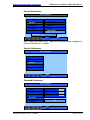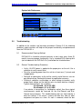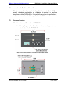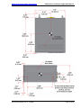
1
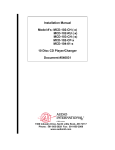
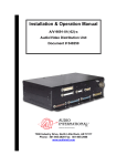
Installation and Operation
Manual
DVD-5x2-01-x
Dual Digital Video Disc Player
Document # 540356
(Model DVD-502-01-x shown)
7300 Industry Drive, North Little Rock, AR 72117
Phone: 501-955-2929 Fax: 501-955-2988
www.decraneaerospace.com
DeCrane Aerospace Audio International
DVD-5x2-01-x Installation & Operation Manual
Document Revision History
Rev. Level
Date
Description
IR
12/2007
A
2/2008
B
7/2008
C
12/2008
Initial Release
Updated Outline Drawings corrected weight & power
requirements.
Updated Reference Documents & Drawings, includes
addition of connector designator engraving.
Added J3 & J4, (BNC1 & BNC2), Section 3.7.5.
Separated “Instructions for Continued Airworthiness” and
“Troubleshooting” into Sections 5.0 and 6.0.
Added “routine cleaning” requirements to periodic scheduled
maintenance, Section 5.1.
Removed BNC references and changed to J3 & J4, per
Outline Drawing, Sections 3.7.5 & 3.8.
Clarified which connectors belong to which DVD slot. Upper
connectors J2 & J4 belong to the upper slot or DVD2. Lower
connectors J1 & J3 belong to the lower slot or DVD1,
Section 3.8.2.
Corrected the OP Mode Audio Setup, Section 4.4.
Updated Reference Drawings designator engraving, labeled
DVD slots, and corrected dimensions, Section 7.0.
Reference Documents
(or latest revision)
Description
Document #
525954 Rev A1
DVD-502-01-x Outline Drawing
525956 Rev A1
DVD-512-01-x Outline Drawing
Service Bulletin List
Service
Bulletin #
Subject
Manual
Revision
Revision
Date
Table of Illustrations
Section #
Description
Page #
2.4
Typical System Block Diagram
6
4.1
Front Panel Controls
15
6.1
Reference Drawings
34-38
PROPRIETARY INFORMATION NOTICE: Despite any other copyright notice, this document and
information disclosed herein contains confidential, proprietary designs owned by DeCrane
Aerospace Audio International. Neither this document nor the data contained herein shall be
reproduced, used, or disclosed to anyone without the written authorization of DeCrane Aerospace
Audio International.
Document # 540356, Rev C, 12/2008
Page 1 of 38
DeCrane Aerospace Audio International
DVD-5x2-01-x Installation & Operation Manual
Table of Contents
Section
1.0
1.1
1.2
1.3
1.4
Description
General Information. . . . . . . . . . . . . . . . . . . . . . . . . . . . . . . .
Introduction . . . . . . . . . . . . . . . . . . . . . . . . . . . . . . . . . . . . . . .
Purpose of the Equipment . . . . . . . . . . . . . . . . . . . . . . . . . . . .
Operational Features . . . . . . . . . . . . . . . . . . . . . . . . . . . . . . . .
Optional Equipment . . . . . . . . . . . . . . . . . . . . . . . . . . . . . . . . .
Page
3
3
3
3
4
2.1
2.2
2.3
2.4
Application. . . . . . . . . . . . . . . . . . . . . . . . . . . . . . . . . . . . . . . .
Typical Application . . . . . . . . . . . . . . . . . . . . . . . . . . . . . . . . . .
Operating Parameters. . . . . . . . . . . . . . . . . . . . . . . . . . . . . . . .
Media and Format Capabilities. . . . . . . . . . . . . . . . . . . . . . . . .
Typical System Block Diagram . . . . . . . . . . . . . . . . . . . . . . . .
4
4
5
5
6
3.0
Installation. . . . . . . . . . . . . . . . . . . . . . . . . . . . . . . . . . . . . . . .
3.1 Preparation. . . . . . . . . . . . . . . . . . . . . . . . . . . . . . . . . . . . . . . .
3.2 Unpacking and Inspection. . . . . . . . . . . . . . . . . . . . . . . . . . . . .
3.3 Cautions & Warnings. . . . . . . . . . . . . . . . . . . . . . . . . . . . . . . .
3.4 Wiring Requirements. . . . . . . . . . . . . . . . . . . . . . . . . . . . . . . . .
3.5 Physical Characteristics. . . . . . . . . . . . . . . . . . . . . . . . . . . . . .
3.6 Clearance and Separation Requirements. . . . . . . . . . . . . . . . .
3.7 Electrical Characteristics. . . . . . . . . . . . . . . . . . . . . . . . . . . . . .
3.8 Mating Connector Information. . . . . . . . . . . . . . . . . . . . . . . . . .
3.9 Pinout Assignments and Descriptions. . . . . . . . . . . . . . . . . . . .
3.10 Post Installation Test. . . . . . . . . . . . . . . . . . . . . . .. . . . . . . . . .
7
7
7
8
9
10
11
11
13
14
14
4.0
4.1
4.2
4.3
4.4
Operation. . . . . . . . . . . . . . . . . . . . . . . . . . . . . . . . . . . . . . . . .
Front Panel Controls. . . . . . . . . . . . . . . . . . . . . . . . . . . . . . . . .
Front Panel Control Functions. . . . . . . . . . . . . . . . . . . . . . . . .
Supported RS-485 and IR Commands. . . . . . . . . . . . . . . . . . .
Setup Menu Navigation. . . . . . . . . . . . . . . . . . . . . . . . . . . . . . .
15
15
16
18
20
5.1
5.2
5.3
Troubleshooting. . . . . . . . . . . . . . . . . . . . . . . . . . . . . . . . . . .
Recommended Cleaning Method . . . . . . . . . . . . . . . . . . . . . . .
General Troubleshooting Procedures . . . . . . . . . . . . . . . . . . .
Troubleshooting Chart . . . . . . . . . . . . . . . . . . . . . . . . . . . . . . .
32
32
32
33
6.0
Instructions for Continued Airworthiness . . . . . . . . . . . . . .
34
7.0
Reference Drawings. . . . . . . . . . . . . . . . . . . . . . . . . . . . . . . .
Dimensions and Connections: DVD-502-01-x. . . . . . . . . . . . . .
Dimensions and Connections: DVD-502-01-x. . . . . . . . . . . . . .
34
35
37
2.0
5.0
7.1
7.2
Document # 540356, Rev C, 12/2008
Page 2 of 38
DeCrane Aerospace Audio International
DVD-5x2-01-x Installation & Operation Manual
DVD-5x2-01-x
Dual Digital Video Disc Player
General Information
1.1
Introduction
This manual contains information for the proper installation and operation
of DeCrane Aerospace Audio International’s Dual Digital Video Disc
Player, Model # DVD-5x2-01-x. The “x” in the “-5x2” designates the
differences between units. The DVD-502-01-x is a base dual DVD unit.
The DVD-512-01-x has additional mounting brackets and a wider cover
bezel to support existing installations of past generation players. The “-x”
suffix in the model number designates the type of connector utilized; “-1” =
Positronic and “-2” = D-Subminiature. Also included are mechanical and
electrical characteristics of the unit.
1.2
Purpose of the Equipment
DeCrane Aerospace Audio International’s DVD-5x2-01-x is a high-quality
dual video disc player built to support the navigation through and playback
of up to two (2) DVD or CD Discs at the same time. This DVD player is
designed with maximum shock isolation and an attractive removable cover
bezel. Additionally, the DVD-5x2-01-x supports all DVD region codes for
comprehensive international operation.
DVD-5x2-01-x can be mounted in a cabinet or bulkhead. A unique
strapping feature allows up to four (4) similar devices to be used in the
same system at the same time for a total of eight (8) selectable players,
while maintaining independent control.
For installation ease, the DVD-512-01-x has been designed to replace any
DeCrane Aerospace Audio International DVD-411-01-x DVD Player.
1.3
Operational Features
Two (2) fully functional DVD disc drives
Supports standard commercial audio/video CD and audio/video
DVD (refer to Section 2.3 for a complete format list)
Capability to channel stereo analog audio, DTS, and industry
standard Digital sound through PCM
Supports all DVD region codes for international operation
NTSC Video Output
Easy-to-use front panel controls
Document # 540356, Rev C, 12/2008
Page 3 of 38
DeCrane Aerospace Audio International
DVD-5x2-01-x Installation & Operation Manual
Optional infrared remote control capability
High fidelity, differential analog audio output
Up to 45 advanced functions available for DeCrane Aerospace
Audio International'
s remote control or any DeCrane Aerospace
Audio International data bus device for complete system
customization
Full range frequency response
Nine (9) language and subtitle options (dependent upon usersupplied disc capabilities)
Easy to mount and connect
Compact, lightweight package
Multiple Forward and Reverse accelerated scanning speeds with
DVD video
Multiple Slow Forward and Reverse Speeds with DVD video
Slot-Fed Drives
1.4
Optional Equipment
The DVD-5x2-01-x can be optionally controlled by infrared remote or
DeCrane Aerospace Audio International’s touch screen panels, and it is
important to remember that some remote controls possess functions not
duplicated by the Unit’s front panel buttons, such as Menu and Set-Up.
While the DVD-5x2-01-x is a complete and fully functional standalone
DVD Player, it is strongly recommended that a remote control device also
be employed for thorough enjoyment of the Unit.
DeCrane Aerospace Audio International also offers a wide variety of
monitors, speakers, headphone jacks, video distribution devices, and
other equipment that will perfectly complement the DVD-5x2-01-x and will
be valuable and attractive additions to any cabin interior.
Contact your DeCrane Aerospace Audio International representative for
details.
2.0
Application
2.1
Typical Application
The DVD-5x2-01-x video output typically interfaces with a video monitor or
a video distribution device (i.e., AV-3232, VSS-0408, etc.). Additionally,
the DVD-5x2-01-x is capable of providing audio output to various audio
distribution devices (i.e., AV-3232, AI-LDC101, HDM-3 etc.)
Document # 540356, Rev C, 12/2008
Page 4 of 38
DeCrane Aerospace Audio International
2.2
DVD-5x2-01-x Installation & Operation Manual
Operating Parameters
Typically, the unit operates between +18 and +32 VDC with a power
consumption of less than 1A at +28 VDC. Video output is designed for 75
ohm termination. The unit drives 2 VRMS audio into not less than 600
ohm.
DVD-5x2-01-x provides NTSC video output based on disc format. Once a
DVD is inserted, the DVD-5x2-01-x will automatically begin playing the
disc. If power is interrupted (>200 ms) or power drops below +18 VDC
while a disc is playing, the player may shut down. When normal operating
power is restored, the DVD-5x2-01-x will automatically start playing. It
stops playback when the end of the disc is reached.
2.3
Media and Format Compatibilities
DVD-5x2-01-x is compatible with standard commercial audio/video CDs
and audio/video DVDs. Note that since DVD disc format standards are
constantly evolving, some DVD and CD discs may not play properly or
may cause the unit to malfunction. DeCrane Aerospace Audio
International does not guarantee the DVD-5x2-01-x is compatible with all
media or formats.
Compatible Recordable
Media Types
CD-R
CD-RW
DVD+R/+RW
DVD –R/-RW
Compatible Formats
Standard CD-Audio
Standard DVD-Video
VCD*
SVCD*
MP3 Audio
DVD [Plus]
Dual Disc
CD-Digital Audio (with CD text capability)
SACD, CD layer only
Multi-Session CD**
Mixed Mode CD**
CD Extra**
Copy Protected CD
12 cm Disc (8 cm with adapter only)
* Standard Video CDs are compatible, but those with DVD-like menus
may not function properly.
** ROM multi session CD, only the closed sessions are played. CD with
several sessions containing audio tracks, only the first audio session is
read/played. Mixed Mode CD, only audio tracks will be played.
Document # 540356, Rev C, 12/2008
Page 5 of 38
DeCrane Aerospace Audio International
DVD-5x2-01-x Installation & Operation Manual
Typical DVD Authoring programs are compatible and produce playable
movies. However, some programs may create menu structures or controls
that are not compatible, or do not display or function as intended.
2.4
Typical System Block Diagram
2.4.1 This unit is fully compatible with DeCrane Aerospace Audio
International’s proprietary RS-485 digital data bus system. It can be
configured for IR remote control utilizing DeCrane Aerospace Audio
International’s remote control unit AI-RC5-7xxxx and IFR-485.
2.4.2 The unit can also be configured for Touch Screen or Remote Panel
Control (i.e. entertainment control panels). The panels are on
DeCrane Aerospace Audio International’s proprietary RS-485
digital data bus system and configured to control the operational
features of the DVD-5x2-01-x.
2.4.3 This unit has a digital IR input that can be directly connected to the
digital output of an IFR-485 to allow for remote control on systems
that do not utilize a RS-485 control data bus.
Document # 540356, Rev C, 12/2008
Page 6 of 38
DeCrane Aerospace Audio International
3.0
DVD-5x2-01-x Installation & Operation Manual
Installation
3.1
Preparation
3.1.1
Careful consideration of the location of this and all other
audio/visual modules is necessary. Some of the items to be
considered in the design and layout of the aircraft cabin include:
• Space
• Available power supply
• Environmental conditions (temperature, humidity, etc.)
• Length of cable runs
• Location of other aircraft systems (oxygen delivery)
3.1.2 The DVD-5x2-01-x shall be installed to conform to the standards
designated by the customer, installing agency, and existing
conditions as to the unit location and type of installation.
3.1.3 Mounting screws are required to secure the unit. Mounting points
will vary depending on the kit used. Refer to Section 6.0, Reference
Drawings, for mounting hole diameters and configurations.
3.1.4 All headphone amplifiers and line level amplifiers should be located
no more than three (3) feet away from source equipment. Long
low-level audio runs may introduce noise into the audio signal.
3.1.5 The installing agency shall supply and fabricate all external cables
to the DVD-5x2-01-x. The length and routing of external cables
shall be carefully studied and planned before attempting installation
of the unit. Allow adequate space for installation of cable and
connectors. Mating connectors are the responsibility of the
installing agency. Correct pin assignments as outlined in Section
3.9 are the responsibility of the installing agency.
3.2
Unpacking and Inspection
3.2.1 Carefully open the packaging and remove the DVD-5x2-01-x. Verify
that all components have been included in the package per the
packing list. Inspect the unit for shipping damage.
3.2.2 If damage has occurred during shipping, a claim should be filed
with DeCrane Aerospace Audio International WITHIN 24 hours and
a Return Request Authorization Number shall be obtained from
DeCrane Aerospace Audio International by contacting the Repair
Department at 501-801-8101. Repackage the unit in its original
packaging materials and return it to DeCrane Aerospace Audio
International following instructions given by the DeCrane
Aerospace Audio International representative. Refer to the front
Document # 540356, Rev C, 12/2008
Page 7 of 38
DeCrane Aerospace Audio International
DVD-5x2-01-x Installation & Operation Manual
cover of this manual for address. If no return is necessary, retain
the packing list and the packing materials for storage.
3.2.3 Return only the core unit for replacement or service. Remove
and retain for reuse the bezel, installed rails and pigtail (if used) as
well as any mounting hardware.
3.3
Cautions & Warnings
3.3.1
It is important to do a pin-to-pin power and ground check on all
connectors. Ensure that power and ground are applied only
where specified. Damage to the unit may result if power or
ground is applied to the wrong points.
3.3.2
DO NOT connect or disconnect the unit while power is applied.
3.3.3
DO NOT remove any factory-installed screws. Damage to the unit
may result and void any warranties.
3.3.4
DO NOT drop the unit or subject it to strong shock. The unit
contains glass parts that may break or crack.
3.3.5
DO NOT place foreign objects into openings. Contact with foreign
objects may result in dangerous voltage or electric shock.
3.3.6
DO NOT place near strong magnetic fields, radiators or other
heat sources.
3.3.7
DO NOT use this unit other than for its intended purpose. Doing
so might lead to electric shock or injury.
3.3.8
DO NOT use near water, moisture, or volatile sprays. Do not use
any type of solvent when cleaning (surface damage may occur).
3.3.9
DO NOT look directly into the laser beam through the disc slot
opening. Eyesight may be damaged.
3.3.10 DO NOT place fingers in disc slot. Device may pinch fingers and
may cause injury.
3.3.11 DO NOT expose unit to sun or bright light. Damage to the sensor
may result.
3.3.12 The chassis material and structural design of this unit is such that
the unit is not capable of containing fire within the unit. This unit
does not provide for waterproof operation.
Document # 540356, Rev C, 12/2008
Page 8 of 38
DeCrane Aerospace Audio International
DVD-5x2-01-x Installation & Operation Manual
3.3.13 Operating temperature should not exceed –15C to +55C.
3.3.14 NO scheduled maintenance is required to ensure continued
airworthiness.
3.3.15 ESD (Electro Static Discharge) guidelines shall be followed.
3.4
Wiring Requirements
3.4.1 Introduction
The installing agency shall supply and fabricate all external cables.
The length and routing of external cables shall be carefully studied
and planned before attempting installation of the equipment. Allow
adequate space for installation of cable and connectors. Avoid
sharp bends and placing cables near aircraft control cables.
Maintain a minimum clearance of three (3) inches from any control
cable. If wiring is run parallel to combustible fluid or oxygen lines,
maintain a separation of six (6) inches between the lines.
3.4.2 Power Wires
All power and ground wires shall be in accordance with NEMA WC
27500, MIL-W-22759, or equivalent. Protect power wires with
circuit breakers or fuses located close to the electrical power
source bus.
3.4.3 Video Lines
Composite video connections shall be shielded coaxial cable in
accordance with the military specifications of M17/94-RG179.
3.4.4 DeCrane Aerospace Audio International’s Proprietary RS-485
Data Bus
3.4.4.1 The DVD-5x2-01-x is designed to interface with other
DeCrane Aerospace Audio International equipment via
DeCrane Aerospace Audio International’s proprietary RS485 serial data bus. The data bus shall be implemented
Document # 540356, Rev C, 12/2008
Page 9 of 38
DeCrane Aerospace Audio International
DVD-5x2-01-x Installation & Operation Manual
using a twisted shielded pair cable in accordance with MILW-22759. The wire size for the conductors in this cable
shall be 22 AWG, MINIMUM. Shield pins are available for
connecting data bus shields when required.
3.4.4.2 Refer to DeCrane Aerospace Audio International
document 650007 for RS-485 Serial Data Bus design
architecture.
3.4.5 Analog Audio Lines
DeCrane Aerospace Audio International recommends that all audio
wire connections be twisted shielded cable with the shield properly
grounded at the source (ideal practice). If shield cannot be
grounded at the source, then ground at the load end with opposite
end floating. Twisted shielded cable shall be in accordance with
MIL-W-22759.
3.5
Physical Characteristics
3.5.1 Dimensions and Weight
Physical Specifications DVD-502-01-X
Housing
Anodized Aluminum
Weight DVD-502-01-X
4.35 lb ±.25 lb / 1.97 kg ±.11 kg
Dimensions DVD-502-01-X
6.53" x 6.0" x 3.25"
(l x w x h)
16.69 cm x 15.24 cm x 8.26 cm
Note: Dimensions provided do not include cover bezel information.
Physical Specifications DVD-512-01-X
Housing
Anodized Aluminum
Weight DVD-512-01-X
4.90 lb ±.25 lb / 2.22 kg ±.11 kg
Dimensions DVD-512-01-X
9.17" x 7.17" x 3.25"
(l x w x h)
23.29 cm x 18.21 cm x 8.26 cm
Note: Dimensions provided do not include cover bezel information.
3.5.2 When mounting the unit, allow sufficient space for mating
connectors.
3.5.3 Allow a MINIMUM of one (1) inch of air space around the unit to
allow for proper air circulation. This unit has an internal fan and
ventilation holes in the chassis for cooling. Installation
recommendation requires 1-inch spacing from other components
Document # 540356, Rev C, 12/2008
Page 10 of 38
DeCrane Aerospace Audio International
DVD-5x2-01-x Installation & Operation Manual
and structures except the mounting surface for which the unit
should be in direct contact.
3.5.4 The cover bezel snaps easily on the DVD Player’s faceplate
without the need of special tools. The cover bezel does not require
mounting bracket attachments.
3.5.5 Bonding between chassis mounting point and airframe installation
to be <0.1 ohm resistance using <50 ohm impedance cable. No
surface prep is required due to conductive chassis (except front
bezel).
3.6
Clearance and Separation Requirements
When running cables, avoid sharp bends and placing cables near aircraft
control cables. Maintain a MINIMUM clearance of three (3) inches from
any control cable. If wiring is run parallel to combustible fluid or oxygen
lines, maintain a separation of six (6) inches between the lines.
3.7
Electrical Characteristics
3.7.1 Electrical Specifications:
Electrical
Power
In-Rush Peak
In-Rush Rise Time
In-Rush Return to 90%
Nominal
Operating Voltage Range
Data Bus Type
Audio Frequency Response
Audio Output
Audio Signal to Noise Ratio
Dynamic Range
Video Output
Video Input Format
Infrared Signal Input
900 mA @ +28 VDC
2 Amps
850 microseconds
20 msec
+18 to +32 VDC
DeCrane Aerospace Audio
International Proprietary RS-485
20 Hz – 20 Kkz +/- 3dB
2 VRMS (factory preset) into
600 ohm load
-90dB
96dB
1 V(p-p) into 75 ohm
Multi-Regional (NTSC)
+5 V digital logic level
3.7.2 The DVD-5x2-01-x utilizes one (1) 15-pin connector for electrical
connections, which provides power, data bus control, infrared input,
and three (3) address strapping pins and a strapping common for
unit identification on the RS-485 data bus and for IR control.
Document # 540356, Rev C, 12/2008
Page 11 of 38
DeCrane Aerospace Audio International
DVD-5x2-01-x Installation & Operation Manual
3.7.3 Infrared input provides a ground reference connection (-). For
optimum infrared signal transmission, this ground reference should
connect to the IFR-9A or IFR-485 module being utilized.
3.7.4 The three (3) address strap pins are able to be connected to the
strap common. This provides strapping configurations, allowing up
to four (4) identical units to be individually controlled on a system.
The RS-485 sub-address of each player in the unit is set by
strapping the appropriate ID STRAP pin to ID STRAP COMMON.
Each connector must have a unique strapped ID for proper control
of this unit via the RS-485 data bus or IR interface.
If both connectors are strapped with identical sub-address, the 2
individual players default to sub-address 0 and 1 respectively.
The RS-485 sub-address of this unit is based on ID Strapping as
suggested below:
ID Strap 4
ID Strap 3
ID Strap 2
Sub-Address
0
0
0
0
0
0
1
1
0
1
0
2
0
1
1
3
1
0
0
4
1
0
1
5
1
1
0
6
1
1
1
7
Note: A value of 1 indicates the associated ID STRAP pin is
connected ID STRAP COMMON. A value of 0 indicates the
associated ID STRAP pin is a No Connect.
3.7.5 The J3 and J4 video output connectors provides video outputs to
the video distribution system.
Document # 540356, Rev C, 12/2008
Page 12 of 38
DeCrane Aerospace Audio International
3.8
DVD-5x2-01-x Installation & Operation Manual
Mating Connector Information
3.8.1 Mating Connector assignment as follows:
Model #
DVD-502-01-1
DVD-502-01-2
DVD-512-01-1
DVD-512-01-2
Model #
DVD-502-01-x
DVD-512-01-x
J1 and J2 Connectors
Unit Connector
Mating Connector
RD15M10JV30 or
RD15F10JVL0
equivalent
(Positronic Industries)
(Positronic Industries)
DAMA-15P or equivalent
DAMA-15S
(ITT Cannon)
(ITT Cannon)
RD15M10JV30 or
RD15F10JVL0
equivalent
(Positronic Industries)
(Positronic Industries)
DAMA-15P or equivalent
DAMA-15S
(ITT Cannon)
(ITT Cannon)
J3 and J4 Video Output
Unit Connector
Mating Connector
AMP 523-31-5431
31-71013 or equiv. (Amphenol)
AMP 523-31-5431
31-71013 or equiv. (Amphenol)
Note: The connector information provided above is the same for both
DVD cards/slots.
3.8.2 Connector Locations
Note: Upper connectors J2 & J4 belong to the upper slot or DVD2. Lower
connectors J1 & J3 belong to the lower slot or DVD1.
Document # 540356, Rev C, 12/2008
Page 13 of 38
DeCrane Aerospace Audio International
3.9
DVD-5x2-01-x Installation & Operation Manual
Pinout Assignment and Descriptions
DVD-5x2-01-x
J1 and J2 Pinouts
Pin #
Description
1
+ 28 VDC Power Input
2
Ground
3
R+ Audio Output
4
R- Audio Output
5
L+ Audio Output
6
L- Audio Output
7
RS485 Data Bus A (HI)
8
RS485 Data Bus B (LO)
9
Infrared Digital Input +
10
Infrared Digital Input 11
ID Strap 2
12
ID Strap 3
13
ID Strap 4
14
ID Strap Common
15
“Pause Mode” Constant GND Input
3.10
Post Installation Test
Note that these steps should be taken with both DVD drives.
This section is designed to assist the user in determining whether the
DVD Player has been properly installed. First, before applying power,
ensure the unit is connected correctly, especially concerning Power and
Ground wiring. The audio signal output of the unit is generally connected
to cabin speaker systems in addition to headphone locations. Verify all
connections before supplying power to the unit.
There are no ON/OFF controls on the unit so ensure that +28 VDC power
has been connected. Normally if power is not properly connected, the
front panel controls’ backlighting will not be illuminated and the player will
not respond to any commands.
Activate monitors and speakers from the appropriate control panels. Audio
will be supplied through headphones and/or speakers per system design.
Make certain that the monitor(s) connected to the DVD Player are on and
functional.
Press the EJECT
button on the Front Panel Controls or by using a
remote control device. The disk will eject. Carefully slide and load a clean,
functional DVD disc into the slot. Be certain to load the disc correctly—
Document # 540356, Rev C, 12/2008
Page 14 of 38
DeCrane Aerospace Audio International
DVD-5x2-01-x Installation & Operation Manual
if the DVD has a sticker, it should be loaded with the sticker facing
up! Gently push the DVD into the slot.
The disc should begin loading, which will be indicated on the monitor
screen. If the disc does not start playing automatically after it has loaded,
then use the DVD Player’s front panel buttons or the handheld remote
control unit to select PLAY. DVD material should appear on the
appropriate monitor. This material is usually a menu, but this may vary,
depending on individual DVD configuration. For CDs, the tracks should be
listed on the side of the screen. Audio should channel through the
speaker/headphone system.
If sound cannot be immediately heard through speakers or headphones, it
may be that the volume is too low and should be increased appropriately.
Note that there are no audio controls on the DVD-5x2-01-x. Any desired
adjustments must be performed through other audio distribution devices.
If power is interrupted (>200 msec) or power drops below +18 VDC while
a disc is playing, the player may shut down. If a DVD disc is in the player,
the unit will begin playback from the beginning of the disc automatically.
4.0
Operation
4.1
Front Panel Controls
Document # 540356, Rev C, 12/2008
Page 15 of 38
DeCrane Aerospace Audio International
DVD-5x2-01-x Installation & Operation Manual
From left to right, the buttons are:
CHANGE
REVERSE
STOP
4.2
PAUSE
FORWARD
EJECT
PLAY
Front Panel Control Functions:
CHANGE BUTTON
The Change Button causes the front panel to alternate control between
DVD 1 and DVD 2.
The Change Button is active when the DVD Player is powered on and not
in Standby Mode. If the Change Button is pressed while the unit is in
Standby Mode, the unit will power up, then press the Change Button
again and the unit will respond.
REVERSE BUTTON
During movie or audio play, press the Reverse Button to skip to the
beginning of the previous chapter or CD track. The Fast/Slow Reverse
Button is functionally dependent on the current mode of the DVD Player,
and the media type being played.
Pressing and holding the Reverse Button will place the DVD Player in
Fast Reverse x8 Mode with no audio output. Play will resume when
Reverse Button is released.
The Reverse Button is active when the DVD Player is powered on and not
in Standby Mode. If the Reverse Button is pressed while the unit is in
Standby Mode, the unit will power up, then press the Reverse Button
again and the unit will respond.
FORWARD BUTTON
During movie or audio play, press the Forward Button to skip to the
beginning of the next chapter or CD track. The Forward Button is
Document # 540356, Rev C, 12/2008
Page 16 of 38
DeCrane Aerospace Audio International
DVD-5x2-01-x Installation & Operation Manual
functionally dependent on the current mode of the DVD Player, and the
media type played.
Pressing and holding the Forward Button once will place the DVD Player
in Fast Forward x8 Mode with no audio output. Play will resume when the
Forward Button is released.
The Forward Button is active when the DVD Player is powered on and not
in Standby Mode. If the Forward Button is pressed while the unit is in
Standby Mode, the unit will power up, then press the Forward Button
again and the unit will respond.
EJECT BUTTON
The Eject Button allows the user to access the disc. After pressing the
Eject Button it is then possible to retrieve the disc from the DVD Player.
Note that the disc will slide out on its own. It is not necessary to force the
disc to eject from the DVD Player.
The Eject Button is active when the DVD Player is powered on and not in
Standby Mode. If the Eject Button is pressed while the unit is in Standby
Mode, the unit will power up, then press the Eject Button again and the
DVD or CD will respond.
STOP BUTTON
Press the Stop Button once during playback to place the DVD Player in
Hold Mode. The stops playback and causes a blue screen to be
displayed. Pressing the Play Button at this point will resume playback from
the Held point.
The Stop Button is active when the DVD Player is powered on and not in
Standby Mode. If the Stop Button is pressed while the unit is in Standby
Mode, the unit will power up, then press the Stop Button again and the
DVD or CD will respond.
PLAY BUTTON
The Play Button allows the user to begin or resume normal Playback
when the DVD Player is in the following modes: Stop, Pause, Forward,
and Rewind.
Document # 540356, Rev C, 12/2008
Page 17 of 38
DeCrane Aerospace Audio International
DVD-5x2-01-x Installation & Operation Manual
The Play Button can be used to access the DVD Root Menu at any time,
by pressing and holding the Play button.
The Play Button is active when the DVD Player is powered on and not in
Standby Mode. If the Play Button is pressed while the unit is in Standby
Mode, the unit will power up, then press the Play Button again and the
DVD or CD will respond.
PAUSE BUTTON
Press the Pause Button to place the DVD Player in PAUSE Mode.
The Step Mode becomes available when the DVD Player is in PAUSE
mode and playing a DVD. Normal Playback can be resumed by pressing
the Play Button.
The Pause Button is active when the DVD Player is powered on and not
in Standby Mode. If the Pause Button is pressed while the unit is in
Standby Mode, the unit will power up, then press the Pause Button again
and the DVD or CD will respond.
OLED SCREEN
Screen Saver is active after 30 seconds of inactivity. OLED goes blank
after 1 minute of Screen Saver Mode. Any press of a button wakes up the
player, making the main screen active. An additional button must be
pushed to perform a function.
4.3
Setup Menu Control Functions
•
The Setup Menu will display on the video output of the player.
•
To access the DVD Player’s Setup Menu push and hold the Stop
button.
•
If the unit is inactive for 30 seconds, the unit will require any button
to be pushed to remove the unit from Sleep Mode. An additional
button must be pushed to perform a function.
•
To navigate Left push the Reverse Button, until the desired
selection is highlighted.
•
To navigate Right push the Forward Button, until the desired
selection is highlighted.
Document # 540356, Rev C, 12/2008
Page 18 of 38
DeCrane Aerospace Audio International
DVD-5x2-01-x Installation & Operation Manual
•
To navigate Up hold the Reverse Button, until the desired selection
is highlighted.
•
To navigate Down hold the Forward Button, until the desired
selection is highlighted.
•
To turn items On or Off, select the options then hit Play or Forward.
The Checkmarks and Light Bulbs indicate whether items are On or
Off.
Certain selections will make access to other selections
inaccessible. All active selections are indicated by blue boxes. All
inactive selections are indicated by grey boxes.
•
•
To Exit the Setup Menu, press Stop.
Document # 540356, Rev C, 12/2008
Page 19 of 38
DeCrane Aerospace Audio International
4.4
DVD-5x2-01-x Installation & Operation Manual
Setup Menu Navigation
Main Page Menu
MAIN PAGE
General
Speaker
Audio
Play Mode
Preferences
Enter
General Menu
GENERAL
Angle Mark
OSD Language
Enter
Document # 540356, Rev C, 12/2008
Page 20 of 38
DeCrane Aerospace Audio International
DVD-5x2-01-x Installation & Operation Manual
Angle Mark Selections
The ANGLE Mark allows the User to change angles on DVD Videos that
offer angle selection.
GENERAL
Angle Mark
ON
OSD Language
Off
Enter
OSD Language Selections
The OSD Language allows the user to change the language displayed in
the Setup Menu. There are nine (9) language selections.
GENERAL
Angle Mark
English
OSD Language
Spanish
French
Portuguese
Italian
Enter
GENERAL
Angle Mark
Italian
OSD Language
German
Chinese
Japanese
Korean
Document # 540356, Rev C, 12/2008
Page 21 of 38
DeCrane Aerospace Audio International
DVD-5x2-01-x Installation & Operation Manual
Speaker Setup Menu
MAIN PAGE
General
Speaker
Audio
Play Mode
Preferences
Enter
Downmix Speaker Setup
The Lt/Rt mode is not supported by the DVD-5x2-01-x and must not be
selected.
The Stereo mode must be made active for the DVD-5x2-01-x. Correct
audio playback from the DVD-5x2-01-x may not occur if this mode is not
selected.
The Off mode is not supported by the DVD-5x2-01-x and must not be
selected. Any functions that are enabled by selecting this setting are not
supported by the DVD-5x2-01-x.
SPEAKER SETUP
Downmix
Lt/Rt
Center
Stereo
Rear
Off
SubWoofer
Center Delay
Enter
Document # 540356, Rev C, 12/2008
Page 22 of 38
DeCrane Aerospace Audio International
DVD-5x2-01-x Installation & Operation Manual
Bass Speaker Setup
SPEAKER SETUP
SubWoofer
ON
Center Delay
Off
Rear Delay
Test Tone
Bass
Enter
Audio Setup Menu
MAIN PAGE
General
Speaker
Audio
Play Mode
Preferences
Enter
OP Mode Audio Setup
The Line Out mode is the recommended setting.
The RF Remod provides heavy compression, with no scaling allowed.
AUDIO SETUP
OP Mode
Line Out
Compression
RF Remod
Pro Logic
Enter
Document # 540356, Rev C, 12/2008
Page 23 of 38
DeCrane Aerospace Audio International
DVD-5x2-01-x Installation & Operation Manual
Compression Audio Setup
The Compression Audio will compress or expand the dynamic range of
the signal depending on its content. This can be adjusted to the user’s
preference.
AUDIO SETUP
OP Mode
Compression
Pro Logic
Full
-3/4
-1/2
--
Full
-3/4
-1/2
--
-Off
-Off
1/4
1/4
Enter
Pro Logic Audio Setup
Pro Logic is an audio post processing technique for audio data which
contains the Pro Logic information.
AUDIO SETUP
OP Mode
On
Compression
Off
Pro Logic
Auto
Enter
Document # 540356, Rev C, 12/2008
Page 24 of 38
DeCrane Aerospace Audio International
DVD-5x2-01-x Installation & Operation Manual
Play Mode Selection Menu
Shuffle mode enables the playable tracks or chapters to be played in a
random order.
Repeat mode allows selection of chapter or title to repeat.
MAIN PAGE
General
Speaker
Audio
Play Mode
Preferences
Enter
PLAY MODE SELECTION
Shuffle
Off
Repeat
Off
Enter
Document # 540356, Rev C, 12/2008
Page 25 of 38
DeCrane Aerospace Audio International
DVD-5x2-01-x Installation & Operation Manual
Preferences Menu
MAIN PAGE
General
Speaker
Audio
Play Mode
Preferences
Enter
TV Display Preferences
The User can choose to display the video they are watching in
Normal /Pan Scan, Normal/Letter Box, or Wide Screen.
PREFERENCES
TV Display
Normal / PS
Audio
Normal/LB
Subtitle
Wide
Disc Menu
Locale
Enter
Document # 540356, Rev C, 12/2008
Page 26 of 38
DeCrane Aerospace Audio International
DVD-5x2-01-x Installation & Operation Manual
Audio Preferences
This option allows the User to change the preferred audio language if
available on the DVD. There are nine (9) language selections.
PREFERENCES
TV Display
English
Audio
Spanish
Subtitle
French
Disc Menu
Portuguese
Locale
Italian
Enter
PREFERENCES
TV Display
Italian
Audio
German
Subtitle
Chinese
Disc Menu
Japanese
Locale
Korean
Enter
Document # 540356, Rev C, 12/2008
Page 27 of 38
DeCrane Aerospace Audio International
DVD-5x2-01-x Installation & Operation Manual
Subtitle Preferences
This option allows the User to change the preferred displayed subtitle if
available on the DVD. There are nine (9) language selections.
PREFERENCES
TV Display
English
Audio
Spanish
Subtitle
French
Disc Menu
Portuguese
Locale
Italian
Enter
PREFERENCES
TV Display
Italian
Audio
German
Subtitle
Chinese
Disc Menu
Japanese
Locale
Korean
Enter
Document # 540356, Rev C, 12/2008
Page 28 of 38
DeCrane Aerospace Audio International
DVD-5x2-01-x Installation & Operation Manual
Disc Menu Preferences
This option allows the User to change the preferred DVD menu language
if available on the DVD. There are nine (9) language selections.
PREFERENCES
TV Display
English
Audio
Spanish
Subtitle
French
Disc Menu
Portuguese
Locale
Italian
Enter
PREFERENCES
TV Display
Italian
Audio
German
Subtitle
Chinese
Disc Menu
Japanese
Locale
Korean
Enter
Document # 540356, Rev C, 12/2008
Page 29 of 38
DeCrane Aerospace Audio International
DVD-5x2-01-x Installation & Operation Manual
Locale Preferences
This option allows the User to specify the end user market. There are
seven (7) language selections.
PREFERENCES
Locale
China
Parental
France
Defaults
Hong Kong
Password
Japan
System Info
Taiwan
Enter
PREFERENCES
Locale
Hong Kong
Parental
Japan
Defaults
Taiwan
Password
GBR
System Info
USA
Enter
Note: The parental definition is dependent on the country setting.
Document # 540356, Rev C, 12/2008
Page 30 of 38
DeCrane Aerospace Audio International
DVD-5x2-01-x Installation & Operation Manual
Parental Preferences
PREFERENCES
Locale
5
Parental
6 PG-R
Defaults
7 NC-17
Password
8 Adult
System Info
No Parental
Password
Enter
1-9
Note: Default password “3308” needs to be entered before navigation of
Parental Preferences is allowed.
Defaults Preferences
PREFERENCES
Locale
Parental
Defaults
Password
System Info
Enter
Password Preferences
PREFERENCES
Locale
Old Password:
Parental
New Password:
Defaults
Confirm:
Password
System Info
EXIT
Enter
Document # 540356, Rev C, 12/2008
Page 31 of 38
DeCrane Aerospace Audio International
DVD-5x2-01-x Installation & Operation Manual
System Info Preferences
PREFERENCES
Locale
Parental
Defaults
Password
Baseline:
Date:
MPEG Sw:
Boot Sw:
Engine Sw:
DataPath Sw:
System Info
DVDV4a
12.05.06
i06.19.00
b05.47.00
E1.10.25
V11.23
EXIT
Enter
5.0
Troubleshooting
In addition to the cautions and warnings provided in Section 3.3, the following
guidelines and instructions will help ensure proper functionality and performance
from the DVD-5x2-01-x.
5.1
Recommended Cleaning Method
DVD-5x2-01-x should be cleaned routinely at least once every three (3)
months to ensure proper functionality. Use a standard DVD cleaning disc
(not included with the DVD-5x2-01-x) and follow the listed directions.
5.2
General Troubleshooting Procedures
•
•
•
•
Verify +28 VDC power is applied to the proper pins on the unit. Use a
voltmeter to verify correct level.
Reset by removing power from the unit for at least one (1) minute and
reapply power.
Recheck all connections to the unit for security and all harness runs for
possible pinching. Recheck all pinouts for application accuracy.
Utilizing a voltmeter, oscilloscope, or other voltage instrument, verify
proper input voltage on the data bus pins to check data bus integrity.
Typical measurements are as follows:
A to Ground : 4.0 to 4.5 VDC
B to Ground : 0.1 to 0.2 VDC
If any device is transmitting (i.e., holding bus active), then these typical
measurements would be reversed for the A-to-Ground and B-toGround measurements. This troubleshooting tool can help indicate a
data bus lockup. If this occurs, remove the data bus from all other
equipment one piece at a time. As each is removed, check the bus
Document # 540356, Rev C, 12/2008
Page 32 of 38
DeCrane Aerospace Audio International
•
5.3
DVD-5x2-01-x Installation & Operation Manual
status to see if it is now functioning properly. Once you have removed
the piece or pieces of offending equipment, disconnect power and
then reconnect everything but the suspect component, reapply power
and test the functionality of the unit.
The RS-485 data bus is a bi-directional bus that does not have a ‘bus
controller’. The bus uses a differential digital signal that will transmit
only when commands are entered via switch selection or other system
synchronizing commands. The “A” leg of the bus is HI and the “B” leg
LO.
Troubleshooting Chart
Problem
No picture
Possible Cause
Unit is improperly installed
•
Verify +28 VDC power and video
input is present
•
Insert DVD in source unit
Unit is improperly installed
•
•
Audio system not powered
or active
Apply power to Monitor
Verify +28 VDC power and audio
input is present
•
Verify audio system is in active
mode
•
No disc in source unit
No power to Monitor
No sound
Solution
Volume too low
Disc not in device
•
Increase volume to acceptable
level
Insert a disc into device
Disc upside down or not
aligned in guide
•
Reposition disc
Incompatible disc in device
•
Replace disc with compatible one
Dirty Disc
•
Clean the disc
Parental lock activated
•
Change or cancel parental lock
feature
No power
Poor video quality
Menu on the monitor
Circuit breaker has opened
Poor DVD quality
•
•
•
Exit the current menu
Reset circuit breaker
Replace DVD
•
Buttons not
operating
Noise being introduced
into system
Moisture may have
condensed inside unit.
Move source equipment closer to
monitor or distribution modules
Allow unit to warm to room
temperature and moisture has
evaporated.
Remove foreign object
Playback not
functioning
DVD disc cannot be
loaded
Document # 540356, Rev C, 12/2008
Foreign object in disc slot
•
•
Page 33 of 38
DeCrane Aerospace Audio International
6.0
DVD-5x2-01-x Installation & Operation Manual
Instructions for Continued Airworthiness
Other than a routine cleaning (instructions listed above in Section 5.1), no
periodic scheduled maintenance or calibration is required for continued
airworthiness of the DVD-5x2-01-x. If the unit fails to perform to specifications, it
must be removed and serviced by a qualified service facility.
7.0
Reference Drawings
7.1
Dimensions and Connections: DVD-502-01-x
The following diagrams show the unit dimensions, mounting locations, and
connector locations for the DVD-502-01-x.
Note: These measurements include the front cover bezel.
Document # 540356, Rev C, 12/2008
Page 34 of 38
DeCrane Aerospace Audio International
Document # 540356, Rev C, 12/2008
DVD-5x2-01-x Installation & Operation Manual
Page 35 of 38
DeCrane Aerospace Audio International
7.2
DVD-5x2-01-x Installation & Operation Manual
Dimensions and Connections: DVD-512-01-x
The following diagrams show the unit dimensions, mounting locations, and
connector locations for the DVD-512-01-x.
Note: This measurement is of the front cover bezel.
Document # 540356, Rev C, 12/2008
Page 36 of 38
DeCrane Aerospace Audio International
Document # 540356, Rev C, 12/2008
DVD-5x2-01-x Installation & Operation Manual
Page 37 of 38