1
General Specification
Electrical/Electronic
EMC-CS-2009.1
Electromagnetic Compatibility Specification
For Electrical/Electronic
Components and Subsystems
Foreword
This engineering specification addresses Electromagnetic Compatibility (EMC) requirements for
electrical/electronic (E/E) components and subsystems for Ford Motor Company (FMC). This
specification is the direct link from ARL-09-0466. These requirements have been developed to assure
compliance with present and anticipated regulations in addition to customer satisfaction regarding the
EMC of vehicle E/E systems. This specification replaces ES-XW7T-1A278-AC.
EMC-CS-2009 is applicable for all E/E components/subsystems slated for use on 2013 Ford vehicle
programs in addition to E/E component/subsystems whose commercial agreements are signed after
October 1, 2009.
EMC-CS-2009 is available for download from the Ford EKB in addition to www.fordemc.com
Corrections and/or editorial updates to this specification will be made as required and without prior
notification to the user. It is recommended that the user verify they have the latest version of the
specification prior to application to their E/E component/subsystem.
Information regarding differences between these specifications may be found at http://www.fordemc.com
Date
Version
9/30/2009
0
2/11/2010
1
February 11, 2010
Revision
Initial Release of Specification
Annex I updated to correct errors in measurement procedure
RE 310 flow chart corrections
CE 410 trigger setting correction
CI 280 requirements for metallic connectors
Corrections in tolerance requirements for certain tests
Numerous editorial corrections.
Corrected errors in Tables 16-1 and F-1 to align requirements.
Updates to Figures G-1 and G-3 in Annex G.
Requirement revisions for Artificial Networks
Printed copies are uncontrolled
EMC-CS-2009.1
Table of Contents:
Foreword......................................................................................................................................................................................1
1.0
Scope ...............................................................................................................................................................................6
2.0
References........................................................................................................................................................................7
3.0
Abbreviations, Acronyms, Definitions, & Symbols ........................................................................................................8
4.0
Common Test Requirements..........................................................................................................................................11
5.0
Additional Requirements ...............................................................................................................................................12
6.0
Requirement Applicability.............................................................................................................................................13
7.0
Radiated RF Emissions: RE 310....................................................................................................................................15
8.0
Conducted RF Emissions: CE 420.................................................................................................................................24
9.0
Conducted Emissions: CE 421.......................................................................................................................................26
10.0 Conducted Transient Emissions: CE 410.......................................................................................................................29
11.0 RF Immunity: RI 112, RI 114, RI 115..........................................................................................................................31
12.0 Magnetic Field Immunity: RI 140 .................................................................................................................................46
13.0 Coupled Immunity: RI 130 ............................................................................................................................................50
14.0 Coupled Immunity: RI 150 ............................................................................................................................................53
15.0 Immunity from Continuous Power Line Disturbances: CI 210 .....................................................................................56
16.0 Immunity from Transient Disturbances: CI 220 ...........................................................................................................59
17.0 Immunity from Power Cycling: CI 230 ........................................................................................................................64
18.0 Immunity to Ground Voltage Offset: CI 250................................................................................................................67
19.0 Immunity to Voltage Dropout: CI 260..........................................................................................................................72
20.0 Immunity to Voltage Overstress: CI 270 ......................................................................................................................79
21.0 Electrostatic Discharge: CI 280 ....................................................................................................................................80
Annex A (Normative): Field Calibration Procedure for ALSE Method Bands 6 and 7).......................................................86
Annex B (Normative): Modulation and Leveling Requirements for RI 112, RI 114 and RI 115 ........................................91
Annex C (Normative): Mode Tuning Chamber Calibration ................................................................................................93
Annex D (Normative): CI 220 Transient Waveform Descriptions......................................................................................100
Annex E (Normative): Transient Waveform Application..................................................................................................109
Annex F
(Normative): Transient Test Generator................................................................................................................111
Annex G (Normative): Load Simulator Requirements.......................................................................................................114
Annex H (Normative): RI 130, RI 150 Test Fixture and Application................................................................................118
Annex I
(Normative): Method for Determining Correction Factor for CE 421................................................................120
List of Figures
Figure 7-1: RE 310 Test Antenna Cable Configuration (excludes Rod antenna) .....................................................................18
Figure 7-2: RE 310 Test Setup (EU1, G1) DUTs with Selected Wiring in Engine Compartment ...........................................18
Figure 7-3: Recommended Process for Assessing DUT Emissions per RE 310 Level 1 Requirements ..................................22
Figure 7-4: Recommended Process for Assessing DUT Emissions to RE310 Level 2 Requirements ....................................23
Figure 9-1: CE 421 Conducted Emissions Requirements.........................................................................................................26
Figure 9-2: CE 421 Test Setup .................................................................................................................................................27
Figure 9-3: Typical Correction Factor for a CISPR 25 Artificial Network ..............................................................................27
Figure 10-1: CE 410 Transient Emissions Test ........................................................................................................................30
Figure 11-1: RI 112 Requirements using Bulk Current Injection (BCI)...................................................................................33
© Copyright Ford Motor Company – All Rights Reserved
February 11, 2010
Page 2 of 121
EMC-CS-2009.1
Figure 11-2: RI 112 DUT Harness Configurations...................................................................................................................35
Figure 11-3: RI 114 ALSE Test Setup (1000 – 2000 MHz) excluding Bands 6 and 7.............................................................37
Figure 11-4: RI 114 ALSE Test Setup for Bands 6 and 7 .........................................................................................................39
Figure 11-5: RI 115 Test Setup.................................................................................................................................................42
Figure 11-6: RI 115 Setup for Calibration................................................................................................................................43
Figure 11-7: RI 115 Antenna positioning for testing the harness ..............................................................................................45
Figure 12-1: RI 140 Magnetic Field Immunity Requirements..................................................................................................46
Figure 12-2: RI 140 Magnetic Immunity Test Setup: Radiating Loop .....................................................................................48
Figure 12-3: RI 140 Magnetic Immunity Test Setups for Helmholtz Coil ...............................................................................49
Figure 13-1: RI 130 Default Test Setup....................................................................................................................................51
Figure 14-1: RI 150 Coupled Immunity Requirements ............................................................................................................53
Figure 14-2: RI 150 Test Setup.................................................................................................................................................54
Figure 15-1: CI 210 Requirements ...........................................................................................................................................56
Figure 15-2: CI 210 Test Setup.................................................................................................................................................57
Figure 15-3: CI 210 AC Stress Level (US) Superimposed on DUT Supply Voltage (UP) ........................................................58
Figure 16-1: CI 220 Test Setup for Devices with a Single Power Supply Circuit ....................................................................60
Figure 16-2: CI 220 Test Setup for Devices with Two Power Supply Connections.................................................................61
Figure 16-3: CI 220 Test Setup for Devices with Input Circuits ..............................................................................................61
Figure 16-4: CI 220 Test Setup Detail (Input Circuits with Remote External Pull-Up Resistor) .............................................62
Figure 16-5: CI 220 Test Setup for Application of Pulse G1....................................................................................................62
Figure 16-6: CI 220 Test setup for Application of Pulse G2 .....................................................................................................62
Figure 17-1: CI 230 Power Cycling Waveforms and Timing Sequence...................................................................................65
Figure 17-2: CI 230 Power Cycling Test Setup ........................................................................................................................66
Figure 18-1: CI 250 Requirements (Continuous Disturbances)................................................................................................67
Figure 18-2: CI 250 Transient Pulse Detail ..............................................................................................................................68
Figure 18-3: CI 250 Transient Pulse Delay Detail.....................................................................................................................68
Figure 18-4: CI 250 Requirements (Transient Disturbance Sequence) .....................................................................................68
Figure 18-5: CI 250 Test Setup for Ground Offset of DUT .....................................................................................................70
Figure 18-6: CI 250 Signal Source Requirements .....................................................................................................................70
Figure 19-1: CI 260 Waveform A (Voltage Dropout: High) ....................................................................................................73
Figure 19-2: CI 260 Waveform B (Voltage Dropout: Low) .....................................................................................................73
Figure 19-3: CI 260 Waveform C (Single Voltage Dropout) ...................................................................................................74
Figure 19-4: CI 260 Waveform D (Voltage Dip) .....................................................................................................................74
Figure 19-5: CI 260 Waveform E (Battery Recovery)..............................................................................................................75
Figure 19-6: CI 260 Waveform F (Random Bounce) ...............................................................................................................75
Figure 19-7: CI 260 Waveform F (Expanded)..........................................................................................................................76
Figure 19-8: CI 260 Test Setup Detail for Waveforms A , B and C.........................................................................................76
Figure 19-9: CI 260 Test Setup Detail for Waveforms D and E...............................................................................................77
Figure 19-10: CI 260 Test Setup for Waveform F....................................................................................................................77
Figure 21-1: CI 280 ESD Handling Test Setup ........................................................................................................................82
Figure 21-2: CI 280 ESD Powered Test Setup .........................................................................................................................83
Figure 21-3: CI 280 Test setup ( Communication Bus Connection Requirements ).................................................................84
© Copyright Ford Motor Company – All Rights Reserved
February 11, 2010
Page 3 of 121
EMC-CS-2009.1
Figure A-1: Field Probe (Type A) Positioning Requirements (RI 114, Bands 6 and 7) ...........................................................88
Figure A-2: Field Probe (Type B) Positioning Requirements (RI 114, Bands 6 and 7) ...........................................................89
Figure A-3: Receive Antenna Positioning Requirements (RI 114, Bands 6 and 7) ...................................................................90
Figure B-1: RF Immunity Peak Conservation Profile................................................................................................................91
Figure B-2: RF Immunity Generic Leveling/Dwell Process......................................................................................................92
Figure B-3: RF Immunity Example of Combined CW and AM Dwell ....................................................................................92
Figure C-1: RI 114 Reverberation Test Configuration (Mode Tuning).....................................................................................99
Figure D-1: Simplified Automotive Circuit for Transient Immunity......................................................................................100
Figure D-2: CI 220 Pulse A1 Composite Waveform ..............................................................................................................101
Figure D-3: CI 220 Pulse A2-1 Pulse Characteristics.............................................................................................................101
Figure D-4: CI 220 Pulse A2-2 Pulse Characteristics.............................................................................................................102
Figure D-5: CI 220 Pulse C Characteristics............................................................................................................................103
Figure D-6: CI 220 Pulse E Characteristics ............................................................................................................................104
Figure D-7: CI 220 Pulse F1 Characteristics ..........................................................................................................................104
Figure D-8: CI 220 Pulse F2 Pulse Characteristics.................................................................................................................105
Figure D-9: CI 220 Pulse G1 Characteristics..........................................................................................................................105
Figure D-10: CI 220 Pulse G2 Characteristics........................................................................................................................106
Figure D-11: CI 220 Mode 2 Characteristics..........................................................................................................................107
Figure D-12: CI 220 Mode 3 Characteristics..........................................................................................................................108
Figure F-1: Transient Generator Circuit for RI 130 and CI 220 .............................................................................................111
Figure F-2: Transient Generator (External Connections) .......................................................................................................112
Figure G-1: Load Simulator (Typical Design)........................................................................................................................115
Figure G-2: Load Simulator CAN Interface Circuit Design Requirements ............................................................................116
Figure G-3: Load Simulator Test setup ...................................................................................................................................117
Figure H-1: RI 130/150 Test Fixture (Top View)...................................................................................................................118
Figure H-2: RI 130/150 Test setup ( Default DUT Wire Location ).......................................................................................118
Figure H-3: RI 130/150 Test Setup ( DUT with Dedicated Return Wire ) ..............................................................................119
Figure H-4: RI 130/150 Test setup ( Configuration for a Twisted Wire Pair ) ........................................................................119
Figure H-5: RI 130/150 Test setup ( Configuration for Shielded Twisted Wire Pair )............................................................119
Figure I-1: CE 421 Test Setup using Standard CISPR 25 Artificial Network ........................................................................121
List of Tables
Table 1-1: Vehicle Level EMC Requirements............................................................................................................................6
Table 4-1: Permissible Tolerances............................................................................................................................................12
Table 4-2: Environmental Test Conditions...............................................................................................................................12
Table 6-1: Requirement Selection Matrix.................................................................................................................................14
Table 7-1: RE 310 Level 1 Requirements.................................................................................................................................15
Table 7-2: RE 310 Level 2 Requirements.................................................................................................................................16
Table 7-3: RE 310 Measurement System Setup Requirements (Bands EU1, G1)....................................................................19
Table 7-4: RE 310 Measurement System Setup Requirements (All Bands except M1, M2, M3, EU1, G1)............................20
Table 7-5: RE 310 Measurement System Setup Requirements (Bands M1, M2, M3) .............................................................20
Table 8-1: CE 420 Conducted Emissions Requirements ..........................................................................................................24
Table 9-1: CE 421 Measurement System Setup Requirements ................................................................................................28
Table 11-1: RF Immunity Acceptance Criteria..........................................................................................................................31
© Copyright Ford Motor Company – All Rights Reserved
February 11, 2010
Page 4 of 121
EMC-CS-2009.1
Table 11-2: RF Immunity Test Frequency Steps .......................................................................................................................32
Table 11-3: RI 114 Requirements ( 400 – 3100 MHz ) ............................................................................................................36
Table 11-4: RI 115 Requirements for hand portable transmitters.............................................................................................41
Table 11-5: RI 115 Separation Distances and Antenna Positioning .........................................................................................41
Table 12-1: RI 140 Test Frequency Requirements ...................................................................................................................47
Table 13-1: RI 130 Coupled Immunity Requirements..............................................................................................................50
Table 14-1: RI 150 Test Frequency Requirements ....................................................................................................................55
Table 15-1: CI 210 Test Frequency Requirements ....................................................................................................................58
Table 16-1: CI 220 Transient Immunity Requirements ............................................................................................................59
Table 17-1: CI 230 Power Cycling Requirements ....................................................................................................................64
Table 18-1: CI 250 Acceptance Criteria (Continuous and Transient Disturbances).................................................................67
Table 18-2: CI 250 Delay Time Sequences 1 - 4 ......................................................................................................................69
Table 18-3: CI 250 Test Frequency Requirements ....................................................................................................................71
Table 19-1: CI 260 Voltage Dropout Requirements .................................................................................................................72
Table 20-1: CI 270 Requirements for Voltage Overstress........................................................................................................79
Table 21-1: CI 280 ESD Requirements: Handling (unpowered) .............................................................................................80
Table 21-2: CI 280 ESD Requirements: Powered (all component surfaces) ............................................................................81
Table C-1: Independent Samples and Frequencies for RI 114 Reverberation Method..............................................................98
Table D-1: CI 220 Mode 1 Characteristics .............................................................................................................................107
Table F-1: CI 220 Transient Generator Switch Settings.........................................................................................................112
Table F-2: CI 220 Transient Generator ( P&B Relay Specifications ) ...................................................................................113
© Copyright Ford Motor Company – All Rights Reserved
February 11, 2010
Page 5 of 121
EMC-CS-2009.1
1.0
Scope
This engineering specification defines the Electromagnetic Compatibility (EMC) requirements, test methods and test
procedures for electrical/electronic (E/E) components and subsystems used by Ford Motor Company (FMC) including
associated vehicle brands.
1.1
Purpose of the Specification
The purpose of this engineering specification is to ensure vehicle Electromagnetic Compatibility. This specification presents
EMC requirements and test methods that have been developed for E/E components and subsystems independent of the
vehicle. The purpose of component and subsystem testing is the pre-qualification of EMC at a time when representative
vehicles are not yet available.
1.2
Vehicle Level Requirements
In addition to meeting the requirements specified herein, E/E components and subsystems, when installed in the vehicle, shall
also comply with all relevant vehicle level EMC requirements including those listed in Table 1-1.
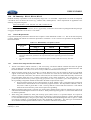
Table 1-1: Vehicle Level EMC Requirements
ARL 09-0409
ARL 09-0410
ARL 09-0411
ARL 09-0414
ARL 09-0419
ARL 09-0422
ARL 09-0425
ARL 09-0426
ARL 09-0433
ARL 09-0464
ARL 09-0467
ARL 09-0481
ARL 09-0484
The supplier may contact the FMC EMC department for details concerning these requirements (these requirements are not
publically available). Verification testing to these requirements is performed by FMC. Additional component, subsystem,
and vehicle level EMC requirements may be imposed by individual vehicle brands reflecting special conditions in their target
markets. The component or subsystem supplier should verify that any additional requirements, or modifications to the
requirements delineated herein shall be included in the supplier's statement of work and the component/subsystem’s
engineering specification.
1.3
Use of this Specification
The requirements and test methods in this engineering specification are based on international standards wherever possible.
If international standards do not exist, military, and internal corporate standards are used. Under some circumstances, unique
requirements and test methods are presented that experience has shown to better represent the vehicle electromagnetic
environment. Refer to the definitions in Section 3.0 for clarification of terms. Should a conflict exist between this
specification and any of the referenced documents, the requirements of this specification shall prevail. These requirements
do not supersede any applicable regulatory requirements. Where such requirements exist, separate validation testing may be
required.
This specification applies to all components and subsystems that reference EMC in their engineering specification.
Components may be referred to in this specification as a component, device, module, motor, product or DUT (device under
test). The following steps shall be taken by the FMC Design and Release (D&R) group and their supplier for assuring EMC
compliance of their component or subsystem:
1.
Provide the supplemental information needed to classify the E/E component/subsystem functional importance
classification (see section 5.1).
2.
3.
4.
Identify which tests are applicable (refer to section 6).
Identify operating modes and acceptance criteria specific to the component or subsystem.
Develop an EMC test plan (see section 5.2 in EMC-P-2009).
© Copyright Ford Motor Company – All Rights Reserved
February 11, 2010
Page 6 of 121
EMC-CS-2009.1
5.
6.
7.
Perform testing at a FMC recognized test facility.
Submit the test results to the FMC EMC department. See section 5.7 for reporting requirements.
EMC department reviews and assesses the test results.
It’s important to emphasize that the FMC D&R group and their supplier (not the FMC EMC department) are responsible for
determining the operating modes and acceptance criteria for their component or subsystem (step 3). The FMC D&R group is
also responsible for verifying that the requirements delineated in this specification are met. The supplier is responsible for
performing the verification testing in accordance with the requirements of this specification.
The FMC EMC department reserves the right to perform audit testing or witness supplier design verification (DV) on sample
parts in order to verify compliance with this specification. Compliance to these EMC requirements shall be determined
by the FMC EMC department after review of the test results submitted by the test laboratory. The supplier may not
self certify compliance to these specifications. See section 5.7 for additional detail concerning this requirement.
1.4
Additional Information
E/E component or subsystem testing to the requirements of this specification represents an empirical risk analysis of
component/subsystem performance versus derived approximations to known environmental threats and customer satisfaction
requirements. The development of this specification is based on extensive experience in achieving correlation to expected
vehicle performance with a high level of predictability. However, EMC testing, by its nature, is subject to similar variation
as mechanical testing.
Because of coupling variability and measurement uncertainty, correlation between
component/subsystem level performance and final performance in the complete vehicle cannot be exact. In order to maintain
a competitive and quality product, vehicle EMC testing will be performed to evaluate overall integrated system performance.
However, vehicle level analysis and testing is not a substitute for component/subsystem conformance to this specification.
This specification does not include any information regarding component/subsystem design required to meet the
requirements presented herein. Information on this subject may be found in ES-3U5T-1B257-AA “EMC Design Guide for
Printed Circuit Boards”, which is available for download from http://www.fordemc.com. Additional information may be
found from a number of technical journals and textbooks.
Requirements contained herein that pertain to conducted emissions or immunity are limited to low voltage DC applications
(e.g. 12 VDC). Conducted requirements pertaining to high voltage systems (e.g. HEV, PHEV, EV) are not covered in this
specification. However high voltage systems must comply with other EMC requirements (e.g. RF emissions/immunity, ESD
requirements) as delineated herein. See Table 6-1 for specific applicability.
Although every attempt has been made to assure the information contained herein is accurate, editorial updates and/or
technical clarifications to requirement/test methods are made when noted. This information may be found at
http://www.fordemc.com. The user (i.e. suppliers, test laboratories) shall review this information prior to preparation of
component EMC test plans and/or execution of testing.
2.0
References
2.1
International Documents
Only the latest approved standards are applicable unless otherwise specified.
72/245/EEC. European Community, Electromagnetic Compatibility of Vehicle
CISPR 16-1-1 Specification for radio disturbance and immunity measuring apparatus and methods - Part 1: Radio
disturbance and immunity measuring apparatus.
CISPR 25 3rd Ed Limits and methods of measurement of radio disturbance characteristics for the protection of receivers
used on board vehicles.
IEC 61000-4-21 Electromagnetic Compatibility (EMC) - Part 4-21: Testing and measurement techniques - Reverberation
chamber test methods
ISO 10605 -2001 Road vehicles - Test methods for electrical disturbances from electrostatic discharge
ISO 7637-1-2002 Road vehicles, Electrical disturbance by conduction and coupling Part 1 – Definitions and general
considerations.
© Copyright Ford Motor Company – All Rights Reserved
February 11, 2010
Page 7 of 121
EMC-CS-2009.1
ISO 7637-2-2004 Road vehicles, Electrical disturbance by conduction and coupling Part 2 - Vehicles with nominal 12 V or
24 V supply voltage - Electrical transient transmission by capacitive and inductive coupling via supply lines
ISO 11452-1- 2005 Road vehicles – Component test methods for electrical disturbances from narrowband radiated
electromagnetic energy – Part 1: General and definitions
ISO 11452-2-2004 Road vehicles, Electrical disturbances by narrowband radiated electromagnetic energy - Component test
methods Part 2 - Absorber-lined shielded enclosure
ISO 11452-4-2005 Road vehicles – Component test methods for electrical disturbances from narrowband radiated
electromagnetic energy – Part 4: Bulk current injection (BCI)
2.2
Military Standards
MIL-STD-461E United States Department of Defense Interface Standard, Requirements for the Control of Electromagnetic
Interference Characteristics of Subsystems and Equipment
2.3
Other Documents
ES3U5T-1B257-AA EMC Design Guide for Printed Circuit Boards. Available at http://www.fordemc.com/
ES1W7T-F407K00-AA E/E Functional Importance Classifications (contact Ford D&R activity for details)
EMC-P-2009 EMC Processes
3.0
Abbreviations, Acronyms, Definitions, & Symbols
Acceptance Criteria. Defines the limits of variance in function performance of the device during exposure to an
electromagnetic disturbance.
Active Electronic Module. Electronic modules that function via use of digital or analog circuitry including microprocessors,
operational amplifiers, and memory devices.
AEMCLRP. Automotive EMC Laboratory Recognition Program.
ALSE. Absorber-lined shielded enclosure. Also used in this document together with ISO or SAE to designate the test itself
with reference to the method described in ISO 11452-1 or SAE J1113-21.
Annex. Supplementary material attached to the end of a specification, often used to supply additional information that may
be normative or informative in nature.
Artificial Network (AN). A device used to present a known impedance to the powerline of the DUT.
Average Detection (AVG). A detection method that produces an output voltage of which is the average value of the
envelope of an applied signal. The average value must be taken over a specified time interval.
BCI. Bulk Current Injection. Method for coupling common mode RF current into a harness
Carry Over. References a production level component designed to a current or previous EMC specification
CBCI. Common Mode BCI.
CE. Conducted Emissions
CI. Conducted Immunity
CISPR. An acronyme for “Comité International Spécial des Perturbations Radioeléctriques” (Special International
Committee on Radio Interference).
CLD. Centralized Load Dump
Component. Reference for active electronic modules, electric motors, passive and inductive devices
Control Circuits. I/O circuits that are connected to the vehicle battery via switches, relays or resistive/inductive loads,
where that load is fed by a direct or switched battery connection.
Component, subsystem Engineering Specification. Engineering specification for the component or subsystem
documenting all performance requirements (mechanical, thermal, EMC, etc)
D&R. Design and Release
dBpT. dB picotesla (160 dBpT = 1Gauss )
© Copyright Ford Motor Company – All Rights Reserved
February 11, 2010
Page 8 of 121
EMC-CS-2009.1
Disturbance. Any electrical transient or electromagnetic phenomenon that may affect the proper operation of an electrical or
electronic device (see stimulus).
DBCI. Differential Mode Bulk Current Injection.
DUT. Device(s) Under Test. Any electrical or electronic component, module, motor, filter, etc being tested.
DV. Design Verification (components not constructed from production tooling).
E/E. Electrical and/or Electronic.
EMC. Electromagnetic Compatibility
EMI. Electromagnetic Interference
Effect. A detectable change in DUT performance due to an applied stimulus.
EM. Electronically Controlled Motor.
ESA. Electronic Sub-Assembly
ESD. Electrostatic discharge.
ESD - Air Discharge. Test method whereby the electrode of the test generator is brought near the DUT and discharge is
accomplished through an arc to the DUT.
ESD - Contact Discharge. Test method whereby the electrode of the test generator is brought into contact with the DUT
and the discharge is triggered by the discharge switch located on the generator.
Fail-Safe Mode. A predictable operating mode intended to minimize adverse effects by restricting or shutting down
operation when a significant stimulus has made operation unreliable. Operation shall recover after the stimulus is removed
without permanent loss of function or corruption of stored data or diagnostic information.
FMC. Ford Motor Company including all affiliate brands
FMC D&R Group. The FMC engineering activity responsible for design or the component or subsystem
FMC EMC Department. The Ford Motor Company EMC department associated with a specific brand.
FPDS. Ford Product Development System
Function. The intended operation of an electrical or electronic module for a specific purpose. The module can provide
many different functions, which are, defined (functional group and acceptable performance) by the module specification.
Functional Importance Classifications: Defines the importance of E/E component/subsystem functions with respect to safe
vehicle operation.
•
Class A: Any function that provides a convenience.
•
Class B: Any function that enhances, but is not essential to the operation and/or control of the vehicle.
•
Class C: Any function that controls or affects the essential operation of the vehicle or could confuse the driver or
other road users.
Function Performance Status. The performance of DUT functions, when subjected to a disturbance, is described by three
performance status levels:
•
Status I: The function shall operate as designed (or meet specified limits) during and after exposure to a disturbance.
•
Status II: The function may deviate from designed performance, to a specified level, during exposure to a disturbance
but shall not affect safe operation of the vehicle, safety of its occupants and does not adversely affect customer
satisfaction. The function may revert to a fail-safe mode of operation, but shall return to normal operation following
removal of the disturbance either automatically or in line with the function's fail-safe recovery strategy. No effect on
permanent or temporary memory is allowed. Status II performance, where applicable, is only permissible if the
deviation in performance does not affect other related functions requiring Status I performance.
•
Status III: The function may deviate from designed performance during exposure to a disturbance but shall not affect
safe operation of the vehicle or safety of its occupants. Operator action may be required to return the function to
normal after the disturbance is removed (e.g. cycle ignition key, replace fuse). No effect on permanent type memory is
allowed. Status III performance, where applicable, is only permissible if the deviation in performance does not affect
other related functions requiring Status I performance.
•
Status IV: The device shall not sustain damage, changes in I/O parametric values (resistance, capacitance, leakage
current etc.) or a permanent reduction in functionality.
© Copyright Ford Motor Company – All Rights Reserved
February 11, 2010
Page 9 of 121
EMC-CS-2009.1
Inductive Device. An electromechanical device that stores energy in a magnetic field. Examples include, but not limited to
solenoids, relays, buzzers, and electromechanical horns.
Informative. Additional (not normative) information intended to assist the understanding or use of the specification.
I/O. Input and output. Also used in this document to designate the transient pulse testing on I/O-lines.
MBW. Measurement System Bandwidth
Memory (temporary or permanent). Computer memory used for, but not limited to storage of software code, engine
calibration data, drive personalization, radio presets. Hardware for this includes ROM, RAM and FLASH memory devices.
N/A. Not Applicable
Normal Operation: In the context of functional performance status) A predictable and safe operating mode where the
operator has full control.
Normative. Provisions that are necessary (not informative) to meet requirements.
OBDII. On-Board Diagnostics II
PCB. Printed Circuit Board.
Peak Detection (PK). A detection method that produces an output voltage of which is the peak value of an applied signal.
PRR. Pulse Repetition Rate
PV. Production Verification (component constructed from production tooling)
PWM. Pulse Width Modulated or Modulation.
Quasi-Peak Detection (QP). A detection method having specified electrical time constants which, when regularly repeated
identical pulses are applied, produces an output voltage which is a fraction of the peak value of the pulses, the fraction
increasing towards unity as the pulse repetition rate is increased.
RE. Radiated Emission
RI. Radiated Immunity
Recognized Laboratory. An EMC laboratory that meets the requirements for acceptance by Ford Motor Company through
in part, accreditation via AEMCLRP requirements. Refer to http://www.fordemc.com for more details on this program.
Regulated Power Supply. A voltage regulated supply typically lower in magnitude than the vehicle's battery voltage (e.g.,.
5VDC, 3VDC). Regulated power is derived using active electronic devices including linear and switch-mode power
supplies. Regulated power supplies are typically used to provide power to sensors.
RF Boundary. An element of an EMC test setup that determines what part of the harness and/or peripherals is included in
the RF environment and what is excluded. It may consist of, for example, ANs, filter feed-through pins, fiber optics, RF
absorber coated wire and/or RF shielding. The RF boundary directly affects the resonant characteristics of the DUT cable
harness during radiated immunity and emissions testing.
Shall. Denotes a requirement.
Single Shot. Refers to the capture mode of a digitizing oscilloscope. A single shot represents a single capture of the voltage
or current waveform over a defined sweep time setting.
Should. Denotes a recommendation.
Substitution Method. The substitution method is a technique for mapping out the power required to produce a target RF
field, magnetic field, or current in absence of the DUT at a designated reference position. When the test object is introduced
into the test chamber, this previously determined reference power is then used to produce the exposure field.
Switched Power Circuits. Any circuit that is connected to the vehicle battery through a switch or relay.
© Copyright Ford Motor Company – All Rights Reserved
February 11, 2010
Page 10 of 121
EMC-CS-2009.1
4.0
Common Test Requirements
•
Attention shall be directed to control of the RF boundary in both emission and immunity tests to reduce undesired
interaction between the DUT, the Load Simulator and the electromagnetic environment.
•
The test equipment, test setups and test procedures shall be documented as part of the test laboratory’s procedures.
FMC reserves the right to inspect the lab procedures.
•
Although testing generally involves only one physical component, subsystem testing involving multiple components
(e.g. distributed audio components) is permissible.
•
All DV and PV testing requires an EMC test plan in accordance with the requirements of EMC-P-2009. See section
5.2 for additional details.
4.1
Load Simulator
DUT operation shall be facilitated by use of a Load Simulator that is constructed to simulate the vehicle system. The Load
Simulator, is a shielded enclosure that contains all external electrical interfaces (sensors, loads, etc.) normally seen by the
DUT. The Load Simulator also serves as an RF boundary for the DUT cable harness in addition to serving as an interface to
support and monitoring equipment required during testing. Detailed requirements for the Load Simulator are found in
Annex G.
4.2
Artificial Networks
Several tests in this specification require the use of Artificial Networks. Unless otherwise stated in this specification, the use
and connection of Artificial Networks shall be in accordance to the Setup shown in Annex G. Artificial Network design and
performance characteristics shall conform to CISPR 25, Edition 3 or ISO 7637-2 where applicable. For tests that do not
specify the use of Artificial networks, the power supply shall be connected directly to the ground plane, Load simulator and
DUT.
4.3
Interconnections
The electrical interconnections between the DUT and Load Simulator shall be facilitated using a standard test harness. The
length of this harness shall be 1700 mm +300/- 0 mm unless otherwise stated within this specification. The harness shall
contain wiring types (e.g. twisted wire pairs) that are used in the actual vehicle installation. Selected tests (e.g. CE420)
require shorter power/power return wiring between the DUT and measurement system. To avoid fabrication of multiple test
harnesses, it is recommended that a single test harness be fabricated to facilitate removal of these selected circuits and to
provide a method to reduce their physical length (e.g. in-line connector).
4.4
Bonding of DUT, Load Simulator and Artificial Network to Ground Plane
The Load Simulator and Artificial Networks shall be directly bonded to the ground plane used in the test setup. Bonding
shall be facilitated via screws directly into the ground plane. The bond impedance shall be verified to be less than 2.5 mΩ.
The same requirements apply to DUTs with metal cases that are to be directly bonded to the ground plane (specified in the
EMC test plan). Use of conductive tapes for bonding is prohibited unless permitted by the FMC EMC department. Approval
requires specific process steps by laboratory to demonstrate bonding impedance remains stable over the duration of testing.
4.5
Test Conditions
4.5.1
Dimensions
All dimensions in this document are in millimeters unless otherwise specified.
© Copyright Ford Motor Company – All Rights Reserved
February 11, 2010
Page 11 of 121
EMC-CS-2009.1
4.5.2
Tolerances.
Unless indicated otherwise, the tolerances specified in Table 4.1 are permissible.
Table 4-1: Permissible Tolerances
Time interval, length*
± 10 %
Resistance, capacitance, inductance, impedance
± 10 %
Test parameters for RF field strength, Electrical or magnetic field
strength, injected current, power, energy, transient voltage amplitude *
+10%
- 0%
* Higher tolerance ratings shall be considered during the design phase of the component or subsystem
Tolerances listed do not pertain to acceptance criteria for the DUT during testing.
4.5.3
Environmental Test Conditions
Unless indicated otherwise, the climatic test conditions are defined in Table 4-2.
Table 4-2: Environmental Test Conditions
4.5.4
Temperature
23 ± 5.0 degrees C
Humidity
20 to 80% relative humidity (RH)
Power Supply
The power supply voltage shall be between 13 (+ 0.5/-1.0) volts unless otherwise stated within this specification. For
regulated power sources (e.g. 5VDC) the supply voltage shall be maintained within ± 5 % of the nominal voltage level. A
number of tests methods require the use of an automotive battery. When used, the battery voltage shall not fall below 12
volts during testing. The battery may be charged during testing, but for test methods RE 310, CE 420 and CE 421, only a
linear power supply may be used for this purpose. If the power supply is located outside of the shielded enclosure, a
bulkhead RF filter may be used to prevent stray RF signals from entering or leaving the shielded enclosure.
5.0
Additional Requirements
5.1
Functional Importance Classification/ Performance Requirements
This specification requires that all component and subsystem functions are classified according to their criticality in the
overall operation of the vehicle (i.e. Functional Importance Classification). In many cases, common functions have been
previously classified (see ES-1W7T-F407K00-AA). If new functions are introduced, the FMC D&R group shall work with
the FMC EMC department to develop and agree to the appropriate classifications.
Once functional classifications are established, the associated performance requirements shall be developed and documented
in the component or subsystem’s engineering specification. These performance requirements serve as the basis for the
component/subsystem acceptance criteria used during EMC testing. The FMC D&R group and their supplier(s) shall be
responsible for developing these performance requirements.
5.2
EMC test plans
An EMC test plan shall be prepared and submitted to the FMC EMC department at least 20 days prior to commencement of
EMC testing. The purpose of this test plan is to develop and document well thought out procedures to verify that the
component is robust to the anticipated electromagnetic environment that it must operate within. The EMC test plan also
provides a mechanism for ongoing enhancements and improvement to the test setup, which better correlates with vehicle
level testing.
© Copyright Ford Motor Company – All Rights Reserved
February 11, 2010
Page 12 of 121
EMC-CS-2009.1
The EMC test plan shall be prepared in accordance with the outline shown in EMC-P-2009. FMC reserves the right to
review and challenge specific detail of the EMC test plan including specific acceptance criteria for immunity testing. When
the test plan is accepted by FMC, a unique test plan number will be assigned. This test plan number will serve as reference
for subsequent test results. Failure to obtain this test plan number prior to commencement of testing will invalidate the
test results. See EMC-P-2009 for additional detail. Acceptance of the EMC test plan by FMC does not relinquish the
supplier from responsibility if latter review shows deficiencies in the test setup and/or the acceptance criteria. The supplier
shall work with the FMC EMC department to correct any deficiency and repeat testing if required by FMC.
5.3
Sample Size
A minimum of two samples shall be tested. All applicable tests are performed on each of the samples unless approved by the
FMC EMC department.
5.4
Sequence of Testing
ESD tests, both unpowered and powered (see Section 21) shall be performed prior to any other testing. All other tests may be
performed in any order. Extra test samples are recommended in the event of damage due to ESD. However, retesting will be
required as the result of any corrective design actions required to mitigate any ESD issues found.
5.5
Revalidation
To assure that EMC requirements are continually met, additional EMC testing may be required if there are any circuit or PCB
design changes (e.g. die shrinks, new PCB layout) in addition to any software changes. The process presented in EMC-P2009 shall be used to determine what additional testing will be required. The FMC EMC department and the FMC D&R
group shall be notified if any of the design changes outlined in EMC-P-2009 are planned.
5.6
Test Laboratory Requirements
All testing shall be performed in a recognized EMC test facility. A list of recognized test facilities may be found at
http://www.fordemc.com. Laboratories seeking recognition by FMC shall do so via the Automotive EMC Laboratory
Recognition Program (AEMCLRP). Details on this program and steps for laboratory recognition may be found at
http://www.fordemc.com.
FMC reserves the right to arrange for follow-up correlation tests and/or on site visits to evaluate the test methods presented
herein. A laboratory which refuses such follow-up activities, or for which significant discrepancies are found is subject to
having its recognition withdrawn.
5.7
Data Reporting & Data Review
Data reporting requirements, including processes for test report generation and submittal to the FMC EMC department are
found in EMC-P-2009. All test data shall be reviewed by the FMC EMC department to verify compliance to the
requirements herein. Component/Subsystem compliance shall be determined by the FMC department.
6.0
Requirement Applicability
Table 6-1 lists all of the EMC requirements delineated in this specification along with their applicability to E/E components.
In some cases components may fall into multiple categories (e.g. active magnetic sensors powered from a regulator power
supply). Under those conditions all applicable categories shall be considered.
© Copyright Ford Motor Company – All Rights Reserved
February 11, 2010
Page 13 of 121
EMC-CS-2009.1
Table 6-1: Requirement Selection Matrix
Component Category
Requirement
Type
RF Emissions
Conducted AF
Requirement Applies (3)
Conducted
Transients
RF Immunity
Magnetic Field
Immunity
Req. ID
Passive Inductive
Modules
Devices
P
R
Electric Motors
BM
RE 310
CE 420
(1)
CE 421
(1)
CE 410
(1)
3
3
3
Active Electronic Modules
EM
A
AS
AM
AX
AY
AW
3
3
3
3
3
3
3
3
3
3
3
3
3
3
3
3
3
3
3
3
3
3
RI 112
3
3
3
3
3
3
RI 114
3
3
3
3
3
3
3
RI 115
3
3
3
3
3
3
3
RI 140
3
RI 130
3
3
3
3
3
3
RI 150
3
3
3
3
3
3
Continuous
Disturbances
CI 210 (1)
3
3
3
3
3
Transients
CI 220 (1)
Coupled
Disturbances
3
3
3
3
3
CI 230
(1)
3
3
3
3
3
CI 250
(1)
3
3
3
3
3
Voltage Dropout
CI 260
(1)
Voltage Overstress
CI 270 (1)
3
CI 280
3
Power Cycle
Ground Offset
ESD
3
3
3
3
3
3
3
3
3
3
3
3
3
3
3
3
3
3
3
3
3
(1) Requirements not applicable to high voltage systems (See section 1.4)
Passive Modules:
P: A passive electrical module consisting of only passive components including resistor, capacitor, inductor, blocking or clamping
diode, Light Emitting Diode (LED), thermistor. Requirement applicability may be waived all or in part if analysis, approved by
FMC EMC demonstrates device robustness.
Inductive Devices:
R: Relays, solenoids and horns.
Electric Motors:
BM: A brush commutated dc electric motor.
EM: An electronically controlled electric motor.
Active Electronic Modules:
A: An electronic module that contains active electronic devices. Examples include analog op amp circuits, switching power
supplies, microprocessor based controllers and displays.
AS: A module operated from a regulated power supply located in another module. This is usually a sensor providing input to a
controller.
AM: A module that contains magnetically sensitive elements or is connected to an external magnetically sensitive element.
AX: A module that contains an electric or electronically controlled motor within its package or controls an external inductive
device including electric or electronically controlled motor(s).
AY: A module that contains a magnetically controlled relay within its package.
AW: A module with no external wiring (e.g. RKE key).
© Copyright Ford Motor Company – All Rights Reserved
February 11, 2010
Page 14 of 121
EMC-CS-2009.1
7.0
Radiated RF Emissions: RE 310
The requirements, delineated in Tables 7-1 and 7-2 are applicable to the following component categories:
Electronic Modules: A, AS, AM, AX, AY, AW, EM
7.1
Requirement
Radiated emissions requirements cover the frequency range from 0.15 to 1583 MHz. Requirements are linked directly to
specific RF service bands, which are segregated into Level 1 and Level 2 requirements.
Level 1 requirements are based on latest version of European directive 72/245/EEC .
•
Limit A is based on use of Average detection.
•
Limit B is based on use of Quasi Peak Detection.
Level 2 requirements are based on specific customer requirements.
•
Limit A is based on use of Peak and Average detection. With the exception of Bands EU1, G1and G8, the component
is only required to demonstrate compliance to either the Peak or Average limit (Bands EU1, G1, G8 are based only on
Average detection). Average limits are applicable only for components that operate with continuous duration.
Components that operate with intermittent duration are only required to meet the Peak limits.
•
Limit B is based on Quasi Peak Detection.
Table 7-1: RE 310 Level 1 Requirements
Limits (dBµV/m)
Band
#
Frequency Range
(MHz)
M1
Limit A
AVG (1, 2)
Limit B
QP (1)
30 - 75
52- 25.13*Log(f /30)
62 - 25.13*Log(f /30)
M2
75 – 400
42 + 15.13*Log(f /75)
52 + 15.13*Log(f /75)
M3
400 - 1000
53
63
1 f = Measurement Frequency (MHz)
2 Limit A is based on use of a 120 kHz MBW with Average Detection.
© Copyright Ford Motor Company – All Rights Reserved
February 11, 2010
Page 15 of 121
EMC-CS-2009.1
Table 7-2: RE 310 Level 2 Requirements
Band
#
Region
RF Service
(User Band in MHz)
Requirement
Frequency Range
(MHz)
Limits (dBµV/m)
Limit A
PK
(2, 3)
Limit B
AVG
(2, 3,4)
QP (2, 3)
EU1
Europe
Long Wave
0.15 - 0.28
35
53
G1
Global
Medium Wave (AM)
0.53 - 1.7
12
30
NA1
North America
G2
Global
JA1
Japan
G3
Global
G4
Global
EU2
Europe
G5
Global
EU3
DOT 1
45– 48 (1)
12
6
24
65 – 88 (1)
18
12
24
75 – 91 (1)
18
12
24
86 – 109 (1)
18
12
24
140– 176 (1)
18
12
24
172 – 242 (1)
18
12
24
RKE, TPMS 1
310 - 320
20
14
30
Europe
Tetra
380 - 422
25
19
30
G6
Global
RKE , TPMS 2
429 -439
25
19
30
EU4
Europe
Police
440 - 470
25
19
30
EU 5
Europe
RKE
868 - 870
30
24
EU6
Europe
RKE
902 -904
30
24
EU7
Europe
DAB L-Band
1447 - 1494
36
30
(45.68 - 47.34)
4 Meter
(66 – 87.2)
FM 1
(76 – 90)
FM 2
(87.5 – 108)
2 Meter
(142 – 175)
DAB 1
(174.1 – 240)
1567 - 1574
G8
Global
GPS
50 - 20664*log(f /1567)
1574 - 1576
1576 - 1583
(5)
10
10 + 20782*log(f /1576)
(5)
1 User band with ~1% guard band. Applicable only for bands NA1, G2, JA1, G3, G4, EU2
2 Limits based on detection method. AVG= Average detection, PK= Peak detection, QP = Quasi-Peak detection
3 Limit A, PK and AVG values are based on use of a 9/10 kHz MBW (all bands except EU1, G1). Limit B, QP values (EU1, G1)
are based on a 9 kHz MBW. Limit B, QP values (all bands except EU1, G1) are based on a 120 kHz MBW.
4 Average Detection limits may not be used for components that operate with intermittent duration.
5 f = Measurement Frequency (MHz)
© Copyright Ford Motor Company – All Rights Reserved
February 11, 2010
Page 16 of 121
EMC-CS-2009.1
7.2
Test Verification and Test Setup
The requirements of CISPR 25 Edition 3, ALSE method, shall be used for verification of the DUT performance except where
noted in this specification. Component operation during testing shall be documented in an EMC test plan prepared by the
component/subsystem supplier and EMC test laboratory (see section 5.2).
•
Co-location of multiple receiving antennas in the same test chamber to support automated testing for reduced test
times is not permitted.
•
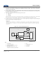
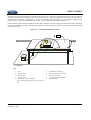
When performing testing using either the biconical or log antenna, the coaxial cable shall be routed directly behind the
antenna as illustrated in Figure 7-1. The cable shall remain parallel to the test chamber floor for a minimum of 1000
mm behind the rear most element of the antenna (see Figure 7-1). The cable shall include ferrite beads (Fair-Rite
Type 43 or equivalent) with a maximum spacing of 150 mm. Ferrite beads are not required for sections of the antenna
cable lying on the test chamber floor. The purpose for this modification is to minimize cable affects on the antenna's
published antenna correction factors.
•
If a pre-amplifier is used to meet the ambient requirements (see section 7.3) , the device should be located where the
antenna cable meets the test chamber floor (see Figure 7-1). Location of the pre-amplifier at the antenna connector is
not recommended due to possible interactions between the antenna elements and the power supply wiring to the
preamplifier. The preamplifier may be located outside of the test chamber as long as the measurement system ambient
requirements are met. See section 7.2.2 for additional requirements when using preamplifiers.
•
When tests are performed above 1000 MHz, the receiving antenna shall be relocated such that its center is aligned with
the center of the DUT as illustrated in Figure 15 of CISPR 25. Height of the antenna relative to the ground plane
bench shall remain unchanged.
•
The DUT and any electronic hardware in the Load Simulator shall be powered from an automotive battery (see
paragraph 4.5.4 for requirements). The battery negative terminal shall be connected to the ground plane bench. The
battery may be located on, or under the test bench. The standard test setup shown in Annex G shall be used for the
Load Simulator, battery and Artificial Networks.
•
The total harness length shall be 1700 mm (+300 /-0 mm). The harness shall lie on an insulated support 50 mm above
the ground plane.
•
The DUT shall be placed on an insulated support 50 mm above the ground plane. However, if the outer case of the
DUT is metal and, when installed in the vehicle is electrically connected to the vehicle's sheet metal, the DUT shall be
mounted and electrically connected to the ground plane during the test in a manner representative of the vehicle
application. This configuration is only permitted if documented in the product engineering specification and is
representative of the vehicle application. The DUT grounding configuration shall be documented in the EMC test
plan and test report.
•
For some DUT's, deviations from the standard test setup may be necessary to facilitate testing. These deviations must
be reviewed and approved by the FMC EMC department prior to commencement of testing. Test setup deviations
shall be documented in the EMC test plan and test report.
7.2.1
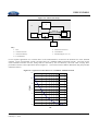
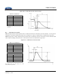
Test Setup for Engine Control Circuits (Bands EU1, G1 only)
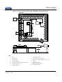
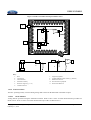
When testing engine control electronics that are packaged in the engine compartment, the test setup illustrated in Figure 7-2
may be used. This test setup shall not be used for any other module or subsystem.
The ignition and injector wires shall be removed from the main wire harness and located directly on the ground plane 100
mm behind the main wire harness. RF shielding, as illustrated in Figure 7-2 shall be placed over the selected wiring. The RF
shielding shall be electrically connected to the ground plane via direct connection (e.g. screws) or copper tape with
conductive adhesive. Use of this test setup shall be documented in the EMC test plan and approved by the FMC EMC
department prior to commencement of testing. Photos of the test setup shall be included in the test report.
© Copyright Ford Motor Company – All Rights Reserved
February 11, 2010
Page 17 of 121
EMC-CS-2009.1
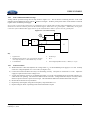
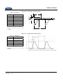
Figure 7-1: RE 310 Test Antenna Cable Configuration (excludes Rod antenna)
≥ 1000
≥ 1000
1
≤ 150
1
≤ 150
2
2
3
3
Log Antenna
Biconical Antenna
Scale: millimeters
Key:
1.
Ferrite Cable Bead
(Fair-Rite Type 43 or equivalent)
2.
Preamplifier (if required)
3.
Floor of ALSE
Figure 7-2: RE 310 Test Setup (EU1, G1) DUTs with Selected Wiring in Engine Compartment
100
1
2
100
9
6
8
6
7
8
7
2
9
9
5
5
−
+
3
4
> 100
8
Key
1.
DUT
6.
Ground Plane Bench
2.
Insulated Support (εr≤ 1.4)
7.
Cable Harness (1700 -0/+300 mm)
3.
Load Simulator
8.
Selected Wiring Removed from Cable Harness
9.
RF Shield placed over Selected Wiring Removed from
Cable Harness (may use aluminum foil)
4.
Automotive Battery
5.
Artificial Network
© Copyright Ford Motor Company – All Rights Reserved
February 11, 2010
Page 18 of 121
EMC-CS-2009.1
Rod Antenna Not Shown. Physical Dimensions conform to CISPR 25 3rd Edition Except where noted. Dimensions shown are in millimeters.
7.2.2
Measurement System Requirements
The measurement receiver (spectrum analyzer or stepped receiver) shall be compliant to CISPR 16-1-1 as specified in section
4.4 of CISPR 25 3rd edition. Measurement receivers using Fast Fourier Transform (FFT) techniques may be used with prior
approval from the FMC EMC department (approval will be linked to laboratory recognition) . A list of approved
measurement systems may be found at: www.fordemc.com.
Tables 7-3, 7-4 and 7-5 list the measurement system requirements when using either a swept (i.e. spectrum analyzer) or
stepped EMI receiver.
•
For all bands except, M1, M2, M3, Limit A is based on use of a 9/10 kHz measurement bandwidth combined with
either Peak or Average detection. Limit B is based on use of 120 kHz measurement bandwidth combined with QuasiPeak detection.
•
For bands EU1 and G1, Limit A is based on use of a 0.2 – 1 kHz measurement bandwidth combined with Average
detection. Limit B is based on use of 9 kHz measurement bandwidth combined with Quasi Peak detection.
•
For bands M1, M2 and M3, Limit A is based on use Average detection with 120 kHz measurement bandwidth. Limit
B is based on use Quasi Peak detection with 120 kHz measurement bandwidth.
•
Measurement dwell times listed in Tables 7-3, 7-4 and 7-5 may be increased if the DUT operates with intermittent
duration, however specific rational must be documented in the EMC test plan to justify the increase.
Above 30 MHz, a low noise preamplifier is often required to meet the measurement system ambient requirements. However,
use of a preamplifier will increase the potential of overload usually from out of band signals. To minimize this potential, it is
recommended that the net gain of the pre-amplifier be selected to just meet the ambient requirements specified in section 7.3,
step a). The laboratory shall also establish a procedure to avoid overload of the preamplifier, such as using a step attenuator.
Table 7-3: RE 310 Measurement System Setup Requirements (Bands EU1, G1)
Swept Receivers
Limit A
Limit B
Limit A
Limit B
Average
Quasi-Peak
Average
Quasi-Peak
0.2 ≤ MBW ≤ 1
9/10 (1)
0.2 ≤ MBW ≤ 1
9
≥ 3*MBW
n/a
0.5*MBW
4.5
0.02
1
Detection Method
Measurement Bandwidth
(kHz)
{MBW}
Video Bandwidth (kHz)
Frequency sweep rate
(sec/kHz) (2)
Frequency Step Size (kHz) (2)
Measurement Time per Frequency
Step (sec ) (3)
1.
2.
3.
Stepped Receivers
≥ 0.03
MBW
≥ 0.2
Any bandwidth in this range may be used.
Sweep rate calculated from MBW given in kHz.
Sweep rate and measurement time may be increased for low repetition rate signals. See section 7.2.2 for details
© Copyright Ford Motor Company – All Rights Reserved
February 11, 2010
Page 19 of 121
EMC-CS-2009.1
Table 7-4: RE 310 Measurement System Setup Requirements (All Bands except M1, M2, M3, EU1, G1)
Swept Receivers
Detection Method
Measurement Bandwidth
(kHz)
Stepped Receivers
Limit A
Limit B
Limit A
Limit B
Peak or Average
Quasi-Peak
Peak or Average
Quasi-Peak
9/10 (2)
120
9/10 (2)
120
≥ 3*MBW
n/a
≥ 0.003
≥ 0.001
0.5*MBW
60
0.005
1
{MBW}
Video bandwidth (kHz)
Frequency sweep rate
(sec/kHz)
Frequency Step Size (kHz)
Measurement Time per Frequency
Step (sec ) (2)
1.
To allow the use of various receiver types, either bandwidth may be used
2.
Sweep rate and measurement time may be increased for low repetition rate signals. See section 7.2.2 for details
Table 7-5: RE 310 Measurement System Setup Requirements (Bands M1, M2, M3)
Swept Receivers
Detection Method
Measurement Bandwidth {MBW}(1)
(kHz)
Video bandwidth (kHz)
Frequency sweep rate
(sec/kHz)
Frequency Step Size (kHz)
Measurement Time per Frequency
Step (sec ) (1)
1.
Stepped Receivers
Limit A
Limit B
Limit A
Limit B
Average
Quasi-Peak
Average
Quasi-Peak
120
120
120
120
≥ 500
n/a
≥ 0.003
≥ 0.001
60
60
0.005
1
Sweep rate and measurement time may be increased for low repetition rate signals. See section 7.2.2 for details
© Copyright Ford Motor Company – All Rights Reserved
February 11, 2010
Page 20 of 121
EMC-CS-2009.1
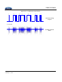
7.3
Test Procedure
a) Prior to measurement of DUT radiated emissions, test setup ambient levels (i.e. all equipment energized except DUT)
shall be verified to be 6 db or more below the specified requirements listed in Table 7-2. If this requirement is not
met, testing shall not proceed until the associated test setup issues are resolved. Plots of the test setup ambient shall be
included in the test report. Test setup ambient measurements shall be performed using a 9/10 kHz MBW with peak
detection except for bands EU1, G1, and G8, which require use of average detection. All test setup ambient
measurements shall be performed using only vertical polarization of the measurement antenna.
b) Measurement of DUT radiated emissions shall be performed over all frequency bands listed in Tables 7-1 and 7-2. At
measurement frequencies ≥ 30 MHz, measurements shall be performed in both vertical and horizontal antenna
polarizations.
c) When assessing DUT performance per Level 1 and Level 2 above 30 MHz (except band G8), measurements may be
initially performed using 120 kHz MBW with peak detection along with the measurement system requirements
delineated in Table 7-5 (Limit A). This approach facilitates reduction in the overall measurement time. If the resulting
DUT emission levels are below Limit A (Level 1 and Level 2(Peak)), the test data may be submitted as the final result.
When using 120 kHz MBW with PK detection to assess DUT emissions per Level 2, Limit A (Peak), measurement
system ambient requirements as delineated in step a) may be waived.
If DUT emission levels, measured in step c), are above any of the individual band requirements, additional
measurements shall be performed using the measurement system requirements listed in Tables 7-4 and 7-5. This
process is illustrated in Figures 7-3 and 7-4. Contact the FMC EMC department regarding questions and/or
clarifications with respect to this process.
When assessing compliance to Level 2, Limit A, Peak or Average measurements shall be performed over the
entire frequency band(s), where the emissions from step c) exceeded the limit. Separate measurements to
demonstrate compliance to both PK and AVG limits is not required.
When assessing compliance to Level 2, Limit B, measurements are limited to individual frequencies where the
emissions from step c) exceeded the limit.
d) Tests shall be repeated for all DUT operating modes delineated in the component EMC test plan.
© Copyright Ford Motor Company – All Rights Reserved
February 11, 2010
Page 21 of 121
EMC-CS-2009.1
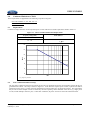
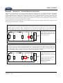
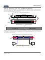
Figure 7-3: Recommended Process for Assessing DUT Emissions per RE 310 Level 1 Requirements
Measure DUT Emissions from 30-1000 and
1447 -1494 MHz using 120 kHz MBW, PK+
detection and measurement system
requirements listed in Table 7-5.
Step 1
Level 2
Evaluation
See Figure 7-4
Are all PK emissions
below Level 1, Limit A
per Table 7-1?
N
Limit A
Step 2
Re-measure DUT emissions at all
non-compliant frequencies in
accordance with Table 7-5 for Limit A+.
Are DUT emissions
below Level 1, Limit A
per Table 7-1?
Y
DUT
Compliant to
Limit A
© Copyright Ford Motor Company – All Rights Reserved
February 11, 2010
N
DUT
Non-Compliant
DUT is compliant to
Level 1, Limit A and B
requirements.
Y
Limit B
Re-measure DUT emissions at all
non-compliant frequencies in
accordance with Table 7-5 for Limit B.
N
Are DUT emissions
below Level 1, Limit B
per Table 7-1?
Y
DUT
Compliant to
Limit B
Page 22 of 121
EMC-CS-2009.1
Figure 7-4: Recommended Process for Assessing DUT Emissions to RE310 Level 2 Requirements
(Excludes bands EU1, G1, G8)
Measure DUT Emissions from 30-1000 and
1447 -1494 MHz using 120 kHz MBW, PK+
detection and measurement system
requirements listed in Table 7-5.
Step 1
Level 1
Evaluation
See Figure 7-3
Are all PK emissions
below Level 2, Limit A (PK)
per Table 7-2?
N
Limit A
Step 2
Re-measure DUT non-compliant
emissions in accordance with Table
7-4 for Limit A. Measurements shall
be made over entire frequency
band(s) where non-compliance was
noted in Step 1+.
Are DUT emissions
below Level 2, Limit A
per Table 7-2? **
Y
DUT
Compliant to
Limit A
N
DUT is compliant to
Level 2, Limit A and B
requirements.*
Y
Limit B
Re-measure DUT non-compliant
emissions in accordance with Table
7-4 for Limit B. Measurements shall
be made at all frequencies where
non-compliance was noted in Step 1.
DUT
Non-Compliant
N
Are DUT emissions
below Level 2, Limit B
per Table 7-2? **
Y
DUT
Compliant to
Limit B
+
Simultaneous PK and AVG measurements may be made using RF receivers with dual detector capability
*
Ambient requirements (6dB) do not apply when using 120 kHz MBW, PK detection to verify Level 2, Limit A
requirements.
Measurement system and test setup ambient requirements (6dB) apply when using 9/10kHz MBW to verify Level 2, Limit
A requirements.
**
© Copyright Ford Motor Company – All Rights Reserved
February 11, 2010
Page 23 of 121
EMC-CS-2009.1
8.0
Conducted RF Emissions: CE 420
These requirements are applicable to the following component categories:
Electronic Modules: A, AS, AM
Shall meet Average Limits only.
Electronic Modules: AX, AY
Shall meet both Average and Quasi Peak Limits.
Electric Motors: EM
Shall meet both Average and Quasi Peak Limits.
Electronic Motors: BM
Shall meet Quasi Peak Limits only
These requirements are not applicable for electric motors/actuators that operate with intermittent duration AND with direct
operator control via depression of a switch unless packaging requirements place the motor and/or it's wiring within 500mm of
the vehicle's radio antenna. The FMC EMC department shall review and approve application of these requirements to these
devices prior to commencement of testing.
These requirements may be relaxed or waived for components having a shielded power and power return wiring system
implemented with shielded cable or by placement of multiple components in a common shielded enclosure. However this
requires prior approval by the FMC EMC department upon their review of testing and/or analysis demonstrating that the "invehicle" packaging will not introduce alternate paths for coupling of conducted emissions exceeding CE420 levels on to
unshielded power and return circuits.
8.1
Requirement
Conducted RF voltage emissions on the component power and power return circuits shall not exceed the requirements listed
in Table 8-1. Requirements are limited to Long Wave (LW), Medium Wave (i.e. AM) and FM broadcast services.
Table 8-1: CE 420 Conducted Emissions Requirements
Band
#
RF Service
EU1
Limits
Frequency Range
(MHz)
Average (dbuV)
Quasi-Peak (dbuV)
Long Wave (LW)
0.15 - 0.28
77
89
G1
Medium Wave (AM)
0.53 - 1.7
54
66
JA1
FM 1
76 -90
36
G3
FM 2
87.5 - 108
36
© Copyright Ford Motor Company – All Rights Reserved
February 11, 2010
Page 24 of 121
EMC-CS-2009.1
8.2
Test Verification and Test Setup
The requirements of CISPR 25 (Edition 3), voltage method shall be used for verification of the component performance
except where noted in this specification. If the DUT has separate power/power return circuits, separate tests shall be
performed on each circuit. Circuits not being tested shall be connected directly to an automotive battery. This requirement
may be waived if the multiple circuits are used only meet the operating current demands of the DUT (e.g. single power
circuit, but with multiple connector pins). Under these conditions, the all power circuits are tied to the Artificial Network.
•
Electronic hardware in the Load Simulator shall be powered from an automotive battery (see paragraph 4.5.4 for
requirements). The battery negative terminal shall be connected to the ground plane.
•
The power/power return wiring between the DUT and the Artificial Network shall be 200 +/-50 mm in length.
•
The DUT shall be placed on an insulated support 50 mm above the ground plane. However, if the outer case of the
DUT is metal and, when installed in the vehicle is electrically connected to the vehicle's sheet metal, the DUT shall be
mounted and electrically connected to the ground plane during the test in a manner representative of the vehicle
application. This configuration is only permitted if documented in the product engineering specification and is
representative of the vehicle application. The DUT grounding configuration shall be documented in the EMC test
plan and test report.
•
If the DUT’s power return is required to be locally grounded in the vehicle within 200 mm of the DUT (must be
specified in the DUT engineering specification), the DUT power return shall be connected directly to the ground plane.
Under these conditions, the Artificial Network connected to the DUT’s power return may be omitted.
8.2.1
Measurement System Requirements
The measurement receiver (spectrum analyzer or stepped receiver) shall be compliant to CISPR 16-1-1 as specified in section
4.4 of CISPR 25 3rd edition. Measurement receivers using Fast Fourier Transform (FFT) techniques may be used with prior
approval from the FMC EMC department. A list of approved measurement systems may be found at: www.fordemc.com.
Tables 7-3 and 7-4 in section 7.2.2 list the measurement system requirements when using either a swept (i.e. spectrum
analyzer) or stepped EMI receiver. Measurement system requirements are identical to those respective bands for RE 310.
.For Bands EU1 and G1, it is recommended that the measurement time (stepped receivers) be equal to 1/f, where f is the
signal repletion rate. Swept receivers need to be adjusted accordingly. Measurement times used shall be documented in the
EMC test plan.
8.3
Test Procedure
a)
Prior to measurement of DUT conducted emissions, test setup ambient levels (i.e. all equipment energized except
DUT) shall be verified to be 6 db or more below the specified requirements listed in Table 8-1. Test setup ambient
levels shall be at least 6dB below the specified limits otherwise testing shall not proceed until the associated test setup
issues are resolved.
b) Measurement of DUT conducted emissions shall be performed over each frequency band listed in Table 8-1.
c) Tests shall be repeated for all DUT operating mode(s) delineated in the component EMC test plan.
d) When assessing DUT performance to Quasi-Peak limits, the use of peak detection with the same measurement
bandwidth is permitted as a quick pre-screen to increase testing efficiency. If the peak emissions are below the limit,
the test data may be submitted as the final result. If the peak emissions exceed the band requirements, it will be
necessary to re-sweep individual frequencies where the limit was exceeded using Quasi-peak detection. Peak and
quasi-peak data shall be submitted in the test report.
© Copyright Ford Motor Company – All Rights Reserved
February 11, 2010
Page 25 of 121
EMC-CS-2009.1
9.0
Conducted Emissions: CE 421
These requirements are applicable to the following component categories:
Electronic Modules: A, AS, AM, AX, AY
Electric Motors: EM
9.1
Requirement
Conducted voltage emissions on all component power circuits shall not exceed the requirements listed in Table 9-1.
Figure 9-1: CE 421 Conducted Emissions Requirements
Frequency Range (kHz)
Limits (dBuV)*
10 - 20
111
20 - 150
111 − 40 Log ⎛⎜ f ⎞⎟
⎝ 20 ⎠
120
110
dBuV
100
90
80
70
60
10
100
150
kHz
* f= frequency in kHz
9.2
Test Verification and Test Setup
The test setup is identical to that used for CE 420 except only one Artificial Network is used regardless of how the DUT is
grounded in the vehicle. The setup is shown in Figure 9-1. If the DUT has separate power circuits, separate tests shall be
performed on each circuit. Circuits not being tested shall be connected directly to an automotive battery. This requirement
may be waived if the multiple circuits are used only meet the operating current demands of the DUT (e.g. single power
circuit, but with multiple connector pins). Under these conditions, all power circuits are tied to the artificial network.
© Copyright Ford Motor Company – All Rights Reserved
February 11, 2010
Page 26 of 121
EMC-CS-2009.1
Figure 9-2: CE 421 Test Setup
4
6
200 ± 50
3
+
_
1
2
7
5
Key:
1.
2.
3.
4.
5. Measurement Receiver
6. Ground Plane
7. Insulated Support (εr≤ 1.4)
DUT
Artificial Network
Automotive Battery
Load Simulator
CE 421 requires application of a correction factor to the measured data to account for the insertion loss of the Artificial
Network. Figure 9-2 illustrates 'typical' correction factor for a standard CISPR 25 artificial network. Correction for the
actual Artificial Networks used for testing shall be measured by the test laboratory and used when verifying DUT
performance relative to the requirements shown in Figure 9-1. The correction factor shall be determined using the procedure
outlined in Annex I.
Figure 9-3: Typical Correction Factor for a CISPR 25 Artificial Network
12
10
CF (dB)
8
6
4
2
0
10K
100K
150K 200K
Hz
© Copyright Ford Motor Company – All Rights Reserved
February 11, 2010
Page 27 of 121
EMC-CS-2009.1
9.2.1
Measurement System Requirements
The measurement receiver (spectrum analyzer or stepped receiver) shall be compliant to CISPR 16-1-1 as specified in section
4.4 of CISPR 25 3rd edition. Measurement receivers using Fast Fourier Transform (FFT) techniques may be used with prior
approval from the FMC EMC department. A list of approved measurement systems may be found at: www.fordemc.com.
Table 9-2 lists the measurement system requirements when using either a swept (i.e. spectrum analyzer) or stepped EMI
receiver.
Table 9-1: CE 421 Measurement System Setup Requirements
Swept Receivers
Stepped Receivers
Average
Average
0.2 ≤ MBW ≤ 1
0.2 ≤ MBW ≤ 1
Detection Method
Measurement Bandwidth {MBW}(1) (kHz)
0.1
Video Bandwidth (kHz)
Frequency sweep rate
≥ 0.03
(sec/kHz) (2)
MBW
0.5*MBW
Frequency Step Size (kHz)
Dwell Time per Frequency Step (sec )
1
2
9.3
≥ 0.02
Any bandwidth in this range may be used.
Sweep rate is calculated from MBW given in kHz.
Test Procedure
The correction factor for the Artificial Network shall be applied to all measured data (i.e. test setup ambient, DUT
conducted emissions) prior to verification the limits shown in Figure 9-1 using the equation below:
VCE ( f ) = Vraw ( f ) + CF ( f )
Where:
VCE (f) = DUT Conducted emissions (dBuV) at specific measurement frequency. VCE(f) is compared to the
limits shown in Table 9-1
VRAW (f) = Conducted emissions (dBuV) from measurement port on Artificial Network at specific
measurement frequency
CF= Correction factor (dB) for Artificial Network at specific measurement frequency
a)
Prior to measurement of DUT conducted emissions, test setup ambient levels (i.e. all equipment energized except
DUT) shall be verified to be 6 db or more below the specified requirements listed in Figure 9-1. If ambient levels are
less than 6 db below the specified limits, testing shall not proceed until the associated test setup issues are resolved.
Plots of the test setup ambient shall be included in the test report.
b) Measurement of the DUT's power line conducted emissions shall be performed over frequency range listed in Table 91.
c) Tests shall be repeated for all DUT operating mode(s) delineated in the component EMC test plan.
© Copyright Ford Motor Company – All Rights Reserved
February 11, 2010
Page 28 of 121
EMC-CS-2009.1
10.0
Conducted Transient Emissions: CE 410
These requirements are applicable to the following component categories:
Electronic Modules: AX, AY
Electric Motors and Inductive Devices: BM, EM, R
10.1
Requirement
The component shall not produce transient voltages magnitudes exceeding +75 / - 100 volts on its power supply circuit(s).
10.2
Test Verification and Test Setup
The DUT shall be tested in accordance with ISO 7637-2, except where noted in this specification, using the test setup
illustrated in Figure 10-1.
•
The DUT power circuit(s) shall be connected directly to the Artificial Network through either mechanical or
electromechanical switch with a single set of contacts. The switch shall have the following characteristics:
-
contact rating: I ≥ 30 A or twice the rated current of the DUT (which ever is greater), continuous, resistive
load
no suppression across relay contact;
single/double position contact electrically insulated from the coil circuit
Coil with transient suppression (applies only to electromechanical relay)
The actual switch used for testing shall be specified in the EMC test report.
•
The wiring between the DUT and the Artificial Network shall be 200 +/-50 mm in length. No other connections shall
be made between the switch and the DUT.
•
The supply voltage to the DUT shall be +15 -0.5/+0 volts. The power supply shall have a short circuit current
capability 100 amperes or twice the specified stall current of the DUT. The negative terminal of the power supply
shall be connected to the ground plane.
•
A digital sampling scope shall be used for the voltage measurements using a capable sampling rate of 1 Giga-samples
per second (single acquisition capability) and a minimum memory depth of 2048 samples. The bandwidth shall be
greater than 100 MHz. The voltage shall be measured using a 1:100 probe (< 4 pf). See ISO 7637-2 for additional
requirements
•
The DUT shall be placed on an insulated support 50mm above the ground plane. A DUT with an outer metal chassis
may be electrically connected to the ground plane only if the DUT's design requires that its chassis must be grounded
to the vehicle for functionality (the DUT engineering specification must state this requirement). The DUT's grounding
configuration shall be documented in the EMC test plan and test report.
•
If the DUT is an electric motor or actuator, it shall be tested in the “stall” condition unless analysis demonstrates this
condition can not occur. If the motor contains internal protection (e.g. PTC device) that would limit or interrupt
current to the DUT during a stall condition, testing shall be performed with the maximum rated mechanical load on the
motor/actuator.
10.3
a)
b)
c)
d)
e)
f)
Test Procedures
Close the external switch contacts (see Figure 9-1) and power up the DUT. Verify the DUT is functioning properly.
Set the oscilloscope time base to 1 msec/div.
Set the oscilloscope for single acquisition mode ("single shot"). Set the trigger level to +10 volts.
Open and close the external switch contacts to verify the scope properly triggers. Do not proceed until triggering has
been verified!
Repeat steps a) through c) except the trigger level of the digital sampling scope shall be set to +80 volts .
Adjust the oscilloscope sampling rate to the highest level available for the time base selected.
© Copyright Ford Motor Company – All Rights Reserved
February 11, 2010
Page 29 of 121
EMC-CS-2009.1
g) If the DUT is of component categories AX, AY and EM, measure and record the peak transient voltages while
exercising the DUT functions in operating modes identified in the EMC test plan. This step may be omitted for
component categories BM and R.
h) For all component categories with switched power circuits, measure and record peak positive transient voltages
exceeding the trigger level while by turning the DUT off and on ten times (10 measurements for each condition) via
the external switch shown in Figure 10-1.
i) Repeat step e) through h) for each of the following time base values:
j)
•
100 usec/div;
•
1 usec/div
• 0.5 usec/div
Alternative time base values may be selected if those listed are not available for the oscilloscope used. The lab shall
use the closest time base value available. The time bases used shall be documented in the EMC test report.
Re-adjust the trigger level of the digital sampling scope to -60 volts. Repeat steps e) through i) except record the peak
negative transient voltages exceeding the trigger level.
Design Note
Although CI 410 requirements are validated at room temperature, the product should be designed to meet the
same requirements at -45 degrees C or the coldest ambient temperature specified in the product's engineering
specification
Figure 10-1: CE 410 Transient Emissions Test
4
9
100 +/- 25
5
7
+
1
3
2
-
200 +/- 50
6
8
All Dimensions in mm
Key:
1. Power Supply
2. Artificial Network (AN)
3. Mechanical /Electromechanical Switch
4. Digitizing Oscilloscope
5. High Impedance Probe (1:100, C < 4pf.
See ISO 7637-2) Example: Agilent 10076A
© Copyright Ford Motor Company – All Rights Reserved
February 11, 2010
6. DUT
7. Insulated support (εr≤ 1.4)
8. Load Simulator
9. Ground Plane
Page 30 of 121
EMC-CS-2009.1
11.0
RF Immunity: RI 112, RI 114, RI 115
Radiated immunity requirements cover the frequency range from 1 to 3100 MHz. Requirements are based on anticipated
“off-vehicle” and “on-vehicle” RF sources (e.g. amateur radio, cellular phones). These requirements are applicable to the
following component categories:
Electronic Modules: A, AS, AM, AX, AY, AW (excludes RI 112)
Electronic Motors: EM
RF immunity to hand portable transmitters (RI 115), applicability is limited to selected devices packaged inside the passenger
or luggage compartments. See section 11.5 for details.
11.1
Generic Requirements
Component functional performance shall meet the acceptance criteria delineated in Table 11-1. Due to the wide frequency
coverage, multiple test methods are needed for performance verification. Level 1 and Level 2 requirements are dependent on
those test methods.
Table 11-1: RF Immunity Acceptance Criteria
Requirement
Level
Functional Performance Status
Class A
1
2
1
2
I
II
Class B
Class C
(1)
I
I
(1,2)
II
I
For audio, video and RF functions, some degradation in performance (e.g. distortion) is permitted,
but shall be defined and quantified in the component/subsystem's engineering specification and EMC
Test Plan.
For audio components, volume level (measured at speaker terminals) shall not increase by more than
50%.
3
11.2
Generic Test Setup and Test Procedures
•
The DUT wire harness shall be 1700 mm (+ 300/- 0 mm) long. The harness shall be routed 50 mm above the ground
plane (excludes RI 114 bands 6 and 7) on an insulated support (εr ≤ 1.4) over the entire length between the DUT and
the Load Simulator. The harness can also be used for CISPR 25 Radiated Emission testing.
•
When performing testing per RI 112 and RI 114 (ALSE, Bands 4 and 5), the DUT shall be placed on an insulated
support 50 mm above the ground plane. However, if the outer case of the DUT is metal and, when installed in the
vehicle is electrically connected to the vehicle's sheet metal, the DUT shall be mounted and electrically connected to
the ground plane during the test in a manner representative of the vehicle application. This configuration is only
permitted if documented in the product engineering specification and is representative of the vehicle application. The
DUT grounding configuration shall be documented in the EMC test plan and test report.
•
When performing testing per RI114, Reverberation or ALSE, (Bands 6 and 7), a braided copper ground strap
shall be used to connect the DUT case to the battery negative terminal. The strap shall be 1700 mm (+300/- 0
mm) with a width no greater than 13 mm. The strap shall be co-routed with the test harness. This method
shall also be used if the DUT power returns require local grounding.
•
When performing testing per RI 112 and RI 114, forward power shall be used as reference parameter for stress level
characterization and during the actual test of the DUT. When performing testing per RI 115, net forward shall be used
as reference parameter.
•
When using pulse modulations, either peak envelope power (PEP) sensors or a spectrum analyzer are required to
measure forward power however use of PEP sensors are preferred. If the spectrum analyzer is used, it shall be tuned
to each individual frequency using zero span setting with a measurement bandwidth greater than or equal to 3 MHz
(for both the resolution or IF bandwidth and the video bandwidth, if applicable). The same type of measurement
device shall be used during both calibration and test. Alternative methods are not permitted.
© Copyright Ford Motor Company – All Rights Reserved
February 11, 2010
Page 31 of 121
EMC-CS-2009.1
11.3
Generic Test Procedures
•
RF Immunity testing shall be performed with linear frequency step sizes no greater than those listed in Table 11-2.
•
Peak conservation shall be used per ISO 11452-1. CW and modulation (AM & Pulsed) dwell times shall be a
minimum of 2 seconds. Longer dwell times may be necessary if DUT function response times are expected to be
longer. This information shall be documented in the EMC test plan.
•
Amplifier output harmonics content shall conform to the requirements of ISO 11452-1 (2005). Field modulation and
leveling shall conform to the requirements delineated in Annex B.
•
The AM modulation frequency shall be 1 kHz at a level of 80%.
•
Testing shall be initially performed using Level 2 requirements. If deviations are observed, the stress level shall be
reduced until the DUT functions normally. The stress level shall then be increased until the deviation occurs. The
stress level at this point shall be verified to meet the performance requirements delineated in Table 11-1. If the
performance requirements are not met, the stress level shall be reported as the deviation threshold.
Table 11-2: RF Immunity Test Frequency Steps
Frequency Range
(MHz)
Frequency Step Size
1 - 30
0.5
30 - 200
2
200 - 400
5
400 - 1000
10
1000 - 3100
20
© Copyright Ford Motor Company – All Rights Reserved
February 11, 2010
(MHz)
Page 32 of 121
EMC-CS-2009.1
11.4
Requirements 1 -400 MHz: RI 112
The device shall operate as specified in Table 11-1 when exposed to the RF current levels and modulation listed and
illustrated in Figure 11-1. The currents are produced using the BCI test method.
RI 112 can not be used for component category AW (no wire harness). Alternative methods may be used (e.g. TEM cell), but
only with prior authorization by the FMC EMC department. The test method used, including test setup detail shall be
documented in the EMC test plan.
Figure 11-1: RI 112 Requirements using Bulk Current Injection (BCI)
Frequency Range
Level 1
Level 2
(MHz)
(dBµA)
(dBµA)
1
1 - 15
64 - 100
70 – 106
CW, AM 80%
2
15 - 30
100
106
CW, AM 80%
3
30 – 400
100 - 90
106 - 96
CW, AM 80%
Band
Modulation
120
Level 2 (dBuA) = 70 + 30.61*log(f)
Level 1 (dBuA) = 64 + 30.61*log(f)
Calibration Current (dBuA)
110
Level 2 (dBuA) =106 – 8.89*log(f/30)
Level 1 (dBuA) = 100 – 8.89*log(f/30)
100
Level 2 (dBuA) = 106
Level 1 (dBuA) = 100
90
80
70
f = Frequency in MHz)
60
1
10
100
1000
MHz
© Copyright Ford Motor Company – All Rights Reserved
February 11, 2010
Page 33 of 121
EMC-CS-2009.1
11.4.1 Test Verification and Test Setup
Verification of component performance shall be in accordance with the BCI (substitution method) per (ISO 11452-4) except
where delineated in this specification.
•
The DUT shall be powered from an automotive battery (see paragraph 4.5.4 for requirements). The battery negative
terminal shall be connected to the ground plane. The battery may be located on, or under the test bench. The standard
test Setup shown in Annex G shall be used for the Load Simulator, battery and Artificial Networks.
•
The test bench shall include a sufficiently large ground plane, such that the test harness lies in a straight line. Spacing
between the edge of the ground plane and the test harness, DUT, Load Simulator etc shall conform to ISO 11452-4.
•
The distance between the test Setup and all other conductive structures (such as the walls of the shielded enclosure)
with the exception of the ground plane shall be ≥ 500 mm.
•
In the frequency range from 1 MHz - 30 MHz all power return (i.e. ground) wires of the DUT wiring harness shall be
terminated directly to the ground plane (DBCI) as illustrated in Figure 11-2a. The length of the wiring shall be 200 ±
50 mm. No power return wiring shall be routed around the BCI injection probe. These requirements may be waived
if the power and power return wiring are twisted (must be specified in the product engineering specification) but must
be documented in the EMC test plan.
•
In the frequency range 30 MHz.- 400 MHz all wires of the DUT wiring harness shall be routed inside of the injection
probe (CBCI) as illustrated in Figure 11-2b.
•
If the DUT has multiple connectors, testing shall be repeated (1 – 400 MHz) with the injection probe placed around
the individual harness associated with each individual DUT connector. Circuits contained in each harness shall be
documented in the EMC test plan.
•
The injection probe shall be insulated from the ground plane.
•
An optional current monitoring probe may be used, but if used, it shall be placed 50 mm from the DUT. The monitor
probe shall be insulated from the ground plane.
11.4.2 Test Procedure
Use the calibrated injection probe method (substitution method) according to ISO 11452-4.
a) Use step frequencies listed in Table 11-2 and the modulation as specified in Figure 11-1.
b) In the frequency range from 1 to 30 MHz, testing shall be performed at two fixed injection probe positions (150 mm,
450 mm).
c) In the frequency range from 30 MHz to 400 MHz, testing shall be performed at two fixed injection probe positions
(450 mm, 750 mm).
d) If deviations are observed, the induced current shall be reduced until the DUT functions normally. Then the induced
current shall be increased until the deviation occurs. This level shall be reported as the deviation threshold.
e) Repeat testing for each harness connected to the DUT.
f) The DUT operating mode(s) exercised during testing shall conform to that delineated in the EMC test plan.
g) If a monitor probe is used during testing, it shall not be used to adjust the RF current delineated in Figure 11-1. The
measured values are used for information only and may be included in the test report.
© Copyright Ford Motor Company – All Rights Reserved
February 11, 2010
Page 34 of 121
EMC-CS-2009.1
Figure 11-2: RI 112 DUT Harness Configurations
_4 +
3
_4 +
1700 -0/+300
d
3
3
1700 -0/+300
d
3
10a
11
9
NC
2
1
9
2
12
12
Ground Plane
11
10b
1
12
12
Ground Plane
6
5
7
6
5
8
7
(a) DBCI
8
(b) CBCI
Key:
1.
DUT
8.
Current Monitoring Equipment (OPTIONAL)
2.
Load Simulator
9.
DUT Wire harness
3.
Artificial Network
10a. DUT Power Return removed from wire harness and connected
directly to sheet metal. Wire length is 200 ±50 mm.
4.
Automotive Battery
10b. DUT Power Return included in DUT wire harness
5.
Injection Probe
11. DUT Case Ground (see section 11.3.1)
6.
Monitor Probe (OPTIONAL)
12. Insulated Support (εr≤ 1.4)
7.
RF Generation Equipment
© Copyright Ford Motor Company – All Rights Reserved
February 11, 2010
d = Injection probe distance from DUT (see section 11.4.2)
Page 35 of 121
EMC-CS-2009.1
11.5
Requirements: 400 – 3100 MHz: RI 114
The device shall operate as specified in Table 11-1 when exposed to RF electromagnetic fields as delineated in Table 11-3.
Table 11-3: RI 114 Requirements ( 400 – 3100 MHz )
Band
Frequency Range
(MHz)
Level 1
(V/m)
Level 2
(V/m)
4
400 - 800
50
100
5
800 - 2000
50
70
6
1200 - 1400
n/a
7
2700 – 3100
n/a
Modulation
CW, AM 80%
Pulsed PRR= 18 Hz, PD= 28 msec (1)
CW, Pulsed PRR= 217 Hz, PD=0.57 msec
300
600 (2)
300
Pulsed PRR= 300 Hz, PD = 3 usec, (3)
with only 50 pulses output every 1 sec.
(1,2)
600 (2)
1.
Pulse Modulation limited to 400 – 470 MHz
2.
600 V/m requirements are only applicable to selected components associated with supplemental restraints
system including frontal crash sensors. Contact FMC EMC department for specific applicability
3.
Pulse duration (PD) shall be extended to 6 usec when testing using the reverberation (mode tuned) method.
See 11.4.2.2 for additional detail.
11.5.1 Test Verification and Test Setup
Verification of device performance shall be in accordance with either the following methods:
•
ALSE Method (ISO 11452-2) except where noted in this specification. The tests is similar to that used for radiated
emissions testing (see section 7.2).
•
Reverberation, (Mode Tuned) Method (IEC 61000-4-21) except where noted in this specification.
11.5.1.1 ALSE Method (Bands 4 and 5)
•
The DUT and any electronic hardware in the Load Simulator shall be powered from an automotive battery (see
paragraph 4.5.4 for requirements). The battery negative terminal shall be connected to the ground plane bench. The
battery may be located on, or under the test bench. The standard test setup illustrated in Annex G shall be used for the
Load Simulator, battery and Artificial Networks.
•
For frequencies ≤ 1000 MHz, the field-generating antenna shall be positioned in front of the middle of the harness.
For frequencies above 1000 MHz, the antenna shall be moved 750 mm parallel to the front edge of the ground plane
towards the DUT. The center of the antenna shall be pointed directly at the DUT instead of the center of the wiring
harness (See Figure 11-3). Calibration procedures shall be performed in accordance with ISO 11452-2.
•
Location of the DUT and Load Simulator requires that the harness shall be identical to that used for RE 310.
© Copyright Ford Motor Company – All Rights Reserved
February 11, 2010
Page 36 of 121
EMC-CS-2009.1
Figure 11-3: RI 114 ALSE Test Setup (1000 – 2000 MHz) excluding Bands 6 and 7
Upper View
11
11
12
1000 ± 10
1000 min
11
67
6
5
9 9
9
+
+
50 ± 5
4
500 min
33
7
3
8
22
1500± 75
2000
min
10
200 ± 10
7
4
-
1
-
Front View (Artificial Networks not shown)
13
100 ± 10
100± 10
900± 50
8
250 min
Side View
Key:
1.
2.
3.
4.
5.
DUT
Wire harness
Load Simulator
Automotive Battery
Ground plane (bonded to shielded enclosure)
6.
7.
Insulated support (εr≤ 1.4)
Artificial Network
© Copyright Ford Motor Company – All Rights Reserved
February 11, 2010
8. Transmitting Antenna
9. Support /Monitoring Equipment
10. High quality double-shielded coaxial cable
(50Ω)
11. Bulkhead connector
12. RF Generation Equipment
13. RF absorber material
Page 37 of 121
EMC-CS-2009.1
11.5.1.2
ALSE Method (Bands 6 and 7)
The test setup is illustrated in Figure 11-4
•
A ground plane shall not be used for this test.
•
The battery may be located on, or under the test bench.
•
The DUT and its cable harness, along with the Load Simulator shall lie on an insulated support 1000 mm (+/-50 mm)
above the floor of the test chamber. The dielectric constant of the insulated support shall be less than 1.4.
•
Artificial Networks shall not be used.
11.5.1.3
Reverberation Method
•
The test setup is illustrated in Figure C-1 of Annex C.
•
The reverberation chamber shall be sized large enough to test a DUT within the chamber’s working volume.
•
Ground plane shall not be used for this test.
•
The mechanical tuner shall be as large as possible with respect to overall chamber size (at least three-quarters of the
smallest chamber dimension) and working volume considerations. Each tuner should be shaped such that a nonrepetitive field pattern is obtained over one revolution of the tuner.
•
The electric field probes shall be capable of reading and reporting three orthogonal axes.
•
The RF signal generator shall be capable of covering the frequency bands and modulations specified.
•
The transmit antenna shall be linearly polarized and capable of satisfying the frequency coverage requirements. The
transmit antenna shall not directly illuminate the test volume.
•
The receive antenna shall be linearly polarized and capable of satisfying the frequency coverage requirements. The
receive antenna shall not be directed into the test volume.
•
Associated equipment shall be present to record the power levels necessary for the required field strength.
•
The DUT shall be at least 250 mm from the chamber walls, tuner, transmit antenna, and receive antenna.
•
The DUT and its cable harness, along with the DUT and Load Simulator shall lie on an insulated support within the
middle of the test volume. The dielectric constant of the insulated support shall be less than 1.4.
•
Artificial Networks shall not be used.
•
The power returns from the DUT shall be connected directly to the battery negative terminal.
© Copyright Ford Motor Company – All Rights Reserved
February 11, 2010
Page 38 of 121
EMC-CS-2009.1
Figure 11-4: RI 114 ALSE Test Setup for Bands 6 and 7
1000 min
5
1
2
7
11
-
3
6
5
Front View
250 min
4
1000 ± 50
5
4
6
500 min
1
3
+
1000 ± 10 mm
3
+
-
8
100 ± 10
100 ± 10
92
11
1500 ± 75 mm
12
10
1
Side View
Key:
1.
DUT
7.
Support Equipment
2.
Test Harness
8.
Double Shielded Coaxial Cable (e.g. RG 223)
3.
Load Simulator
9.
Bulkhead Connector
4.
Automotive Battery
10. RF Generation Equipment
5.
Dielectric Support ((εr ≤ 1.4)
11. RF absorber Material
6.
Transmit Antenna
11.5.2 Test Procedures
The DUT operating mode(s) exercised during testing shall conform to that delineated in the EMC test plan.
11.5.2.1
ALSE Method
Testing shall be performed using the substitution method. Refer to ISO 11452-2 for field characterization procedures for
Bands 4 and 5. Refer to Annex A for field characterization procedures for Bands 6 and 7.
© Copyright Ford Motor Company – All Rights Reserved
February 11, 2010
Page 39 of 121
EMC-CS-2009.1
For both procedures, field characterization shall be performed at the Level 2 field strengths listed in Table 11-3. Field
characterization at lower field strengths with subsequent power scaling for higher field strengths is not permitted.
When performing testing in Bands 6 and 7, the forward power required to achieve the field strengths listed in Table
11-3 is greatly influenced by the transmit horn antenna selected. The antenna near field gain compression
characteristics can significantly impact the actual power needed to achieve the required field strengths at 1 meter.
Given this issue, selection of the antenna should not be based simply on the published antenna gain. Also, the high
power levels needed to achieve the desired field strength have been shown to significantly impact the VSWR of some
antennas. A list of recommended antennas may be found at http://www.fordemc.com.
a)
When performing testing in Bands 6 and 7 using pulse modulation, CW shall not be used for leveling prior to
application of pulsed modulation.
b) Use the step frequencies listed in Table 11-2. Use the modulation as specified in Table 11-3.
d) All modulation dwell time (i.e., time that RF is applied for per modulation type) shall be at least 2 sec.
e) The test shall be performed using both horizontal and vertical antenna polarization.
At test frequencies ≥ 1000 MHz, the DUT shall be tested in a minimum of three (3) orthogonal orientations unless
otherwise stated in the EMC test plan.
g) If deviations are observed, the field shall be reduced until the DUT functions normally. The field shall then be
increased until the deviation occurs. This level shall be reported as deviation threshold.
f)
11.5.2.2
a)
b)
c)
d)
e)
f)
g)
h)
Reverberation Method
Use test frequencies according to Table 11-2. Use the modulation specified in Table 11-3 except for bands 6 and 7.
For bands 6 and 7, increase the pulse duration (PD) to 6 usec.
All modulation dwell time (i.e., time that RF is applied for per modulation type) shall be at least 2 s.
Electric field probes shall not be used during the test.
The test chamber shall be calibrated according to Annex C section C.1.1 (Field Uniformity Validation)
Prior to collecting data, the procedures of Annex C, section C.2 (Calibration and DUT loading check) shall be
performed.
The transmit antenna shall be in the same location as used for calibration according to Annex C.
The DUT shall be exposed to each field level and frequency at each mode tuner position.
The chamber input power for the electric field levels is determined via the equation:
⎡
⎢
Test _ Input _ Power = ⎢ _
⎢
⎢ E
⎣
⎤
⎥
Etest
⎥
⎥
⋅ CLF ( f ) ⎥
24 or 9
⎦
2
where:
Etest = Required field strength in V/m (see Table 11-3)
CLF(f) = Chamber loading factor from Annex C, section C2, step g).
t
E
= Normalized electric field from the empty chamber calibration from Annex C, section C.1. It may be
24or 9
necessary to linearly interpolate (CLF and normalized electric field values) between the calibration frequency
points.
i)
If deviations are observed, the field shall be reduced until the DUT functions normally. Then the field shall be
increased until the deviation occurs. This level shall be reported as deviation threshold.
© Copyright Ford Motor Company – All Rights Reserved
February 11, 2010
Page 40 of 121
EMC-CS-2009.1
11.6
Requirements: RF Immunity to hand portable transmitters: RI 115
The device shall operate as specified in Table 11-1 when exposed to RF electromagnetic fields as delineated in Table 11-4.
RI 115 is based on the potential risk of modules being exposed to hand portable transmitters (e.g. cell phones). Specific
applicability shall be agreed with the FMC EMC department prior to testing and documented in the test plan.
Table 11-4: RI 115 Requirements for hand portable transmitters
Band
Frequency
Band (MHz)
Test severity (Watts)
(1, 2)
Level 1
Level 2
Modulation type
8
360-480
4.5
9.0
PM, 18 Hz, 50%
9
800 -1000
7.0
14.0
PM, 217 Hz, 12.5%
10
1600-1950
1.5
3.0
PM, 217 Hz, 12.5%
11
1950-2200
0.75
1.5
PM, 217 Hz, 12.5%
12
2400 -2500
0.1
0.2
PM, 1600 Hz, 50%
13
2500-2700
0.25
0.5
PM, 217 Hz, 12.5%
1: Test severity levels are only valid for the antenna identified in this specification
2: NET power delivered to the input port of the antenna, which established while the antenna is 1m from any object
11.6.1 Test Verification and Test Setup
Verification of component performance shall be performed using the test setup shown in Figure 11.5. References to wiring
harness and LISN are not applicable in case of modules without wiring harness (e.g. remote entry key). All tests shall be
performed in an absorber lined shielded enclosure (ALSE), which conforms to ISO 11452-2.
This test procedure makes use of a small broadband antenna positioned above the DUT and it's wiring harness to
simulate electromagnetic fields generated by hand portable transmitters operating in close proximity. The result of
near field immunity tests is strongly influenced by the antenna type used and for this reason only Schwarzbeck antenna
SBA9113 with elements 420NJ shall be used for this test.
The separation between the test antenna and the DUT surfaces and harnesses shall be either 5 mm or 50 mm
depending on expected proximity to intentional storage locations and product type as detailed in table 11-5 below. The
test antenna is positioned in step sizes specified in table 11-5 to ensure all DUT surfaces are thoroughly exposed.
The FMC EMC department shall be consulted with respect to antenna to DUT surface separation distance and
positioning steps. This information shall be documented in the component level EMC test plan. Only one test antenna
to DUT height shall be used for a given device.
Table 11-5: RI 115 Separation Distances and Antenna Positioning
DUT Surface or Harness description
Antenna
Distance from
DUT
Antenna
Positioning
Steps
DUT surfaces and first 300mm of their harnesses (measured from DUT
connector) which are likely to be packaged between 50 to 200 mm of
intentional and/or unintentional locations where a hand portable
transmitter may be located.
50 mm
100 mm
Keys and similar devices which may come in direct contact with hand
portable transmitters and all other DUT surfaces and first 300mm of their
harnesses which are likely to be packaged less than 50 mm from
intentional storage locations.
5 mm
30 mm
© Copyright Ford Motor Company – All Rights Reserved
February 11, 2010
Page 41 of 121
EMC-CS-2009.1
•
The DUT shall be powered from an automotive battery (see paragraph 4.5.4 for requirements). The battery negative
terminal shall be connected to the ground plane. The battery may be located on, or under the test bench. See Annex G
regarding the standard test Setup for the Load Simulator, battery and Artificial Networks.
•
The test harness shall be 1700 mm (+ 300/- 0 mm) long and routed 50 mm above the ground plane on an insulated
support (εr ≤ 1.4) over the entire length between the DUT and the Test Fixture.
•
The test bench shall include a sufficiently large ground plane, such that the plane extends beyond the test Setup by at
least 100 mm on all sides.
•
The distance between the test setup and all other conductive structures (such as the walls of the shielded enclosure)
with the exception of the ground plane shall be ≥ 500 mm.
•
The test antenna shall be mounted above the DUT and parallel to the ground plane. The DUT shall be positioned to
ensure that the surface under test is facing the antenna.
Figure 11-5: RI 115 Test Setup
8
10
1
11
11
5
6
1700 -0/+300
≥ 1000 mm
2
h
1
3
+
6
_
4
5
7
7
3
9
Key:
1.
2.
3.
4.
5.
6.
DUT
Test harness
Load Simulator
Automotive Battery
Ground Plane
Dielectric Support (εr ≤ 1.4)
7.
8.
Artificial network
Test antenna (Schwarzbeck antenna SBA9113 with elements
420NJ )
9. Support Equipment
10. High quality double-shielded coaxial cable (cable can be no closer
than 1000 mm to antenna elements. Place ferrite beads on cable
(see Figure 11-6).
11. RF Generation Equipment (see Figure 11-6)
© Copyright Ford Motor Company – All Rights Reserved
February 11, 2010
Page 42 of 121
EMC-CS-2009.1
11.6.2 Test Procedure
Prior to testing, calibration of test setup shall be performed using a similar procedure to that delineated in Annex B of
ISO 11451-3-2006. During calibration, the antenna shall be positioned such that its radiating elements are a minimum
distance of 500 mm from any absorber material and 1000 mm from any object such as the DUT, the ground plane, antenna
cable, and the test enclosure wall. This setup is illustrated in Figure 11-6.
The net power levels specified in Table 11-4 are based on the measured forward and reverse power. per the following
equation:
Pant , NET
=
A ⋅ Pmeas ,FWD −
⎡P
⎤
A = ⎢ ant , FWD ⎥
⎢⎣ Pmeas , FWD ⎥⎦
1
⋅ Pmeas ,REFL
A
Where:
Pant, NET
Pmeas, FWD
Pmeas, REFL
A
= the NET power, specified in Table 11-4, that is delivered to the antenna
= the FOWARD power, measured at the directional coupler
= the REFLECTED power measured at the directional coupler
= the cable attenuation (A< 1)
Figure 11-6: RI 115 Setup for Calibration
> 500 mm
7
> 1000 mm
1
2
3
> 500 mm
Pcal, FWD
Pcal, REFL
5
4
6
> 1000 mm
5
Key:
1.
2.
3.
4.
Signal Generator
RF Amplifier
Directional Coupler
RF Power Meter
5.
6.
7.
Peak Envelope Power Sensor
Spectrum Analyzer (may be used as an alternative to the power
sensor)
Test Antenna: (Schwarzbeck antenna SBA9113 with elements
420NJ )
Although not required prior to each test, the test laboratory shall make periodic checks of the antenna's VSWR to
verify that it has not changed from the manufacturers published specifications.
© Copyright Ford Motor Company – All Rights Reserved
February 11, 2010
Page 43 of 121
EMC-CS-2009.1
The methodology for selection of surfaces and harnesses to be tested, in addition to antenna to DUT test distance and antenna
positioning steps is delineated in sections 11.6.2.1 and 11.6.2.2 below. This information shall be documented in the EMC test
plan.
11.6.2.1 Antenna Positioning for Coupling to DUT
The usable test area of the broadband antenna is 100x100 mm when testing at a DUT-to-antenna separation of 50 mm.
However, the footprint reduces to 30x30 mm when testing at 5 mm separation. It is therefore necessary to move the antenna
in steps of 100 mm and 30 mm when testing at 50mm and 5mm respectively.
All surfaces of the DUT which are to be tested shall be partitioned to square cells of either 100x100, or 30x30 mm. The
antenna shall be placed at a distance of 50 or 5 mm (specified in the test plan) and the centre of each cell shall be exposed to
the centre and the elements of the antenna in two orthogonal orientations (four exposures in total). It is necessary to expose
each cell to the centre and the elements of the antenna as E and H fields are in different places and move with test frequency.
The antenna shall be placed above the center of each cell, and the DUT shall be exposed to specified disturbance listed in
Table 11-4 using the test sequence detailed below:
a)
Place the antenna in parallel with the DUT harness and aligned with the center of the first cell and expose DUT to
stress levels specified in Table 11-4.
b) Repeat step a) with antenna rotated 90 degrees
c)
Align antenna with the center of the next cell and repeat steps (a) and (b) until all cells have been exposed to 2
orthogonal orientation of the antenna .
Steps (d), (e) and (f) are NOT required when testing at 5mm distance.
d) Move the antenna back to the first cell. Align antenna element in the center of the test cell (edges of the element
aligned with the center of the cell) and expose DUT to the stress levels specified in Table 11-4.
© Copyright Ford Motor Company – All Rights Reserved
February 11, 2010
Page 44 of 121
EMC-CS-2009.1
e)
Repeat step d) with antenna rotated 90 degrees
f)
Repeat steps (d) and (e) until all cells have been exposed. When testing DUTs with multiple cells, centers of some
cells will be exposed to the elements of the antenna while performing steps (a) to (c) to the adjacent cell. In such
cases, it is not required to carry out steps (d) and (e) that would result in a duplicate test. If there is any doubt over
effective exposure of cells to the elements of the antenna, steps (d) and (e) shall be performed.
g) Repeat steps a) through f) for each DUT surface defined in the EMC test plan. Testing requires rotation of the DUT
such that the surface to be tested is parallel to the ground plane. Low permittivity material shall be used to support
DUT so that the surface under test is facing up toward the antenna.
11.6.2.2
Antenna Positioning for Coupling to Harness
Position antenna central to the connector under test and parallel to harness. Align the center of antenna with the outermost
edge of the DUT connector. Expose DUT to test signals specified in table 11.4. In cases where DUT has multiple connectors
or connectors are wider than required cell width (30 or 100 mm) test shall be repeated multiple times.
If deviations are observed, the power shall be reduced until the DUT functions normally. The power shall then be increased
until the deviation occurs. The power at this point shall be reported as deviation threshold.
Figure 11-7: RI 115 Antenna positioning for testing the harness
h
Harness connector
DUT connector
(a) Side view
© Copyright Ford Motor Company – All Rights Reserved
February 11, 2010
(b) Plan view
Page 45 of 121
EMC-CS-2009.1
12.0
Magnetic Field Immunity: RI 140
Magnetic field immunity requirements cover the frequency range from 50 Hz to 100 kHz. Requirements are based on
anticipated “off-vehicle” electromagnetic sources (e.g. AC power lines) in addition to “on-vehicle” sources (e.g. charging
system, PWM sources). These requirements are applicable to the following component categories:
Electronic Modules: AM
12.1
Requirements
The component including any attached magnetic sensors (if applicable) shall operate without deviation when exposed to the
magnetic field levels delineated in Figure 12-1.
Figure 12-1: RI 140 Magnetic Field Immunity Requirements
170
160
150
dBpT
140
130
120
110
100
0.01
0.1
1
10
100
kHz
Frequency
(kHz)
Level (dBpT rms)
0.05 - 1
Functional Performance Status
Class A
Class B
Class C
⎞⎟ *
165 − 20 log ⎛⎜ f
⎝ 0.05 ⎠
I
I
I
1 – 10
139
I
I
I
10 – 100
139 − 20 log ⎛⎜ f ⎞⎟ *
⎝ 10 ⎠
I
I
I
* f = frequency in kHz
© Copyright Ford Motor Company – All Rights Reserved
February 11, 2010
Page 46 of 121
EMC-CS-2009.1
12.2
Test Verification and Test Setup
Verification of component performance shall be verified using the test method delineated in MIL-STD-461E, RS101
except where noted in this specification. The test setup shall be configured to facilitate direct exposure of the DUT to the
fields listed in Figure 12-1 in addition to magnetic field exposure to any magnetic sensors that may be connected to the
DUT. This may be accomplished using either of the following devices:
120 mm diameter magnetic radiating loop with self resonance greater than 100 kHz (e.g. ETS Lindgren Model
7603).
Helmholtz coil with self resonance greater than 100 kHz (e.g. ETS Lindgren Model 6402M).
The respective test setup configurations are illustrated in Figure 12-2 and 12-3. Testing shall be performed at the
frequencies listed in Table 12-1. For either test method, the loop current shall only be monitored by a current probe with
sufficient bandwidth (use of shunt resistors are not permitted).
Table 12-1: RI 140 Test Frequency Requirements
Test Frequency Range (kHz)
Frequency Step (kHz)
.05 -1
.05
> 1 – 10
0.5
> 10 - 100
5
The DUT shall be placed on a wooden table or insulated table for either test method. The Load Simulator and other
support equipment shall be mounted to a ground plane; however no portion of the Load Simulator or ground plane shall be
closer than 200 mm to the radiating loop or Helmholtz coils.
The DUT and any electronic hardware in the Load Simulator shall be powered from an automotive battery or a linear
power supply (see paragraph 4.5.4 for requirements). The battery or power supply negative terminal shall be connected to
the ground plane bench. The battery/power supply shall be placed on the floor below or adjacent to the test bench.
12.3
Test Procedures
The DUT operating mode(s) exercised during testing shall conform to that delineated in the EMC test plan.
12.3.1 Radiating Loop Method
a) Prior to performing testing of the DUT, calibrate the radiation loop using procedures delineated in MIL-STD-461E,
RS101.
b) Partition each face of the DUT into 100 x 100 mm square areas and position the radiating loop face to the center of
each of these areas. If the DUT face is less than 100 x 100 mm, place the radiating loop in the center of the DUT face.
Separation between the face of the radiating loop and DUT surface shall be 50 mm. Orient the plane of the loop
sensor parallel to the DUT faces and parallel to the axis of any connector.
c) At each position, supply the loop with sufficient current to produce the corresponding magnetic field levels delineated
in Figure 12-1 at each test frequency step listed in Table 12-1.
d) Dwell time shall be at least 2 seconds. A longer dwell time may be necessary if DUT function response times are
expected to be longer. This information shall be documented in the EMC test plan.
e) If deviations are observed, the field shall be reduced until the DUT functions normally. Then the field shall be
increased until the deviation occurs. This level shall be reported as deviation threshold.
f) If the DUT has magnetic sensors attached to it, separate tests shall be performed exposing only the sensor while
verifying correct operation of the DUT (see Figure 12-2).
© Copyright Ford Motor Company – All Rights Reserved
February 11, 2010
Page 47 of 121
EMC-CS-2009.1
Figure 12-2: RI 140 Magnetic Immunity Test Setup: Radiating Loop
1
5 cm
2
1
5
3
4
6
2
8
3
7
4
Configuration for Testing DUT only
5 cm
9
5
6
8
7
Configuration for Testing DUT
with attached Magnetic Sensors
Key:
1.
2.
3.
4.
5.
Radiating Loop
Signal Source
Current Probe
Measurement Receiver
DUT
6.
7.
8.
9.
Load Simulator
Artificial Network
Ground Plane
Magnetic Sensor
12.3.2 Helmholtz Coil Method
a)
Prior to performing testing of the DUT, characterize the Helmholtz Coil using procedures delineated in MIL-STD461E, RS101. Select coil spacing based on the physical dimensions of the DUT.
• For a DUT with dimensions less than one coil radius, the coils shall be separated by one coil radius. Separation
between each surface of the DUT and either coil shall be at least 50 mm.
• For a DUT with dimensions greater than one coil radius, the coils shall be separated such that the plane of the DUT
face is at least 50 mm from the plane of either coil and the separation between the two coils does not exceed 1.5
radii.
b) Supply the Helmholtz Coil with sufficient current to produce the corresponding magnetic field levels delineated in
Figure 12-1 at each test frequency listed in Table 12-1.
c) Dwell time shall be at least 2 seconds. A longer dwell time may be necessary if DUT function response times are
expected to be longer. This information shall be documented in the EMC test plan.
d) Reposition the DUT or Helmholtz coils successively such that the two coils are parallel to each face of the DUT and
parallel to the axis of any connector.
e) If deviations are observed, the field shall be reduced until the DUT functions normally. Then the field shall be
increased until the deviation occurs. This level shall be reported as deviation threshold.
f) If the DUT has magnetic sensors attached to it, separate tests shall be performed exposing only the sensor while
verifying correct operation of the DUT (see Figure 12-3).
© Copyright Ford Motor Company – All Rights Reserved
February 11, 2010
Page 48 of 121
EMC-CS-2009.1
Figure 12-3: RI 140 Magnetic Immunity Test Setups for Helmholtz Coil
8
8
9
9
6
R
6
R
1
4
5
1
7
5
R
4
3
3
RR>>50
5 cm
mm
2
7
10
R
RR>>50
5 mm
cm
2
Configuration for Testing DUT only
Configuration for Testing DUT
with attached Magnetic Sensors
Key:
1.
2.
3.
4.
5.
Radiating Loop A
Signal Source
Current Probe
Measurement Receiver
DUT
© Copyright Ford Motor Company – All Rights Reserved
February 11, 2010
6.
7.
8.
9.
10.
Load Simulator
Radiating Loop B
Artificial Network
Ground Plane
Magnetic Sensor
Page 49 of 121
EMC-CS-2009.1
13.0
Coupled Immunity: RI 130
These requirements are related to component immunity from wire-to-wire coupling of unintended transient disturbances.
These disturbances originate from switching of inductive loads including solenoids and motors. These requirements are
applicable to the following component categories:
Electronic Modules: A, AS, AM, AX, AY
Electric Motors: EM
13.1
Requirements
The device shall operate without deviation when exposed to coupled transient electromagnetic disturbances created from
switch contact arching and bounce. The requirements are delineated in Table 13-1. The source transient disturbance
characteristics are identical to Modes 2 and 3; Pulses A2-1 and A2-2. See Annex D regarding details of these transient
waveforms and the mode of application.
Table 13-1: RI 130 Coupled Immunity Requirements
Mode
2
3
13.2
Pulse
A2-1
A2-2
A2-1
A2-2
Functional Performance
Status
Class A
Class B
Class C
I
I
I
I
I
I
Test Verification and Test Setup
Verification shall be performed using the basic test setup shown in Figure 13-1. The setup involves removal of a individual
wires from the DUT wire harness and placed in the test fixture for testing. Information regarding testing of twisted and/or
shielded wires may be found in Annex H along with a basic description of the test fixture. Details regarding fabrication of
the test fixture are found at http://www.fordemc.com. Information regarding the transient pulse characteristics and the
transient generator may be found in Annex D and F respectively.
•
The DUT and any electronic hardware in the Load Simulator shall be powered from a vehicle battery or a linear power
supply (see paragraph 4.5.4 for requirements). The battery or power supply negative terminal shall be connected to
the ground plane bench. The battery/power supply may be placed on the floor below or adjacent to the test bench.
•
The DUT power and power returns shall be connected to the battery/power supply via Artificial Networks (ANs). The
ANs shall conform to CISPR 25. The ANs measurement ports shall be terminated with 50 ohms.
•
The Transient Generator shall be powered from a vehicle battery (See Section 4.5.4 for requirements). The metal case
of the transient generator shall be connected to the ground plane. See Annex F regarding details of the transient
generator.
•
The DUT and all parts of the test setup shall be a minimum of 100 mm from the edge of the ground plane.
•
A digital sampling oscilloscope shall be used for test voltage/current verification. The oscilloscope shall have the
following capabilities:
•
•
•
A minimum capable sampling rate of 1 Giga-samples per second (single shot capability).
•
A minimum memory depth of 8 mega-samples for a single channel.
Voltage and current probes are required to facilitate verification of the transient disturbance. Requirements for these
probes are found in Figure 13-1.
If the outer case of the DUT is metal and can be grounded when installed in the vehicle, the DUT shall be electrically
bonded directly to the ground plane during testing. If the DUT case is not grounded in the vehicle, the DUT shall be
placed on an insulated support 50 mm above the ground plane.
© Copyright Ford Motor Company – All Rights Reserved
Page 50 of 121
February 11, 2010
EMC-CS-2009.1
Figure 13-1: RI 130 Default Test Setup
11
11
+
6 _
C
9
9
D
1000 -0/+25
*
**
8
+
5 _
4
> 200 mm
2a
3
4
8
1
2b
10
Detail
7
Key
1
DUT
7 DUT Monitor/Support Equipment
2a
DUT Circuit Wire to be Tested
8 Coupling Test Fixture
2b DUT Wire Harness
3
9 Transient Generator (see Annex F for details). Generator
connected to Coupling test fixture via coaxial cable. Case of
generator connected to the ground plane.
Load Simulator
10 Ground Plane
4
Artificial Network
11 Digital Oscilloscope (≥1 GS/sec, ≥ 8 Mega sample)
5
Automotive Battery or linear power supply (Powers DUT
and Load Simulator)
*
6
Automotive Battery (Powers Transient Test Generator)
** Current Probe (> 10 MHz, 30 A) Example: Agilent N2783A
© Copyright Ford Motor Company – All Rights Reserved
February 11, 2010
1:100 high impedance probe (C < 4 pf) per ISO 7637-2.
Example: Agilent 10076A)
Page 51 of 121
EMC-CS-2009.1
13.3
Test Procedures
Testing shall be repeated for all DUT operating modes listed in the EMC test plan.
a)
b)
c)
d)
e)
f)
g)
h)
i)
Configure the transient generator for Mode 3, Pulse A2-1 (see Annex F). Close SW0 to activate the transient
generator. Using the oscilloscope, capture at least one complete transient sequence (see Figure D-12).
Verify magnitude of the negative transient voltage disturbance measured at the test point (see Figure 13-1) is greater
than 300 volts. When completed, open SW0 to deactivate the transient generator.
Repeat steps a) and b) with transient generator configured for Mode 3, Pulse A2-2. Verify that the peak-to-peak
transient current disturbance exceeds 20 amperes.
Open SW0 to deactivate the transient generator. Configure the transient generator for Mode 2, Pulse A2-1.
Activate the DUT and verify that it is functioning correctly.
Place an individual DUT circuit wire or wire pairs (i.e. twisted wire pair) in the test fixture (see Annex H for
applicable circuit placement).
Close SW0 to activate transient generator.
Expose the circuit wire(s) for 60sec. A longer dwell time may be necessary if DUT function response times are
expected to be longer. This information shall be documented in the EMC test plan./ Verify that DUT performance is
not affected. (i.e. Status I)
Repeat step h) with the transient generator configured in the following modes:
• Mode 2, Pulse A2-2
• Mode 3, Pulse A2-1
• Mode 3, Pulse A2-2
j)
Repeat steps d) through i) for each DUT circuit wire.
© Copyright Ford Motor Company – All Rights Reserved
February 11, 2010
Page 52 of 121
EMC-CS-2009.1
14.0
Coupled Immunity: RI 150
These requirements are related to component immunity from wire-to-wire coupling of unintended continuous disturbances.
These disturbances originate from high current PWM sources and the vehicle’s charging and ignition system. These
requirements are applicable to the following component categories:
Electronic Modules: A, AS, AM, AX, AY
Electric Motors: EM
14.1
Requirements
The device shall operate without deviation (Status I) when exposed to sinusoidal electromagnetic disturbances delineated in
Figure 14-1.
Figure 14-1: RI 150 Coupled Immunity Requirements
7
6
IP-P (ampers)
5
4
3
2
1
0
1
10
100
kHz
Frequency (kHz)
Stress Level ( IP-P )
1 – 10
6
10 – 100
6 − 5.4 log⎛⎜ f ⎞⎟ *
⎝ 10 ⎠
* f = frequency in kHz
© Copyright Ford Motor Company – All Rights Reserved
February 11, 2010
Page 53 of 121
EMC-CS-2009.1
14.2
Test Verification and Test Setup
Verification shall be performed using the test Setup shown in Figures 14-2. Except where noted in Figure 14-2, the setup of
the DUT, Load Simulator and test harness is identical to that used for RI 130.
Figure 14-2: RI 150 Test Setup
6
11
9
**
1000 -0/+25
8
+
5 _
4
6
> 200 mm
2a
3
4
11
12
9
12
8
1
2b
10
Detail
7
Key
1
DUT
7
DUT Monitor/Support Equipment
2a
DUT Circuit Wire to be Tested
8
Coupling Test Fixture
2b DUT Wire Harness
3
Load Simulator
9
Amplifier ( 1kHz – 100 kHz )
10
Ground Plane
Digital Oscilloscope (≥1 GS/sec, ≥ 8 Mega sample)
4
Artificial Network
11
5
Automotive Battery or linear power supply (Powers DUT and
Load Simulator)
12 Amplifier Load Resistance (e.g. 4 ohms)
6
Signal Generator
** Current Probe (> 10 MHz, 30 A) Example: Agilent N2783A
© Copyright Ford Motor Company – All Rights Reserved
February 11, 2010
Page 54 of 121
EMC-CS-2009.1
14.3
Test Procedures
Testing shall be repeated for all DUT operating modes listed in the EMC test plan.
a) Activate the DUT and verify that it is functioning correctly.
b) Place an individual DUT circuit wire or wire pairs (i.e. twisted wire pair) in the test fixture (circuit placement
requirements are identical to RI130).
b) At each test frequency increase the peak to peak current to the corresponding stress level listed in Figure 14-1. Use the
frequency steps listed in Table 14-1.
•
c)
Dwell time shall be 10 seconds. A longer dwell time may be necessary if DUT function response times are
expected to be longer. This information shall be documented in the EMC test plan.
Monitor DUT functions before, during, and after application of the stress levels in Figure 14-1 and verify that no
performance deviations occur (i.e. Status I).
Table 14-1: RI 150 Test Frequency Requirements
Test Frequency Range (kHz)
Frequency Step (kHz)
> 1 – 10
0.5
> 10 – 100
5
© Copyright Ford Motor Company – All Rights Reserved
February 11, 2010
Page 55 of 121
EMC-CS-2009.1
15.0
Immunity from Continuous Power Line Disturbances: CI 210
The device shall be immune from continuous disturbances that occur on the vehicle’s low voltage (i.e. 13.5 VDC) electrical
distribution system. These requirements are applicable to the following component categories:
Electronic Modules: A, AM, AX, AY
Electric Motors: EM
15.1
Requirements
The devices shall operate in accordance to the requirements delineated in Figure 15-1.
Figure 15-1: CI 210 Requirements
US (VP-P)
10
1
0
0.01
0.1
1
10
100
kHz
Frequency Range (kHz)
US ( VP-P )
0.05 – 1
0.2
1 – 10
0.2 ⋅ f
10 – 100
2
Functional Performance Status
Class A
Class B
Class C
I
I
I
f = frequency in kHz
© Copyright Ford Motor Company – All Rights Reserved
February 11, 2010
Page 56 of 121
EMC-CS-2009.1
15.2
Test Verification and Test setup
Testing shall be performed using the test setup shown in Figure 15-2. The test harness connecting the DUT to the Load
Simulator and modulated DC supply shall be < 2000 mm in length. All DUT power/power return circuits shall be connected
together at the modulated power supply.
Per previous versions of this requirement, a ground plane may be placed under the DUT and Load Simulator, but if used, the
DUT and wire harness shall be placed on an insulated support 50mm above the ground plane. Additionally, the negative
connection of the modulated DC supply and case of the Load Simulator shall be referenced to the ground plane
Figure 15-2: CI 210 Test Setup
6
1
2
4
+
-
5
3
Key
1.
2.
3.
15.3
Signal Source
Modulated Power Supply ( DC coupled Audio Amplifier
with output impedance < 100 milliohms may be used)
Load Simulator
4.
Oscilloscope
5.
DUT
6.
Passive High Impedance Probe (< 1Mohm, C< 10 pf)
Test Procedures
a)
Without the DUT connected, adjust the DC voltage offset "UP" of the modulated power supply to 13.5 volts. Initially
set the AC voltage amplitude "US" to zero volts (see Figure 15-2).
b) Connect and activate the DUT and verify it is functioning correctly. Verify that UP remains at 13.5 VDC. Adjust the
supply as required to achieve this voltage level.
c) At each test frequency increase US as illustrated in Figure 15-3 to the corresponding stress level listed in Figure 15-1
while the DUT is operating. The dwell time shall be at least 2 seconds. A longer dwell time may be necessary if DUT
function response times are expected to be longer. This information shall be documented in the EMC test plan.
d) Monitor DUT function for any anomalies.
e) Repeat Steps a) through d) using the test frequency steps listed Table 15-1.
f) Repeat testing for all DUT operating modes listed in the EMC test plan.
© Copyright Ford Motor Company – All Rights Reserved
February 11, 2010
Page 57 of 121
EMC-CS-2009.1
Figure 15-3: CI 210 AC Stress Level (US) Superimposed on DUT Supply Voltage (UP)
UP
US
0
Table 15-1: CI 210 Test Frequency Requirements
Test Frequency Range (kHz)
Frequency Step (kHz)
0.05 - 1
0.05
> 1 - 10
0.5
> 10 - 100
5
© Copyright Ford Motor Company – All Rights Reserved
February 11, 2010
Page 58 of 121
EMC-CS-2009.1
16.0
Immunity from Transient Disturbances: CI 220
These requirements are related to immunity from conducted transients on power and control circuits connected directly to the
vehicle's battery or indirectly by a switch or load (e.g. pull-up resistor). These requirements are applicable to the following
component categories:
Electronic Modules: A, AM, AX, AY
Electric Motors: EM
Passive Devices: P (requirement may be waived via analysis. See section 6.0)
16.1
Requirements
Specific applicability of these transients and component performance requirements are listed in Table 16-1. In addition to
these requirements, the component shall not be affected (Status I) by transient voltages generated by result of its own
operation, including switching of inductive loads either internal or external to the device (i.e. Category AX).
Table 16-1: CI 220 Transient Immunity Requirements
Transient
Pulse ( 1,2 ,3)
Pulse A1
Pulse A2-1
Pulse A2-1
Pulse A2-2
Pulse C-1
Application ( 2 )
Transient
Mode
( 1 ,3 )
Functional Performance Status
Duration
Class A
Class B
Class C
Switched power supply
circuits with maximum
current < 5 amperes
Mode 1
120 sec
II
II
II
Input circuits
Mode 2
20 sec
II
II
II
Switched power supply
circuits with maximum
current < 5 amperes
Mode 1
120 sec
II
II
II
20 sec
II
II
II
20 sec
I
I
I
II
II
II
II
II
II
Input Circuits
Pulse C-2
All power supply circuits &
input circuits.
Pulse E
Switched power supply
circuits ≥ 5 amperes
Mode 2
Mode 3
Mode 2
Mode 3
n/a
24 pulses
Input circuits
(5)
All power supply circuits
Mode 1
5000 pulses
I
I
I
Pulse F2 (5)
All power supply circuits
Mode 1
10 pulses
II
II
II
Pulse G1( 4 )
Load Dump
All power supply circuits
Input circuits
n/a
5 pulses
III
III
II
Pulse G2
Central
Load Dump ( 4 )
All power supply circuits
Input circuits
n/a
5 pulses
III
III
II
Pulse F1
1
2
3
4
See Annex D-1 for transient pulse and mode description.
See Annex E for requirements with respect to application of transient pulses.
See Annex F for test generator requirements to produce transient pulses A1, A2, and C.
Selection of Pulse G1 or G2 depends on whether vehicle application includes central load dump (CLD) protection.
Selection shall be approved by the FMC EMC group and documented in EMC test plan.
5 Pulses F1, F2 only applicable for components required to demonstrate compliance to ESA requirements of 72/245/EEC.
© Copyright Ford Motor Company – All Rights Reserved
February 11, 2010
Page 59 of 121
EMC-CS-2009.1
16.2
Test Verification and Test Setup
Verification of component performance shall be in accordance with ISO 7637-2 except where noted in this specification.
•
Test pulses A, B, and C shall be generated using the transient generator described in Annex F.
•
Test pulses E, F and G shall be generated using a transient generator conforming to the requirements of ISO 7637-2.
•
The test setup for application of Pulse G1 requires that a 0.5 ohm resistor be connected externally across the
Test Pulse Generator. This modification is shown in Figure 16-5.
•
Test pulse G2 shall be generated using the circuit illustrated in Figure 16-6. The diode bridge shall be designed to
yield the open circuit voltage waveform shown in Figure D-10 of Annex D.
•
The DUT and any electronic hardware in the Load Simulator shall be powered from a vehicle battery (see paragraph
4.5.4 for requirements). Artificial Networks shall not be used as part of the test setup.
•
The test harness connecting the DUT to the Load Simulator and transient pulse generator shall be < 2000 mm in
length. Individual ground circuits may be part of the cable harness or split out as illustrated in the setup figures below.
If the DUT has multiple power (e.g. battery direct, ignition/run, relay) and/or input circuits, these circuits shall be
configured to facilitate individual application of test pulses.
•
The DUT and test harness shall be placed on an insulated support 50 mm above the ground plane.
•
A device powered from an external, unregulated supply located in another module shall be tested as a system with the
sourcing module or an equivalent power supply. Details of this setup shall be documented in the EMC test plan.
Figure 16-1 illustrates the generic test setup for testing of a single DUT power supply circuit with a remote ground
connection.
Figure 16-1: CI 220 Test Setup for Devices with a Single Power Supply Circuit
Ground Plane
Test Pulse
Generator
Power +
Battery
Supply
-
-
Test
Fixture
DUT
DUT
Insulator
Denotes Connection
To Ground Plane
Figure 16-2 illustrates the test setup for devices with two supply circuits. In this configuration, the untested power supply
circuit (U1) is connected directly to the battery. If the device has additional power supply circuits operating at the same
voltage, those circuits should also be connected directly to the battery.
© Copyright Ford Motor Company – All Rights Reserved
February 11, 2010
Page 60 of 121
EMC-CS-2009.1
Figure 16-2: CI 220 Test Setup for Devices with Two Power Supply Connections
Battery
+
U
-
1
Test
Fixture
DUT
U
Test Pulse
Generator
2
Insulator
Ground Plane
Denotes Connection
To Ground Plane
Figure 16-3 illustrates the setup used for testing of input circuits. These circuits may be directly or indirectly connected to
switched battery circuits. Figure 16-4 illustrates the special case where the control circuit is connected to the battery
indirectly using a pull-up resistor located in another module.
Figure 16-3: CI 220 Test Setup for Devices with Input Circuits
Ground Plane
Test Pulse
Generator
Battery
+
DUT
Test
Fixture
-
Insulator
A
Denotes Connection
To Ground Plane
© Copyright Ford Motor Company – All Rights Reserved
February 11, 2010
A < 200 mm
Page 61 of 121
EMC-CS-2009.1
Figure 16-4: CI 220 Test Setup Detail (Input Circuits with Remote External Pull-Up Resistor)
Test
Fixture
A < 200 mm
A
DUT
Test Pulse
Generator
Ground Plane
Denotes Conn ection
To Groun d Plane
Insulator
Figure 16-5: CI 220 Test Setup for Application of Pulse G1
Transient Pulse
Generator
R
DUT
DUT
Test
Fixture
R= 0.5 ohms
Figure 16-6: CI 220 Test setup for Application of Pulse G2
"Z"
1
Transient Pulse
Generator
Z
R
Test
Fixture
DUT
DUT
2
R= 0.5 ohms
1.
Zener diode: MR 2535L
2.
Diode: 1N 5404
Diode configuration adjusted to yield voltage characteristics shown in Figure D-10 of Annex D.
© Copyright Ford Motor Company – All Rights Reserved
February 11, 2010
Page 62 of 121
EMC-CS-2009.1
16.3
Test Procedures
Test pulses shall be applied to power supply and input circuits in accordance with the requirements delineated in Annex E
and documented in the EMC test plan.
a) Prior to testing:
• For Pulses G1 adjust the transient generator to the voltage level listed in Figure D-9 of Annex D with the DUT and
"R" disconnected (open circuit condition). Pulse measurement shall be facilitated using an oscilloscope and voltage
probe meeting the requirements delineated in ISO 7637-2.
• For Pulse G2, adjust the transient generator to the voltage level listed in Figure D-10 of Annex D with the DUT and
disconnected but with "R" connected. Pulse measurement shall be facilitated using an oscilloscope and voltage
probe meeting the requirements delineated in ISO.
• For Pulses A and C, verify that the output of the transient test circuit (open circuit conditions) produces waveforms
typical of those illustrated in Annex D.
b) Connect and activate the DUT. Verify that it is functioning correctly.
c) Apply each test pulse listed in Table 16-1, except for Pulses G1 and G2, individually to each DUT battery or ignition
circuit in addition to individual input circuits connected to battery or ignition circuits. Test pulses G1 and G2 are
applied to all power and input circuits simultaneously.
d) Prior to application of either Pulse G1 or G2, connect the 0.5 ohm resistor across the Transient Pulse Generator output
as illustrated in Figure 16-5. Verify the waveforms conform to the loaded waveform requirements listed in Figures
D-9 and D-10 of Annex D prior to application of the waveforms to the DUT.
e) Monitor DUT functions before, during, and after application of each series of test pulses for the time stated in
Table 16-1.
© Copyright Ford Motor Company – All Rights Reserved
February 11, 2010
Page 63 of 121
EMC-CS-2009.1
17.0
Immunity from Power Cycling: CI 230
These requirements are applicable to the following component categories:
Electronic Modules: A, AM, AX, AY
Electric Motors: EM
17.1
Requirements
The component shall be immune from voltage fluctuations, which occur during initial start of the vehicle’s engine under cold
temperature conditions. This requirement is not representative of conditions where a warm engine is restarted. The voltage
waveforms representing these fluctuations are illustrated in Figure 17-1. Specific application of these waveforms is
dependent on the method used to connect the component’s power supply and control circuits. Application requirements for
each waveform are listed in Table 17-1 along with the performance requirements for the component.
Table 17-1: CI 230 Power Cycling Requirements
Waveform (1)
Application
A
Power & control circuits connected to
battery via the IGN 1 (RUN) contact of the
ignition switch. (i.e. circuits active in RUN
but not START).
B
Power & control circuits connected to
battery via the IGN 2 (RUN/START)
contact of the ignition switch (i.e. circuits
active during RUN and START). Also
includes connections to battery through a
relay switch.
1
2
17.2
Duration
Functional Performance Status (2)
Class A
Class B
Class C
II
II
II
II
II
II
C
Power & control circuits connected to
battery via the START contact of the
ignition switch. (i.e. circuits active only
during engine START).
II
II
II
D
Power & control circuits connected directly
to Battery
II
II
II
2 cycles
separated
by cooling
period
Waveforms applied simultaneously to all power supply and control circuits.
Any degradation in performance shall not inhibit the ability of the vehicle to start.
Test Verification and Test Setup
Testing shall be performed using the test Setup shown in Figure 17-2.
•
The test harness connecting the DUT to the Load Simulator and transient pulse generator shall be < 2000 mm in
length.
•
Testing shall be performed at -40 +0 / - 5 degrees C or the coldest temperature specified in component's engineering
specification. The temperature shall be documented in the EMC test plan.
•
The DUT shall be placed on a dielectric support 50 mm above the metal floor of the thermal chamber.
© Copyright Ford Motor Company – All Rights Reserved
February 11, 2010
Page 64 of 121
EMC-CS-2009.1
Figure 17-1: CI 230 Power Cycling Waveforms and Timing Sequence
U4
U3
T1
A
0V
T8
T2
U4
U3
T9
B
U5
U2
U1
0V
T6
T3
T7
U4
U3
T1
C
U5
U2
U1
0V
T4
T2
U4
U3
T5
D
U5
U2
U1
0V
T4
Key
T1 = 100 msec
T2 = 5 msec
T3 = 185 msec
T4 =15 msec
T5 = 50 msec
T6 = 10 sec
T7 = 500 msec
© Copyright Ford Motor Company – All Rights Reserved
February 11, 2010
T8 = 11 sec
T9 = 325 msec
U1 = 5 V
U2 = 9 V
U3 = 12.5 V
U4 = 13.5 V
U5 = 2 Vp-p @ 4 Hz
Page 65 of 121
EMC-CS-2009.1
Figure 17-2: CI 230 Power Cycling Test Setup
Ground Plane
Signal Source A
A
Signal Source B
B
Signal Source C
C
Signal Source D
Power +
Supply -
DUT
D
Test
Fixture
Insulator
Thermal Chamber
Signal Source Detail
Arbitrary
Waveform
Generator
17.3
DC Coupled
Audio
Amplifier
Test Procedures
All waveforms shall be applied simultaneously to all power supply and control circuits in accordance with the timing
sequence shown in Figure 17-1. Verify waveforms prior to application to the DUT.
a) Verify the waveforms prior to application to the DUT.
b) Soak the DUT (unpowered) at the coldest operating temperature specified in component's engineering specification or
at -40 +0 / - 5 degrees C for one hour prior to testing unless otherwise stated in the EMC test plan. See section 17.2 for
details.
c) Apply the test sequence illustrated in Figure 17-1. Monitor DUT functions before, during and after the test.
While it is recommended to apply the test sequence with the DUT located in the thermal chamber (see Figure 17-2)
the test may be performed with the DUT located outside of the thermal chamber provided that the test sequence is
applied within ten (10) minutes of the DUT being removed from the thermal chamber following the hour long soak
period (step b). If this approach is taken, the soak temperature shall be lowered an additional 10 degrees C.
Deviations to this approach are only permissible if agreed to in writing by the FMC EMC department.
d) Soak the DUT at the same temperature from step b) for 30 minutes and repeat c). If the DUT was tested outside of the
thermal chamber, it shall be returned to that chamber within 10 minutes.
© Copyright Ford Motor Company – All Rights Reserved
February 11, 2010
Page 66 of 121
EMC-CS-2009.1
18.0
Immunity to Ground Voltage Offset: CI 250
Components shall be immune from AC ground offset voltages.
disturbances.
Requirements include both continuous and transient
These requirements are applicable to the following component categories:
Electronic Modules: A, AM, AX, AY
Electronic Controlled Electric Motors: EM
18.1
Requirements
Component functional performance shall meet the acceptance criteria delineated in Table 18-1. CI 250 requirements for
continuous disturbances are delineated in Figure 18-1. CI 250 requirements for transient disturbances are delineated in
Figures 18-2 through 18-4. Transient disturbances consist of a damped sinusoidal pulse with a resonant frequency of
100 kHz. The pulse is applied using the delay sequence illustrated in Figure 18-4. Delay times for the four sequences are
listed in Table 18-2.
Table 18-1: CI 250 Acceptance Criteria (Continuous and Transient Disturbances)
Functional Acceptance Criteria
Class A
Class B
Class C
I
I
I
Figure 18-1: CI 250 Requirements (Continuous Disturbances)
1.2
1.0
US (VP-P)
0.8
0.6
0.4
0.2
0.0
1
10
100
kHz
Frequency Range (kHz)
US ( VP-P )
2 – 10
1.0 + 1.14 log⎛⎜ f ⎞⎟
⎝ 10 ⎠
10 – 100
1.0
f = frequency in kHz
© Copyright Ford Motor Company – All Rights Reserved
February 11, 2010
Page 67 of 121
EMC-CS-2009.1
Figure 18-2: CI 250 Transient Pulse Detail
US
exp(-πft/10)sin(2πft)
0
- US
1/f
2/f
3/f
10/f
F(Hz) = 100x103 (100 kHz)
US = 5 volts
( peak to peak voltage = 2US )
Figure 18-3: CI 250 Transient Pulse Delay Detail
dn
Figure 18-4: CI 250 Requirements (Transient Disturbance Sequence)
See Pulse Detail
US
0
- US
d1 d2 d3
d4
d5
.
© Copyright Ford Motor Company – All Rights Reserved
February 11, 2010
.
.
. .
.
. d20
Page 68 of 121
EMC-CS-2009.1
Table 18-2: CI 250 Delay Time Sequences 1 - 4
Sequence
1
Sequence
2
Sequence
3
Sequence
4
d1
0.1 ms
d6
0.4 ms
d11
0.2 ms
d16
0.1 ms
d2
0.5 ms
d7
0.3 ms
d12
0.3 ms
d17
0.1 ms
d3
0.2 ms
d8
0.4 ms
d13
0.6 ms
d18
0.3 ms
d4
0.7 ms
d9
0.6 ms
d14
0.5 ms
d19
0.4 ms
d5
0.5 ms
d10
0.6 ms
d15
0.3 ms
d20
0.2 ms
d1
0.2 ms
d6
0.8 ms
d11
0.4 ms
d16
0.2 ms
d2
1.0 ms
d6
0.6 ms
d12
0.6 ms
d17
0.2 ms
d3
0.4 ms
d8
0.8 ms
d13
1.2 ms
d18
0.6 ms
d4
1.4 ms
d9
1.2 ms
d14
1.0 ms
d19
0.8 ms
d5
1.0 ms
d10
1.2 ms
d15
0.6 ms
d20
0.4 ms
d1
0.5 ms
d6
2.0 ms
d11
1.0 ms
d16
0.5 ms
d2
2.5 ms
d6
1.5 ms
d12
1.5 ms
d17
0.5 ms
d3
1.0 ms
d8
2.0 ms
d13
3.0 ms
d18
1.5 ms
d4
3.5 ms
d9
3.0 ms
d14
2.5ms
d19
2.0 ms
d5
2.5 ms
d10
3.0 ms
d15
1.5 ms
d20
1.0 ms
d1
1 ms
d6
4 ms
d11
2 ms
d16
1 ms
d2
5 ms
d6
3 ms
d12
3 ms
d17
1 ms
d3
2 ms
d8
4 ms
d13
6 ms
d18
3 ms
d4
7 ms
d9
6 ms
d14
5 ms
d19
4 ms
d5
5 ms
d10
6 ms
d15
3 ms
d20
2 ms
dn represents the delay between consecutive pulses
18.2
Test Verification and Test Setup
Testing shall be performed using either of the test Setups shown in Figure 18-5a or 18-5b. Selection of the test setup is based
on analysis by the FMC EMC group of how the DUT will be grounded in typical vehicle applications. The test configuration
shall be documented in the EMC test plan.
•
The test harness connection between the DUT to the Load Simulator shall be < 2000 mm. Individual ground circuits
may be part of the cable harness or split out as illustrated in the figures. If the DUT has multiple ground circuits, they
shall be test separately.
•
Ground circuits not being tested shall be connected directly to the ground plane.
•
The DUT and any electronic hardware in the Load Simulator shall be powered from an automotive battery or linear
DC power supply (see paragraph 4.5.4 for requirements). Power circuits to the DUT shall be connected to the power
supply. The power supply negative terminal shall be connected to the ground plane.
•
The DUT and wire harness shall be placed on an insulated support 50 mm above the ground plane.
•
The source used for generation of the continuous and transient disturbances is shown in Figure 18-5.
The signal source illustrated in Figure 18-6 includes two isolation transformers. The transformers are used to facilitate
generation of the required disturbances into a 0.5 ohm load using most commercially available amplifiers. The
transformers also facilitate DC isolation of amplifier from the DUT. Alternative configurations may be permitted if
approved by the FMC EMC department.
© Copyright Ford Motor Company – All Rights Reserved
February 11, 2010
Page 69 of 121
EMC-CS-2009.1
Figure 18-5: CI 250 Test Setup for Ground Offset of DUT
10
10
6
6
+
+
1
8
8
7
5
1
A
7
5
_
_
A
2
2
B
9
B
4
3
4
3
a)
b)
Key:
1.
2.
3.
4.
5.
DUT
Signal Source (see Figure 18-5)
Ground Plane
Load Simulator
DUT External Load
6.
7.
8.
9.
10.
Artificial Network
Power Supply (13.5 VDC)
Insulative Support
10X high impedance probe (1M ohm, C< 10 pf)
Digital Oscilloscope (> 100 MS/s, > 6MB memory depth)
Figure 18-6: CI 250 Signal Source Requirements
≤ 150 mm
3
2:1
A
1
2
4
2:1
B
3
Key:
1.
Arbitrary Waveform Generator
3.
Isolation Transformer (Use Solar 6220-1A or equivalent)
2.
Amplifier (recommend AE Techron 7560 or
equivalent)
4.
0.5 Ohm (250 watt) Non-Inductive Resistive Load (Dale
NH-250 or equivalent)
© Copyright Ford Motor Company – All Rights Reserved
February 11, 2010
Page 70 of 121
EMC-CS-2009.1
18.3
Test Procedures
The waveforms shall be applied to one ground circuit at a time unless analysis demonstrates that testing each circuit
individually is unnecessary. The analysis shall be documented in the EMC test plan and approved by the FMC EMC
department prior to commencement of testing.
18.3.1 Procedure for Continuous Disturbances
a) Connect the DUT and verify that it is functioning correctly in the operating mode specified in the EMC test plan.
b) At each test frequency increase US to the corresponding stress level listed in Figure 18-1 while the DUT is operating.
•
Dwell time shall be at least 2 seconds. A longer dwell time may be necessary if DUT function response times
are expected to be longer. This information shall be documented in the EMC test plan
c) Monitor DUT function for any anomalies. If anomalies are noted, reduce the stress level to the point where normal
DUT function resumes. Record the measured value of US where this threshold occurs.
d) Repeat Steps b) and c) using the frequency steps listed Table 18-3.
e) Repeat testing for all DUT operating modes listed in the EMC test plan.
Table 18-3: CI 250 Test Frequency Requirements
Test Frequency Range (kHz)
Frequency Step (kHz)
2 - 10
0.5
10 - 100
5
18.3.2 Procedures for Transient Disturbances
a) Connect the DUT and verify that it is functioning correctly in the operating mode specified in the EMC test plan.
b) Apply the test sequence shown in Figure 18-4 while the DUT is operating. Adjust the pulse amplitude (US) to the
level shown in Figure 18-2 The waveform shall be symmetrical about zero volts (peak to peak value = 2US).
c) The test sequence shall be applied repeatedly for 60 seconds. During application of the sequence, monitor DUT
function for any anomalies. If anomalies are noted, reduce the stress level to the point where normal DUT function
resumes. Record the measured value of US where this threshold occurs.
d) Repeat testing for all DUT operating modes listed in the EMC test plan.
© Copyright Ford Motor Company – All Rights Reserved
February 11, 2010
Page 71 of 121
EMC-CS-2009.1
19.0
Immunity to Voltage Dropout: CI 260
These requirements are applicable to the following component categories:
Electronic Modules: A, AS, AM, AX, AY
Electronic Controlled Electric Motors: EM
19.1
Requirements
The component shall be immune from momentary voltage dropouts, which may occur over the life of the vehicle. Circuits
affected include all power supply and control circuits. These requirements also apply to components that are connected to a
regulated power provided by another module (e.g. sensors). Requirements are listed in Table 19-1. The purpose of this test is
the verification of controlled recovery of hardware and software from power interruptions.
Table 19-1: CI 260 Voltage Dropout Requirements
Waveform
A
Voltage Dropout:
High
B
Voltage Dropout:
Low
C
Single Voltage
Dropout
1
2
3
Application
Level
Duration
Functional Performance
Status (2)
Class A
Class B
Class C
All Power Supply and
Input Circuits
See Figure
19-1
3 cycles separated
by 20 s
II
II
II
All Power Supply and
Input Circuits
See Figure
19-2
3 cycles separated
by 20 s
II
II
II
All Power Supply and
Input Circuits
See Figure
19-3
3 cycles separated
by 20 s
I
I
I
D
Voltage Dip
All Power Supply and
Input Circuits
See Figure
19-4
10 cycles separated
by 20 s
II
II
II
E (1)
Battery Recovery
Limited to Power
Supply Circuits with
direct connection to
battery.
See Figure
19-5
2 cycles separated
by 20 s
II
II
II
F
Random Bounce
All Power Supply and
Input Circuits (3)
See Figures
19-6, 19-7
60 s
II
II
II
Applicable only to direct battery connections
Performance Status checked after each waveform cycle
Waveform F limited to power circuits with maximum current less than 5 amperes
© Copyright Ford Motor Company – All Rights Reserved
February 11, 2010
Page 72 of 121
EMC-CS-2009.1
Figure 19-1: CI 260 Waveform A (Voltage Dropout: High)
UP
10T
9T
7T
8T
T
2T
0V
Key:
Power from Vehicle Battery
Regulated Power from another Module
13.5 VDC
Nominal Supply Voltage (e.g. 5 Vdc, 3 Vdc)
UP
T (1)
100 us
300 us
500 us
2 ms
100 us
300 us
500 us
2 ms
5 ms
10 ms
30 ms
50 ms
5 ms
10 ms
30 ms
50 ms
(1) Waveform transition times are approximately 10 us
Figure 19-2: CI 260 Waveform B (Voltage Dropout: Low)
UP
10T
0V
T
9T
T
7T
8T
T
T
T
2T
T
T
T
Key:
UP
T (1)
Power from Vehicle Battery
Regulated Power from another Module
13.5 VDC
Nominal Supply Voltage (e.g. 5 Vdc, 3 Vdc)
100 us
300 us
500 us
2 ms
100 us
300 us
500 us
2 ms
5 ms
10 ms
30 ms
50 ms
5 ms
10 ms
30 ms
50 ms
(1) Waveform transition times are approximately 10 us
© Copyright Ford Motor Company – All Rights Reserved
February 11, 2010
Page 73 of 121
EMC-CS-2009.1
Figure 19-3: CI 260 Waveform C (Single Voltage Dropout)
UP
0V
T
Key:
Power from Vehicle Battery
Regulated Power from another Module
13.5 VDC
Nominal Supply Voltage (e.g. 5 Vdc, 3 Vdc)
UP
T
(1)
100 us
300 us
500 us
100 us
300 us
500 us
(1) Waveform transition times are approximately 10 us
Figure 19-4: CI 260 Waveform D (Voltage Dip)
UP
10T
U1
T
9T
T
8T
7T
T
T
T
2T
T
T
T
T
0V
Key:
Power from Vehicle Battery
Regulated Power from another Module
UP
13.5 VDC
Nominal Supply Voltage (e.g. 5 Vdc, 3 Vdc)
U1
5V
80% of Nominal Supply Voltage
T (1)
100 us
300 us
500 us
2 ms
100 us
300 us
500 us
2 ms
5 ms
10 ms
30 ms
50 ms
5 ms
10 ms
30 ms
50 ms
(1) Waveform transition times are approximately 10 us
© Copyright Ford Motor Company – All Rights Reserved
February 11, 2010
Page 74 of 121
EMC-CS-2009.1
Figure 19-5: CI 260 Waveform E (Battery Recovery)
UP
U1
0V
10 s
10 min
Key:
UP = 12.5 VDC
U1 = 5 V
Figure 19-6: CI 260 Waveform F (Random Bounce)
100 ms
100 ms
See Detail in
Figure 19-7
UP
UP
...
0V
2.5 sec
5 sec
5 sec
Waveform sequence ends with voltage UP
© Copyright Ford Motor Company – All Rights Reserved
February 11, 2010
Page 75 of 121
EMC-CS-2009.1
Figure 19-7: CI 260 Waveform F (Expanded)
20
15
Volts
10
5
0
-5
24
25
25
26
26
27
27
28
28
msec
19.2
Test Verification and Test Setup
Testing shall be performed using the test Setups shown in Figure 19-8 through 19-10. The test harness connecting the DUT
to the Load Simulator and transient pulse generator shall be < 2000 mm in length.
Figure 19-8: CI 260 Test Setup Detail for Waveforms A , B and C
Oscilloscope
D
Signal
Waveform
Source
Generator
R*
DUT
Test Fixture
D: Fast Recovery Diode (e.g. MUR 3080)
Signal Source Detail
Arbitrary
Waveform
Generator
DC Coupled
Audio
Amplifier
R = 2 Ohms *
* The resistor value may be increased when testing components powered from a regulated supply (category
AS). The value of this resistor shall be mutually agreed to by the FMC EMC department and the
component’s D&R activity. The resistance value shall be documented in the component’s EMC test plan.
© Copyright Ford Motor Company – All Rights Reserved
February 11, 2010
Page 76 of 121
EMC-CS-2009.1
Figure 19-9: CI 260 Test Setup Detail for Waveforms D and E
Oscilloscope
Signal
Waveform
Source
Generator
DUT
DUT
Test Fixture
Signal Source Detail
DC Coupled
Audio
Amplifier
Arbitrary
Waveform
Generator
Figure 19-10: CI 260 Test Setup for Waveform F
Relay
NC
NC
+
Signal
Source 1
_
+
DUT
Signal
Source 2
_
Signal Source 1 Detail
Programmable
Power Supply
T2
Signal Source 2 Detail
Programmable
Power Supply
T1
Up
T1
T2
Up
T3
T4
Key:
Up = 13.5 volts
Relay*:
T1 = 5 sec
12 volt AC relay: Potter & Brumfield KUP-14A1512. No substitutions permitted without written
authorization from the FMC EMC department. See
Annex F for relay specifications.
T2 = 100 msec
T3 = 2.5 sec
T4 = 7.4 sec
© Copyright Ford Motor Company – All Rights Reserved
February 11, 2010
Page 77 of 121
EMC-CS-2009.1
19.3
Test Procedures
•
Adjust DC offset of the signal generator/audio amplifier to 13.5 volts with the DUT disconnected (open circuit).
•
Prior to testing, measure and verify that the test waveforms A, B, C, D and E match those waveforms illustrated in
section 19.2. For waveform F, measure and verify that the test waveform voltages are similar to that illustrated in
Figure 19-6 and 19-7. All measurements shall be made with the DUT disconnected from the waveform generator.
•
Connect and activate the DUT. Verify that it is functioning correctly.
•
Except for waveform E, apply each waveform into each power supply and control circuit separately. Apply waveform
E simultaneously to all power circuits with direct battery connections.
•
Application of the waveforms shall be in accordance with the requirements delineated in Table 19-1. Monitor DUT
functions before and after application of each test waveform.
•
Repeat testing for all DUT operating modes listed in the test.
© Copyright Ford Motor Company – All Rights Reserved
February 11, 2010
Page 78 of 121
EMC-CS-2009.1
20.0
Immunity to Voltage Overstress: CI 270
These requirements are applicable to the following component categories:
Electronic Modules: A, AM, AX, AY
Electronic Controlled Electric Motors: EM
Electric Motors: BM
Passive Modules and Inductive Devices: P, R
20.1
Requirements
The component shall be immune from potential voltage overstress. This requirement is applicable to all power supply or
control circuits, either switched to, or directly connected to battery. The requirement is also applicable to control circuits
directly connected to switched battery connections or through an external pull-up resistor. Requirements are delineated in
Table 20-1. This requirement may be waived if analysis shows that the component will meet the requirements in Table 20-1.
However, the FMC EMC department shall review and concur on this analysis to avoid this testing.
Table 20-1: CI 270 Requirements for Voltage Overstress
Functional Performance Status
Requirement
Amplitude (V)
Duration
Class A
Class B and C
-14 (-0.7, +0)
≥ 60 sec
III
III
19 (+0.95, -0)
≥ 60 min
III
II
III
I/II (2)
24 (+1.2, -0)
1.
2.
20.2
≥ 60 sec
(1)
Applicable to devices connected directly to battery or via the ignition switch. For devices connected
only to the start circuit, the duration time may be reduced to 15 sec.
Status I required for devices required for engine start (e.g.; PATS)
Test Setup and Verification
The DUT and any electronic hardware in the Load Simulator shall be powered from a DC power supply (see paragraph 4.5.4
for requirements). For these tests, the power supply shall have minimum short circuit capacity of 100 amperes.
A device that is reverse battery protected with a fused power circuit and a reverse biased diode in parallel with the device
shall be tested in a configuration representative of the vehicle. Example: If a vehicle fuse is used to protect the device, testing
shall be performed with the same fuse type. The fuse type shall be documented in the component engineering specification
and the EMC test plan.
20.3
a)
Test Procedures
Apply –14 volts only to power circuits with direct battery connections. After 60 seconds, the same potential shall then
be applied to the remaining switched power and control circuits for 60 seconds while maintaining the same potential
on the direct battery connections. After completion of this test, apply normal +13.5 volts and verify that the DUT
powers up and functions properly.
b) Repeat step a) with 24 volts.
c)
Apply +19 volts to all power and control circuits. All circuits shall be tested simultaneously. Verify functionality per
Table 20-1.
© Copyright Ford Motor Company – All Rights Reserved
February 11, 2010
Page 79 of 121
EMC-CS-2009.1
21.0
Electrostatic Discharge: CI 280
The component shall be immune from overstress due to Electrostatic Discharge (ESD). These requirements are applicable to
the following component categories:
Electronic Modules: A, AS, AM, AX, AY, AW
Electric Motors: Categories EM
Passive Modules: P
** ESD Testing shall be performed prior to any other EMC validation testing **
21.1
Requirements
•
The component shall be immune to ESD events that occur during normal handling and assembly. These requirements
are listed in Table 21-1.
•
The component shall be immune to ESD events that can occur during normal operation (i.e. powered). These
requirements are listed in 21-2. This includes components in direct access from within the passenger compartment or
trunk, or by direct access through an open window from a person outside the vehicle (e.g. door locks, turn signal
stalk). The requirement also covers components that are not directly accessible.
•
After exposure to ESD events listed in Tables 21-1 and 21-2, component I/O parametric values (e.g., resistance,
capacitance, leakage current, etc.) shall remain within their specified tolerances. This may be performed immediately
following ESD testing (recommended) or upon completion of all EMC related testing.
Table 21-1: CI 280 ESD Requirements: Handling (unpowered)
Discharge
Sequence
1
2 (1)
3 (1)
1.
21.2
Type of Discharge
Contact discharge
C = 150 pF, R = 2kΩ
Contact discharge
C = 150 pF, R = 2kΩ
Air discharge
C = 150 pF, R = 2kΩ
Test Voltage
Level
Minimum
Number of
Discharges at
each polarity
± 4 kV
3
± 6 kV
3
± 8 kV
3
Functional Performance Status
Class A
Class B
Class C
IV
This sequence is not applicable to connector pins
Test Verification and Test Setup
Testing shall be performed in accordance with ISO 10605-2001 except were noted in this specification. The test facility shall
be maintained at an ambient temperature at (23 ±5) °C and a relative humidity from 20 % to 40 %
The ESD simulator waveform verification shall comply with ISO 10605-2001 with the following exceptions:
•
Contact discharge rise time ≤ 1 ns
•
Air discharge rise time ≤ 20 ns
The RC time constant shall be verified by calculation using the exponentially decaying portion of the waveform after the
leading edge and/or ringing.
© Copyright Ford Motor Company – All Rights Reserved
February 11, 2010
Page 80 of 121
EMC-CS-2009.1
Table 21-2: CI 280 ESD Requirements: Powered (all component surfaces)
Discharge
Sequence
1
2
3
4
5
6
7 (1)
8 (2 )
Type of Discharge
Air discharge
C = 330 pF, R = 2kΩ
Contact discharge
C = 330 pF, R = 2kΩ
Air discharge
C = 330 pF, R = 2kΩ
Contact discharge
C = 330 pF, R = 2kΩ
Air discharge
C = 330 pF, R = 2kΩ
Contact discharge
C = 330 pF, R = 2kΩ
Air discharge
C = 330 pF, R = 2kΩ
Air discharge
C = 150 pF, R = 2kΩ
Test Voltage
Level
Minimum
Number of
Discharges at
each polarity
± 4 kV
3
± 4 kV
3
± 6 kV
3
± 6 kV
3
± 8 kV
3
± 8 kV
3
± 15 kV
3
± 25 kV
3
Functional Performance
Status
Class A Class B Class C
I
II
1.
This sequence is not applicable to device surfaces that are not accessible to touch during normal operation including the
diagnostic connector.
2.
This sequence is applicable only to device surfaces that are directly accessible from outside the vehicle (e.g. keyless entry)
or interior surfaces without touching any portion of the vehicle. (e.g. door lock switches, head lamp switch, cluster).
21.2.1 Handling Tests
The standard test setup for handling tests is illustrated in Figure 21-1. The DUT shall be placed directly on a dissipative mat
and unpowered. When applying discharges to the DUT connector pins, All DUT power return terminals shall be connected
to the ground plane via a grounding strap or wire with a maximum length of 200 mm. If there are multiple power return
terminals which are not internally connected within the DUT, the logic return ground shall be connected to the ground plane
and the remaining power return terminals shall be subjected to ESD pulses similar to all other I/O pins. For those devices
which do not have a ground terminal (i.e. switches with internal LED’s that are low-side sensed and/or latched by a
controller, etc.), attach the low-side output (that would normally be connected to a controller I/O) to the ground plane.
21.2.2 Powered Tests
Figure 21-2 illustrates the standard Setup used when the DUT is powered and functioning. The DUT and any electronic
hardware in the Load Simulator shall be powered from an automotive battery (see paragraph 4.5.4 for requirements).
The DUT and its attached test harness shall be placed on a clean, dielectric support (εr ≤ 1.4) support that is 50mm thick.
The insulator lies directly on the ground plan. The test harness connecting the DUT and Load Simulator shall be 1700 mm
(+300 / -0 mm) in length. The Load Simulator shall be connected directly to the ground plan. If the outer case of the DUT is
metal and can be grounded when installed in the vehicle, the DUT it shall be placed directly on the ground plane. If there is
uncertainly about how the DUT is installed in the vehicle, the DUT shall be tested in both configurations. The ground plane
shall be attached to the negative terminal of the battery and to test facility ground. As an alternative, the battery may be
place on the floor of the facility.
© Copyright Ford Motor Company – All Rights Reserved
February 11, 2010
Page 81 of 121
EMC-CS-2009.1
If the DUT has remote inputs that are accessible by the operator (e.g. switches) or communications bus circuits accessible via
diagnostic connectors the associated circuit wires shall be split out of the main harness and terminated with representative
switches and/or connectors (See Figure 21-2. Wiring for communication bus circuits (e.g. CAN) shall be configured such
that the wiring is routed and connected directly to DUT. This requirement is illustrated in Figure 21-3.
Details of these remote connections shall be documented in the EMC test plan and approved by the FMC EMC department
prior to commencement of testing. Detailed characteristics of switches and connectors to be used for testing shall be included
in the EMC test plan.
Figure 21-1: CI 280 ESD Handling Test Setup
8
5
2
3
5
1
6
9
2
5
L
5
4
2
7
L ≤ 200 mm
Key
1. DUT
2. ESD Simulator
3. Ground Plane
4. Wooden Table
L: Ground Wire Length ≤ 200 mm
Only used during application of ESD to connector
pins
© Copyright Ford Motor Company – All Rights Reserved
February 11, 2010
5.
6.
7.
8.
9.
Ground Plane Connection
Test Facility Ground connection
Floor of Test Facility
~ 1 Meg ohm bleed-off Resistor
Dissipative Mat
Page 82 of 121
EMC-CS-2009.1
Figure 21-2: CI 280 ESD Powered Test Setup
13
3
22
1
4
12
2
6
10
5
9
8
8
7
11
2
12
Key
1.
2.
3.
4.
5.
6.
7.
21.3
DUT
ESD Simulator
Load Simulator
Battery
Remote Switch and/or Diagnostic Connector
Ground Plane
Wooden Bench
8.
9.
10.
11.
12.
13.
Harness Insulator Support
DUT Insulator Support (if needed)
Test Facility Ground
Ground Plane Reference Termination
Ground Plane Connection
~ 1 Meg ohm bleed-off Resistor
Test Procedures
Testing shall be performed sequentially starting with handling tests followed by powered and direct access tests. Before
testing commences, the discharge voltage of the ESD simulator shall be verified at the levels listed in Tables 21-1 and 21-2.
•
Between individual discharges, the remaining charge shall be bled off using the bleed-off resistor (approximately 1M
ohm resistance) by touching the discharge point and the ground plane. This step is particularly critical for devices with
decorative chrome trim.
•
Charge dissipation between discharges of some modules (instrument panels, large plastic modules etc.) may require use
of an ionizer. If used, the air ionizer shall be turned off and removed before each discharge is applied.
•
When testing is completed, parametric tests shall be performed to verify that the DUT meets the requirements
delineated in Tables 21-1 and 21-2. Parametric testing shall be performed before commencement of any subsequent
testing.
© Copyright Ford Motor Company – All Rights Reserved
February 11, 2010
Page 83 of 121
EMC-CS-2009.1
Figure 21-3: CI 280 Test setup ( Communication Bus Connection Requirements )
1
2
4
3
5
Key
1.
DUT
4.
2.
3.
Load Simulator
Diagnositic Connector (e.g. OBDII)
5.
Diagnositic Wiring (e.g. CAN) wiring shown
is twisted and same length as DUT harness.
Other DUT circuits
21.3.1 Handling (Unpowered) Tests
Prior to testing, the DUT shall be configured as delineated in section 21.2.
a)
Apply ±4 kV contact discharge (sequence #1) to all DUT connector pins (discharge sequence 2 and 3 are not applied).
Prior to commencement of testing verify that the DUT power return terminals are connected to the ground plane per
Section 21.2.1). If connector body is non-metallic and the connector pins are recessed, an extension contact (< 25
mm) shall be installed to facilitate testing of the individual pins. If the connector body is metallic with recessed pins,
extension contacts shall not be installed.
b) Apply contact and air discharges according to the sequence shown in Table 21-1 on all exposed shafts, buttons,
switches, and/or surfaces (including along all air gaps that exist between buttons, faceplates, etc.) that are a result of
the design of the product. All discharge points shall be specified in the EMC test plan.
21.3.2 Powered Tests
All tests shall be performed while the DUT is in operation using the voltage levels and ESD network values listed in Table
21-2. Testing shall be limited to one DUT operating mode (specified in EMC test plan). Monitoring instrumentation and
methods to determine DUT performance during testing shall be documented in the test report. Monitoring of particular DUT
functions must not disturb its operation or couple in any of the ESD simulator discharge energy that the DUT would not
normally experience. Also, steps should be taken to preclude potential damage of monitoring equipment during testing.
a)
Verify that the DUT is fully operational. If the DUT contains network functions (e.g. J1850, CAN, LIN), normal
expected network traffic shall be simulated to represent that typical in the vehicle application. Details regarding
specific network traffic messages, bus utilization etc, shall be documented in the EMC test plan.
b) Perform contact and air discharges per Table 21-2 (sequence 1 through 6) to each exposed shaft, button, switch
and/or surface of the DUT including air gaps that exist between buttons, faceplates, etc. that are a result of the
design of the product. All discharge points shall be documented in the EMC test plan. For each of the required
discharge voltages, three (3) discharges of positive and three (3) discharges of negative polarity shall be applied at
each of the specified discharge points.
c)
If the DUT has surfaces located in the passenger compartment or trunk that may be touched, repeat step b) with
discharge sequence 7 only.
© Copyright Ford Motor Company – All Rights Reserved
February 11, 2010
Page 84 of 121
EMC-CS-2009.1
d) Repeat steps b) and c) for DUT remote inputs that are accessible by the operator (e.g. switch inputs). A representative
switch may be used, but shall be approved by the FMC EMC department in writing prior to commencement of testing.
e)
Repeat step b), sequence 1 through 6 for DUT communications bus circuits accessible via diagnostic connectors.
Apply contact and air discharges directly to the connector pins as illustrated in Figure 21-2.
f)
Perform air discharge ± 25 KV (sequence 8) to DUT surfaces that are:
• Located in the passenger compartment, but are only in directly access from outside the vehicle (e.g. turn signal
stalk switch, window switches).
• Directly accessible from the outside of the vehicle (e.g. keyless entry keypad)
For each of the required discharge voltages, three (3) discharges of positive and three (3) discharges of negative
polarity shall be applied at each of the specified discharge points.
g) After all discharges have been carried out (including handling tests), functional performance and parametric tests shall
be performed to verify that the DUT meets the requirements delineated in section 21.1.
© Copyright Ford Motor Company – All Rights Reserved
February 11, 2010
Page 85 of 121
EMC-CS-2009.1
Annex A
(Normative): Field Calibration Procedure for ALSE Method Bands 6 and 7)
Due to the need for accurate generation of the high field strengths for Bands 6 and 7, field characterization shall be facilitated
using the procedures outlined in this annex. These procedures replace those delineated in ISO 11452-2. This
characterization procedure allows for use of either CW E-field probes or a receive antenna (DRG horn). For Bands 4 and 5,
the field characterization delineated in ISO 11452-2 shall be used. The procedure outlined in this annex shall not be used for
field characterization of Bands 4 and 5.
A.1
CW E-field Probe Method
When using this method, the orientation of the CW E-field probe axes with respect to surface of the dielectric support and the
transmit antenna are specifically defined. Figures A-1 and A-2 illustrate positioning for two common probe styles. For some
probes, special consideration must be given to assure they are oriented correctly. In Figure A-2, the probe handle must be
tilted upward with respect to the surface bench (typically 35 degrees) and rotated around the axis normal to the bench surface
(typically 135 degrees) to achieve proper alignment of the probe. Actual positioning shall be determined, based on the
probe's specifications. For either probe, its phase center (probe axis origin) is 125 mm above the surface of the dielectric
support, used during actual testing.
Calibration for vertical or horizontal polarization shall be relevant to the specific axis, not the vector resultant (e.g. Etotal).
Example: For vertical polarization, the field calibration shall be relative to the vertically aligned field probe sensor (i.e. Z
axis sensor). For horizontal polarization, the field calibration shall be relative to the horizontally aligned field probe sensor
(i.e. X axis sensor). Using this method requires the field probe facilitate separate field axis readings. Field probes that
produce only a vector summation of the measured field shall not be used.
Additional requirements include:
• The phase center of the field probe is positioned 125 mm above the surface of the dielectric support used during
actual testing.
A.2
•
Peak forward power shall be the reference parameter for characterization of the field. This forward power shall be
measured using either a peak envelope power (PEP) sensor (preferred method) or a spectrum analyzer. A list of
recommended power meters/sensors may be found at http://www.fordemc.com. If a spectrum analyzer is used, it
shall be tuned to each individual frequency using zero span setting with a measurement bandwidth greater than 3
MHz.
•
Pulse modulation characteristics shall conform to that illustrated in Figure B-1 in Annex B.
•
Characterization shall be performed using CW at the required field strengths in Table 11-3. Characterization at
lower field strengths with subsequent power scaling for higher field strengths is not permitted.
•
The E-field probe used shall be capable of measuring electric fields listed in Table 11-3 (e.g. 300 / 600 V/m.
•
The E-field probe shall be specifically calibrated the following frequencies:
o 1.3 GHz
o 2.9 GHz
Pulsed E-field Probe Method
Use of E-field probes capable of direct measurement of a pulsed fields is permissible only with prior written approval from
the FMC EMC department.. The probes shall meet the requirements delineated for CW field probes (section A.1) with the
exception that measurement of CW fields is not required. Currently the only approved commercially available pulsed E-field
probe is the Amplifier Research Model PL 7004.
© Copyright Ford Motor Company – All Rights Reserved
February 11, 2010
Page 86 of 121
EMC-CS-2009.1
A.3
Antenna Method
Figure A-6 illustrates the setup when using a receiving antenna for field characterization. This method may be used when
using either CW or pulsed amplifiers. This method requires use of any of the following as the receive antenna:
•
•
•
ETS Lindgren DRG 3115
Antenna Research: DRG 118/A
Rohde & Schwarz: HF906
Use of alternative antennas shall be approved by the FMC EMC group. Additional requirements include:
•
•
The phase center of the antenna is positioned 125 mm above the surface of the dielectric support used during actual
testing.
Peak forward power shall be the reference parameter for characterization of the field. This forward power shall be
measured using either a peak envelope power (PEP) sensor (preferred method) or a spectrum analyzer. A list of
recommended power meters/sensors may be found at http://www.fordemc.com. If a spectrum analyzer is used, it
shall be tuned to each individual frequency using zero span setting with a measurement bandwidth greater than 3
MHz.
•
Pulse modulation characteristics shall conform to that illustrated in Figure C-4. The maximum RMS forward power
(Ppulse) used for pulsed modulation testing shall be the same as the CW calibration power (PCW_CAL) (i.e. PPULSE =
PCW_CAL).
•
Characterization shall be performed using the required field strengths in Table 11-3. Characterization at lower
field strengths with subsequent power scaling for higher filed strengths is not permitted.
© Copyright Ford Motor Company – All Rights Reserved
February 11, 2010
Page 87 of 121
EMC-CS-2009.1
Figure A-1: Field Probe (Type A) Positioning Requirements (RI 114, Bands 6 and 7)
Z
X
125 +10/ -0
Y
Field Probe
Orientation
Surface of
Dielectric Support
X
Transmit
Antenna
Y
1000 ± 10
Z
1000 ± 10
Y
Dielectric
Support
50 ± 5
Transmit
Antenna
250 min
Dielectric
Support
1000 ± 50
125 +10/ -0
Chamber Floor
Top View
© Copyright Ford Motor Company – All Rights Reserved
February 11, 2010
Side View
Page 88 of 121
EMC-CS-2009.1
Figure A-2: Field Probe (Type B) Positioning Requirements (RI 114, Bands 6 and 7)
Z
X
125 +10/ -0
Y
Field Probe
Orientation
Surface of
Dielectric Support
X
Y
Θ
Θ ~135 degrees
see probe specifications for
specific positioning
Transmit
Antenna
1000 ± 10
1000 ± 10
Z
Φ
Y
Dielectric
Support
50 ± 5
Transmit
Antenna
250 min
Dielectric
Support
1000 ± 50
125 +10/ -0
Chamber Floor
Top View
© Copyright Ford Motor Company – All Rights Reserved
February 11, 2010
Side View
Page 89 of 121
EMC-CS-2009.1
Figure A-3: Receive Antenna Positioning Requirements (RI 114, Bands 6 and 7)
X
Transmit
Antenna
Y
1000 ± 10
1000 ± 10
Z
Y
Dielectric
Support
50 ± 5
Transmit
Antenna
250 min
Dielectric
Support
1000 ± 50
125 +10/ -0
Chamber Floor
Top View
© Copyright Ford Motor Company – All Rights Reserved
February 11, 2010
Side View
Page 90 of 121
EMC-CS-2009.1
Annex B
(Normative): Modulation and Leveling Requirements for RI 112, RI 114 and
RI 115
B1 Peak Conservation
Peak Conservation, per Annex B of ISO 11452-1 (2005) shall be used for application of AM and Peak modulation during
radiated immunity testing (see section 11).
Peak conservation is illustrated in Figure B-1. Peak conservation shall be
verified via physical measurement as part of the EMC laboratory's calibration process.
Figure B-1: RF Immunity Peak Conservation Profile
UPEAK
UCAL
CW
AM
PULSE
UCAL = Stress Level (RMS) listed in Tables 11-1, 11-3, and 11-4
UPEAK = Peak Stress Level
B2 Stress Leveling Process
During testing per RI 112, RI 114 and RI 115, there are a minimum of three distinct stages that occur at each test frequency
as illustrated in Figure B-2.
Stage 1 consists of the leveling process to achieve the required stress level at each test frequency. Stage 1 is initiated by
setting the signal generator output to produce a stress level > 10 dB below the required stress level (i.e. UCAL). Signal
generator values are derived based on the stress level calibration. The leveling process is critical to assure that the required
stress level is not exceeded by more than 1.0 dB. Two factors may affect this
1
Selection of the stress increment "A" (see Figure B2)
The lab may elect to use a small, fixed stress increment value during the leveling process however consideration
shall be given toward minimizing the leveling time while not exceeding the target stress level by more than 1 dB.
Alternatively, the selected stress increment may variable depending on difference between the measured stress level
and the target stress level. The total leveling time should not exceed 6 seconds.
2
RF signal source overshoot during step changes in its output to the RF amplifier.
Overshoot may not exceed 1 dB of the target stress level. A number of hardware and software parameters may be
employed to minimize overshoot. The test laboratory should avoid step changes in electromechanical attenuation
during the leveling process, which can be a significant source of overshoot. Although not required, use of signal
generators with electronic attenuation is recommended.
Stage 2 occurs when the required stress level has been achieved. The stress level shall remain constant for a minimum dwell
time of 2 seconds unless longer times are documented in the DUT's EMC test plan. During this time, CW, AM, or Pulse
modulation may be used. The laboratory may perform separate tests for each modulation type or cascade the modulation
types at each frequency (recommended). This later approach is illustrated in Figure B-3. If this approach is taken, the
laboratory shall take steps to differentiate DUT anomalies attributed to a specific modulation type.
When the dwell time is completed, the required stress level shall be reduced by > 10 dB (Stage 3). At this time, the next test
frequency is selected and the process described above is repeated. By default, the time duration of Stage 3 is affected only by
© Copyright Ford Motor Company – All Rights Reserved
February 11, 2010
Page 91 of 121
EMC-CS-2009.1
the time it takes to move to the next frequency and initiate the leveling procedure (Stage 1). This is hardware and/or test
software dependent.
Figure B-2: RF Immunity Generic Leveling/Dwell Process
UCAL
A
USTART
B
t
Stage
1
Stage
2
Stage
3
Figure B-3: RF Immunity Example of Combined CW and AM Dwell
UCAL
USTART
CW
Stage
1
AM
Stage
2
Stage
3
Key
Stage 1: Leveling Stage
USTART: Initial Stress Level : >10 dB below UTARGET
Stage 2: Dwell Stage (default 2 secs)
UTARGET: Target Stress Level
Stage 3: Stress Removed. Switch to next frequency
(hardware/ software dependent)
A: Stress Increment (may be fixed or variable)
t: time required to measure RF power
(hardware\software dependent)
B: Post Dwell Level: > 10 dB below UTARGET of next test
frequency
B3 DUT Functional Deviation Threshold Procedure
Determination of DUT functional deviation (anomaly) threshold levels shall be accomplished using the following procedure:
1
Reduced stress level until the DUT functional deviation disappears,
2
Increase the stress level by steps not exceeding 1 dB, until the functional deviation reappears.
3
Record the stress level from step 2 as the functional threshold level
© Copyright Ford Motor Company – All Rights Reserved
February 11, 2010
Page 92 of 121
EMC-CS-2009.1
Annex C
(Normative): Mode Tuning Chamber Calibration
C1 Mode Tuning Chamber Calibration (Based on IEC 61000-4-21)
C1.1 Chamber Calibration and Loading Validation
The empty chamber calibration shall be performed prior to the use of the chamber for testing using the procedures of this
Appendix. Prior to each DUT test, a loading validation shall be performed according to the procedures of C2.
All calibrations are antenna specific. Changing antennas prior to a test shall require a new calibration. One loading validation
(outlined in C2) is sufficient at the start of a test with multiple samples. Multiple loading validations are not required in
between tests if the DUT being tested has not been significantly modified to affect its size and shape (i.e. circuit board
alterations).
C1.1.1 Field Uniformity Validation
a) Remove all non-essential equipment from the test chamber including DUTs, simulators, cameras, etc.
b) Place the transmitting antenna as indicated in the notes of Figure C1 directing it into a corner. The transmitting
antenna shall not be moved during the field uniformity validation. The transmit antenna shall be linearly polarized and
rated for the frequencies being tested. The transmit antenna shall remain in a fixed location for all calibrations and
testing.
c) Place the receive antenna within the working volume of the chamber defined in the notes of Figure C1. The receive
antenna, probe, or chamber working volume shall not be in the direct path of the transmit antenna. The receive antenna
shall be linearly polarized and rated for the frequencies being tested. The receive antenna shall also be cross polarized
with respect to the transmit antenna.
d) Place an electric field probe (capable of reading three orthogonal axes) on the perimeter of the chamber working
volume as shown in Figure C1.
e) At the lowest test frequency (fs = 400 MHz), inject an appropriate amount of RF power, into the transmit antenna. RF
power shall be applied for an adequate dwell time to ensure that the amplitude measuring device and the electric field
probes have time to respond properly. Harmonics of the RF input to the chamber must be at least 15 dB below the
carrier frequency.
f) Step the tuner through 360° in discrete steps (mode-tuning) so that the amplitude measuring device connected to the
receive antenna (e.g., spectrum analyzer, power meter, etc.) and electric field probes captures the minimum number of
samples required as indicated in Table C1.
An appropriate amount of input power is dependent on the size and material of the test chamber as well as the noise
floor of the electric field probe and amplitude measuring equipment.
g) Record the received power, the field strength for each axis of the electric field probe, and the input power for each step
of the mode tuner. From these values compute the maximum received power, average received power (PMaxRec ,
PAveRec), the maximum field strength for each axis of the electric field probe (EMax x, EMax y, EMax z), and the
average input power (PInput) over one tuner rotation. All calculated values shall be in linear units (i.e. Watt, not dBm
and V/m, not dBV/m). Ensure that the power measurement instruments have an equipment noise floor at least 20 dB
below the maximum received power (PMaxRec) for proper average data collection.
PInput is the forward power averaged over one tuner rotation. The number of samples used to determine PInput should be
at least the same number of samples used for chamber calibration. All power measurements are relative to the antenna
terminals (both forward and receive).
h) Repeat steps e) through g) in log spaced frequency steps as indicated in Table C1 until the frequency is at least
4000 MHz (10 fs).
i) Repeat steps e) through g) for each of the eight probe locations shown in Figure C1 and for eight antenna locations
until 4000 MHz (10 fs). If the receive antenna will be in a specific position during routine testing, the antenna shall be
in one of these positions during the eight runs.
The order of steps f) and h) may be interchanged, i.e., step through all the frequencies at each step of the tuner.
© Copyright Ford Motor Company – All Rights Reserved
February 11, 2010
Page 93 of 121
EMC-CS-2009.1
j)
Above 4000 MHz (10⋅fs), only three antenna locations and electric field probe positions must be evaluated. Repeat
steps e) through g) for the remainder of the calibration frequencies as indicated in Table C1. One of the probe locations
shall be the center of the working volume and one of the antenna positions shall be the typical receive antenna position
as described in step i).
The receive antenna shall be moved to a new location within the working volume of the chamber for each change in
probe location. The receive antenna shall be oriented in a different direction for each position (a change in angle of
20 degrees or greater is recommended). The electric field probes do not have to be oriented along the chamber axis
during calibration as long as the electric field probe axes remain consistent with each probe position. A proper
separation distance shall be maintained between the antenna and probe at each probe location. It is recommended
that each probe location be at least 1 m (minimum distance 0.25 m) from any previous location.
k) Normalize each of the maximum electric field probe measurements (each of the 24 rectangular components below
10 fs, and 9 rectangular components above 10 fs) to the square-root of the average input power using the data from
step g).
t
E Max x
Ex =
PInput
E Max y
t
Ey =
PInput
t
E Max z
Ez =
PInput
Where:
E Maxx , y , z = Maximum measurement from each probe axis (24 or 9 measurements)
t
E x , y ,z = Normalized maximum measurement from each probe axis
Pinput = Average input power to transmit antenna during the tuner rotation at which EMax x, y, z was recorded
l)
For each calibration frequency below 10 fs (4000 MHz), calculate the average of the normalized maximum of each
probe axis of the electric field probe measurements:
t
t
Ex = ∑ Ex 8
t
t
Ey = ∑ Ey 8
t
t
Ez = ∑ Ez 8
(
(
(
)
)
)
m) For each calibration frequency below 10 fs (4000 MHz), calculate the average of the normalized maximum of all the
electric field probe measurements:
t
t
t
t
= ∑ Eix + Eiy + Eiz 24
E
24
(
)
i = 1, 2, to 8 (number of probe locations)
Note: < > indicates arithmetic mean, i.e.,
t
t
t
t
= ∑ Eix + Eiy + Eiz 24
E
24
(
)
represents the sum of the 24 rectangular electric field normalized maximums divided by the number of measurements.
n) Repeat step l) for each frequency above 10 fs (4000 MHz), replacing 8 with 3.
o) Repeat step m) for each frequency above 10 fs (4000 MHz), replacing 24 with 9.
© Copyright Ford Motor Company – All Rights Reserved
February 11, 2010
Page 94 of 121
EMC-CS-2009.1
p) For each frequency below 10 fs, verify that the chamber meets the field uniformity requirements by the following
procedure:
q) Field uniformity is indicated by the standard deviation from the mean value of the maximum electric field values
obtained at each of the probe location during one complete rotation of the tuner. This standard deviation is calculated
from data for each probe axis independently and the total data collected.
r) The standard deviation is the following:
⎛t
t
∑ ⎜ Ei − E
⎜
⎝
σ = α∗
n −1
⎞
⎟
⎟
⎠
2
Where:
i = 1, 2, to 8 (number of probe locations)
n = Number of measurements
t
Ei = Maximum normalized electric field probe measurement
t
E = Arithmetic mean of the normalized electric field measurements
α = 1.06 for n ≤ 20 and 1 for n > 20
σ = Standard deviation for a given axis (x, y, or z)
Example for the x-axis
(
)
t
t 2
∑ Eix − E x
σ x = 1.06 ∗
8 −1
Where:
i = 1, 2, to 8
t
Eix = Maximum normalized electric field probe measurement of x axis
t
E x = Arithmetic mean of normalized axes from all eight measurement locations
Example for all axes:
σ 24
t
t
∑ ⎛⎜ Eix , y , z − E
⎝
= 1∗
24 − 1
⎞⎟
24 ⎠
2
Where i = 1, 2, to 8
t
Eix , y , z = Maximum normalized electric field probe measurements of all axes (x, y, and z)
t
E = Arithmetic mean of normalized Emax x, y, z axes from all 24 measurements
24
σ24 = Standard deviation of all axes (x, y, and z)
The standard deviation is expressed in terms of dB relative to the mean:
t
σ + E x , y ,z
σ (dB ) = 20 ∗ log
t
E x , y ,z
© Copyright Ford Motor Company – All Rights Reserved
February 11, 2010
Page 95 of 121
EMC-CS-2009.1
The chamber meets the field uniformity requirements if the standard deviation from the individual axes (x, y, and z), and
the total data set (all axes) are less than 3 dB (a maximum of three frequencies per octave may exceed the allowed standard
deviation by no greater than 1 dB).
C1.1.2 Receive Antenna Calibration
The receive Antenna Calibration Factor (ACF) for an empty chamber is established to provide a comparison with a loaded
chamber. The ACF for each frequency is:
ACF =
PAve Re c
PInput
8 for ≤ 10 f s ,3 for ≥ 10 f s
Where:
PInput is the average input power from C1.1.1 g) for the location at which the average received power PAveRec from C1.1.1
g) was measured
C1.1.3 Chamber Insertion Loss
The chamber Insertion Loss (IL) for the chamber is given by the following:
IL =
PMax Re c
PInput
8 for ≤ 10 f s ,3 for ≥ 10 f s
Where:
PInput is the average input power from C1.1.1 g) for the location at which the maximum received power PMaxRec from
C1.1.1 g) was measured.
C1.1.4 Maximum Chamber Loading Verification
The following procedure is used to determine if the chamber is affected by a DUT which loads (absorbs a significant
amount of energy) the chamber. This procedure should be performed once in the life of the chamber or whenever the
chamber has undergone major structural modifications. Prior to each test, a chamber calibration shall be performed
according to C2.
a)
Install a significant amount of absorbing material (e.g., foam absorber) in the chamber to load the chamber to the
amount expected during normal testing (a factor of sixteen or 12 dB is typical).
b) Repeat the calibration procedure from C1.1 using eight or three locations of the field probes according to the
frequency (eight < 10 fs, three > 10 fs). The electric field probes and receive antenna should be a minimum of 0.25 m
away from any absorbing material. Determine the chamber loading by comparing the ACF of an unloaded chamber
with the ACF of a loading chamber as follows:
Loading =
ACFEmpty Chamber
ACFLoaded Chamber
c) Repeat the field uniformity calculations as described in C1.1.1.
d) If either the field uniformity of the individual rectangular components or the field uniformity for all axes (x, y, and z)
is greater than the allowed standard deviation indicated in C1.1.1 d), then the chamber has been loaded to the point
where field uniformity is unacceptable. Reduce the amount of loading and repeat the loading effects evaluation.
© Copyright Ford Motor Company – All Rights Reserved
February 11, 2010
Page 96 of 121
EMC-CS-2009.1
C2
Calibration and DUT Loading Check
The following procedure shall be performed prior to each test of the DUT. The DUT and any necessary supporting equipment
must be installed into the chamber. If the chamber was initially tested under maximum loading conditions, the loading check
prior to each test is optional.
a)
Place the receive antenna within the working volume (see C1.1.1 j)) at least 0.25 m from the DUT and supporting
equipment.
b) At the lowest test frequency (fs = 400 MHz), inject an appropriate amount of RF power, into the transmit antenna.
Harmonics of the RF input to the chamber must be at least 15 dB below the carrier frequency.
c) Operate the chamber and the tuner for the desired number of steps as indicated in Table C1 (alternatively, mode
stirring is allowed with a maximum stir speed of 16.5 seconds per tuner revolution). RF power shall be applied for an
appropriate amount of dwell time to ensure that the amplitude measuring device has time to respond properly.
d) Calculate the maximum received power, average received power (PMaxRec, PAveRec), and the average input power (PInput)
over one tuner rotation. All calculated values shall be in linear units (i.e. W, not dBm; V/m, not dBV/m). Ensure that
the power measurement instruments have an equipment noise floor at least 20 dB below the maximum received power
(PMaxRec) for proper average data collection.
e) Repeat step d) for each frequency defined in 3.4.
f) The Chamber Calibration Factor (CCF) for each frequency is as follows:
PAve Re c
PInput
CCF =
n
Where:
CCF = Normalized average received power over one tuner rotation with the DUT and support equipment in the chamber
PAveRec= Average received power over one tuner rotation from step g).
PInput= Forward power averaged over one tuner rotation from step g).
n = Number of antenna locations the CCF is evaluated over. Only one is required, however multiple antenna positions
may be used and the CCF averaged over the number of locations.
g) Determine the Chamber Loading Factor (CLF) for each frequency as follows:
CLF =
CCF
ACF
Where:
CCF = Ratio of the average received power to the input power obtained from step f).
ACF = Ratio of the average received power to input power obtained in the antenna calibration of C1.1.2. Use linear
interpolation to obtain the ACF.
If the reciprocal value of the magnitude of the chamber loading factor is larger than that measured in C1.1.4 for more than
10% of the frequencies, the chamber is loaded and the field uniformity is affected. If this happens, the field uniformity
measurements of C1.1.1 must be repeated with the DUT in the test chamber.
If the PAveRec measured in C2 d) is within (i.e., not greater than or less than) the values recorded for all eight locations in
C1.1.1 g), the CLF calculation is not necessary and the value of CLF is one (1).
C3
Q and Time Constant Calibration.
These measurements are conducted to ensure that the chamber can support the pulse waveforms outlined in 3.4.3.
a)
Calculate the Quality factor, Q, of the chamber using the CCF of C2 f) for each frequency:
⎛ 16 π 2V ⎞
⎟(CCF )
Q=⎜
⎜ η η λ3 ⎟
⎝ Tx Rx ⎠
© Copyright Ford Motor Company – All Rights Reserved
February 11, 2010
Page 97 of 121
EMC-CS-2009.1
Where:
ηTx, ηRx = Antenna efficiency factors for the transmit and receive antenna which can be assumed to be 0.75 for a log
periodic antenna and 0.9 for a horn antenna.
V = Chamber volume (m3)
λ = Wavelength at the specific frequency
CCF = Chamber Calibration Factor
If the CLF was assumed to be one (1) from step C2 g), the ACF from C1.1.2 shall be used in place of the CCF when
computing chamber Q.
b) Determine the chamber time constant, t, for every frequency using the following:
τ=
Q
2πf
Where:
Q = Value calculated in step a) above
f = Test frequency (Hz)
c)
If τ > (0.4 * the pulse width) given in 3.4.3 for more than 10% of the test frequencies, absorber material must be added
and the Q measurement must be repeated. The CLF calculations must be repeated if absorber material is to be added.
Table C-1: Independent Samples and Frequencies for RI 114 Reverberation Method
Number Of Samples
(i.e. independent tuner positions or
intervals) Recommended for
Calibration and Test)
Number Of Frequencies
(logarithmically spaced)
Required for Calibration
400 to 1000
12
20
1000 to 4000
6
15
> 4000
6
20/decade
Frequency Range
(MHz)
Calibration shall consist of eight probe locations below 10 fs (4000 MHz) and three locations above 10 fs (4000 MHz).
The locations selected shall enclose the "working volume" as shown above. The working volume should be located at least 1 meter from
the chamber walls, mode tuning device, and transmitting antenna.
The receive antenna must be located in the working volume for calibration purposes as described in C1.1.1 c). The transmit antenna shall
be pointed into a corner at least 0.25 m away from the chamber surface. The transmit antenna shall remain in a fixed location for all
calibrations and testing.
The working volume may be sized to suit the size of the DUTs to be tested.
The minimum separation distance may be reduced less than 1 m provided that the separation distance is always at least 0.25 m.
© Copyright Ford Motor Company – All Rights Reserved
February 11, 2010
Page 98 of 121
EMC-CS-2009.1
Figure C-1: RI 114 Reverberation Test Configuration (Mode Tuning)
© Copyright Ford Motor Company – All Rights Reserved
February 11, 2010
Page 99 of 121
EMC-CS-2009.1
Annex D
(Normative): CI 220 Transient Waveform Descriptions
CI220 transient immunity testing consists of both standard pulses as delineated in ISO 7637-2 in addition to non-standard
pulses including those produced by electromechanical switching of an inductive load. These non-standard transient pulses
have been included to produce transient waveforms that are absent in ISO 7637-2, but are prevalent in the vehicle’s electrical
power distribution system. Non-standard transients created from this approach are highly affected by a number of factors
including but not limited to resistive/capacitive loads sharing the same circuit as the inductive load. Although consecutive
transients events produced in this manner are often not repeatable as compared to standard ISO test pulses, experience has
shown that this random behavior can produce anomalies that are frequently missed when using only the standard repetitive
ISO pulses.
This annex provides information about the characteristics of the CI 220 transient pulses delineated in this specification. This
information shall also be considered during initial design of the component or subsystem.
D.1
Test Pulses A1, A2, C, E
Figure E-1 illustrates a simplified automotive circuit consisting of an ignition switch used to activate or deactivate the
inductive load (e.g. power door lock). LW represents the series wiring inductance between the battery, and ignition switch.
The load inductance "L" is significantly greater than the series inductance of the wiring (typically 1 uH/meter).
Figure D-1: Simplified Automotive Circuit for Transient Immunity
SW
LW
R
+
_
BATT
DUT
C
A1
A2
LW << L
DUT
Inductive
Load
Z
L
Z = 220 Ω
Test Pulse A1 represents the voltage transient produced during switching of higher current (1 – 5 ampere) inductive loads
that share the same circuit with the DUT. "Z" represents the impedance of the other electrical loads sharing the same circuit
with the DUT and the inductive load. The value of "Z", which is set to 220 Ω, simulates minimally loaded circuits. Figure
D-2 illustrates Pulse A1. The peak pulse voltage levels will vary between –250 to –300 volts.
Test Pulse A2 represents the voltage transient produced during switching of a lower current (< 1 ampere) inductive loads that
shares the same circuit with the DUT. The characteristics of Pulse A2 can vary significantly depending on the impedance of
the other loads sharing the same circuit as the DUT. Given this dependency, two separated conditions exist for Pulse A2.
They are:
Pulse A2-1
Occurs when the circuit consists only of the DUT and the switched inductive load.
Pulse A2-2
Occurs when the circuit includes other electrical loads that share the same circuit as the DUT and the switched
inductive load.. The other electrical loads are predominately capacitive (e.g. wiper motor filter capacitor)
Figures D-3 and D-4 illustrate waveforms that typify Pulses A2-1 and A2-2. When external circuits effects are not
considered, the transient (Pulse A2-1) is largely the result of contact arcing. The characteristics of this transient consist of a
high frequency repetitive pulse with peak positive voltages levels between +100 to +300 volts and peak negative voltage
levels are between –280 to –500 volts. Duration of individual pulses (see Figure D-3b) may vary between 100 nsec to 1 usec.
The characteristics illustrated in Figure D-3 were measured when the contacts open, however similar transients can occur
when the switch contact bounce during closure. A2-1 transients are also commonly referred to as "showering arc transients."
© Copyright Ford Motor Company – All Rights Reserved
Page 100 of 121
February 11, 2010
EMC-CS-2009.1
When the external circuit is predominately capacitive, the transient produced (Pulse A2-2) is significantly different than
Pulse A2-1. When the switch contacts open, a damped sinusoidal transient (fres ~ 2kHz) is produced. When the switch
contacts bounce during closure a higher frequency, damped sinusoidal transient (fres ~180kHz) is produced. During this
phase, there is a corresponding current transient with a magnitude approximately 30 AP-P (see Figure D-4c). When attempting
to measure Pulse A2-2, on an oscilloscope, it is recommended to trigger on the transient current.
Figure D-2: CI 220 Pulse A1 Composite Waveform
50
0
Volts
-50
-100
-150
-200
-250
-300
-2
-1
0
1
2
3
msec
Figure D-3: CI 220 Pulse A2-1 Pulse Characteristics
300
300
200
200
100
100
Volts
Volts
0
-100
-200
0
-100
-200
-300
See Detail
-400
-300
-500
-50
0
50
100
150
200
250
usec
a) Contact Break and Bounce
© Copyright Ford Motor Company – All Rights Reserved
February 11, 2010
300
350
-400
0.0
0.5
1.0
1.5
2.0
2.5
3.0
3.5
4.0
usec
b) Contact Break and Bounce (Detail)
Page 101 of 121
EMC-CS-2009.1
Figure D-4: CI 220 Pulse A2-2 Pulse Characteristics
200
150
Contact Make
100
Volts
50
-50
-100
200
-150
150
100
-200
50
-250
-150
0
Volts
Contact Break
0
-100
-50
0
50
100
150
usec
-50
-100
b) Contact Bounce (Voltage)
-150
-200
200
20
-250
150
15
-300
-1.0
-0.5
0.0
0.5
1.0
1.5
2.0
2.5
50
5
Volts
Amperes
msec
a) Contact Break
Contact Make
10
100
3.0
0
-5
-50
-100
-10
-20
-150
-30
-200
-250
-40
-150
-100
-50
0
50
100
150
usec
c) Contact Bounce (Current)
Test Pulse C represents the voltage transient produced as a result of switch contact arching and contact bounce during
switching of an inductive load. The transient characteristics are a function of the series wiring inductance and the current
produced during arcing (switch contact break) or contact bounce. Pulse C is directly related to Pulse A2. Given this
dependency, two separated conditions exist (Pulse C-1, C-2) corresponding to Pulses A2-1 and A2-2 respectively.
Pulse C-1 characteristics are illustrated in D-5b. The characteristics of this transient consist of a high frequency damped
sinusoidal pulse (fres ~ 10 MHz) with peak positive and negative voltages levels approximately ±150 volts. Duration of the
sinusoidal transient pulse is varies between 100 nsec to 1 usec.
Pulse C-2 characteristics are illustrated in D-5d. The characteristics of this transient consist of a lower frequency damped
sinusoidal pulse (fres ~ 180 kHz) with peak positive and negative voltages levels approximately ±150 volts. Duration of the
sinusoidal transient pulse is approximately 50 usec.
© Copyright Ford Motor Company – All Rights Reserved
February 11, 2010
Page 102 of 121
EMC-CS-2009.1
Figure D-5: CI 220 Pulse C Characteristics
300
200
150
200
Contact Make
100
100
Volts
Volts
50
0
-100
Contact Break
0
-50
-100
-200
-150
-300
-200
-250
-400
0.0
0.5
1.0
1.5
2.0
2.5
3.0
3.5
-150
4.0
-100
-50
usec
0
a) Pulse A2-1
100
150
c) Pulse A2-2
300
200
150
200
Contact Make
100
100
50
0
Volts
Volts
50
usec
-100
0
-50
-100
-200
-150
-300
-200
-400
0.0
0.5
1.0
1.5
2.0
2.5
3.0
usec
b) Pulse C-1
3.5
4.0
-250
-150
-100
-50
0
50
100
150
usec
d) Pulse C-2
Pulse E represents the voltage transient produced during switching of a higher current (> 5 ampere) inductive load that shares
the same circuit with the DUT. The test pulse is equivalent to Test Pulse 1 delineated in ISO 7637-2. Pulse E is similar to
Pulse A-1 except that it occurs when higher current loads (> 5 amperes) share the same circuit as the inductive load. The
pulse can also occur on circuits with high capacitive loads (> 2uf). Pulse E characteristics are illustrated in Figure D-6.
D.2 Test Pulse F1 and F2
Pulse F1 simulates the interruption of a current through an inductance switched in series with the DUT. The test pulse is
equivalent to Test Pulse 2a delineated in ISO 7637-2. Application of this test pulse is limited only for power supply circuits
and only for components required to meet the ESA requirements of European directive 72/245/EEC.
Pulse F2 simulates the interruption in current to brush commutated motor, which is low-side switched. The test pulse is
equivalent to test pulse 2B delineated in ISO 7637-2. Application of this test pulse is limited only for power supply circuits
and only for components required to meet the ESA requirements of European directive 72/245/EEC.
© Copyright Ford Motor Company – All Rights Reserved
February 11, 2010
Page 103 of 121
EMC-CS-2009.1
Figure D-6: CI 220 Pulse E Characteristics
Pulse E - Parameters
Up
13.5 V
Us
-100 V
tr
1 us
td
2 ms
t1
5s
t2
200 ms
t3
≤ 100 us
Ri
10 ohms
t2
V
t3
UUPA
0V
t
10 %
Us
90 %
------------------------------------------tr
Waveform voltage begins and ends at Up
td
Parameters listed are for open circuit
conditions.
t1
Figure D-7: CI 220 Pulse F1 Characteristics
Pulse F1 - Parameters
Up
13.5 V
Us
37 V
tr
10 (-0.5 / +0) us
td
50 us
t1
0.2 - 5 s
Ri
2 ohms
V
US
Waveform voltage begins and ends at Up
Parameters listed are for open circuit
conditions.
© Copyright Ford Motor Company – All Rights Reserved
February 11, 2010
UP
Page 104 of 121
EMC-CS-2009.1
Figure D-8: CI 220 Pulse F2 Pulse Characteristics
V
Pulse F2 - Parameters
Up
13.5 V
Us
10 V
tr
1 ± 0.5 ms
tf
1 ± 0.5 ms
t6
1 ± 0.5 ms
td
0.2 – 2 s
Ri
< 0.5 ohms
tf
UP
0.9UP
US
Parameters listed are for open circuit
conditions.
D.3
0.1UP
Test Pulses G1 and G2
Pulse G1 represents the transient produced due to sudden disconnection of the battery from the alternator. The test pulse is
equivalent to Test Pulse 5a delineated in ISO 7637-2 (2004-06-15). Pulse G1 characteristics are illustrated in Figure D-9.
Pulse G2 represents a voltage clamped transient produced due to sudden disconnection of the battery from an alternator fitted
with Central Load Dump (CLD) Protection. Pulse G2 characteristics are illustrated in Figure D-10.
Figure D-9: CI 220 Pulse G1 Characteristics
Pulse G1 - Parameters
Open Circuit Conditions
Up
13.5 V
Us
60.V
tr
10 ( -5 /+0 ) ms
td
300 ms +/-20%
Ri
0.5 Ohms
V
Loaded Conditions ( RL = Ri )
Up
13.5 V
Us
30 V
tr
10 ( -5 /+0 ) ms
td
150 mS +/-20%
Ri
0.5 Ohms
UP
Waveform voltage begins and ends at Up
All voltage values are with respect to 0 volts
unless otherwise specified.
© Copyright Ford Motor Company – All Rights Reserved
February 11, 2010
Page 105 of 121
EMC-CS-2009.1
Figure D-10: CI 220 Pulse G2 Characteristics
Pulse G2 Parameters
Up
13.5 V
Us
30 V
Us
*
V
21.5 (-1/+0) V
tr
10 ( -5 /+0 ) ms
td
150 mS +/-20%
Ri
0.5 Ohms
All voltage values are with respect to 0 volts
unless otherwise specified.
Voltage values listed are across a 0.5 ohm
resistive load (see section 16.3).
UP
a: Unsuppressed pulse
b: Suppressed pulse
© Copyright Ford Motor Company – All Rights Reserved
February 11, 2010
Page 106 of 121
EMC-CS-2009.1
D.4
Transient Application Mode
Application of transient pulses A1, A2 and C to the DUT are facilitated using three different operating modes.
Mode 1 represents a condition where the test pulse is applied at a fixed repetition rate as shown in Table D-1 below. Mode 1
is applicable for pulses A1 and A2 only when applied to DUT switched power supply circuits.
Table D-1: CI 220 Mode 1 Characteristics
Transient Pulse
A1
A2-1
Pulse Repetition Rate
(PRR)
Duration
0.2 Hz,
10% duty cycle
120 sec
Mode 2 represents a condition where test pulses are applied using a pseudo- random timing sequence as illustrated in Figure
D-11. Mode 2 is only used with test pulse A1 when applied to DUT inputs. The time "T" is 50 ms.
Mode 3 represents a condition where test pulses are applied using pseudo- random bursts as illustrated Figure D-12. The
timing sequence is identical to that used for Mode 2. Mode 3 is used only with test pulses A2-1, A2-2, C-1, and C-2. The
bust time "T" is 50ms.
Modes 2 and 3 is also used when performing testing per RI 130 (see section 13).. Modes 1, 2 and 3 are produced by the
transient generator circuit presented in Annex F.
Figure D-11: CI 220 Mode 2 Characteristics
T
5T
T
2T
7T
T
7T
T
3T T
T T
Pulse Timing
Sequence
7T
T
5T
T
T
3T
T
7T
T
5T
T
T = 50 msec
Resulting Transient
Sequence
© Copyright Ford Motor Company – All Rights Reserved
February 11, 2010
Page 107 of 121
EMC-CS-2009.1
Figure D-12: CI 220 Mode 3 Characteristics
T
5T
T
2T
7T
T
7T
T
3T T
T T
Pulse Burst Timing
Sequence
7T
T
5T
T
T
3T
T
7T
T
5T
T
T = 50 msec
Resulting Transient
Burst
© Copyright Ford Motor Company – All Rights Reserved
February 11, 2010
Page 108 of 121
EMC-CS-2009.1
Annex E
(Normative): Transient Waveform Application
Applications of Test pulses A, C, E and G are largely dependent on how the DUT is connected to the power distribution
system. This annex provides basic information with respect to application for each transient test pulse. The figures
presented represent typical configurations including the ignition switch, remote switch (SW2), inductive load, the DUT and
external electronic loads "Z" connected at various points on the power distribution system. Proper application of transient
pulses requires analysis of how the actual component (DUT) will be used. In many cases the actual device configuration will
be some combination of the generic configurations presented.
Application of Pulse F1 nor F2 are limited to power supply circuits for compoents required to demonstrate compliance to the
ESA requirements delineated in 72/245/EEC.
Configuration 1
DUT power circuit "A" shares the same circuit as the inductive load (e.g. window lift motor). The DUT and
inductive load are switched via SW2. Transient pulses A1, A2 and E will be present at "A" if IGN SW remains
closed and SW2 opens. Pulses C and G (load dump) will be present at "A" when IGN SW and SW2 are closed.
IGN SW
_
Pulse Application
LW2
LW1
+
SW2
R
A
BATT
Z1
DUT
Z2
Z3
Inductive
Load
Apply transient pulses A1, A2-1,
A2-2, C1, C2, E, G1, G2 to DUT
power connection "A".
L
LW1 , LW2 << L
Configuration 2
DUT power circuit "A" remains powered when inductive load is deactivated by SW2. The DUT has an input circuit
"B" that is connected to circuit containing inductive load. Transient pulses A1, A2 and E will be present at "B"
when SW2 opens. Pulse C will be present at "A" if IGN SW remains closed and SW2 opens or bounces Pulses C
and G (load dump) will be present at "A" and "B" when IGN SW and SW2 are closed.
SW2
IGN SW
LW2
LW1
+
_
R
A
BATT
Z1
Z2
DUT
B
LW1 , LW2 << L
© Copyright Ford Motor Company – All Rights Reserved
February 11, 2010
Pulse Application
Apply transient pulse C-1, C-2,
G1, G2 to DUT power connection
"A".
Z3
Inductive
Load
L
Apply transient pulses A1, A2-1,
A2-2, E to DUT input "B".
Apply transient pulse C-1. C-2.
G1, G2 to "A" and "B"
simultaneously
Page 109 of 121
EMC-CS-2009.1
Configuration 3
DUT power circuit "A" shares same circuit as inductive load when SW2 is closed. The DUT and inductive load are
switched via ignition switch or ignition relay. Transient pulses A1, A2 and E will be present at "A" if SW2 remains
closed and IGN SW opens. Transient pulse C will be present at "A" if IGN SW remains closed and SW2 opens or
bounces. Pulse C and G (load dump) will be present at "A" when IGN SW is closed.
IGN SW
_
Pulse Application
Apply transient pulses A1, A2-1,
A2-2, C-1, C-2, E, G1, G2 to
DUT power connection "A"
LW2
LW1
+
SW2
R
A
BATT
Z1
Z2
DUT
Z3
Inductive
Load
L
LW1 , LW2 << L
Configuration 4
DUT power circuit "A" is directly connected to battery. DUT also has an input or secondary power circuit "B" that
is connected to ignition switched circuits. Transient pulse C will be present at "A" if SW2 is closed and IGN SW
opens or bounces. Transient pulses A1, A2 and E will be present at "B" if SW2 is closed and IGN SW opens. Pulse
C will be present at "B" if IGN SW is closed and SW2 opens or bounces. Pulse C and G (load dump) will be
present at "A" and "B" when IGN SW is closed.
IGN SW
_
Pulse Application
Apply transient pulses A1, A2-1,
A2-2, C-1, C2 and E to "B"
LW2
LW1
+
SW2
R
A
BATT
Z1
DUT
B
Z2
Z3
Inductive
Load
L
Apply transient pulse C-1, C-2,
G1 or G2 to "A" and "B"
simultaneously.
LW1 , LW2 << L
© Copyright Ford Motor Company – All Rights Reserved
February 11, 2010
Page 110 of 121
EMC-CS-2009.1
Annex F
(Normative): Transient Test Generator
The test generator presented in this annex produces transients for the following test methods:
•
RI 130
• CI 220 Pulses A1, A2, and C
Figure F-1 illustrates the transient generator circuit that will produce CI 220 transient pulses A1, A2, and C in Modes 1, 2 and
3. The circuit contains a few critical components that may not be substituted without permission from the FMC EMC
department. These components are highlighted in the figures. Specific details about these test circuits including contact
locations for critical components may be found at http://fordemc.com. Selection of test pulses and operating modes is
facilitated by simple switch settings. Table F-1 summarizes these switch configurations and associated test pulse/operating
mode.
Figure F-1: Transient Generator Circuit for RI 130 and CI 220
BNC Connectors
SW0
RLY1
L1
A
NC
B
C
L2
C
SW1
C1
R2
Pulse
A1, A2
Pulse
C
G
D
D1
Q1
R1
R3
SW2
G
SW4
SW3
R4
G
Ground to metal case
of Transient generator
G
E
Short C and D for CI 220
Open C and D for RI 130
Key
R1: 51 ohms, 25W
L2: 100 mH inductor
(Osborne Transformer Part Number 32416)*
R2: 220 ohms ± 5% , 2W
D1: Zener Diode, 39 V, 5W (1N5366A)
R3: 33 ohms ± 5% , 10W
Q1: NPN transistor (TIP 41)
R4: 6 ohms ± 5% , 50W
C1: 100 nF ceramic capacitor, 400V
SW0 – SW4: Single Throw Switch (10 contact rating)
RLY1: 12 volt AC Relay** Use normally closed (NC) contacts
(Potter & Brumfield KUP-14A15-12)*
L1: 5 uH inductor
(Osborn Transformer Part Number 8745) *
* Critical Component, no substitutions permitted without written authorization from the FMC EMC department.
** See Table F-1 for relay specifications
© Copyright Ford Motor Company – All Rights Reserved
February 11, 2010
Page 111 of 121
EMC-CS-2009.1
Figure F-2: Transient Generator (External Connections)
Pulse C
B
C
G
BNC
Connectors
A
+
_
D
Short C and D for CI 220
Open C and D for RI 130
C
Pulse
A1, A2
Test Generator
PS
Metal Enclosure
G
G
SW1
Connect
test generator metal
case to test setup
ground plane when
in use
SW2
SW3
SW4
E
G
Mode 1
Mode 2, 3
ARB
Table F-1: CI 220 Transient Generator Switch Settings
Pulse
Mode *
SW1
SW2
SW3
SW4
A1
1, 2
Closed
Closed
Closed
Closed
A2-1
1
Closed
Open
Open
Open
A2-1, C-1
2
Closed
Open
Open
Open
A2-2, C-2
2
Closed
Open
Closed
Open
A2-1, C-1
3
Open
Open
Open
Open
A2-2, C-2
3
Open
Open
Closed
Open
* See Annex D for description of Mode operating conditions
The transient generator uses a Potter and Brumfield (P&B) 12 VAC relay. Specifications for this relay are listed in Table F2. While the relay is readily available in North America, it may be difficult to locate in other parts of the world.
However, almost any 12 AC relay can be used for this performing testing per this specification. Before using alternative
relays, voltage measurements shall be performed and compared to those waveforms illustrated in this annex. The results of
these measurements shall be reviewed and approved by the FMC EMC department prior to using an alternative relay.
When using these relays for the purposes delineated in this specification, it is recommended that the relay be replace after 100
hours of usage.
© Copyright Ford Motor Company – All Rights Reserved
February 11, 2010
Page 112 of 121
EMC-CS-2009.1
Table F-2: CI 220 Transient Generator ( P&B Relay Specifications )
Contact Arrangement:
3 Form C, 3PDT, 3 C/O
Contact Current Rating (Amps.):
10
Coil Magnetic System:
Mono-stable
Coil Selection Criteria:
Nominal Voltage
Actuating System:
AC
Input Voltage (VAC):
12
Coil Suppression Diode:
Without
Coil Resistance (Ω):
18
Coil Power, Nominal (VA):
2.70
Mounting Options:
Plain Case
Termination Type:
.187 x .020 Quick Connect Terminals
Enclosure:
Enclosed
Contact Material:
Silver Cadmium Oxide
Approved Standards:
UL Recognized, CSA Certified
© Copyright Ford Motor Company – All Rights Reserved
February 11, 2010
Page 113 of 121
EMC-CS-2009.1
Annex G
(Normative): Load Simulator Requirements
The Load Simulator is a shielded enclosure that contains all external electrical interfaces (sensors, loads etc.) normally
connected to the DUT. The Load Simulator also serves as an RF boundary for the DUT cable harness in addition to serving
as an interface to support and monitoring equipment required during testing.
A typical Load Simulator is illustrated in Figure G-1. The circuits shown serve as examples of what can be contained within
the Load Simulator. Actual circuit content is specific to the DUT's functionality. However, the following requirements shall
be followed when designing the Load Simulator.
All interface circuits within the Load Simulator except CAN shall include a capacitance of 10 nF located
between each interface circuit and the Load Simulator chassis unless actual electrical loads are used. Omission of
the 10 nF capacitor shall require approved from the FMC EMC department prior to commencement of testing.. The
10 nF capacitance value represents the interface capacitance for most modules. If the Load Simulator contains a
CAN interface (includes MS or HS CAN), the capacitance shall be 470 pf. The capacitors shall be package as
close as possible to the Load Simulator/DUT harness interface connector. Figure G-1 illustrates location of these
capacitors. It is recommended to use surface mount capacitors on a separate PCB mounted directly to the interface
connectors. This minimizes lead inductance between the interface circuit and Load Simulator chassis. Filter pin
connectors may be use, but only with prior approval of the FMC EMC department.
If the DUT contains CAN communications, the circuits illustrated in Figure G-2 shall be located within the Load
Simulator. Configuration A shall be used for devices that contain internal CAN bus termination. Configuration B
shall be used for devices that contain no termination.
Production intent components shall be used for the loads wherever possible. This is particularly critical for
inductive and pulse width modulated (PWM) circuits. If actual loads are not available, simulated loads may be used,
but shall accurately represent the impedance (resistance, capacitance and inductance) that is expected in a
production vehicle. Simple resistive loads shall not be used unless approved by the FMC EMC department
If the DUT is powered from another electronic module (e.g. sensors), the module’s power supply shall be accurately
simulated from within the Load Simulator. Other active devices may be contained within the Load Simulator, but
appropriate steps shall be taken to prevent potential influences of RF energy on device operation.
In general, all inputs and outputs shall be referenced to power ground established at one point within the Load
Simulator and connected to the Load Simulator metal chassis. The only exception to this for CI 250, where it is
required to introduce a voltage offset between the ground plane and the loads contained in the Load Simulator. See
Section 18-2 for additional detail.
Figure G-3 illustrates the Load Simulator in a typical test setup.
The Load Simulator chassis shall be electrically bonded to the test setup ground plane via direct connections
(screws) and/or ground straps. Alternative bonding methods (e.g. copper tape with conductive adhesive) is not
permitted.
DUT inputs requiring external signal sources are facilitated via the Load Simulator. Although fiber optic media is
recommended for these connections, coaxial cables may be use to connect remote support equipment to the Load
Simulator. However, if coaxial connections are used, all cabling shall be have ferrite beads installed on the cable at
intervals not exceeding 150 mm. Use of ferrite beads other than the type delineated in Figure G-3 shall be reviewed
and approved by the FMC EMC department as part of the laboratory recognition process (see
http://www.fordemc.com).
Fiber optic media shall be used to connect DUT outputs to remotely located monitoring equipment. The frequency
bandwidth of the fiber optic media shall be selected to be compatible with the operating bandwidth of the monitored
DUT signal, but limited to avoid unintentional RF energy from coupling to, and potentially affecting the test
monitoring instrumentation. Use of non-optical interfaces to monitoring equipment is permitted only with prior
approval by the FMC EMC department. Details concerning signal monitoring and support equipment interface shall
be documented in the EMC test plan
All fiber optic media shall require prior verification to be immune to the RF stress levels delineated in section 11 of
this specification.
Wires connecting the battery to the Artificial Networks and Load Simulator shall have ferrite beads installed on the
cable at intervals exceeding 150 mm.
© Copyright Ford Motor Company – All Rights Reserved
Page 114 of 121
February 11, 2010
EMC-CS-2009.1
Figure G-1: Load Simulator (Typical Design)
Load Simulator
Power (+)
+
From DUT Support
Equipment
C
-
C
+
-
C
+
To DUT Monitoring
Equipment
C
C
-
C
To CAN
Support
CAN or LIN
Termination
C*
C*
5VDC
REG
C
C = 10 nF
Value is mandatory for all Load Simulator applications unless otherwise specified in product
EMC specification. Deviation requires approval by FMC EMC department and noted in EMC
test plan..
C* = 470 pf (CAN and LIN Interfaces Only)
© Copyright Ford Motor Company – All Rights Reserved
February 11, 2010
Page 115 of 121
EMC-CS-2009.1
Figure G-2: Load Simulator CAN Interface Circuit Design Requirements
CAN HIGH
Z
60Ω
4.7nF
60Ω
Z
CAN LOW
Configuration A
Devices with internal CAN Termination
CAN HIGH
60Ω
60Ω
4.7nF
60Ω
Z
4.7nF
60Ω
Z
CAN LOW
Configuration B
Devices with no internal CAN Termination
© Copyright Ford Motor Company – All Rights Reserved
February 11, 2010
Page 116 of 121
EMC-CS-2009.1
Figure G-3: Load Simulator Test setup
AN
AN
2
+
+
_
C
-
C
+
-
C
C
< 150mm
+
FO
C
-
S
C
S
CAN
Termination
CAN
FO
FO
C*
C*
CAN
FO
M
To
DUT
5VDC
REG
C
M
1
Key
1.
2.
Ground Plane
Ferrite Bead
equivalent)
(Fair-Rite
Type
43
Load Simulator Chassis connection to Signal
Ground Reference
or
Signal Ground Reference
FO Fiber Optic Media
Ground Plane Electrical Connection
S
Support Equipment
M Monitor Equipment
© Copyright Ford Motor Company – All Rights Reserved
February 11, 2010
Page 117 of 121
EMC-CS-2009.1
Annex H
(Normative): RI 130, RI 150 Test Fixture and Application
The test fixture used for RI 130 and RI 150 is illustrated in Figure H-1. The fixture consists of a wire support fixture
mounted to an aluminum plate. The wire support fixture is constructed from Delrin® 570 NC000. Detailed constructions
plans for this fixture may be found at www.fordemc.com.
Figure H-1: RI 130/150 Test Fixture (Top View)
4
Side View
3
1
2
3
All Dimensions in mm
Top View
Without Lid
1000 ± 0.5
Key
Aluminum Plate
Wire Support (Delrin® 570 NC000)
Type N Connector
14 AWG Copper Wire
The fixture contains a single copper wire ("source wire") that is connected to the signal source that generates the disturbances
for RI 130/RI 150. The DUT is tested by placing individual wires in the slot immediately above the source wire (Slot A).
This is illustrated in Figure H-2 below.
Figure H-2: RI 130/150 Test setup ( Default DUT Wire Location )
Slot A
Slot B
Source
Wire
Slot C
Load
Simulator
DUT
Test Harness
© Copyright Ford Motor Company – All Rights Reserved
February 11, 2010
Page 118 of 121
EMC-CS-2009.1
If the DUT contains circuit loads that have a dedicated signal return back to the DUT (a signal return not shared by any other
circuit load), each wire of the circuit pair shall be placed in the separate slots (Slots A and B) located in the test fixture as
illustrated in Figure H-3. Dedicated signal returns shall always be located in Slot B unless specified in the EMC test plan.
Figure H-3: RI 130/150 Test Setup ( DUT with Dedicated Return Wire )
Slot A
Slot B
Source
Wire
Slot C
Load
Simulator
DUT
Test Harness
If the DUT contains twisted pair circuits, each twisted wire pair shall be placed in Slot A as illustrated in Figure H-4.
However it is required that the wire pair is untwisted for 150 mm. This is facilitated via the section located in the center test
fixture. The inclusion of this untwisted and unshielded section simulates the device connector or use of an in-line connector.
Figure H-4: RI 130/150 Test setup ( Configuration for a Twisted Wire Pair )
Slot A
Slot B
Slot C
150
If the DUT contains shielded circuits (excludes RF antenna cables), each shielded circuit pair shall be placed in Slot A as
illustrated in Figure H-5. However it is required that the circuits are unshielded for 150 mm. This is facilitated via the
section located in the center test fixture. The setup is similar to that used for a twisted wire pair.
Figure H-5: RI 130/150 Test setup ( Configuration for Shielded Twisted Wire Pair )
Slot A
Slot B
Slot C
150
© Copyright Ford Motor Company – All Rights Reserved
February 11, 2010
Page 119 of 121
EMC-CS-2009.1
Annex I
(Normative): Method for Determining Correction Factor for CE 421
CE 421 requires voltage measurements similar to that required for CE 420, but at frequencies below that specified in CISPR
25. In order make these measurements, a correction factor (CF) must be applied. Although this correction factor accounts
for the insertion loss between the Artificial Network's DUT and measurement ports, it is not the same as insertion loss (e.g.
S21) values typically published by the manufacturer of the Artificial Network.
Figure I-1 illustrates the test setup for CE 421 using a standard CISPR 25 Artificial Network. At 100 kHz, the impedance
seen at the DUT connection of the Artificial Network is approximately 3 ohms. The resulting loss due to impedance
mismatch at the DUT connection port is approximately 20 db. This same loss is seen at the measurement port, which is the
insertion loss (e.g. S21) published by the manufacture of the Artificial Network.
At frequencies below 100 kHz, the impedance of the Artificial Network is proportionally lower (impedance converges to the
DC resistance of the 5 uH inductor) and the resulting mismatch loss increases. However, the loss at the measurement port
becomes greater than that seen at the DUT connection because of the increasing loss through the series capacitance at lower
frequencies. The correction factor (CF) represents this loss at frequencies between 10 kHz to 150 kHz.
The correction factor may be determined using the following procedure:
Step 1 (see Figure I-2):
a) Short the power supply connection port (A, B) using a 25 mm wide copper braided strap.
b) Connect a 50 ohm termination resistor across Port (C, B)
c) Connect Port (P, B) to the output of a 50 ohm signal generator and to the input of a 50 ohm measurement receiver.
Coaxial cables shall be use for these connections. Cable lengths shall not exceed 1000 mm in length.
d) Measure and record the signal level ( POUT (dBm) ) over the frequency range from 10 kHz to 150 kHz using
frequency steps per Table 9-1.
Step 2 (see Figure I-3):
a) Remove the 50 ohm termination from Port (C, B) and connect it to Port (P,B).
b) Remove the measurement receiver from Port (P, B) and connect it to Port (C, B).
c) Measure and record the signal level ( PIN (dBm) ) over the frequency range from 10 kHz to 150 kHz at the same
frequencies use to measure POUT in Step 1.
Step 3:
Calculate the correction factor (CF) at each test frequency (ref Table 9-1) using the measurement data from Steps 1 and 2 via
the following expression:
CF (dB ) = POUT (dBm) − PIN (dBm) )
Only the value of (CF) is applied when performing CE 421. The overall insertion loss of the Artificial Network as published
by the manufacturer shall not be used when performing CE 421.
© Copyright Ford Motor Company – All Rights Reserved
February 11, 2010
Page 120 of 121
EMC-CS-2009.1
Figure I-1: CE 421 Test Setup using Standard CISPR 25 Artificial Network
A
P
5 uH
0.1 uF
4
2
1 uF
C
3
1 000 Ω
B
B
1
Figure I-2: CI 421 Setup for Measurement of POUT
< 1000 mm
A
P
1
5
7
6
B
9
8
C
B
Figure I-3 CI 421 Setup for Measurement of PIN
< 1000 mm
A
P
7
9
1
5
B
6
B
8
C
Key:
1.
Artificial Network (per CISPR 25)
6.
50 ohm Coaxial
equivalent)
2.
DUT
7.
50 ohm Signal Generator
3.
Measurement Receiver
8.
50 ohm Measurement Receiver
4.
Power Supply
9.
50 ohm Termination
5.
Braided Ground Strap (> 25 mm wide)
© Copyright Ford Motor Company – All Rights Reserved
February 11, 2010
Cable
(RG
58
or
Page 121 of 121