1
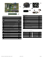
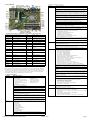
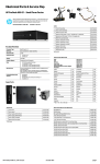
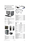
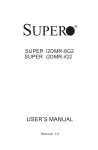
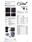
Illustrated Parts & Service Map
HP Compaq 8100 and 8180 Elite
Convertible Minitower Business PC
©2009, 2010, 2013 Hewlett-Packard Development Company, L.P. The information contained herein is subject to change without notice. HP shall not be liable
for technical or editorial errors or omissions contained herein. Intel, Pentium,
Intel Inside, and the Intel logo are trademarks or registered trademarks of the Intel
Corporation and its subsidiaries in the U. S. and other countries.
Document Number 605651-003.
3rd Edition January 2013.
Cables
Key Specifications
Processor Type
Intel® Core™ i7, i5, and i3; Intel Pentium
RAM Type
DDR3-SDRAM DIMMs, PC3-10600 (1333 MHz) non-ECC
Maximum RAM Supported
16 GB
Expansion Slots
•
•
•
Chipset
(2) PCIe-x16
(1) PCIe-x1
(3) PCI
1
Power switch/LED assembly
593218-001
2
Front USB, I/O assembly, power switch
593219-001
3
eSATA port assembly
497726-001
4
SATA cable, hard drive
593222-001
5
SATA cable, 17.7 inch, 2 straight ends
453317-001
*
Optical drive power cable
593223-001
*
SATA cable, 18 inch, 1 straight end, 1 angled end
393958-001
*
SATA cable, 24 inch
392308-001
*
DMS-59 to dual VGA cable
463023-001
*
DMS-59 to dual dongle
339527-001
*
Adapter, DVI to VGA
202997-001
*
Adapter, DisplayPort to VGA
603250-001
*
Adapter, DisplayPort to DVI
484156-001
*Not shown
Intel Q57 Express
Graphics Adapter
Integrated Intel Graphics Media Accelerator HD
Bays
•
•
I/O Interfaces
Front: (4) USB, microphone, headphone
Rear: (6) USB, PS/2 keyboard and mouse, line in, line out,
VGA, DisplayPort, RJ-45, serial port
Operating Systems
•
•
•
•
Keyboards (not illustrated)
(3) external 5.25-inch
(3) external 3.5-inch
PS/2, Basic
USB, Basic
USB SmartCard
USB Mini[b]
Washable[b]
Windows® Vista
Windows 7
Windows XP
FreeDos
Spare Parts
537745-xxx
537746-xxx
537747-xxx
535873-xxx
577495-xxx
Arabic[a]
-171
LA Spanish
-161
Belgian[c]
-181
Norwegian
-091
BHCSY[c]
-B41
People’s Republic of China
-AA1
BHCSY[d]
-BL1
Portuguese
-131
Brazilian Portuguese
-201
Romanian[c]
-271
Czech
-221
Russian
-251
Danish
-081
Saudi Arabia
-DE1
Finnish
-351
Slovakian
-231
French
-051
South Korea
-KD1
French Canadian
-121
Spanish
-071
German
-041
Swedish
-101
Greek
-151
Swiss
-111
Hebrew
-BB1
Taiwanese
-AB1
Hungarian
-211
Thai
-281
International[a]
-B31
Turkish
-141
International English
-L31
U.S.
-001
Italian
-061
U.K.
-031
Japanese
-291
[a] not for 537745
[b] only for -001, -121
[c] not for 537747
[d] only for 537747
Mass Storage Devices (not illustrated)
System Unit
1
Access panel
594636-001
2
Front bezel for use in 8100 models
593221-001
3
Front bezel for use in 8180 models
608265-001
4
Chassis
not spared
5
Power supply, 325W, 89% efficient
508154-001
*
*
5.25-inch bezel blank, jack black
Power supply, 325W
570838-001
508153-001
16X SATA DVD±RW and CD-RW drive with LightScribe
581600-001
16X SATA DVD-ROM drive
581599-001
Blu-ray ROM DVD+/-RW SuperMulti DL Drive
581601-001
1 TB (10000 GB) SATA hard drive
585465-001
500 GB SATA hard drive, 3.5-inch
504339-001
320 GB USB hard drive
591387-001
320 GB SATA hard drive, 3.5-inch
504338-001
250 GB SATA hard drive
606179-001
250 GB USB hard drive
586383-001
160 GB, 10000-RPM SATA hard drive, 2.5-inch with adapter
508312-001
160 GB SATA hard drive
606178-001
64 GB Solid State Drive (SSD)
581057-001
* Not shown
8100 & 8180 Elite IPSM, CMT Chassis
605651-003
page 1
Miscellaneous Parts
Standard and Optional Boards
System boards with thermal grease, alcohol pad, and CPU socket cover
1
System board
531990-001
*
System board, excludes ES/CS
606174-001
Memory modules (PC3-10600, CL9)
2
1 GB
576109-001
*
2 GB
576110-001
*
4 GB
585157-001
Other boards
*
HP WLAN 802.11 b/g/n for use world-wide, includes bracket
538048-001
*
Modem, PCIe, 56K, Agere International 56K, includes bracket
490689-001
*
ATI HD4550 (RV710), 256-MB PCIeX16 graphics card
584217-001
*
ATI HD4650 DP (RV730), 1-GB PCIeX16 graphics card
538052-001
*
GeForce 310 DP, 512-MB PCIeX16 graphics card
572029-001
*
nVidia Quadro NVS295, 256-MB PCIe graphics card
578226-001
*
nVidia Quadro NVS290, 256-MB graphics card, full-height
456137-001
*
Broadcom NetXtreme Gbit Ethernet Plus NIC
488293-001
*
Intel CT Gigabit NIC
490367-001
*
HP TV Tuner (North America) PCIe x1 Card
582725-001
*
HP FireWire / IEEE 1394a PCIe x1 Card, full height
515182-001
1
Fan, heat sink
593217-001
2
Speaker
392413-001
3
Chassis fan
593220-001
4
2nd serial port
392414-001
*
Card reader, 22-in-1
480032-001
*
Adapter, 5.25-inch to 3.25-inch, includes bezel
593226-001
*
Adapter, 2.5-inch
586721-001
*
Hood sensor
392417-001
*
Grommet, hard drive isolation
594220-001
*
Solenoid lock
392416-001
*
USB powered speakers
571536-001
*
Mouse, PS2, optical, jack black
537748-001
*
Mouse, optical, jack black
537749-001
*
Mouse, laser, jack black
570580-001
*
Printer port
497727-001
*
Modem cable
198220-001
*
Hard drive, removable carrier assembly
593224-001
*
Clamp lock, includes universal cable (plate not included)
508987-001
*
Foot kit
370708-001
*Not shown
Intel Quad-Core processors (8-MB L3 cache)
*
Core i7-870, 2.93-GHz processor
586378-001
*
Core i7-860, 2.80-GHz processor
586377-001
Modem RJ-11 adapters (not illustrated)
*
Core i5-750, 2.66-GHz processor
586376-001
Austrian
417561-011
Italian
316904-065
*
Core i5-750s, 2.40-GHz processor
606180-001
Belgian
316904-181
Netherlands
316920-335
Intel Dual-Core processors (4-MB L3 cache)
Czechoslovakian
234963-221
Polish
316904-241
*
Core i5-670, 3.46-GHz processor
604616-001
French
316904-051
Saudi Arabian
316904-AR1
*
Core i5-660, 3.33-GHz processor
604615-001
German
316904-045
Scandinavian
382848-DH1
*
Core i5-650, 3.20-GHz processor
604614-001
Greek
316904-151
Swiss
417562-111
*
Core i3-540, 3.06-GHz processor
604613-001
Hungarian
234963-215
Turkish
316904-141
*
Core i3-530, 2.93-GHz processor
604612-001
Israel
316904-BB1
United Kingdom
158593-035
Intel Pentium processor (3-MB L3 cache)
*
Pentium G6950 2.80-GHz processor
604623-001
* Not shown
8100 & 8180 Elite IPSM, CMT Chassis
605651-003
page 2
System Board
Computer Setup Menu (Continued)
Heading
Option / Description
Security
Setup Password - Allows you to set and enable the setup (Administrator)
password.
Power-On Password - Allows you to set and enable power-on password.
Password Options - When any password exists allows you to lock legacy
resources, enable/disable network server mode, specify password requirement for warm boot, allows enable/disable Setup Browse Mode, allows
enable/disable stringent password, allows enable/disable password prompt.
Smart Cover (some models) - Allows you to lock/unlock cover lock and set
status of cover removal sensor.
Device Security (some models) - Enables/disables all I/O ports, audio, network controllers, SATA ports, eSATA, and embedded security devices.
USB Security - Allows you to set Device Available/Device Hidden for front
USB ports 3-6, rear USB ports 7-12, internal USB ports 1-2.
Slot Security - Allows you to disable any PCI or PCI Express slot.
Network Service Boot - Enables/disables boot from OS on a server.
System IDs - Allows you to set Asset tag, Ownership tag, Chassis serial
number, UUID, and keyboard locale setting.
DriveLock Security - Allows you to assign/modify a hard drive password
for added security.
FRONT AUD Front audio connector
BAT
X4PCIEXP
PCIe x4 connector
SATA PWR1 Hard drive power connector
System Security (some models) - Allows you to enable/disable:
• Data Execution Prevention
• PAVP (Protect Audio Video Path) (some models)
• Virtualization Technology
• Virtualization Technology Directed I/O
• Trusted Execution Technology
• Embedded Security Device Support
• OS management of Embedded Security Device
• Smart card BIOS password support
X16PCIEXP
PCIe x16 connector
SATA PWR0 Optical drive power connector
Master Boot Record Security - Protects the master boot record from viruses
or other corruption. Saves of copy of the current master boot record.
X1PCIEXP1
PCIe x1 connector
PWRCMD
System power connector
CHFAN
Rear chassis fan connector
PWR
Main power
Setup Security Level - Provides method to allow users limited access to
change specified setup options without knowing Setup password.
IN/OUT
Audio ports
MEDIA
Card reader connector
RJ45/USB
Network/USB ports
FRONT
USB2
Internal USB connector
USB
USB ports
PB/LED
Front power button/LED
connector
VGA COM
Monitor connector/serial port
FRONT USB Internal USB connector
DISPLAYPORT
DisplayPort connector
PSWD
Password jumper
PS2
Keyboard/mouse connectors
MEDIA2
External media device connector
PWRCPU
CPU power
SPKR
Speaker connector
HLCK
Solenoid hood lock connector SATA0SATA3
System Board Connectors and Jumpers (component location may vary)
Battery socket
Power
Hardware Power Management - Allows you to enable/disable SATA bus
power management and S5 maximum power savings.
Thermal - Allows you to control minimum permitted fan idle speed.
Advanced
Drive connectors
HSENSE
Chassis intrusion switch
ESATA
eSATA drive connector
XU1
Processor socket
PCI1-PCI3
PCI connectors
CPUFAN
CPUFAN
COMB
Serial port connector
DIMM1DIMM4
Memory sockets
PAR
Parallel connector
CMOS
Clear CMOS button
OS Power Management - Allows you to enable/disable Runtime Power
Management, Idle Power Savings, ACPI S3 Hard Disk Reset, ACPI S3 PS2,
Unique Sleep State Blink Rates.
Power-On Options - Allows you to set:
• POST mode-QuickBoot, FullBoot, Clear Memory, FullBoot every x days
• POST messages - Enable/disable
• F9 prompt - Hidden/displayed
• F10 prompt - Hidden/displayed
• F11 prompt - Hidden/displayed
• F12 prompt - Hidden/displayed
• Factory Recovery Boot Support - Enable/disable
• Option ROM prompt - Enable/disable
• Remote wakeup boot source - Remote server/local hard drive
• After Power Loss - Off/on/previous state
• Multi-processor - Enable/disable
• Hyper-threading - Enable/disable
• POST delay - None, 5, 10, 15, or 20 seconds
• Limit CPUID Maximum Value to 3 - Enable/disable
• Bypass F1 Prompt on Configuration Changes - Enable/disable
Execute Memory Test (some models) -Restarts computer and executes
POST memory test.
System Setup and Boot
BIOS Power-On - Allows you to set the computer to turn on at a preset time.
Basic system information regarding system information, setup, power management, hardware,
and passwords is maintained in the Setup Utility held in the system ROM. The Setup Utility is
accessed by pressing the F10 key when prompted (on screen) to do so during the boot sequence.
If the screen prompt opportunity is missed, a restart will be necessary. For more information
about Setup Utilities refer to the Maintenance and Service Guide.
Onboard Devices - Allows you to set resources or disable onboard system
devices.
Computer Setup Menu
Heading
Option/Description
File
System Information - Lists the following main system specifications:
•
•
•
•
•
•
Product name
SKU number (some models)
Processor type/speed/stepping
Cache size (L1/L2)
Installed memory size/speed/
channels
Integrated MAC Address
•
•
•
•
•
PCI Devices - Lists installed PCI devices with their IRQ settings and allows
you to reconfigure IRQ or disable devices.
PCI VGA Configuration - Displayed only if multiple PCI video adapters
installed. Allows you to specify which VGA controller will be the boot or
primary VGA controller.
Bus Options (some models) - Allows you to enable/disable PCI SERR#
Generation and PCI VGA palette snooping.
Device Options - Allows you to set:
• Printer Mode - Bi-Directional, EPP & ECP, Output Only
• Num Lock state at power-on - off/on
• S5 Wake on LAN - enable/disable
• Internal speaker - enable/disable
• NIC Option ROM Download - enable/disable
• Turbo Mode - enable/disable
System BIOS
Chassis serial number
Asset tracking number
ME firmware version
Management node
Management Devices - Only displayed in Advanced menu when BIOS
detects multiple management options.
About - Displays copyright notice.
Set Time and Date - Allows you to set system time and date.
Flash System ROM - Allows you to select a drive containing a new BIOS.
Replicated Setup - Save to Rmv Media and Restore from Rmv Media
Default Setup
• Save Current Settings as Default
• Restore Factory Settings as Default
Apply Defaults and Exit - Applies the selected default settings and clears
any established passwords.
Management Operations - Allows you to set:
• MEBx Setup Prompt - enable/disable
• Intel Remote PC Assist Prompt - enable/disable
• Intel Remote PC Assist Timeout - 5, 10, 15, 20, 30, 40, 50, 60, 120, 180,
240 seconds
• SOL Terminal Emulation Mode - enable/disable
• SOL Keyboard - enable/disable
• Unprovision AMT on next boot - allows reset of AMT settings
Ignore Changes and Exit - Exits Computer setup without saving changes.
Save Changes and Exit - Saves changes to system configuration or default
settings and exits Computer Setup.
Storage
Device Configuration - Lists all installed BIOS-controlled storage devices.
The following options are available:
• CD-ROM
• Hard Disk
• Default Values
• SATA Defaults
• Translation Mode
• Removable Media Boot
• eSATA Port
• Max eSATA Speed
• SATA Emulation
DPS Self-Test - Allows you to execute self-tests on ATA hard drives.
Boot Order - Allows you to specify boot order.
• Shortcut to Temporarily Override Boot Order
8100 & 8180 Elite IPSM, CMT Chassis
605651-003
page 3
Password Security
This computer supports two security password features that are established through the
Computer Setup Utilities menu: setup password and power-on password. When you establish
only a setup password, any user can access all the information on the computer except Computer
Setup. When you establish only a power-on password, the power-on password is required to
access Computer Setup and any other information on the computer. When you establish both
passwords, only the setup password will give you access to Computer Setup.
When both passwords are set, the setup password can also be used in place of the power-on
password as an override to log in to the computer.
If you forget the password for the computer, you can clear that password so you can gain access
to the information on the computer by resetting the password jumper.
Clearing and Resetting CMOS
The computer’s configuration memory (CMOS) stores information about the computer’s configuration. The CMOS button resets CMOS but does not clear the power-on and setup passwords. Clearing CMOS will clear the Active Management Technology (AMT) settings in the
Management Engine BIOS Extension (MEBx), including the password. The password will
default to “admin” and will need to be reset. The AMT settings will also need to be reset. To
access the MEBx, press Ctrl+P during POST.
Red LED,
5 blinks/sec,
2 sec pause
5
Pre-video memory
error.
1. Reseat DIMMs.
2. Make sure a DIMM is installed in black
DIMM connector first if only one DIMM.
3. Replace 3rd-party with HP memory.
4. Replace system board.
Red LED,
6 blinks/sec,
2 sec pause
6
Pre-video graphics
error.
For systems with a graphics card:
1. Reseat graphics card.
2. Replace graphics card.
3. Replace system board.
For systems with integrated graphics,
replace system board.
Red LED,
7 blinks/sec,
2 sec pause
7
System board failure
(ROM detected failure
prior to video).
Replace system board.
Red LED,
8 blinks/sec,
2 sec pause
8
Invalid ROM based on
bad checksum.
1. Reflash system ROM with latest BIOS
image.
2. Replace system board.
Red LED,
9 blinks/sec,
2 sec pause
9
System powers on but is
unable to boot.
1. Check that voltage selector, located on the
rear of power supply (some models), is set to
appropriate voltage. Proper voltage setting
depends on region.
2. Unplug power cord from computer, wait
30 seconds, plug back in.
3. Replace system board.
4. Replace processor.
Red LED,
10 blinks/
sec, 2 sec
pause
10
Bad option card.
1. Check each option card by removing the
card (one at a time if multiple cards), then
power on system to see if fault goes away.
2. Once bad card identified, remove and
replace bad option card.
3. Replace system board.
Red LED,
11 blinks/
sec, 2 sec
pause
11
The current processor
does not support a feature previously enabled
on this system.
1. Install a TXT capable processor.
2. Disable TXT in Computer Setup (F10)
utility.
3. Reinstall original processor.
1. Turn off the computer and any external devices, and disconnect the power cord.
2. Disconnect the keyboard, monitor, and any other external equipment.
3. Remove the access panel.
4. Locate, press, and hold the CMOS button in for five seconds.
5. Replace the access panel.
6. Reconnect the external devices.
7. Plug in the computer and turn on power.
Clearing or Disabling a Power-On or Setup password
1. Shut down the operating system properly, then turn off the computer and any external
devices, and disconnect the power cord.
2. With the power cord disconnected, press the power button again to drain any residual power.
System does None System unable to power
on.
not power
on and
LEDs are
not flashing
3. Remove the access panel.
4. Locate the header and jumper. The password jumper is green.
5. Remove the jumper from pins 1 and 2. Place the jumper on either pin 1 or 2, but not both.
6. Replace the access panel.
7. Reconnect the external equipment.
8. Plug in the computer and turn on power. Allow the operating system to start. This clears the
current passwords and disables the password features.
9. To establish new passwords, repeat steps 1 through 4, replace the password jumper on pins 1
and 2, then repeat steps 6 through 8. Establish the new passwords in Computer Setup.
Hewlett-Packard Vision Diagnostics
The Hewlett-Packard Vision Diagnostics utility allows you to view information about the hardware configuration of the computer and perform hardware diagnostic tests on the subsystems of
the computer. The utility simplifies the process of effectively identifying, diagnosing, and isolating hardware issues.
Use HP Vision Diagnostics to determine if all the devices installed on the computer are recognized by the system and functioning properly. Running tests is optional but recommended after
installing or connecting a new device.
To access HP Vision Diagnostics, you must create a Recovery Disc Set then boot to the CD containing the utility. It can also be downloaded from http://www.hp.com and either burned to CD
or installed to a USB flash drive.
Press and hold power button for less than 4
seconds. If hard drive LED turns green,
power button working correctly. Try the following:
1. Check that voltage selector (some models), located on the rear of power supply, is
set to appropriate voltage. Proper voltage
setting depends on region.
2. Replace system board.
OR
Press and hold power button for less than 4
seconds. If hard drive LED does not turn on
green then:
1. Check that unit plugged into a working
AC outlet.
2. Open hood and check that power button
harness is properly connected to system
board.
3. Check that both power supply cables are
properly connected to system board.
4. Check if 5V_aux light on system board is
turned on. If yes, replace power button harness. If problem persists, replace system
board.
5. If 5V_aux light on system board is not
turned on, remove expansion cards one at a
time until 5V_aux light on system board
turns on. It problem persists, replace power
supply.
1. In Windows Explorer, go to C:\SWSetup\ISOs and burn the file Vision Diagnostics.ISO to a
CD or copy it to a USB flash drive.
Common POST Error Messages
2. While the computer is on, insert the CD in the optical drive or USB flash drive in a USB port.
Screen Message
Probable Cause
Recommended Action
101-Option ROM
Error
1. System ROM checksum
error.
1. Verify ROM, reflash if required
2. Expansion board option
ROM checksum
3. Clear CMOS memory
3. Shut down the operating system and turn off the computer.
4. Turn on the computer. The system will boot into HP Vision Diagnostics.
NOTE: If the system does not boot to the CD in the optical drive or to the USB flash drive,
you may need to change the boot order in the Computer Setup (F10) utility.
5. At the boot menu, select either the HP Vision Diagnostics utility to test the various hardware
components in the computer or the HP Memory Test utility to test memory only.
NOTE: The HP Memory Test is a comprehensive memory diagnostic utility that is run as a
stand-alone application, outside of HP Vision Diagnostics.
6. If running HP Vision Diagnostics, select the appropriate language and click Continue.
4. If message disappears, may be
problem with expansion card
5. Replace system board
103-System Board
Failure
DMA, timers
164-Memory Size
Error
Incorrect memory configuration
1. Clear CMOS memory.
2. Remove expansion boards.
7. In the End User License Agreement page, select Agree if you agree with the terms. The HP
Vision Diagnostics utility launches with the Survey tab displayed.
3. Replace system board.
Diagnostic LEDs
1. Run Setup (F10).
2. Check DIMMs for proper seating,
type, and HP compatibility.
3. Remove DIMMs singularly and
reboot to isolate faulty DIMM.
Activity
Beeps Possible Cause
Recommended Action
Green pwr
LED On
None Computer on.
None.
Green LED,
1 blink/2
seconds
None Computer in Suspend to None required. Press any key or move the
RAM mode (some mod- mouse to wake the computer.
els
only) or normal Suspend
mode.
Red LED, 1
blink/sec, 2
sec pause
2
4. Replace system board.
Processor thermal protection activated: A fan
may be blocked or not
turning.
OR
The heat sink/fan
assembly is not properly
attached to the processor.
1. Ensure computer air vents not blocked
and processor cooling fan running.
2. Open hood, press power button, see if
processor fan spins. If not spinning, make
sure fan's cable plugged onto system board
header.
3. If fan plugged in, but not spinning,
replace heat sink/fan assembly.
Red LED,
3 blinks/sec,
2 sec pause
3
Processor not installed
(not an indicator of bad
processor).
1. Check if processor is present.
2. Reseat processor.
Red LED,
4 blinks/sec,
2 sec pause
4
Power failure (power
supply is overloaded).
1. Open hood and ensure the 4 or 6-wire
power supply cable is seated into connector
on system board.
2. Check if a device is causing the problem
by removing ALL attached devices. Power
on system. If system enters the POST, then
power off and replace one device at a time
and repeat until failure occurs. Replace
device causing failure. Continue adding
devices one at a time to ensure all devices
functioning properly.
3. Replace the power supply.
4. Replace the system board.
8100 & 8180 Elite IPSM, CMT Chassis
2. Remove suspected card, reboot
214-DIMM Config- Populated DIMM configura- Rearrange DIMMs so that each channel
uration Warning
tion is not optimized
has the same amount of memory.
301-, 304-Keyboard Keyboard failure.
error
501-Display
Adapter Failure
Graphics display controller.
Check keyboard connection or keys.
Check connector for bent of missing
pins. Replace keyboard. If 304, possible
system board problem.
1. Reseat graphics card.
2. Clear CMOS.
3. Check monitor connection.
4. Replace graphics card.
1720-SMART Hard
Drive Detects
Imminent Failure
Hard drive is about to fail.
1. Determine if hard drive is giving
correct error message. Enter
Computer Setup and run the Drive
Protection System test under Storage
> DPS Self-test.
2. Apply hard drive firmware patch if
applicable.
3. Back up contents and replace hard
drive.
1796-SATA
Cabling Error
One or more SATA devices
are improperly attached. For
optimal performance, the
SATA 0 and SATA 1 connectors must be used before
SATA 2 and SATA 3.
Ensure SATA connectors are used in
ascending order. For one device, use
SATA 0. For two devices, use SATA 0
and SATA 1. For three devices, use
SATA 0, SATA1, and SATA 2.
1801-Microcode
Patch Error
Processor not supported by
ROM BIOS.
1. Upgrade BIOS to proper version.
605651-003
2. Change the processor.
page 4