1
V2401/2402 Series
WinXP Embedded User’s Manual
First Edition, February 2010
www.moxa.com/product
© 2010 Moxa Inc. All rights reserved.
Reproduction without permission is prohibited.
V2401/2402 Series
WinXP Embedded User’s Manual
The Moxa software described in this manual is furnished under a license agreement and may be used only in
accordance with the terms of that agreement.
Copyright Notice
Copyright © 2010 Moxa Inc.
All rights reserved.
Reproduction without permission is prohibited.
Trademarks
MOXA is a registered trademark of Moxa Inc.
All other trademarks or registered marks in this manual belong to their respective manufacturers.
Disclaimer
Information in this document is subject to change without notice and does not represent a commitment on the
part of Moxa.
Moxa provides this document “as is,” without warranty of any kind, either expressed or implied, including, but
not limited to, its particular purpose. Moxa reserves the right to make improvements and/or changes to this
manual, or to the products and/or the programs described in this manual, at any time.
Information provided in this manual is intended to be accurate and reliable. However, Moxa assumes no
responsibility for its use, or for any infringements on the rights of third parties that may result from its use.
This product might include unintentional technical or typographical errors. Changes are periodically made to the
information herein to correct such errors, and these changes are incorporated into new editions of the
publication.
Technical Support Contact Information
www.moxa.com/support
Moxa Americas:
Toll-free: 1-888-669-2872
Tel: +1-714-528-6777
Fax: +1-714-528-6778
Moxa China (Shanghai office):
Toll-free: 800-820-5036
Tel: +86-21-5258-9955
Fax: +86-10-6872-3958
Moxa Europe:
Tel: +49-89-3 70 03 99-0
Fax: +49-89-3 70 03 99-99
Moxa Asia-Pacific:
Tel: +886-2-8919-1230
Fax: +886-2-8919-1231
Table of Contents
Chapter 1
Introduction ..................................................................................................1-1
Overview.................................................................................................................................. 1-2
Software Specifications ........................................................................................................... 1-2
Application Development Environment ....................................................................... 1-2
Networking and Communication Capabilities.............................................................. 1-4
Supporting Services and Daemons ............................................................................... 1-5
How to Determine Firmware Build Versions........................................................................... 1-5
Inserting a USB Mass Storage Device into the Computer ....................................................... 1-6
Inserting an CF Card in the Computer ..................................................................................... 1-7
Inserting a SATA Hard disk into a V2400 Computer ............................................................... 1-8
Four RS-232/422/485 Serial Ports................................................................................ 1-9
Digital Input/Output Channels...................................................................................... 1-9
Eight RS-232 Serial Ports (V2401 only)................................................................................ 1-13
Chapter 2
Software Configuration ...............................................................................2-1
Starting Your V2401/2402-XPE Computer.............................................................................. 2-2
Resetting Your V2401/2402-XPE Computer ........................................................................... 2-2
Changing the LVDS Settings ................................................................................................... 2-3
Changing the Network Settings ............................................................................................... 2-5
Operating Your V2401/2402-XPE Computer with a Telnet Client .......................................... 2-6
Adjusting the System Time ...................................................................................................... 2-7
Starting and Stopping Services ................................................................................................ 2-8
Simple Network Management Protocol (SNMP)..................................................................... 2-9
Remote Desktop (RDP) ........................................................................................................... 2-9
Serial Ports............................................................................................................................. 2-10
Enhanced Write Filter .............................................................................................................2-11
File Based Write Filter ............................................................................................................2-11
Chapter 3
Management Tools.......................................................................................3-1
Computer Management............................................................................................................ 3-2
Component Services ................................................................................................................ 3-3
Event Viewer............................................................................................................................ 3-4
Internet Information Services (Web/FTP)................................................................................ 3-5
ODBC Data Source Administrator......................................................................................... 3-12
Performance Monitor ............................................................................................................. 3-13
Services.................................................................................................................................. 3-14
Chapter 4
System Recovery .........................................................................................4-1
Recovery Environment ............................................................................................................ 4-2
Recovery Procedure ................................................................................................................. 4-2
1
Chapter 1
Introduction
Thank you for purchasing the Moxa’s V2401/2402 series of x86 ready-to-run embedded
computers. This manual introduces the software configuration and management of V2401/2402
computers running the Windows Embedded Standard 2009 operating system. For hardware
installation, connector interfaces, setup procedures, and upgrading the BIOS, please refer to the
V2401/2402 Series Hardware User’s Manual.
Microsoft Windows Embedded Standard 2009 is a specialized operating system consisting of
componentized Windows XP Professional features that allows you to build a wide range of
innovative, small footprint devices. Windows developers will find Moxa’s V2401/2402 computer
plus Windows Embedded Standard 2009 operating system to be the right solution for a wide range
of applications.
In this chapter, we cover the following topics:
Overview
Software Specifications
¾ Application Development Environment
¾ Networking and Communication Capabilities
¾ Supporting Services and Daemons
How to Determine Firmware Build Versions
Inserting a USB Mass Storage Device into the Computer
Inserting an CF Card in the Computer
Inserting a SATA Hard disk into a V2400 Computer
¾ Four RS-232/422/485 Serial Ports
¾ Digital Input/Output Channels
Eight RS-232 Serial Ports (V2401 only)
V2401/2402 WinXP User’s Manual
Introduction
Overview
The V2401 and V2402 come with four RS-232/422/485 serial ports, and the V2401 has an
additional eight RS-232 ports, making them ideal for connecting a wide range of serial devices.
The dual 10/100/1000 Mbps Ethernet ports offer a reliable solution for network redundancy,
delivering continuous operations for data communication and management. As an added
convenience, the V2401/2402 computers have four DIs, and four DOs for connecting digital
input/output devices.
In addition, the CompactFlash and USB sockets provide the V2400 computers with the reliability
needed for industrial applications that require data buffering and storage expansion.
Pre-installed with Windows Embedded Standard 2009, the V2401/2402 Series provides
programmers with a friendly environment for developing sophisticated, bug-free application
software at a low cost.
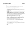
Software Specifications
The software features of the V2401/2402-XPE embedded computers are listed below:
Application Development Environment
The V2401/2402-XPE is fully compatible with the XP Professional Development Environment.
The V2401/2402-XPE’s use of Windows Embedded Standard 2009 with SP3 provides the
following common, popular application development features that make programming convenient
and easy.
Every application that runs in Windows XP can be executed in the V2401/2402-XPE, so there is
no migration cost.
Windows Embedded Standard 2009 is based on the same binary files as Windows XP Professional;
Windows Embedded Standard 2009 enables you to rapidly develop reliable and full-featured
connected devices.
y
Microsoft .Net Framework 3.5—This component includes the common language runtime
(CLR) and the .NET Framework class library.
y
Active Directory Service Interface (ADSI) Core—Provides the basic functionality for ADSI.
This component routes any requests to the corresponding provider according to the path it is
provided.
y
Active Template Library (ATL) —Supports ATL applications.
y
ASP.NET 2.0—A unified Web application platform that provides the services necessary to
build and deploy enterprise-class Web applications.
y
Certificate Request Client & Certificate Auto enrollment—This component includes the
common language runtime (CLR) and the .NET Framework class library.
y
COM Base—Component Object Model (COM) includes a programming model and a set of
application programming interfaces (APIs), and does not include a dedicated user interface.
y
Common Control Libraries—(Side by Side) the component provides common user interface
(UI) controls.
y
Common File Dialogs—Support for common dialog boxes.
y
Direct3D—The infrastructure for two-dimensional and three-dimensional graphics.
y
DirectPlay—Provides a networking API that can enable any application to operate over both
a peer-to-peer and client/server topology.
1-2
V2401/2402 WinXP User’s Manual
Introduction
y
DirectShow—Base filter graph and device enumeration support for all DirectShow
applications. This component also provides most DirectShow filters.
y
Distributed Transaction Coordinator (MSDTC) —A distributed transaction facility for
Microsoft Windows systems, which uses transaction-processing technology. MSDTC exploits
loosely coupled systems to provide scalable performance.
y
Enhanced Write Filter—An upper filter in the storage device driver stack that redirects disk
write operations to volatile (RAM) or non-volatile (disk) storage.
y
Event Log—A dynamic-link library (DLL) that runs as part of Services.exe. This component
stores and retrieves events that can be viewed in the event viewer.
y
Internet Explorer 7—The Internet Explorer Web browser that allows customers to connect to
the Internet or to an intranet (see properties via inetcpl.cpl).
y
Mapi32 Libraries—The infrastructure for e-mail support.
y
Message Queuing (MSMQ) Core—Message Queuing is a messaging infrastructure and a
development tool for creating distributed messaging applications for Microsoft Windows
operating systems; it provides guaranteed message delivery, efficient routing, increased
security, support for sending messages within transactions, and priority-based messaging.
y
Microsoft Visual C++ Run Time Libraries—The Microsoft C++ Runtime Library.
y
NTFS—The NTFS File System driver (NT File System). Use NTFS instead of FAT for
optimum file system security.
y
Power Management—This component includes a dynamic-link library for power
management features in the xpepm.dll file, and a command-line tool for using power
management on a run-time image in the xpepm.exe file. Note: Instead of using this
component, Shutdown.exe is the preferred method to shut down the system.
y
Registry Editor—The Registry Editor (regedit.exe, regedt32.exe).
y
RPC—Facilitates local remote procedure calls (RPCs) using the ncalrpc and ncacn_np
protocol sequences, and provides support for dynamic endpoint resolution. The RPC name
service provides remote procedure call (RPC) named services functionality, such as the RPC
Locator. The RPC Named Service component exposes all RpcNs* RPC functions. The RPC
server provides a variety of RPC and Component Object Model (COM) services, including
RPC Endpoint Mapper, COM Service Control Manager (SCM) and COM Object Resolver.
y
Smart Card Cryptographic Service Providers—Supports features such as smart card logon
and improved e-mail security. Smart cards must be capable of certain RSA public key
cryptographic operations. These functions are exposed by using CryptoAPI and, specifically,
through a CSP. Typically, each type of smart card requires a CSP, which is provided by the
card vendor.
y
USB 2.0—The core drivers needed to communicate with an Enhanced Host Controller
Interface (EHCI) that is compliant with USB .95 or 1.0.
y
Windows API—User—Provides the user-mode component of the Windows operating system
API.
y
Windows Media Player 11—Playback functionality for digital media that includes videos,
CDs, and DVDs for end users and developers.
y
Windows Script Engines—A complete scripting environment for Windows, including
command-line scripting, script languages, and the ability to host script engines within your
applications.
y
WMI—Bundles the features that combine to create the Windows Management
Instrumentation (WMI) technologies.
1-3
V2401/2402 WinXP User’s Manual
Introduction
Networking and Communication Capabilities
The V2401/2402-XPE embedded computers provide powerful hardware communication interfaces
for network-centric embedded applications, including 2 Ethernet and 2 serial ports, and also
support the networking and communications capabilities that are built into Windows Embedded
Standard 2009 with SP3 OS. The following features are supported:
y
DHCP Client Service—Registers and updates Internet Protocol (IP) addresses and Domain
Name System (DNS) records for your target system.
y
IP Security Services—This component provides IP Security (IPsec) services for all IP traffic.
y
Dial-Up Networking—Provides the infrastructure necessary to implement a Remote Access
Service (RAS) client.
y
Microsoft-Windows-HTTP—Services that implement the functionality of the HTTP protocol
on a server.
y
TCP/IP Networking—Implements the core TCP/IP protocol stack, which includes the IPv4
version for the following protocols: Transmission Control Protocol (TCP), User Datagram
Protocol (UDP), raw, Internet Control Message Protocol (ICMP), Internet Group Membership
Protocol (IGMP), and Address Resolution Protocol (ARP). The component also includes
Wshtcpip.dll, which is the Winsock provider for TCP/IP to enable socket-level
communication over TCP/IP.
y
TAPI—A Telephony API (TAPI) Telephony Service Provider (TSP).
y
Simple Network Management Protocol (SNMP)—SNMP is an agent service that provides
management systems with information about activities that occur at the Internet Protocol (IP)
network layer. The SNMP agent monitors network traffic, and retrieves and updates local
management information based on the requests from the SNMP manager. The agent also
notifies registered managers with traps when significant events occur.
y
Time Service Core—Synchronizes a workstation's clock with other computers using the
Network Time Protocol (NTP) version 3. For increased accuracy, this component also
incorporates algorithmic enhancements from NTP 4.
y
Windows Firewall/Internet Connection Sharing (ICS)—Windows Firewall provides a
barrier between your device and network connections to help reduce attacks by hackers,
viruses, and worms across networks. Strongly recommended..
y
Wireless Zero Configuration—Support for the Windows implementation of the IEEE 802.11
standard. This component performs automatic configuration and authentication for IEEE
802.11 wireless network adaptors.
y
Unimodem—Provides the infrastructure necessary for applications to communicate with a
modem.
1-4
V2401/2402 WinXP User’s Manual
Introduction
Supporting Services and Daemons
In addition to development and communication capability, the V2401/2402-XPE embeds the
services and daemons shown below. These common and easy-to-use application servers help users
migrate industrial communication applications to the V2401/2402-XPE embedded computer very
easily and conveniently.
y
COM+ Services—The next evolution of Microsoft Component Object Model (COM) and
Microsoft Transaction Server (MTS).
y
Computer Browser Service—Computer browsing functionality exposed by Windows
through Microsoft Networking. It allows a client machine to browse its network neighborhood
for available computers, exposing file and print sharing services.
y
Disk Management Services—Support for disk and volume management operations. The
component implements a Component Object Model (COM) interface that can be used to query
and configure disks and volumes (both basic and dynamic). The component also monitors disk
arrivals and removals and other changes in the storage subsystem.
y
IIS Web Server—Allows you to create and manage Web sites.
y
Terminal Server—Microsoft Terminal Server client application (mstsc.exe).
y
Remote Registry Service—Enables remote users to modify registry settings on this
computer.
y
Telnet Server—Allows users to connect to Telnet servers from remote computers.
How to Determine Firmware Build Versions
Use the mxver command to obtain the firmware version of the V2401/2402-XPE embedded
computer. This information is particularly important for identifying which features your embedded
computer supports.
y
Execute the mxver.exe command line utility.
C:\> mxver
Model Name: V2400-XPE
Build Date: 09110915
Version: V1.0
1-5
V2401/2402 WinXP User’s Manual
Introduction
Inserting a USB Mass Storage Device into the Computer
Inserting a USB mass storage device will generate a new drive on the V2401/2402-XPE. The new
drive should be visible in the File Explorer.
1-6
V2401/2402 WinXP User’s Manual
Introduction
Inserting an CF Card in the Computer
The V2401/2402-XPE computer is equipped with a CompactFlash slot for CompactFlash (CF)
card storage expansion support. Please make sure to turn off the computer before inserting the CF
card into the CF slot on the front panel.
The V2401/2402-XPE does not support CF “Plug and Play” and “Hot Swap.” Please make sure to
turn off the computer before inserting a new CF cards.
1-7
V2401/2402 WinXP User’s Manual
Introduction
Inserting a SATA Hard disk into a V2400 Computer
Before inserting a SATA hard disk, make sure that the computer is powered off. Insert a SATA
Hard disk device will create a new disk in the V2401/2402-XPE. You should see it in the File
Explorer.
1-8
V2401/2402 WinXP User’s Manual
Introduction
NOTE: The V2401/2402 embedded computer supplies only 5V DC power for 2.5 inch SATA
hard disks. If you want to use a 3.5 inch hard disk, you will need to use external power
supply for your SATA hard disk.
Four RS-232/422/485 Serial Ports
The serial ports of the V2401/2402-XPE computer from button to top are named “COM1” to
“COM4” COM1 to COM4 are RS-232/422/485 serial ports. Each of these ports supports baudrate
settings of up to 921.6 Kbps.
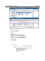
Digital Input/Output Channels
The V2401/2402 series provides four digital input and four digital output channels for controlling
digital signals. You can set the operation mode by programming; the example “DIO” can be found
under \examples\C++\ of the Software DVD.
The code snippet is as follows:
/*
index[n]: 0
; BIT 0
1
; BIT 1
2
; BIT 2
3
; BIT 3
....
data[n]: 0 ; Digital LOW
1
; Digital HIGH
1-9
V2401/2402 WinXP User’s Manual
Introduction
*/
unsigned int
hDIO;
unsigned int port_no;
int data;
int
intDout,intDin;
int
nDout=0;
int port=0,mode=0;
int n=0;
WCHAR sin,smode;
printf("UART Mode Test Program\n");
printf("\t (0) Exit Program\n");
printf("\t (1) Display DIN\n");
printf("\t (2) Display DOUT\n");
printf("\t (3) Set DOUT value\n");
printf("\t (4) Display both DIN and DOUT\n");
sin=getwchar();
n=_wtoi(&sin);
do
{
switch (n)
{
// if char == '1', display the digital input
case 1:
//Open dio
hDIO=mxdio_open();
for(int i=0;i<=3;i++)
{
//Get digital input
port_no=i;
intDin=mxdio_get_din(hDIO,port_no);
printf("Din%d = %d\n",port_no,intDin);
}
//Close DIO
1-10
V2401/2402 WinXP User’s Manual
Introduction
mxdio_close(hDIO);
break;
// if char == '2', display the digital output
case 2:
//Open dio
hDIO=mxdio_open();
for(int i=0;i<=3;i++)
{
//Get digital input
port_no=i;
intDin=mxdio_get_dout(hDIO,port_no);
printf("Dout%d = %d\n",port_no,intDin);
}
//Close DIO
mxdio_close(hDIO);
break;
// if char == '3', Set the digital output
case 3:
//Get Port Number
getwchar();
printf("Input the Port Number (0 ~ 3) = \n");
smode=getwchar();
port_no=_wtoi(&smode);
//Get Value
getwchar();
printf("Input the value (0 or 1) = ");
smode=getwchar();
data=_wtoi(&smode);
//Open DIO
hDIO=mxdio_open();
//Set DOUT
nDout=mxdio_set_dout(hDIO,port_no, data);
if(!nDout)
1-11
V2401/2402 WinXP User’s Manual
Introduction
{
printf("Set digital output fail!\n");
}
else
{
printf("Set digital output success!\n");
}
//Close DIO
mxdio_close(hDIO);
break;
case 4:
// if char == '4', Get both digital input and digital output
//Open dio
hDIO=mxdio_open();
for(int i=0;i<=3;i++)
{
//Get digital input
port_no=i;
intDin=mxdio_get_din(hDIO,port_no);
intDout=mxdio_get_dout(hDIO,port_no);
printf("Din%d = %d, Dout%d =
%d\n",port_no,intDin,port_no,intDout);
}
//Close DIO
mxdio_close(hDIO);
break;
}
getwchar();
sin = getwchar();
n = _wtoi(&sin);
} while (n != 0);
1-12
V2401/2402 WinXP User’s Manual
Introduction
Eight RS-232 Serial Ports (V2401 only)
The V2401 also offers eight RS-232 serial ports by connecting with a 68-pin VHDC cable. These
eight serial devices will be named “COM5” to “COM12”
Follow the steps below to set the operation mode of each COM port:
A.
Go to the Control Panel Æ Ports (COM & LPT) and select the COM port (ex. MOXA Port
0 (COM1)).
B.
Right-click the COM port and click Properties.
C.
At the Port Settings tab, select the interface you wish to use.
D.
Click OK to apply these settings.
1-13
V2401/2402 WinXP User’s Manual
Introduction
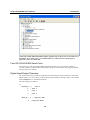
In some situations, you may want to change the port name to accommodate your program. Follow
the steps below to change the name of the ports:
A.
Go to the Control Panel Æ Multi-port serial adapters and select the adapter.
B.
Right-click the adapter and click Properties.
1-14
V2401/2402 WinXP User’s Manual
C.
Introduction
At the Port Configuration tab, select the port you want to change its name and then
click [Port Setting].
1-15
V2401/2402 WinXP User’s Manual
Introduction
D.
Uncheck “Auto Enumerating COM Number” if you want to change the port name
separately.
E.
Select the port name you want to change, and then press [OK].
1-16
V2401/2402 WinXP User’s Manual
F.
Introduction
Make sure the port names are correct, and then click [OK] to apply these settins.
1-17
V2401/2402 WinXP User’s Manual
G.
Introduction
Now, you can see that the port names have been changed under Ports (COM & LPT).
NOTE: Make sure each port name is unique, or the duplicate names will lead to inaccessible
devices.
1-18
V2401/2402 WinXP User’s Manual
Introduction
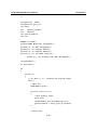
Also, you can set the operation mode by programming; the example “UartMode” can be found in
\examples\C++\ of the Software DVD.
The code snippet is as follows:
int port=0,mode=0;
int n=0;
WCHAR sin;
WCHAR wcs_port[3],wcs_mode[3];
printf("UART Mode Test Program\n");
printf("\t (0) Exit Program\n");
printf("\t (1) Display UART Mode\n");
printf("\t (2) Set UART Mode\n");
sin=getwchar();
n=_wtoi(&sin);
do
{
switch (n)
{
// if char == '1', display the UART Mode
case 1:
printf("Input the Port Number (1~4) = \n");
wscanf(L"%s",wcs_port);
port=_wtoi(wcs_port);
mode=uart_getmode(port);
if(mode==(-1))
{
1-19
V2401/2402 WinXP User’s Manual
Introduction
printf("Invalid value!!\n");
break;
}
printf("COM%d=%s\n",port,mode_array[mode]);
break;
// if char == '2', Set the UART Mode
case 2:
//Get Port Number
printf("Input the Port Number (1~4) = \n");
wscanf(L"%s",wcs_port);
port=_wtoi(wcs_port);
//Get Mode Value
printf("Input the Mode value (0 ~ 3) = ");
wscanf(L"%s",wcs_mode);
mode=_wtoi(wcs_mode);
//Set UART Mode
if(uart_setmode(port,mode)==-1)
{
printf("Invalid value!!\n");
printf("Set UART Mode Fail!!\n");
}
else
{
printf("COM%d=%s\n",port,mode_array[mode]);
}
break;
}
getwchar();
sin = getwchar();
n = _wtoi(&sin);
} while (n != 0);
return 0;
1-20
2
Chapter 2
Software Configuration
In this chapter, we explain how to operate a V2401/2402-XPE computer directly or from a PC.
Instructions are given on how to adjust the system time, troubleshoot network connectivity, and
manage other functions. Some of these operations can be done with system commands after
gaining access to the computer, and others can be done from the “Control Panel,” which is
described in a later chapter.
In this chapter, we cover the following topics:
Starting Your V2401/2402-XPE Computer
Resetting Your V2401/2402-XPE Computer
Changing the LVDS Settings
Changing the Network Settings
Operating Your V2401/2402-XPE Computer with a Telnet Client
Adjusting the System Time
Starting and Stopping Services
Simple Network Management Protocol (SNMP)
Remote Desktop (RDP)
Serial Ports
Enhanced Write Filter
File Based Write Filter
V2401/2402 WinXP User’s Manual
Software Configuration
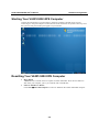
Starting Your V2401/2402-XPE Computer
Connect the CRT monitor or LCD monitor to the target computer, and then power it up by
connecting it to the power adaptor. It takes about 30 to 40 seconds for the system to boot up. Once
the system is ready, the Desktop will appear on your monitor.
Resetting Your V2401/2402-XPE Computer
y
Reset Button
A Reset button is located on the front panel of V2401/2402-XPE. Press the reset button to
shut down your computer, just as you would do with a standard PC.
y
Software Shutdown / Reboot
Click Start Æ Turn Off Computer to reboot or shutdown the V2401/2402-XPE computer.
2-2
V2401/2402 WinXP User’s Manual
Software Configuration
Changing the LVDS Settings
The V2401/2402-XPE computer comes with an LVDS connector, allowing users to connect an
LVDS display. Before you connect your LVDS panel to the embedded computer, be sure the
display settings match your LVDS panel. Use the following steps to adjust LVDS settings.
1. Select [Advanced] tab in the BIOS Menu.
2. Select [Advanced Chipset Features] and then select the [LCD Panel Type] and [Panel Data
Format] compatible with your LVDS panel.
3. Double-click the display icon at the bottom right of the screen
4. Select Graphics Properties. (Ex. Intel(R) Dual Display Clone mode for both CRT and LVDS
output)
2-3
V2401/2402 WinXP User’s Manual
Software Configuration
5. Select the Color Quality (32 bit or 18 bit), Screen Resolution, and Refresh Rate compatible
with your LVDS display. You may also select the Enable Rotation checkbox if you need
rotation functions.
6. You can also use hot keys to change your display settings. When finished, click Apply and
then OK.
2-4
V2401/2402 WinXP User’s Manual
Software Configuration
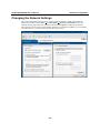
Changing the Network Settings
The V2401/2402-XPE computer comes with two network interfaces. Both of the default IP
addresses are DHCP. Choose Start Æ Control panel Æ Network Connections to enter the
network settings page. Select the connection and choose Properties on the pop-up menu by
right-clicking. You can specify the IP address manually or by DHCP. In addition, you can disable
or enable either one or both connections with the pop-up menu.
2-5
V2401/2402 WinXP User’s Manual
Software Configuration
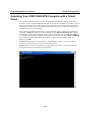
Operating Your V2401/2402-XPE Computer with a Telnet
Client
Use a crossover Ethernet cable to connect your development workstation directly to the target
computer, or use a straight-through Ethernet cable to connect the computer to a LAN hub or switch.
Next, use a telnet client on your development workstation to connect to the Telnet console utility
of the target computer. After a connection has been established, type the login name and password
as requested to log on to the computer.
After logging in through the Telnet client, a list of commands will be available for operating the
computer. Use HELP to display all of the commands, or type HELP [command name] to display
extended help for the selected command. Some of these commands, such as DATE and TIME, are
very useful for managing the computer’s system time. Other commands, such as DIR and MKDIR,
are good utilities for file management. For example, to inspect the file structure of the root
directory, type DIR.
NOTE: The default user id is “administrator” and the default password is not set; you need to
create a new password for this account to use this telnet client.
NOTE: There is a connection limitation on using Telnet clients. You are only allowed to create
connections with two Telnet clients at the same time.
2-6
V2401/2402 WinXP User’s Manual
Software Configuration
Adjusting the System Time
y
Setting the System Time Manually: Use the date/time command line utility to query the
current system date/time or set a new system date/time.
y
Date/Time Control panel: Go to the Control Panel and double click the Date and Time
icon.
2-7
V2401/2402 WinXP User’s Manual
y
Software Configuration
SNTP: In the Date and Time Properties window, you can see the NTP server setting.
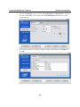
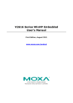
Starting and Stopping Services
Select Start Æ Control Panel Æ Administrative Tools and double click Services. Select and
right-click on the service name, and then choose to stop or start.
2-8
V2401/2402 WinXP User’s Manual
Software Configuration
Simple Network Management Protocol (SNMP)
To check SNMP agent capabilities on a target V2401/2402-XPE (e.g., suppose the network IP is
192.168.3.127) computer, log on to the workstation computer on which the SNMP manager resides
and then type:
\> snmpwalk -v 2c -c public 192.168.3.127 system
You will see a series of messages from the SNMP agent on the V2401/2402-XPE computer that
allow you to monitor and manage the computer.
Remote Desktop (RDP)
You can connect to the target V2401/2402-XPE computer remotely by using Remote Desktop.
Right-click My Computer on your desktop, and select Properties. Click the Remote tab for
further configuration.
2-9
V2401/2402 WinXP User’s Manual
Software Configuration
Make sure that the Allow users to connect remotely to this computer checkbox is selected. Next,
click Select Remote Users, and add the users allowed to connect to your desktop. When finished,
click OK.
Serial Ports
V2401/2402-XPE embedded computers have 4 serial ports on the back panel. These ports are
designed to provide reliable, high-speed, 3-in-1 (RS-232, RS-422, and RS-485) operation. Each of
the ports supports baudrates up to 115,200 bps.
The command line utility “SetInterface.exe” is for users to view and set the current operation
mode.
2-10
V2401/2402 WinXP User’s Manual
Software Configuration
Enhanced Write Filter
The “Enhanced Write Filter” protects the contents of a volume on the target media volume by
redirecting all writes to another storage location called on overlay. Use the following steps to
enable the Enhanced Write Filter.
1. Type EWFMGR C: to check if the state of the Enhanced Write Filter is Disabled.
2. To enable the filter, type EWFMGR C: -enable.
3. Reboot the system to activate the change.
4. Delete a file on your protected volume and reboot the system; the file you just deleted will
appear.
File Based Write Filter
File-Based Write Filter (FBWF) allows Windows Embedded Standard 2009 to maintain the
appearance of read and write access to write sensitive or read only storage. FBWF makes read and
write access transparent to applications.
Writing to storage media may be undesirable or impossible in embedded devices. FBWF redirects
all writes targeted for protected volumes to a RAM cache called an overlay. In this context, an
overlay can be likened to a transparency overlay on an overhead projector. Any change made to the
overlay affects the picture as seen in the aggregate, but if the overlay is removed, the underlying
picture remains unchanged.
2-11
V2401/2402 WinXP User’s Manual
Software Configuration
Follow the steps below to enable FBWF:
1. In the command prompt, type fbwfmgr /displayconfig to check the current FBWF status. The
status defaults to disabled.
C:\>fbwfmgr /displayconfig
File-based write filter configuration for the current session:
Filter state: disabled.
File-based write filter configuration for the next session:
Filter state: disabled.
C:\>
2. Type fbwfmgr /enable to enable FBWF. Reboot the system for the changes to come into
effect.
C:\>fbwfmgr /enable
File-based write filter will be enabled on the next reboot.
C:\>
3. When the system has rebooted, type fbwfmgr /displayconfig in the command prompt again to
confirm thatthe status has been changed to enabled. The default folder for FBWF will be
\temp. Type fbwfmgr /help for more detailed information.
C:\> fbwfmgr /displayconfig
File-based write filter configuration for the current session:
filter state: enabled.
overlay cache data compression state: disabled.
overlay cache threshold: 64 MB.
overlay cache pre-allocation: disabled.
size display: actual mode.
protected volume list:
\Device\HarddiskVolume3
write through list of each protected volume:
\Device\HarddiskVolume3:
\temp
File-based write filter configuration for the next session:
filter state: enabled.
overlay cache data compression state: disabled.
overlay cache threshold: 64 MB.
overlay cache pre-allocation: disabled.
size display: actual mode.
protected volume list:
\Device\HarddiskVolume3
write through list of each protected volume:
\Device\HarddiskVolume3:
\temp
C:\
2-12
V2401/2402 WinXP User’s Manual
Software Configuration
4. You may copy a file (in this example, we will use TestFile.txt) to C:\temp and to C:\, and then
reboot the system.
5. After rebooting the system, you should see that the file in C:\ has disappeared and that the file
in C:\temp remains.
2-13
3
Chapter 3
Management Tools
The V2401/2402-XPE ready-to-run embedded computers are shipped with the Windows
Embedded Standard 2009 operating system already installed. This network-centric platform is
designed to serve as a front-end for data acquisition and industrial control applications. A set of
Windows XP management tools are installed on the V2401/2402-XPE computer to resolve
management issues.
In this chapter, we cover the following topics:
Computer Management
Component Services
Event Viewer
Internet Information Services (Web/FTP)
ODBC Data Source Administrator
Performance Monitor
Services
V2401/2402 WinXP User’s Manual
Management Tools
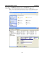
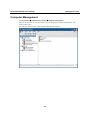
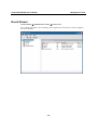
Computer Management
[Control Panel] Æ [Administrative Tools] Æ Computer Management.
You can use the tools for a variety of tasks, such as disk partition, disk mount/dismount, and
create/remove users.
You can also check services in the Computer Management window.
3-2
V2401/2402 WinXP User’s Manual
Management Tools
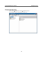
Component Services
[Control Panel] Æ [Administrative Tools] Æ Component Services.
You can install/view/remove COM components with this tool.
3-3
V2401/2402 WinXP User’s Manual
Management Tools
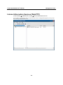
Event Viewer
[Control Panel] Æ [Administrative Tools] Æ Event Viewer.
Every V2401/2402-XPE event, including system, applications, and security events are logged in
this event database.
3-4
V2401/2402 WinXP User’s Manual
Management Tools
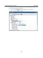
Internet Information Services (Web/FTP)
[Control Panel] Æ [Administrative Tools] Æ Internet Information Services.
If you need to set up Web or FTP, you must use this tool for configuration purposes, and you can
also start/stop HTTP/FTP services.
3-5
V2401/2402 WinXP User’s Manual
Management Tools
A default web page is located in the directory c:\Inetpub. Use this default page to test your web
server.
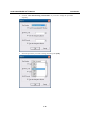
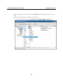
Follow the steps shown below to create the virtual directory.
1. Create a virtual directory by selecting Default Web Site Æ New Æ Virtual Directory.
3-6
V2401/2402 WinXP User’s Manual
Management Tools
2. Follow the virtual directory creation wizard and complete the steps to create the virtual
directory c:\Inetpub.
3-7
V2401/2402 WinXP User’s Manual
Management Tools
Type the alias into the text box. Click Next to continue.
3-8
V2401/2402 WinXP User’s Manual
Management Tools
3-9
V2401/2402 WinXP User’s Manual
Management Tools
3. When you complete the steps, the virtual directory WEB will appear under Default WEB
Site.
4. On your desktop, type [IP Address]/WEB/Default.htm
(e.g., 192.168.1.127/WEB/Default.htm). The following message will appear. The steps are
indicated in the following sequence of diagrams.
3-10
V2401/2402 WinXP User’s Manual
Management Tools
If you need to use the FTP server, you must create the default password for your account and turn
on the write permission on your home directory located in c:\intepub\ftproot. Select FTP Sites Æ
Default FTP Site Æ Properties Æ Home Directory, and checkmark the Write checkbox. You
should now be able to transmit files through the ftp server.
3-11
V2401/2402 WinXP User’s Manual
Management Tools
ODBC Data Source Administrator
[Control Panel] Æ [Administrative Tools] Æ Data Sources (ODBC)
This database source configuration tool is for users to add, delete, or set up the data source, and
then display information about the installed ODBS drivers. You can create a new data source or
trace the calls to ODBC functions.
3-12
V2401/2402 WinXP User’s Manual
Management Tools
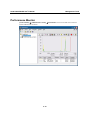
Performance Monitor
[Control Panel] Æ [Administrative Tools] Æ Performance. You can use this tool to monitor
system and network resources.
3-13
V2401/2402 WinXP User’s Manual
Management Tools
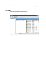
Services
[Control Panel] Æ [Administrative Tools] Æ Services
You can use this utility to start/stop/restart services.
(e.g. If you do not need telnet service you can stop it and set the “startup option” to “manual”.)
3-14
4
Chapter 4
System Recovery
The V2401/2402-XPE ready-to-run embedded computers are a Windows Embedded Standard
2009 platform. This chapter describes the recovery process in the event of system instability.
The following topics are covered in this chapter:
Recovery Environment
Recovery Procedure
V2401/2402 WinXP User’s Manual
System Recovery
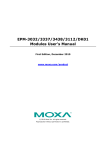
Recovery Environment
The environment includes a V2401/2402-XPE embedded computer and a bootable USB disk with
the recovery programs and system image file.
Hardware
The hardware used includes a PC, a V2401/2402-XPE computer and a USB disk with the recovery
programs. (Note: The USB disk should be at least 2GB.).
V2401/2402-XPE
USB DISK
(Recovery data included)
USB Ports
Recovery Procedure
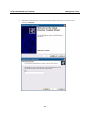
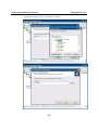
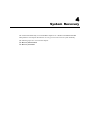
Step 1: Install XPE Disk Recovery
Insert the software CD (in your package) into your computer and find XPeRecovery.msi in the
recovery folder. Double-click XPeRecovery.msi to start the setup process and click Next.
4-2
V2401/2402 WinXP User’s Manual
System Recovery
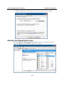
Click Browse and select the folder you wish to install to and then click Next.
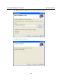
Click Next to start the installation.
4-3
V2401/2402 WinXP User’s Manual
System Recovery
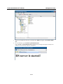
Click Close to finish.
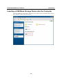
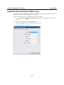
Step 2: Extract Recovery Image from PC to USB disk
After the installation is complete, you will see the XPeRecovery shortcut on your desktop. You
can start the USB disk recovery utility by opening this shortcut. Double-click the shortcut then
click OPEN to select the image file. This file is located on the software CD in the recovery folder,
and the filename is V2400_V1.0_Build_yymmddhh.wim. You may also copy this file to your PC.
In the following example, we have already copied the image file to the D drive of the PC.
4-4
V2401/2402 WinXP User’s Manual
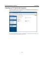
System Recovery
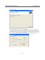
Click the drop-down list and select your USB disk drive letter (in this example, it is the E drive),
and check Format USB Disk.
4-5
V2401/2402 WinXP User’s Manual
System Recovery
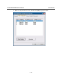
Click Apply to start the process; the utility will display the progress and time remaining
This message will appear when the process is complete. Click OK.
4-6
V2401/2402 WinXP User’s Manual
System Recovery
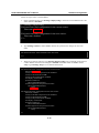
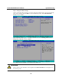
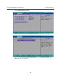
Step 3: Change the BIOS Settings
On the V2401/2402-XPE computer, you need to change the BIOS settings to boot from USB disk.
Turn on the computer and press DEL to enter the BIOS setup menu. Select Hard Disk Boot
Priority and press Enter.
Select USB disk and then press “+” to make it the first boot device. Warning: Incorrect boot
disk priority will lead to recovery failure.
Press F10 and then press Enter to save and leave the BIOS setup.
ATTENTION
Please note that some USB disks will be regarded as the Removable Device. If it happens, see
the following steps.
4-7
V2401/2402 WinXP User’s Manual
a.
System Recovery
Select Removable Device Priority.
b. Make sure that the USB disk has been detected. Press Esc to exit.
c.
Make sure that the First Boot Device is Removable. If not, select First Boot Device, press
Enter and select it from the list.
4-8
V2401/2402 WinXP User’s Manual
System Recovery
d. Select Exit Æ Save & Exit Setup and then press Enter.
e.
Choose Y to save to the CMOS and then exit.
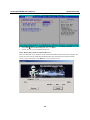
Step 4: Reboot the Computer and Start Recovery
Insert the USB disk on any USB port of the V2401/2402-XPE, and then reboot the computer. The
system will boot from the USB disk and the Windows Pre-installation Environment and the
recovery utility will appear. Click Recover to start system recovery.
4-9
V2401/2402 WinXP User’s Manual
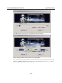
System Recovery
Click OK when the recovery process is complete and system will reboot.
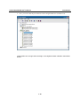
Step 5: Change the BIOS Setting to Boot from Original Disk.
Now, you need to change the boot priority so that it can boot from the original disk. As the system
reboots, press DEL to enter BIOS setup menu. Select Hard Disk Boot Priority and press Enter.
Make sure that the hard disk has first boot priority.
4-10
V2401/2402 WinXP User’s Manual
System Recovery
Press F10 and then press Enter to save and leave the BIOS settings.
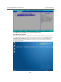
Step 6: Reboot the Computer.
Remove the USB disk from the USB port before restarting and rebooting the V2401/2402-XPE.
You need to wait for about ten to fifteen minutes while the system recovers. DO NOT power off
or shut down the computer during this time or the IIS service will be terminated. When the
operating system has successfully launched, you need to restart your computer so that the new
settings can be activated.
4-11