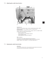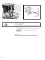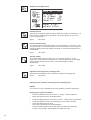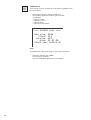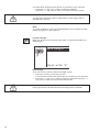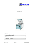
1
511 CNC-Automat für Riegel- und Kurznähte CNC automat for bartacking seams and short seams Bedienanleitung / Operating Instructions 1 Aufstellanleitung / Installation Instructions 2 Serviceanleitung / Service Instructions 3 Postfach 17 03 51, D-33703 Bielefeld Potsdamer Straße 190, D-33719 Bielefeld Telefon +49 (0) 5 21/ 9 25-00 Telefax +49 (0) 5 21/ 9 25 24 35 www.duerkopp-adler.com Ausgabe / Edition: 08/2009 Änderungsindex Rev. index: 00.0 Printed in Federal Republic of Germany Teile-Nr./Part.-No.: 0791 511001 Alle Rechte vorbehalten. Eigentum der Dürkopp Adler AG und urheberrechtlich geschützt. Jede, auch auszugsweise Wiederverwendung dieser Inhalte ist ohne vorheriges schriftliches Einverständnis der Dürkopp Adler AG verboten. All rights reserved. Property of Dürkopp Adler AG and copyrighted. Reproduction or publication of the content in any manner, even in extracts, without prior written permission of Dürkopp Adler AG, is prohibited. Copyright © Dürkopp Adler AG - 2009 Foreword This instruction manual is intended to help the user to become familiar with the machine and take advantage of its application possibilities in accordance with the recommendations. The instruction manual contains important information on how to operate the machine securely, properly and economically. Observation of the instructions eliminates danger, reduces costs for repair and down-times, and increases the reliability and life of the machine. The instruction manual is intended to complement existing national accident prevention and environment protection regulations. The instruction manual must always be available at the machine/sewing unit. The instruction manual must be read and applied by any person that is authorized to work on the machine/sewing unit. This means: – – – Operation, including equipping, troubleshooting during the work cycle, removing of fabric waste, Service (maintenance, inspection, repair) and/or Transport. The user also has to assure that only authorized personnel work on the machine. The user is obliged to check the machine at least once per shift for apparent damages and to immediatly report any changes (including the performance in service), which impair the safety. The user company must ensure that the machine is only operated in perfect working order. Never remove or disable any safety devices. If safety devices need to be removed for equipping, repairing or maintaining, the safety devices must be remounted directly after completion of the maintenance and repair work. Unauthorized modification of the machine rules out liability of the manufacturer for damage resulting from this. Observe all safety and danger recommendations on the machine/unit! The yellow-and-black striped surfaces designate permanend danger areas, eg danger of squashing, cutting, shearing or collision. Besides the recommendations in this instruction manual also observe the general safety and accident prevention regulations! General safety instructions The non-observance of the following safety instructions can cause bodily injuries or damages to the machine. 1. The machine must only be commissioned in full knowledge of the instruction book and operated by persons with appropriate training. 2. Before putting into service also read the safety rules and instructions of the motor supplier. 3. The machine must be used only for the purpose intended. Use of the machine without the safety devices is not permitted. Observe all the relevant safety regulations. 4. When gauge parts are exchanged (e.g. needle, presser foot, needle plate, feed dog and bobbin) when threading, when the workplace is left, and during service work, the machine must be disconnected from the mains by switching off the master switch or disconnecting the mains plug. 5. Daily servicing work must be carried out only by appropriately trained persons. 6. Repairs, conversion and special maintenance work must only be carried out by technicians or persons with appropriate training. 7. For service or repair work on pneumatic systems, disconnect the machine from the compressed air supply system (max. 7-10 bar). Before disconnecting, reduce the pressure of the maintenance unit. Exceptions to this are only adjustments and functions checks made by appropriately trained technicians. 8. Work on the electrical equipment must be carried out only by electricians or appropriately trained persons. 9. Work on parts and systems under electric current is not permitted, except as specified in regulations DIN VDE 0105. 10. Conversion or changes to the machine must be authorized by us and made only in adherence to all safety regulations. 11. For repairs, only replacement parts approved by us must be used. 12. Commissioning of the sewing head is prohibited until such time as the entire sewing unit is found to comply with EC directives. 13. The line cord should be equipped with a country-specific mains plug. This work must be carried out by appropriately trained technicians (see paragraph 8). It is absolutely necessary to respect the safety instructions marked by these signs. Danger of bodily injuries ! Please note also the general safety instructions. Contents Page: Preface and General Safety Instructions Part 1: Operating Instructions for Class 511 (Edition 08/2009) 1. Product Description . . . . . . . . . . . . . . . . . . . . . . . . . . . . . . . . . . . . . . . . . . . 3 2. Proper and Intended Use . . . . . . . . . . . . . . . . . . . . . . . . . . . . . . . . . . . . . . . . 4 3. Sub-classes . . . . . . . . . . . . . . . . . . . . . . . . . . . . . . . . . . . . . . . . . . . . . . . . . 5 4. Additional Equipment . . . . . . . . . . . . . . . . . . . . . . . . . . . . . . . . . . . . . . . . . . 5 5. Frame . . . . . . . . . . . . . . . . . . . . . . . . . . . . . . . . . . . . . . . . . . . . . . . . . . . . . 6 6. 6.1 Technical Specifications . . . . . . . . . . . . . . . . . . . . . . . . . . . . . . . . . . . . . . . . . Sub-class-specific technical parameters . . . . . . . . . . . . . . . . . . . . . . . . . . . . . . . . 6 7 7. 7.1 7.2 7.3 7.4 7.5 7.6 7.7 7.8 Operations Threading the needle thread . . . . . Adjusting the needle thread tension . Opening the needle thread tension . Adjusting the thread regulator . . . . Winding the bobbin thread . . . . . . Replacing the shuttle bobbin . . . . . Adjusting the bobbin thread tension . Replacing the needle . . . . . . . . . . 8. 8.1 8.1.1 8.2 8.2.1 8.3 8.3.1 8.3.2 8.3.3 8.4 8.5 Operating the 511 Controller The control panel . . . . . . . . . . The keys . . . . . . . . . . . . . . . User interface . . . . . . . . . . . . Structure of menu . . . . . . . . . . Alter numerical values, parameter Alter numerical values . . . . . . . Selection of a parameter . . . . . . Selection of alternatives . . . . . . Seam pattern . . . . . . . . . . . . Power saving mode . . . . . . . . . . . . . . . . . . . . . . . . . . . . . . . . . . . . . . . . . . . . . . . . . . . . . values, . . . . . . . . . . . . . . . . . . . . . . . . . . . . . . . . . . . . . . . . . . . . . . . . . . . . . . . . . . . . . . . . . . . . . . . . . . . . . . . . . . . . . . . . . . . . . . . . . selection . . . . . . . . . . . . . . . . . . . . . . . . . . . . . . . . . . . . . . . . . . . . . . . . . . . . . . . . . . . . . . . . . . . . . . . . . . . . . . . . . . . . . . . . . . . . . . . . . . . . . . . . . . . . . . . . . . . . . . . . . . . . . . . . . . . . . . . . . . . . . . . . . . . . . . . . . . . . . . . . . . . . . . . . . . . . . . . . . . . . . . . . . . . . . . . . . . . . . . . . . . . . . . . . . . . . . . . . . . . . . . . . . . . . . . 8 9 9 10 11 12 13 14 . . . . . . . . . . . . . . . . . . . . . . . . . . . . . . . . . . . . of alternatives . . . . . . . . . . . . . . . . . . . . . . . . . . . . . . . . . . . . . . . . . . . . . . . . . . . . . . . . . . . . . . . . . . . . . . . . . . . . . . . . . . . . . . . . . . . . . . . . . . . . . . . . . . . . . . . . . . . . . . . . . . . . . . . . . . . . . . . . . . . . . . . . . . . . . . . . . . . . . . . . . . . . . . . . . . . . . . . . . . . . . . . . . . . . . . . . . . . . . . . . . . . . . 15 15 17 17 18 18 19 19 20 20 1 Contents Page: 8.6 8.6.1 8.6.2 8.6.3 8.6.3.1 8.6.3.2 8.6.4 8.7 8.8 8.8.1 8.8.2 8.8.3 Main menu . . . . . . . . . . . . . . . . . . . . . . . . Seam pattern operation . . . . . . . . . . . . . . . . Programming mode . . . . . . . . . . . . . . . . . . . Seam pattern sequences . . . . . . . . . . . . . . . Switching the sequence programming mode on or Programming a sequence . . . . . . . . . . . . . . . Technician mode . . . . . . . . . . . . . . . . . . . . Distributor PCB . . . . . . . . . . . . . . . . . . . . . Error messages . . . . . . . . . . . . . . . . . . . . . Error categories . . . . . . . . . . . . . . . . . . . . . Application messages . . . . . . . . . . . . . . . . . Machine faults (DACIII) . . . . . . . . . . . . . . . . . . . . . . . . off . . . . . . . . . . . . . . . . . . . . . . . . . . . . . . . . . . . . . . . . . . . . . . . . . . . . . . . . . . . . . . . . . . . . . . . . . . . . . . . . . . . . . . . . . . . . . . . . . . . . . . . . . . . . . . . . . . . . . . . . . . . . . . . . . . . . . . . . . . . . . . . . . . . . . . . . . . . . . . . . . . . . . . . . . . . . . . . . . . . . . . . . . . . . . . . . . . . . . . . . . . . . . . . . . . . . . . . . . . . . . . . . . . . . . . . . . . . . . . . . . . . . . . . . . . . . . . . . . . . . . . . . . . . . . . . . . . . . . . . . . . . . . . . . . . . . . . . . . . . . . . 21 21 26 30 30 33 34 78 80 80 81 83 9. Sewing . . . . . . . . . . . . . . . . . . . . . . . . . . . . . . . . . . . . . . . . . . . . . . . . . . . . 87 10. 10.1 10.2 Maintenance Cleaning and checking . . . . . . . . . . . . . . . . . . . . . . . . . . . . . . . . . . . . . . . . . . . Oil lubrication . . . . . . . . . . . . . . . . . . . . . . . . . . . . . . . . . . . . . . . . . . . . . . . . 88 89 11. Standard Seam Patterns . . . . . . . . . . . . . . . . . . . . . . . . . . . . . . . . . . . . . . . . . 90 12. Clamping Feet . . . . . . . . . . . . . . . . . . . . . . . . . . . . . . . . . . . . . . . . . . . . . . . 97 1. Product Description The Dürkopp Adler 511 is a CNC machine for bartacking seams and short seams. The available standard bartacks are size-adjustable and can additionally be saved in this modified shape. Free seam contours can be programmed directly at the control panel without any further devices. Technical features – DAC control unit with control panel. The following functions are available: – 50 standard bartacks. These bartacks can temporarily be modified in respect to length, width and speed. When switching off the machine, the modified values of the bartack last sewn are maintained. – 40 modified bartacks can also be saved. – 9 free seam contours with a total of 5000 available stitches can also be saved. So it is possible to attach small appliqués. The coordinates are entered at the control panel. No further devices are required. – 25 seam pattern sequence programs with up to 20 seam patterns per seam pattern sequence program can be created and saved. – The coordinates are entered with a precision of 0.1 mm. – If there is a rectangular contour of the fabric clamping feet, the modification of bartacks is automatically checked in order to avoid a collision of needle and fabric clamping feet. – Counters are available for capacity and daily number of pieces. – Bartacks and seam pattern sequence programs and the modification of special bartacks can be blocked. – The speed can be changed from 0 rpm (manual operation with full operability of the x-y drive) up to 2700 rpm in steps of 100 rpm. – Fabric drive via two step motors. – Drive of the automatic bartacker directly at the arm shaft via brushless direct current motor. – Maximum sewing field size 40 x 20 mm. – Oil wick lubrication of arm shaft and driving shaft with two oil reservoirs. – Service and maintenance work is supported by a comprehensive test programs. 3 1 2. Proper and Intended Use The class 511 machine is a bartacking machine designed for sewing light to medium-heavy material. Such material is generally made of textile fibres, but it may also be leather. Such fabrics are used in the clothing industry and for domestic and motor-vehicle upholstery. Furthermore, this automatic bartacker can also sew “technical” seams. In such a case, the operator must assess the possible dangers which may arise (preferably in conjunction with DÜRKOPP ADLER AG). Such applications are relatively unusual and also so varied that no single set of criteria can cover them all. You may need to take appropriate safety measures based on the outcome of this assessment. Generally, only dry fabrics can be processed on this automatic bartacker. The material may be no thicker than 10 mm when compressed by the lowered sewing feet. The material should not contain any hard objects. If hard objects are present, the machine must be operated with protective eye wear. We currently do not provide such eye protection. In general the seam is produced with sewing threads made of textile fibres (cotton threads, synthetic threads or core threads) with the following dimensions: Class 511-211/212 threads of the dimension 50/3 - 120/3 Class 511-213/214 threads of the dimension 30/3 - 120/3 If other threads are to be used, it is important to consider the possible risks and to take corresponding safety measures. This automatic bartacker must only be installed and operated in dry and well-kept rooms. If it is operated in other spaces which are not dry and well-kept, further measures may need to be agreed upon (see EN 60204-31: 1999). As manufacturers of industrial sewing machines, we proceed on the assumption that personnel who work on our products will have received training at least sufficient to acquaint them with all normal operations and with any hazards which these may involve. 4 3. Sub-classes Class 511-211 Automatic single-needle lockstitch bartacker with thread trimmer and thread wiper. Equipped with special sewing equipment for general bartacking operations in outer garments. With electro-magnetic sewing foot lift. Class 511-212 Automatic single-needle lockstitch bartacker with thread trimmer and thread wiper. Equipped with a contraction clamp specially for bartacking double-chainstitch buttonholes. With electro-magnetic sewing foot lift. Class 511-213 Automatic single-needle lockstitch bartacker with thread trimmer and thread wiper. Equipped with special sewing equipment for particularly thick fabrics. Field of application: General bartacking operations, e.g. bartacking of loops, pockets or fly pieces in jeans or working clothes. With electro-magnetic sewing foot lift. Automatic single-needle lockstitch bartacker with thread trimmer and thread wiper. Equipped with a special sewing equipment for particularly thick fabrics. Field of application: General bartacking operations, e.g. bartacking of loops, pockets or fly pieces in jeans or working clothes. With electro-magnetic sewing foot lift. Class 511-213 4. Additional Equipment The following optional equipment is available for the automatic bartacker 510: Order no. Optional equipment Refer to Parts List Special clamping foot set (optional/special manufacture, APC) 0510 59 015 4 Electric thread wiper (511-211, -213, -214) 0510 59 006 4 Pneumatic sewing foot lifting (511-211, -213, -214) 0510 59 012 4 Separate pneumatic sewing foot lift (pneum. control unit) and sewing foot lift arm are on right and left (511-211, -212, -213, -214). 9780 00 010 8 Maintenance unit 0510 59 009 4 Conversion set for -211 to -213 0510 15 001 4 Large capacity hook; conversion kit for classes (511-211, -212, -213) 0510 59 004 4 Laser marking light (3 lights) 0510 59 003 4 Additional laser light 0510 59 005 4 Hand switch 9822 51 002 6 Sewing light 9822 51 002 7 Table clamp 9870 00 102 1 Cable assembly K (add-on kit socket for sewing light) 5 1 5. Frame The following stand is available for the automatic bartacker 511: MG55 40 029 4 Stand package Table top size 600 x 1060 mm Stand height 1160 to 1305 mm MG53 40 148 4 Stand package (China) Table top size 600 x 1060 mm Stand height 1160 to 1305 mm 6. Technical Specifications Noise level: Lc = 78dB (A) Workplace-related emission value according to DIN 45635-48-A-1-KL-2: Bartack length: Stitch/bartack: Throw width: Speed: Fabric: Sewing cycle: 6 15 mm 28 2.5 mm 2700 min -1 G1 DIN 23328 two-ply 1.3 sec on and 1.0 sec off 6.1 Sub-class-specific technical parameters Sub-class: -211 -212 -213 -214 Stitch type: 301 301 301 301 Hook type: oscillating hook Needle system: DPx5 (134) Needle size: [Nm] Needle size standard production: [Nm] Thread size: Stitch length: Max. speed 90 DPx17 (135x17) 90 50/3 - 120/3 [mm] [min -1 ] Clamp stroke Delivery maximum [mm] Sewing field size Max. in X-direction: Max. in Y-direction: [mm] 120 50/3 - 120/3 30/3 - 120/3 dependent on seam pattern 2700 13 17 1 40 20 Number of standard bartacks 50 Number of storable modifiable bartacks 40 Number of seam-pattern sequence programs 25 Number of seam patterns per seam-pattern sequence program 20 Soft start: connectable / dis-connectable Operating pressure: [bar] 6 Air consumption: [NL] 3 Sewing drive: Rated voltage: 120 DC motor [V] 1 ~ 230V/ 50/60 Hz Rated load: [kW] 0.45 Length, width, height [mm] 730 / 1060/ 1160 - 1305 Weight [kg] 125 7 7. Operations 7.1 Threading the needle thread Caution – Risk of Injury ! Turn the main switch off! Insert the needle thread only when the automatic bartacker is switched off. – – 8 Put thread reels on the thread reel holder and insert needle thread and bobbin thread through the unwinding arm. The unwind holder must be perpendicular to the reel. Thread the needle thread as shown on the following illustration. 7.2 Adjusting the needle thread tension 1 3 2 1 Pretension 3 With the main tension 2 open, a minor residual stress of the needle thread is required. This residual tension is created by the pre-tensioner 3. The pre-tensioner 3 influences both the length of the cut needle thread and the starter thread for the next seam. – Shorter starter thread: Turn knurled nut 1 in clockwise direction. – Longer starter thread: Turn knurled nut 1 counter-clockwise. Main tension 2 The control unit is used to adjust the main tension 2. A maximum of five thread tension ranges can exist for one seam pattern. (Refer to the chapter on “Controller Operations”.) 7.3 Opening the needle thread tension Automatic The needle thread tension is automatically opened when trimming the thread and when lifting the fabric clamping feet. 9 7.4 Adjusting the thread regulator 3 2 1 Caution – Risk of Injury ! Turn the main switch off. Adjust thread regulator only when the automatic bartacker is switched off. The thread regulator 3 is used to control the quantity of needle thread required by the stitch formation. The best sewing results can only be ensured when using a precisely adjusted thread regulator. At the properly adjusted setting, the needle thread loop must be able to slide over the thickest section of the hook. – Loosen screw 1. – Change the position of the thread regulator 3. Thread regulator to the left = more thread. Thread regulator to the right = less thread. – Tighten screw 1. Settings note: If the largest thread quantity is required, the thread controller spring 2 must be pulled down by approx. 0.5 mm from its upper end position. This occurs when the needle thread loop passes the section of the hook with the widest diameter. 10 7.5 Winding the bobbin thread 5 1 4 3 2 6 – – – – – – Put bobbin on bobbin winder 4. Pull thread through guide 2 and around tension 1. Wind thread counter-clockwise around the core of the bobbin (approx. 5 times). Press the bobbin-winder lever 3 in the bobbin. Sew. The winder lever stops as soon as the bobbin is full. Tear off thread at thread clamp 5 after winding up is finished. 1 Note! If the thread is to be wound on without sewing, the thread winding mode can be altered in sub-menu “Special functions”. : Off : : On ... If the thread winding mode is active, the sewing motor can be started via pedal or push button independent of the sewing field drive (unthread at the thread lever). For adjustment, see chapter 8.5.1 “Thread winding mode”. 11 7.6 Replacing the shuttle bobbin 1 7 4 2 5 6 2 3 Caution – Risk of Injury ! Turn the main switch off. Change hook thread bobbin only when automatic bartacker is switched off. Taking off the empty bobbin – Pull down hook cover 3. – Raise up the bobbin enclosure hood 1. – Take out the upper part of the bobbin enclosure 2 with the bobbin 6. – Remove the empty bobbin from the upper part of the bobbin enclosure 2. Inserting a full bobbin – Place full bobbin in the top of bobbin case 2. – Thread bobbin thread through slot 5 below tension spring 7 in the drill-hole 4. – Pull out the tension spring from the bobbin enclosure 2 about 2.5 cm. When the thread is being pulled out, the bobbin must rotate in the direction shown by the arrow. – Replace bobbin housing 2. – Close bobbin enclosure hood 3. 12 7.7 Adjusting the bobbin thread tension 1 2 3 1 Caution – Risk of Injury ! Turn the main switch off. Adjust the bobbin thread tension only when the automatic bartacker is switched off. The required bobbin thread tension should be generated by tension spring 1. The top of bobbin case 3 should drop slowly due to its own weight when being held at the threaded-in bobbin thread. Setting the tension spring – Take off top of bobbin case 3 with the bobbin. – Adjust tension spring 1 at the regulating screw 2 until the required tension value is reached. – Reinsert top of the bobbin case. 13 7.8 Replacing the needle 2 1 3 2 1 Caution – Risk of Injury ! Turn the main switch off. Change the needle only when the automatic bartacker is switched off. – – – Loosen screw 1. Push in the new needle until it reaches the limit stop in the hole for the needle bar 2. CAUTION ! The hollow groove 3 of the needle must point to the hook. Tighten screw 1. CAUTION ! After the changeover to another needle size, the distance between hook and needle has to be corrected (see service instructions). 14 8. Operating the 511 Controller 8.1 The control panel A control panel with an LCD display and function keys is used for input and output of data. 1 8.1.1 The keys Function key Function Cursor keys If no text field is activated: Press the “ï” key to return from a sub-menu to the parent menu. If a text field is activated: Change between the points (this does not refer to the selection of seam patterns or sequences). In the sewing mode during sequence operation: Change to the next or to the preceding seam pattern. 15 Function key Function If no text field is activated: Change between the lines of the menus. The selected line is displayed white on black. If a text field is activated: Increase or reduce the value of the respective point by one, or change between the parameters in the event that there are functions with several choices. OK key If no text field is activated: Activate the text field. The value can be altered with the “ñ” and “ò” keys. If a text field is activated: The set value is applied. If the clamping foot has been lowered using the keys OK + F: The test procedure will be started. ESC key If test functions are activated (Multitest / 180° disc): You return to the selection menu. If a text field is activated: An input will be aborted. The preceding value is maintained. In the technician and programming level The control changes over to the sewing mode. In the sewing mode: Lift clamping foot and stop sewing operation. P key The control unit changes over from the sewing mode to the programming mode. In this mode, altered stitch patterns can be saved under a new program number. S key The control unit changes over from the sewing mode or seam pattern programming mode to the sequence programming mode. In this mode it is possible to create new sequences or to alter existing ones. F key The control changes over from the sewing mode to the technician mode. This mode can only be activated after a code has been entered. In this operating status it is possible to set basic machine parameters and to retrieve diagnostic and adjustment programs. 16 8.2 8.2.1 User interface Structure of menu Turn on main switch F key Service menu Code 1 Sewing mode ESC key ESC key F key Code 1 P key Programming mode Key ESC 1 Technician mode S key S key P key Sequence programming mode Call up the service mode – Press the function key “F” and keep it pressed. – Turn on the main switch. The control unit is initialized. After a short while, the window for entering the code number will appear. – Enter the code number (code 1, refer to chapter 8.5.4). The display changes to the service menu. 17 Call up the technician mode – Turn on the main switch. The control unit is initialized. The sewing mode menu appears on the display. 8.3 8.3.1 – Press the “F” key. – Enter Code 1 (see Chapter 8.5.4). – – Press the “OK” key. The display changes over to the technician mode. Altering numerical values, parameter values and selection of alternatives Alter numerical values – Select the desired line with the “ñ” and “ò” keys. – Press the “OK” key. The chosen numerical value is marked by a blinking cursor. – Change between the points with the “ï” or “ð” keys. Increase or reduce the value of the selected point by one with the “ñ” and “ò” keys. – Press the “OK” key. The currently set value is applied. or – Press the “ESC” key. The original value is maintained. Note All values can only be altered within the range of minimum and maximum values. 18 8.3.2 Selection of a parameter Some parameters offer a selection of non-modifiable adjustments. – Select the desired line with the parameter to be altered with the “ñ” and “ò” keys. – Press the “OK” key. – Change between the given possibilities with the “ñ” and “ò” keys. For example: Seam pattern number – Press the “OK” key. The currently set parameter is applied. 1 Or – Press the “ESC” key. The original parameter is maintained. 8.3.3 Selection of alternatives Some menu items can be selected alternatively. The current selection is marked with a checkmark (...ü). If another alternative is selected, the marking of the current choice is removed and the new menu item is marked. Alternatively selectable items are set off against other menu items by a separating line. 19 8.4 Seam pattern Three different seam pattern types are available for the automatic bartacker 511: · Specified standard seam patterns (Type 1) (see chapter 11): The sewing parameters length, width and sewing speed can be altered in the sewing mode; the laser marking lamps can be switched on and off. The alterations are saved. However, after selection of another seam pattern, the alterations will be lost. For these seam patterns the seam pattern numbers 1 to 50 are available and cannot be deleted or overwritten. · Programmable seam patterns (Type 2) Specified standard seam patterns can be altered in the programming level (length, width, sewing speed, laser light 1 to 8) and saved under a new program number. For these seam patterns, the seam pattern numbers 51 to 90 are available and can be deleted or overwritten. · Free seam contours (Type 3): For these seam contours, the seam patterns numbers 91 to 99 are available. The creation of free seam contours is described in chapter 8.5.4.4. The sewing parameters length, width and sewing speed can be altered in the sewing mode; the laser marking lamps can be switched on and off. The alterations are saved. However, after selection of another seam pattern, the alterations will be lost. 8.5 Power saving mode Power saving mode is activated after an adjustable interval (1 – 60 min) by using t5 in the Machine Configuration/Times menu. Power saving mode can be deactivated by setting t5 to 0. The clamping foot descends when it is activated in order to save power. This also reduces the generation of heat. The defined time elapses when there is no user input is carried out on the control panel, pedal or hand switch. Before the power saving mode activates, a message indicating that the clamping foot will descend flashes twice as an alert. After that, the message stays on the screen. As soon as a user operates the control panel, pedal or hand switch, the normal mode of operations is resumed. The clamping foot is then raised and the message is no longer displayed. The machine is now ready for use. 20 8.6 8.6.1 Main menu Seam pattern operations The parameters for the individual seam patterns are found in the main menu. The seam patterns can be altered using these parameters. – Turn on the main switch. The control unit is initialized. The main menu appears. – Select the desired parameter with the “ñ” and “ò” keys. The symbol of the selected parameter is displayed white on black. Alter selected parameter as described in chapter 8.3. – 1 Menu option The symbol in the top left corner of the display describes the currently selected menu item. Bartack pattern The symbol at the bottom left of the display shows the current bartack pattern. Seam pattern This parameter is used to select the seam pattern to be sewn. Selection: 1 – 51 (52 to 99 if available) Speed The desired speed is set using this parameter. Input: 0 to 2700 rpm 21 Thread tension in range 1 (refer to table 1) Input: 0 – 100 0 = lowest thread tension 100 = highest thread tension The thread tension magnet adjusts the thread tension according to the current value so that it can then be checked. The thread tension values for all further ranges in the seam pattern are set as the difference to the previous value. For the standard seam patterns (1 – 50), the thread tension cannot be individually set for the different ranges. If this is required, then a seam pattern program must be created. Sub-menu for seam pattern size and offset Select this sub-menu to set the seam pattern length and width. Display: current length/width Width Setting the seam pattern width Input: 0.1 – 40 [mm] Length Setting the seam pattern length Input: 0.1 – 20 [mm] X Offset Setting the seam pattern offset in the X-direction. Input: -20.0 – +20.0 Y Offset Setting the seam pattern offset in the Y-direction. Input: -10.0 – +10.0 When switching to this menu, the clamping foot will be lowered. If the value for the X- and Y-Offset is changed, the stepping motors will move the material accordingly. When exiting the sub-menu, the clamping foot will then be raised again. Caution – Risk of Injury ! Do not reach into the working area of the machine while you are in this sub-menu and performing changes on the seam pattern offset. 22 Number of stitches The number of stitches is indicated on this menu line (it cannot be modified). When selecting the line with the “OK” key, the sub-menu “Special functions” is opened. When selecting the line with the “OK” key, the sub-menu “Counter of daily number of pieces/Counter of capacity” is opened. Reset counter for daily number of pieces – Select the menu item by using the “ñ” and “ò” keys. – Press the “OK” key for 3 seconds until the displayed piece count is reset to 0. The daily piece count can be reset in this way. However when the capacity status is displayed, the value cannot be reset to 0 in this way. or Capacity counter 1 When selecting the line with the “OK” key, the sub-menu “Counter of daily number of pieces/Counter of capacity” is opened. Sub-menu “Special function and soft start status” Thread winding mode The bobbin thread winder can be operated separately. At the setting “ON”, the sewing motor can be started independent of the step motors using the pedal or key. Input: ON / OFF 23 Winding thread onto a bobbin: With the pedal: – Step pedal forwards (step 2). The sewing motor starts. – Step pedal backwards. The sewing motor stops. With the control panel – Press the “F” key. The sewing motor starts. – Press the “ESC” key. The sewing motor stops. With push button (optional) – Press button 2. The sewing motor starts. – Press button 1. The sewing motor stops. Soft start The soft start can be switched on or off using this parameter. Input: ON / OFF Sub-menu laser marking light (optional) This menu item is only available when the laser light option in the Configuration menu is activated. Laser light 1 – 3 Switching on/off for the laser marking light 1 to 3. Input: ON / OFF 24 Sub-menu for counter of daily number of pieces or counter of capacity S .......Ö (5000) -: S =?: On 5000 Alternative display of counter of daily number of pieces or counter of capacity. Both counters work in parallel. You can select which counter is displayed in the main menu. · · – The counter of the daily number of pieces counts the number of the sewn seam patterns Display: 0 – 65000 The bobbin thread counter counts backwards. When the value “0" is reached and a sewing operation is started, a message is shown. Display: 9999 – 0 Press the “ESC” key. Back to the main menu. If the daily piece counter is set, the following display appears: Displaying the daily piece in sewing mode: Input: Select using the “OK” key Displaying the counter of capacity in sewing mode: Input: Select using the “OK” key Counter of capacity ON/OFF Input: ON/OFF Initial value counter of capacity Input: 0 ... 9999 25 1 8.6.2 Programming mode Under this menu item, the parameters for programming of seam patterns are arranged. With the help of these parameters, the shape, length, width and speed of the seam pattern are specified. : : : : : : : : 51 1 2700 25 16.0/ 2.0 0.0/ 0.0 42 On – Turn on the main switch. The control unit is initialized. The main menu appears. – Press function key “P” on the main menu. The display changes over to the menu of the programming mode. – Select the desired parameter with the “ñ” and “ò” keys. The symbol of the selected parameter is displayed white on black. Alter the selected parameter as described in chapter 8.3. – Number of seam pattern The number of the seam pattern to be created or altered is selected using this parameter. When preparing a new program, an asterisk (*) is indicated before the number. Input: 51 90 – Select the desired seam pattern program with the “ñ” and “ò” keys. – Press the “OK” key. The program is activated. Basic seam pattern Using this parameter, a standard seam pattern can be selected on the basis of which the new seam pattern is to be created. Input: 1 50 or 91 99 if available Sewing speed Using this parameter, the desired sewing speed can be adjusted. Input: 26 0 – 2700 [rpm] Sub-menu for thread tension The thread tension values for the ranges in the current seam pattern are specified here. Sub-menu for thread tension: cross-tack seam pattern. Thread tension in Thread tension in Thread tension in The thread tension sub-menu for the range 1 (linear thread tension) range 2 (zig-zag thread tension) range 5 (thread tension at seam end) 1 Input: 0 100 , 0 = lowest thread tension 100 = highest thread tension All values can be set independently from each other. The adjustable tension values for all additional standard seam patterns can be taken from the following table. A maximum of five thread tension ranges can exist for one seam pattern. At the programming level, another tension value can be specified for each range. The ranges are defined internally for the standard seam pattern. They can be programmed as desired for the free seam contours. The first tension range (1) is available for all types of seam patterns and also for the free seam contours. The thread tension can be distinctly adjusted in the individual ranges only when working with the seam pattern programs. For standard seam patters, only the thread tension in the first range can be set. The other ranges are then changed accordingly. 27 Seam pattern Tack type Cross tack Straight-lined cross tack Longitudinal tack Straight-lined longitudinal tack Circular tack, stitched eyelet D tack Imitated button-hole tack Circular tack Tri-tack No. 1 - 16 17 - 22 23 - 26 27 - 30 31 - 34 35 - 44 45 - 46 47 - 48 49 - 50 Thread tension Range Description 1 Linear thread tension 2 Zig-zag thread tension 5 Seam-end thread tension 1 Linear thread tension 5 Seam-end thread tension 1 Linear thread tension 2 Zig-zag thread tension 5 Seam-end thread tension 1 Linear thread tension 5 Seam-end thread tension 1 Thread tension right 2 Thread tension left 3 Zig-zag thread tension (only stitched eyelet) 5 Seam-end thread tension 1 Linear thread tension 2 Half-circle thread tension 3 Zig-zag thread tension 5 Seam-end thread tension 1 Seam-end thread tension 2 Zig-zag thread tension 5 Seam-end thread tension 1 Thread tension up/down 2 Thread tension left diagonal 3 Thread tension right diagonal 5 Seam-end thread tension 1 Linear thread tension 2 Triangular thread tension 3 Zig-zag thread tension 5 Seam-end thread tension In the thread tension menu found on the seam-pattern programming level, the ranges are displayed in the menu bar and also as an icon at the bottom left. The range numbers are only displayed when working with a free seam contour or a seam-pattern program with a free seam contour as a base seam pattern. 28 Sub-menu for seam pattern dimension Select this sub-menu to set the seam pattern length and width. Display: current length/width Sub-menu for seam pattern offset Select this sub-menu to set the seam pattern offset in the X and Y directions. Display: current X/Y offset values Number of stitches Only indicates the number of stitches. Soft start The soft start can be switched on or off using this parameter. Input: ON / OFF First clamp (optional) With this menu item you can set which part of the clamping foot (left or right) will be lowered first. The menu item will only be displayed if the “lower clamping foot separately” option is activated in the Configuration menu. Input: ½ (left/right) Sub-menu for laser marking light (optional) This menu item will only be displayed if the option Laser light is activated in the Configuration menu. Laser lights 1 – 3 Switching on/off for the laser marking lights 1 to 3. Input: ON / OFF 29 1 8.6.3 Seam pattern sequences 8.6.3.1 Switching the sequence programming mode on or off Changeover from seam pattern operations to the seam pattern sequence operations – Press the function key “S” while the main menu is being displayed in order to go to the sequence programming mode. 0 – – Start the editing by pressing the “OK” key. Select any sequence by using the “ñ” key (1-25) – Confirm the selection with the “OK” key. The seam pattern sequence operation is switched on. – Press the “ESC” key or the “ï” key. The main menu for the seam pattern sequence operation will be displayed The sequence number and sequence items in the main menu will be described at the end of this section. 30 Switching from seam pattern sequence operation to seam pattern operation – Press the function key “S” while the main menu is being displayed in order to go to the sequence programming mode. – – Start the editing by pressing the “OK” key. Select the sequence number 0 by using the “ò “ key. – Confirm the selection with the “OK” key. The seam pattern sequence operation is switched off. – Press the “ESC” key or the “ï “ key. The main menu for the seam pattern operation will be displayed. 1 31 Menu items in the main menu for the seam pattern sequence Sequence Selection of the seam pattern sequence. Input: 1 (2 – 25, if available) Sequence succession Display of the sequence succession. The current seam pattern number is marked with a bar (underlined). If there are more than five numbers, the display is scrolled. Further seam patterns on the right: Further seam patterns on the left: Further seam patterns left and right: Automatic operations After the completion of a seam pattern, the control unit changes over to the next seam pattern shape automatically. After sewing of the last seam pattern, the control unit changes over to the first seam pattern within the sequence again. The current seam pattern is marked by a bar below the number. The shape of the selected seam pattern is indicated on the left half of the display. Manual operations The control unit does not change between the seam patterns automatically. – Select the next seam pattern with the “ï” or “ð” keys. The shape of the selected seam pattern is indicated on the left half of the display. Changing between automatic and manual operations – Select the second menu line with the “ñ” and “ò” keys (sequences) . – Press the “OK” key. – Select the mode of operation with the “ñ” and “ò” keys. For automatic operation, arrows are indicated between the seam patterns. Automatic operations Manual operations 32 8.6.3.2 Programming a sequence In this menu item, individual seam patterns are combined to form retrievable seam pattern sequences. A total of 25 independent seam pattern sequences are available. Every seam pattern sequence can be combined out of 20 seam patterns in any order. The seam pattern sequence operations can also be turned on in this menu. – Turn on the main switch. The control unit is initialized. The main menu appears. – Press function key “S” in the main menu. The display changes over to the menu of the sequence programming mode. – Select desired menu item with the “ñ” and “ò” keys. The menu line is displayed white on black. – Press the “ESC ” or “ï”key. Back to the main menu. 1 Sequence number/ seam pattern sequence operation Selection of the sequence to be created or to be altered. When preparing a new program, an asterisk (*) is indicated before the number. Input: 0 – 25 – Select the desired sequence number with the “ñ” and “ò” keys. If the seam pattern sequence operation should be switched off, select the sequence number 0. The menu line is displayed white on black. – Press the “OK” key. The program is activated. Seam pattern number (1 – 20) With this menu item, you can select the seam pattern number to be taken up in the current sequence. Input: 1 51 (52 – 99 if available) 33 8.6.4 Technician mode The following menus are included in the technician mode: Machine configuration In this menu, machine-specific adjustments are made. User configuration In this menu, operation-specific adjustments are made. Service functions These service functions allow a quick verification of all hardware components. Free contours With the automatic bartacker 510, up to nine freely-defined seam contours can be created and sewn. The coordinates are entered directly at the control panel. Memory dongle With the help of the memory dongle, data can be transferred from the machine to the dongle or vice versa. Cycle time This indicates the cycle time of the seam pattern last sewn (time from sewing start to sewing end). 34 Access technician mode – Turn on the main switch. The control unit is initialized. The main menu appears. – Press function key “F” in the main menu. The screen for the code entry appears. – Enter code number “25483“ (Code 1). After entry of the correct code number, the display changes over to the menu “Technician mode”. – Confirm with the “OK” key. The following menu appears: Machine User settings Service Free contours Memory dongle : ---- – Select the desired sub-menu with the “ñ” and “ò” keys. – Switch into the selected sub-menu with the “OK” key. 35 1 8.6.4.1 Machine configuration Parameter Soft start Equipment Times S : 262 Parameters In this sub-menu, different machine parameters can be set. Soft start In this sub-menu, the driving speeds for the soft start slope can be set. Equipment In this sub-menu, settings for the sewing equipment and optional units can be made. Times In this sub-menu, different timing parameters can be set. å 36 Machine cycles The total sewn cycles are displayed here. Sub-menu for machine parameters Cut.rpm: 250 Max.rpm: 2700 Stop pos.: 0 Sew.st.pt.: A Ref.freq.: 1 Cl.thr.cl.:160 Op.thr.cl.:300 Op.thr.tn.:300 – Select the desired parameter with the “ñ” and “ò” keys. The symbol of the selected parameter / sub-menu is displayed white on black. – Start selected parameter with the “OK” key or change into the sub-menu. 1 Cutting speed Input of the sewing motor speed in the last three stitches. Input: 100 – 600 [rpm] Maximum sewing speed Input of the maximum adjustable sewing speed Input: 2000 – 2700 [rpm] Stop position With the stop position, the positioning of the sewing motor / needle bar can be altered. Input: 0 = thin fabrics -15 = thicker fabrics Note The stop position is required for adjusting the corresponding material thickness. Chapter 8.3 “Changing the stop position” of the Installation Instructions includes a more detailed description for positioning the sewing motor. Loading position Selection of the material feeding position. Input: A = Seam start point B = Machine’s neutral position Note The following advantages or disadvantages can arise depending on the loading (feeding) position: Feeding point A = shorter cycle time Feeding point B = easier feeding of large seam patterns Seam patterns, longer cycle time 37 Referencing The referencing mode of the step motor after the sewing process can be configured in this menu item. Input: 0 = no referencing 1 = referencing each time 2 – 10 = referencing after each second to tenth sewing step Closed thread clamp angle Setting the angle for closing the thread clamp. Input: 100 ° 240° Opened thread clamp angle Setting the angle for opening the thread clamp. Input: Closed thread clamp ... 355° Opened thread tension angle Setting the angle for opening the thread tension in the last stitch. Input: 200° 355° The thread tension is opened before the thread-cut position is reached. Thus only the mechanical pre-tensioner is active during the cutting process. All angles are specified in relation to the reference position of the sewing motor. 38 Sub-menu for soft start In this sub-menu, speed adjustments for the soft start can be made. Speed first stitch Input of the speed in the first stitch. Input: 400 – 900 [rpm] Speed second stitch Input of the speed in the second stitch. Input: 1 400 – 2700 [rpm] Speed third stitch Input of the speed in the third stitch. Input: 400 – 2700 [rpm] Speed fourth stitch Input of the speed in the fourth stitch. Input: 400 – 2700 [rpm] Speed fifth stitch Input of the speed in the fifth stitch. Input: 400 – 2700 [rpm] 39 Sub-menu for sewing equipment In this sub-menu, adjustments for the sewing equipment can be made. W.clamp f....Ö Open dimens. Number: Length: Width: 1 4.5 20.0 Configuration Note The entry of the clamping foot number (also refer to chapter 12) is used to automatically verify whether the seam pattern to be currently sewn is positioned within the inner frame of the clamping foot. If the clamp numbers 9 to 13 and 16 are selected, only certain seam pattern numbers and sequence numbers are allowed. If no clamping feet are specified, free (open) dimensions can also be defined. Input: Clamping foot Selection of a specified clamping foot as equipment. Alternative Open dimensions Selection of a clamping foot with free (open) sewing field dimensions. Input: Alternative Number Selection of a DA clamping foot number. Input: 1 ...16 40 Clamping foot number Max. Tack size (X,Y) [mm] Size X x Y [mm] Inner frame Inner frame Rectangular Description 1 2 3 4 5 6 7 8 9 10 11 12 13 19.0 x 3.5 20.0 x 4.1 26.0 x 4.0 9.0 x 3.5 4.6 x 20.0 18.0 x 11.0 40.0 x 20.0 8.5 x 3.6 14.0 x 14.0 11.0 x 8.0 8.6 x 11.6 11.6 x 7.5 12.9 x 11.2 20.0 x 4.5 21.0 x 5.1 27.0 x 5.0 10.0 x 4.5 5.6 x 23.0 19.0 x 12.0 44.0 x 24.0 9.5 x 4.5 16.0 x 16.0 12.0 x 14.0 24.6 x 12.6 12.6 x 21.0 34.8 x 12.2 yes yes yes yes yes yes yes yes no no no no no Cross tack Cross tack Large cross tack Small cross tack Longitudinal tack Small-field clamping foot Large-field clamping foot Contraction clamp Circle D-clamping foot, simple Double-D clamping foot, lateral Double-D clamping foot, longitudinal Double-tri clamping foot, lateral 14 16 16.0 x 2.6 8.6 x 13.6 17.0 x 3.6 24.0 x 14.6 yes no “Belt looph Double-D clamping foot, lateral 1 Length Input of a freely selectable sewing field. Input only possible when “free clamp dimension” has been selected. Otherwise the length / width of the selected clamp is indicated (and cannot be modified). Input: 0.5 – 20.0 Width Input of a freely selectable sewing field. Input only possible when “free clamp dimension” has been selected. Otherwise the length / width of the selected clamp is indicated (and cannot be modified). Input: 0.5 – 40.0 Configuration The optional units can be activated in this sub-menu. Caution – Fragile, danger of breakage! When manufacturing the clamps for open dimensions, a safety margin must be taken into account. 41 Sub-menu Configuration Hand sw.: El.wiper.: Thr.clamp: _/-clamp: Laserl.: Off Off On Off Off Input alloc. Output alloc. Hand switches Activating of optional hand switches. When the option is switched on, a menu item for selecting the operation mode will appear in the menu “User configuration”. Input: ON / OFF Electric thread wiper The optional electrical thread wiper can be turned on or off here. It can only be turned on as an alternative to the thread clamp. If this option is activated while the thread clamp is turned on, the thread clamp will be deactivated. Input: ON / OFF Thread clamp Turn the thread clamp on and off. It can only be turned on as an alternative to the electric thread wiper. If this thread wiper is activated when the thread clamp is turned on, the thread wiper will be deactivated. Input: ON / OFF Separate lowering of the clamping foot Activating the operating of the optional, separate clamping feet. Input: ON / OFF Operating the separate lowering of the clamping foot NOTE! The function is only available with seam pattern programs (variants). Sewing procedure with pedal – Push the pedal to the front to level 1: clamp 1 will be lowered – Move the pedal into the resting position – Push the pedal again to the front to level 1: clamp 2 will be lowered – Push the pedal to level 2: the sewing process will be started – Push the pedal back to level: the clamp closed last will be lifted again – Push the pedal back to level and keep it pushed (0.8 second): clamp 1 and clamp 2 will be lifted one after the other 42 Sewing process with the hand switch (optional) – Press key 1: clamp 1 will be lowered – Press key 2: clamp 2 will be lowered – Press key 2 again: the sewing process will be started – Press key 1: the clamp closed last will be lifted again – Press key 1 and keep it pressed (1.5 sec.): clamp 1 and clamp 2 will be lifted Laser lights Activating the 3 optional laser lights. Input: ON / OFF Assignment of the inputs This menu item gives an overall view of the assignment of the inputs with (optional) units. Assignment of the outputs This menu item gives an overall view of the assignment of the outputs with optional units. 43 1 Sub-menu Times Delay between pedal level 1 (lowering the clamping foot) and sewing start (t1) This time is only relevant with quick start via pedal or hand switch (optional). The menu is item is only displayed when the monitoring switch for the clamping foot is not connected. Input: 50 255 ms Turn-on delay for the thread wiper magnet (t2) This menu item will only be displayed if the “electric thread wiper” option is activated in the “Configuration” menu. Input: 30 –100 ms Delay thread wiper magnet off - clamping foot magnet on (t3) The delay between the switching off of the thread wiper magnet and the switching on of the clamping foot magnet. This menu item will only be displayed if the option “electric thread wiper” is activated in the “Configuration” menu. Input: 0 –255 ms Delay between clamping foot magnet on — reference run (t4) The delay between the switching on of the clamping foot magnet and the referencing of the step motors. The menu is item is only displayed when the monitoring switch for the clamping foot is not connected. Input: 0 255 ms Activation time for the power saving mode (t5) Delay time after activation of any control element (control panel, pedal, hand switch) until the power saving mode is activated. Input: 44 0 60 min 0 =Power saving mode deactivated 8.6.4.2 User configuration In this menu, user-specific settings are made. Language Hand switch: B Par.lock.: Off Pattern lock. Sequence lock. – Select the desired parameter or sub-menu with the “ñ” and “ò” keys. The selected parameter or sub-menu is displayed white on black. – Start the selected parameter with the “OK” key or change into the sub-menu. 1 Language In this sub-menu, the language can be chosen. German Selection of the German language for the technician level. English Selection of the English language for the technician level. Parameter Selection of the numbering of menu items for the technician level (see chapter 13). – Select the desired line with the “ñ” and “ò” keys. – Confirm by pressing the “OK” key. The menu item in the technician level is then displayed in the selected language. 45 Push button operating mode (optional) Selection of the push button mode. This menu item is only available if the “hand switch” option in the “Configuration” menu is switched on. Input: A = Quick-start B = Normal In the push button mode “NORMAL”, the keys have the following functions: Key 1: Lifting and lowering of the clamping foot. Interruption of the sewing operation. Sewing operations stopped after interruption. Key 2: Sewing start when clamping foot is lowered. Interruption of the sewing operation. Sewing operation continued after interruption. In the push button mode “QUICK START”, the keys have the following functions: Key 1: Lifting and lowering of the clamping foot. Interruption of the sewing operation. Sewing operations stopped after interruption. Key 2: Sewing start. If clamping foot is not already lowered, it will be lowered. Interruption of the sewing operation. Sewing operation continued after interruption. Parameter locking Switching on/off for permission to alter parameters in the sewing and programming mode. Input: ON / OFF Note If the parameter locking is switched on, changes to parameters in the sewing and programming mode can no longer be made. 46 Lock seam pattern In this sub-menu, individual seam patterns can be released or locked, for selection in the sewing mode. Lock all Unlock all 2: 3: 4: 5: 6: 7: On On On On On On The following restrictions apply: 1. Seam pattern operations · · The seam pattern currently selected in the sewing mode cannot be locked. In the sewing mode, locked seam patterns cannot be chosen from the selection list. Locked seam patterns are marked with “#”. 2. Seam pattern sequence operations · · A locked seam pattern can be selected in a sequence. However, when starting the sewing process (lowering of the clamping foot) an error message will appear. The sewing process cannot be started. The last seam pattern selected in the seam pattern operation cannot be locked. Lock all All seam patterns with the restrictions specified above will be locked. The status of the displayed seam pattern number switches to “OFF”. Unlock all All seam patterns will be unlocked. The status of the displayed seam pattern number switches to “ON”. Lock/unlock individual seam pattern Input: ON / OFF 47 1 Lock sequences In this sub-menu, individual sequences can be released or locked for selection in the sewing mode. The menu item is only displayed when more than one seam pattern sequence is programmed (refer to chapter 8.5.3, seam pattern sequence) Lock all Unlock all 2: 3: On On The following restrictions apply: 1. Seam pattern operations · The last sequence selected in the sequence operation cannot be locked. 2. Seam pattern sequence operations · · The sequence currently selected in the sewing mode cannot be locked. In the sewing mode, locked sequences cannot be chosen from the selection list. Locked sequences are marked with “#”. Lock all All sewing sequences with the restrictions specified above will be locked. The status of the displayed sewing sequence number switches to “OFF”. Unlock all All sewing sequences will be unlocked. The status of the displayed sewing sequence number switches to “ON”. Lock/unlock individual sewing sequences Input: ON / OFF 48 8.6.4.3 Service functions The service functions allow for quick inspection of all hardware components. Multitest 180°-disc Events Init Note The service menu can also be reached directly when switching on the machine (see chapter 8.2.1). 1 Multitest In the “Multitest” menu, all hardware components can be checked. 180° disc This menu item offers a function to correctly adjust the reference position of the sewing motor (180° disc) (refer to the Service Instructions). Events In case of trouble, this menu item can contain important indication about the source of the trouble. 49 Initialization The event memory buffer and the permanent data can be reset to the factory default settings in this menu. Multitest Selection of the Multitest sub-menu Output test PWM output tst Input test Auto input tst Motor test Step.motor tst RAM test EEPROM test 50 – Select the desired test function with the “ñ” and “ò” keys. The selected test function is indicated white on black. – Choose the selected test function using the “OK” key. Output test With this testing function, the function of the output elements is checked. – – Start testing function with the “OK” key. Select the desired output element by pressing the “ñ” or “ò” keys. – Switch the selected output element on and off by pressing the “OK” key. ==== Output test ==== Output Y1: + – Press the function key “ESC” in order to leave the testing function. Caution – Risk of Injury ! Do not reach into the running machine during the function test of the output elements. Outputelement Function Y1 Thread clamp/thread wiper (option) Y2 Magnetic valve for the pneumatic sewing foot lift Y4 Thread tension Y13 Thread trimmer magnet Y18 Separated clamping foot 1, if the option is activated Y19 Separated clamping foot 2, if the option is activated Y21 Laser marking light 1, if the option is activated Y22 Laser marking light 2, if the option is activated Y23 Laser marking light 3, if the option is activated Also refer to the “Distributor PCB” section The current configuration of the outputs is indicated in the sub-menu “Output assignments” in the “Configuration” menu. 51 1 PWM output test This testing function checks the function of the magnets. – – Start test function with the “OK” key. Select the desired output element by pressing the “ñ” or “ò” keys. – Switch the selected output element on and off by pressing the “OK” key. == PWM output test == Output Y31: – 0 – The present electricity, flowing through the clamping foot solenoid will be displayed. If the machine is equipped with a monitoring switch for the clamping foot, the Output PWM-1 will have the value + or -, according to the switching status of the output element. – Press the function key “ESC” in order to leave the testing function. Caution – Risk of Injury ! Do not reach into the running machine during the functional test of the output elements. Output element Function Y31 Clamping foot magnet Also refer to the “Distributor PCB” section 52 Input test With this testing function, the input element to be tested is selected. CAUTION ! The input elements have been carefully adjusted in the factory. Adjusting and correcting should only be carried out by trained service staff. Caution – Risk of Injury ! Do not reach into the working area of the machine when starting and ending the input tests. – Start the test function with the “OK” key. – Select the desired input element with the “ñ” and “ò” keys. The switching status of the input element is indicated. ==== Input test ===== 1 Input – Input element S1: + Press the function key “ESC” in order to leave the test function. The Multitest menu is displayed. Function S1 Hand switch 1, if the option is activated S2 Hand switch 2, if the option is activated S14 Pedal A S15 Pedal B S16 Pedal C S17 Pedal D Ref. N Referencing switch for the sewing motor Ref. X X-reference switch Ref. Y Y-reference switch Also refer to the “Distributor PCB” section The current configuration of the inputs is indicated in the sub-menu “Input configuration” in the Configuration menu. 53 Auto-Input test With this testing function, the functioning of the input elements is checked. CAUTION ! The input elements have been carefully adjusted in the factory. Adjusting and correcting should only be carried out by trained service staff. Caution – Risk of Injury ! Do not reach into the working area of the machine when starting and ending the input tests. – Start testing function by pressing the “OK” key. – Press desired input element. The switch status and the number of the actuated input element are displayed. == Auto input tst === – Press the function key “ESC” in order to leave the testing function. The Multitest menu is displayed. The current configuration of the inputs is indicated in the table under “Input test”. 54 Sewing motor test With this testing function, the sewing motor can be checked. – – Start testing function with the “OK” key. Start motor with the “ñ” key. – Adjust the speed with the “ñ” and “ò” keys. The speed is displayed. ==== Motor test ===== 1 – Press the function key “ESC”. The test is finished and the motor stops. The sewing motor control makes a reference run and the clamping foot is lifted. The menu Multitest appears on the display. 55 Step motor test With this test function the step motors and the related reference switches can be checked. – Start testing function with the “OK” key. – Check transverse motion of the step motor (X axis). Move step motor with the “ï” or “ð” keys. The number of steps made is indicated to the left of the arrow. The status of the reference switch changes in the vicinity of the reference position. – Check longitudinal motion of the step motor (Y axis). Adjust the speed with the “ñ” and “ò” keys. The number of steps made is indicated above the arrow. The status of the reference switch changes in the vicinity of the reference position. = Step. Motor test == 0 0 + + – 56 Press the function key “ESC”. The test is finished. The menu Multitest appears on the display. RAM test With this testing function, the static memory (SRAM and program data memory) is checked. – Start testing function with the “OK” key. The display shows the testing result. ===== RAM test ====== SRAM : Ö NVSRAM: Ö Display SRAM OK SRAM ERROR NV-RAM OK NV-RAM ERROR – 1 Explanation Static Random Access Memory works perfectly Error in the static memory Program data memory is okay Error in the program data memory Press the function key “ESC”. The test is finished. The menu Multitest appears on the display. 57 EEPROM test This testing function checks the read memory (ROM) of the microprocessor. – Start testing function with the “OK” key. The display shows the following test results: - ROM size, - machine class, - software version, - software date, - check sum and status ==== EEPROM test ==== ROM size: 628k Class: 511 Version: A01 Date: 01-07-08 Check sum: 0x1234 Ok Note: The details will vary depending on the software version. – 58 Press the function key “ESC”. The testing is finished. The menu Multitest appears on the display. Events In the event of a malfunction, this menu can give important hints regarding the cause. Event memory Latest events Event memory === Event memory ==== E4304: E8254: 1 3 x 1 x (example) This menu item displays all events which have occurred. – Exit the menu item by pressing the “ESC” key. – Continued display by pressing the “ò” key. Most recent events === Latest events === 1 E4304 1 E4304 1 E8254 Z S Z S Z S 1154889 263 1152558 263 1150034 263 (example) In this menu item, the events that occurred most recently are indicated: Z = milliseconds after the machine has been switched on S = machine piece counter E = Event/Error number – Exit the menu item by pressing the “ESC” key. – Continued display by pressing the “ò” key. 59 Initialization (Init) This is the selection of the sub-menu for the initialization of the event memory and the permanent data. Event memory Progr./Sequ. Mach./User p. Free Contours Maschine cpl. Event memory Using this menu item, the event memory can be reset. Seam pattern programs (variants) and sequences Using this menu item, seam pattern programs and sequences can be deleted. Machine parameters This menu item is used to reset factory default settings for the following: the machine parameters, soft start driving speeds, timings, user configuration, hook thread counter data options and the availability of a monitoring switch for clamping foot. Free seam contours Using this menu item, all free seam contours can be reset (deleted). Note The reset may cause seam pattern programs and sequences to be deleted. The numbers of subsequent programs and sequences may also be altered. Machine complete Using this menu item, all permanent data can be reset. After resetting, the machine will automatically be restarted. Note After the restart of the machine, a new selection of the clamp numbers and the equipment must be carried out (refer to Installation Instructions, chapter 9). 60 8.6.4.4 Free contours With the automatic bartacker 510, up to nine freely-defined seam contours can be created and sewn. The entry of the coordinates is carried out at the control panel. Design Edit: Delete: Copy: 0 0 0 No.st.av.:4900 No.pat.av.: 8 Creating Using this menu item, a new seam contour can be created. 1 Note The number of the seam contour is assigned automatically. Altering After selection of the seam contour to be altered, the sub-menu for altering the seam contour will appear. Delete Using this menu item, a selected seam contour can be deleted. Copy Any basic seam pattern number or free seam contour can be copied and altered. After selection of the seam pattern number, the sub-menu “Alter seam contour” appears. Select the desired function with the “ñ” and “ò” keys. Choose the selected function with the “OK” key. Note The number of the seam contour is assigned automatically. Number of available stitches: The number of the stitches still available is displayed (max. 5000) Number of available seam patterns: The number of the seam patterns still available is displayed (max. 9) Determining the seam pattern coordinates When creating a seam contour, every individual stitch has to be entered in the control unit along with its position in the coordinate system (X- and Y-axis). Therefore the individual coordinate points have to be pre-determined. This can be done with the help of millimetre-scaled graph paper. 61 Maximum sewing area (grey field) Stitch to be determined Sketched seam contour Machine zero point Coordinate system with X- and Y-axis Note The seam contour should be laid out in such a way that the machine neutral point is as close to the middle of the contour as possible. – – – – – 62 Sketch the maximum sewing field size on the millimetre-scaled graph paper (X = max. 40 mm, Y = max. 20 mm). Draw the coordinate system in the centre of the sewing field. Draw in seam contour. Determine the X- and Y-coordinates for every desired stitch. Enter X- and Y-coordinates in the control unit (refer to next page). Create seam pattern In this menu, the X- and Y-coordinates are entered for each individual stitch. X1: 0.0 Y1: 0.0 X2: 0.0 Y2: 0.0 X3: 0.0 Y3: 0.0 Append stitch Parameters Note In order to enter stitch operations (e.g. intermediate cutting), first complete the seam pattern (entering of the coordinates) and then insert the stitch operation through editing in the menu “Changing seam pattern”. 1 X1: Input of the X-coordinate for stitch 1 Input: -20.0 – +20.0 Y1: Input of the Y-coordinate for stitch 1 Input: -10.0 +10.0 Note: The value X1 can be changed according to the description in Chapter 8.3.1. After confirming the value for X1 with the “OK” key, use the “ò“ key to select the menu item Y1. The values for Y1, X2, Y2, X3 and Y3 can be altered similarly as described for the value X1. After confirming the input for Y3 with the “OK” key, use the “ò” key to select the menu item “Add stitch”. After selection of this line with the “OK” key, the next coordinates Xn+1 and Yn+1 (here: X4 and Y4) are given in the two upper menu lines. The selection bar changes to the line Xn+1 (here: X4) automatically. The values Xn+1 and Yn+1 can be altered as described above when required. This procedure can be repeated until the stitch coordinates are all entered. Add stitch Function for adding a stitch. The coordinates for the first three stitches (here: X1/Y1, X2/Y2 and X3/Y3) are shifted upwards and the display shows Xn+1/Yn+1 (here: X4/Y4). 63 Sub-menu parameter Selection of the sub-menu for entering the seam pattern parameters Std.rpm: Orig. X: Orig. Y: 1500 0.0 0.0 Standard speed: Standard speed Input: 100 – 2700 rpm orig. X: Reference point X for change of size Input: -20.0 – +20.0 orig. Y: Reference point Y for change of size Input: -10.0 – +10.0 The reference point for the change of the seam pattern size is individually and internally defined for every seam pattern. Normally it is the machine zero point. The following illustration shows the principle of size change in relation to the reference point: Example seam pattern 1 Frame of clamping foot Seam pattern after change of size Reference point for change of size Seam pattern before change of size 64 Example seam pattern 2 Change seam pattern Design Edit: Delete: Copy: 0 0 0 No.st.av.:4900 No.pat.av.: 8 – Select desired menu item with the “ñ” and “ò” keys. – Press the “OK” key. – Select free seam contour with the “ñ” and “ò” keys. – Confirm by pressing the “OK” key. The menu “Change seam pattern” is displayed. 1 Stitch coordin Del.St.: 0 Ins.St.: 0 Append stitch Parameter No.stich: 100 No.st.av.:4900 Stitch coordinates Selection of the sub-menu for altering the stitch coordinates. Delete stitch: Delete stitch. Input: Number of stitch to be deleted Add stitch: Add stitch. Input: Number of the stitch in front of which a new stitch is to be added. The sub-menu for altering the stitch coordinate appears. Add stitch (at the end) The sub-menu for altering the stitch coordinate appears. Parameter Selection of the sub-menu for altering the seam pattern parameters. 65 Sub-menu stitch coordinates If the seam pattern to be altered has less than 99 stitches, the sub-menu appears immediately. If the seam pattern to be altered has more than 99 stitches, the following menu appears first: – Select the desired range of stitches with the “ñ ” or “ò” keys. – Select the range of stitches with the “OK” key. The sub-menu “Stitch coordinates” appears – Select the desired stitch with the “ñ ” or “ò” keys. – Select stitch with the “OK” key. The sub-menu for altering a stitch coordinate appears. If a stitch has a stitch operation attributed to it, it will be marked with an asterisk (*) instead of a slash (/). 66 Sub-menu “Alter stitch coordinate” This sub-menu appears when selecting a stitch coordinate from the menu “Stitch coordinates” and after adding or altering a stitch. (example) Op1 Altering the movement operation for stitch 10 Input: refer to the table below 1 Op2 Altering the thread-tension operation for stitch 10 Input: refer to the table below Op3 Altering the speed operation for stitch 10 Input: refer to the table below Note: The stitch operation entered will be executed after the stitch. 67 Type of operation Operation Description Movement operation (Op1) Intermediate thread cutting The intermediate cutting can be programmed up to 10 times within a seam pattern. At least 3 stitches must be sewn between two intermediate cuttings. Thread-tension operation (Op2" Thread tension 1 Thread tension 2 Thread tension area 1 Thread tension area 2 Thread tension 3 Thread tension area 3 Thread tension 4 Thread tension area 4 Thread tension 5 Thread tension area 5 Speed 200 Speed reduction to 200 1/min Speed 400 Speed reduction to 400 1/min Speed 600 Speed reduction to 600 1/min Speed 800 Speed reduction to 800 1/min Speed 1000 Speed reduction to 1000 1/min Speed 1200 Speed reduction to 1200 1/min Speed 1400 Speed reduction to 1400 1/min Speed 1600 Speed reduction to 1600 1/min Speed 1800 Speed reduction to 1800 1/min Speed 2000 Speed reduction to 2000 1/min Speed 2200 Speed reduction to 2200 1/min Speed 2400 Speed reduction to 2400 1/min Speed 2600 Speed reduction to 2500 1/min Standard speed Set the standard speed Speed operation (Op3) If “No operation” is selected, the corresponding stitch operation is deactivated. 68 Delete seam pattern Design Edit: Delete: Copy: 0 0 0 No.st.av.:4900 No.pat.av.: 8 – Select the menu item “Delete” with the “ñ” and “ò” keys. – Press the “OK” key. – Select desired seam pattern number with the “ñ” and “ò” keys. – Confirm by pressing the “OK” key. The seam pattern will be deleted. 1 CAUTION ! If you delete a free seam contour, the numbering of the seam pattern programs or sequences can also be deleted and thus changed. 69 Copying a seam pattern Design Edit: Delete: Copy: 0 0 0 No.st.av.:4900 No.pat.av.: 8 – Select the menu item “Copy” with the “ñ” and “ò” keys. – Press the “OK” key. – Select the desired seam pattern number (1-50, 91-99) with the “ñ” and “ò” keys. – Confirm by pressing the “OK” key. The seam pattern will be copied and the “Change seam pattern” menu will be displayed. Stitch coordin Del.St.: 0 Ins.St.: 0 Append stitch Parameter No.stich: 42 No.st.av.:4858 The procedure for changing the seam pattern should be carried out according to the instructions in the “Changing the seam pattern” section. 70 8.6.4.5 Memory dongle With this sub-menu, data can be transferred from the machine to the dongle or vice versa. Dongle index Load Save Format Dongle contents With this menu item, the content of a dongle connected to the control unit can be displayed. 1 Load With this menu item, program data (seam pattern programs and sequences), machine parameters and free seam contours can be uploaded from the dongle to the machine. Save With this menu item, program data (seam pattern programs and sequences), machine parameters and free seam contours can be saved to a data dongle. Format Before saving data to a dongle, it must be formatted as a data dongle. The dongle should be inserted into the port on the control unit labelled “Dongle” (X110). 71 Display dongle contents Boot dongle If a boot dongle is inserted, information is sent to the machine program. Class: 511 Subclass: 000 Version: A01 Date: 010708 (example) In order to display the dongle information, a boot dongle with a machine program for any machine class can be inserted. Data dongle: If a data dongle formatted for the machine class 510 is inserted, then the saved seam pattern programs or free seam contours are displayed. Output of saved seam pattern programs P01: P02: 51 52 (example) Use the “ð” key to switch between the display for the saved seam pattern programs and the display for the free seam contours. 72 Output of saved free seam contours F01: F02: F03: F04: Data1 Kontur02 Kontur03 cont. 94 (example) Data dongle for a different machine class The following is displayed if a dongle from another machine class is inserted. 1 (example) Upload data from the dongle to the machine Here, program data (seam pattern programs and sequences), machine parameters or all free seam contours can be uploaded from the dongle to the machine. Dongle index Free contours Progr./Sequ. Machine param. Machine cpl. (example) 73 Contents With this menu item, the content of a memory dongle connected to the control unit can be displayed. Before the following four data types are loaded, a confirmation window is displayed. – Press the “ï” key (no) in order to abort the process. Press the “ð” key (yes) in order to continue with the process. The time needed for the upload depends on the number of seam pattern programs and free seam contours. Free seam contours The loading of all free seam contours can be started with this menu item. A confirmation window will be shown for confirming your selection. All free seam contours on the machine will be deleted when uploading from the dongle! Seam pattern programs and sequences The loading of all seam pattern programs and sequences can be started with this menu item. All seam pattern programs and sequences on the machine are overwritten when loading from the memory dongle. If seam pattern programs or sequences refer to unavailable free seam contours, then they are deleted after they are loaded! In such a case, the free seam contour should be loaded first or use the “Machine complete” menu item! Machine parameters The loading of the machine parameters can be started with this menu item. The following data is loaded from the memory dongle: cutting speed, reference speed, loading positions, maximum sewing speed, stop position, current seam pattern number, current standard seam pattern data (in the event that the equipment corresponds). All machine parameters on the machine are overwritten when uploading from the memory dongle. Machine complete The loading of all the data ranges listed above can be started with this menu item. All data on the machine is overwritten when uploading from the memory dongle. 74 Saving data on the dongle Here, program data (seam pattern programs and sequences), machine parameters or all free seam patterns can be downloaded from the machine to the dongle. Dongle index Free contours Progr./Sequ. Machine param. Machine cpl. Contents With this menu item, the content of a memory dongle connected to the control unit can be displayed. Before the following four data types are saved, a confirmation window is displayed. – Press the “ï” key (no) in order to abort the process. Press the “ð” key (yes) in order to continue with the process. The time needed for saving depends on the number of seam pattern programs and free seam patterns. Free seam contours The save process for all free seam contours can be started with this menu item. All free seam contours on the dongle will be deleted when saving! Seam pattern programs and sequences The save process for all seam pattern programs and sequences can be started with this menu item. All seam pattern programs and sequences on the memory dongle are overwritten when saving. 75 1 A confirmation window will be shown for confirming your selection. – Press the “ï” key (no) in order to abort the process. Press the “ð” key (yes) in order to continue with the process. The program data and machine parameters on the dongle will be deleted when saving! Note The time needed for saving the data depends on the number of seam pattern programs on the machine. Format a dongle Before a dongle can be used to save data, it must be formatted as a data dongle. Data Dongle Start with ‘P’ Data dongle This menu item is used to start the dongle format. – – Press the “P” key to start the process. A confirmation window will be shown for confirming your selection. Press the “ï” key (no) in order to abort the process. Press the “ð” key (yes) in order to continue with the process. During the format, all data saved to the dongle will be deleted! 76 Error messages Icon Designation Possible cause Action Dongle missing No dongle is inserted Insert the dongle in the control unit Dongle empty No data is saved on the dongle Save data to the dongle Wrong dongle type The dongle is incorrectly formatted for the desired function • Use another dongle • Format dongle Wrong machine class Data dongle is not formatted for Class 511 • Use another dongle • Format dongle Format-ID error • Dongle has been incorrectly formatted • Dongle defective • Reformat dongle • Dongle has been incorrectly formatted • Dongle defective • Reformat dongle Unknown dongle type • Use a different dongle 1 • Use a different dongle 77 8.7 Distributor PCB The distributor PCB is located at the back of the machine below the clamping foot magnet. All control unit inputs and outputs are accessible from here. The rear cover must be removed in order to gain access to the terminals. Description of the outputs Output number Output Assignment Y1 (FW/FK) 24V / 4 A Thread clamp magnet / optional: Thread wiper magnet Y2 24V / 0.5 A - Y3 24V / 3 A - Y4 (FS) 24V / 4 A* Thread tension magnet Y5 24V / 0.5 A Optional: Magnetic valve for the “separated clamping foot 1" Y6 24V / 0.5 A Optional: Magnetic valve for the “separated clamping foot 2" Y7 - Y12 24V / 0.5 A - Y13 (FA) 24V / 3 A* Thread trimmer magnet Y14 - Y17 24V / 0.5 A - Y18 - Y19 24V / 6.5 A* - Y21 - Y23 24V / 0.2A Optional: Laser marking light 1 – 3 Y24 - Y28 24V / 0.2A - Y31(X11/ X12: FL) 60V / 8A(2A) Clamping foot magnet *: Output is PWM-compatible Magnets and magnetic valves are connected between +24V (X9) and the corresponding output (X8, X10). 78 Description of inputs Input number Input Assignment S1 24V Optional: Hand switch 1 S2 24V Optional: Hand switch 2 S3 - S10 24V - S12 (N-Ref.) 24V Reference switch for the sewing motor S14 24V Pedal A S15 24V Pedal B S16 24V Pedal C S17 24V Pedal D S21 - S24 24V - S25 (X-Ref.) TTL Reference switch for the step motor, X axis S26 (Y-Ref.) TTL Reference switch for the step motor, Y axis S27 - S28 TTL - 1 S1 - S17: The lower switching threshold is 7.2V. The upper switching threshold is 16.8V. S21 - S24: The switching threshold is 1.5V. 79 8.8 Error messages If an error occurs with the control system or the seam pattern program, the display shows a symbol and an error number. The following table can help in troubleshooting these errors. 8.8.1 No. Error categories Name Description 1 Critical error An emergency shut-off will be carried out. The automatic bartacker must be turned off and then back on. 2 Error The user must confirm the error before continuing work. 3 Caution The user must confirm the error before continuing work. 80 Icon 8.8.2 Icon Application messages Description Category Action Capacity counter is zero Note • The clamping foot can be lowered only after pressing the “OK” key. • The message disappears after the key is pressed. • After pressing the key, the capacity counter is reset to its starting value. Handwheel turned manually Caution After aborting the sewing process: • No further sewing is possible • Abort the sewing process by pressing back on the pedal. • Confirm with hand switch 1 (clamps) or with the “ESC” key on the control panel. The contour overlaps the clamping-foot inner frame in the X or Y direction. Caution • • • • The contour overlaps the clamping-foot inner frame in the –X or +X and +Y direction. Caution • • • • The contour overlaps the clamping-foot inner frame in the –X or +X and +Y direction. Caution • • • • • No sewing start is possible Select another clamping foot Select another seam pattern Decrease the X offset Decrease the Y offset in the appropriate direction The contour overlaps the clamping-foot inner frame in the +X and –Y or +Y direction. Caution • • • • • No sewing start is possible Select another clamping foot Select another seam pattern Decrease the X offset Decrease the Y offset in the appropriate direction The contour overlaps the clamping-foot inner frame in the X and –Y or +Y direction. Caution • • • • The contour overlaps the clamping-foot inner frame in the –Y or +Y direction. Caution • • • • Time expired without operator input No sewing start is possible Select another clamping foot Select another seam pattern Decrease the X offset in the appropriate direction 1 No sewing start is possible Select another clamping foot Select another seam pattern Decrease the X offset in the appropriate direction • Decrease the seam pattern in the Y direction No sewing start is possible Select another clamping foot Select another seam pattern Decrease the seam pattern in the X direction • Decrease the Y offset in the appropriate direction No sewing start is possible Select another clamping foot Select another seam pattern Decrease the Y offset in the appropriate direction • The clamping foot is lowered 81 Icon 82 Description Category Action The contour overlaps the clamping-foot inner frame in the X direction Caution • • • • No sewing start is possible Select another clamping foot Select another seam pattern Decrease the seam pattern in the X direction The contour overlaps the clamping-foot inner frame in the Y direction Caution • • • • No sewing start is possible Select another clamping foot Select another seam pattern Decrease the seam pattern in the Y direction The contour overlaps the clamping-foot inner frame in the X and Y direction. Caution • • • • No sewing start is possible Select another clamping foot Select another seam pattern Decrease the seam pattern in the X and Y direction Seam pattern is locked Note • • • No sewing start is possible Select another seam pattern Unlock seam pattern Thread-tension magnet overheated Caution • Current regulator (thread tension) will be turned off 8.8.3 Machine faults/errors Error code 1051 Description Sewing motor timeout Possible cause Remedy - Check the - Cable to sewing-motor - Reference switch is Check the defective - Sewing motor is defective - Check the - Mechanics are sluggish - Check the cable reference switch sewing motor mechanics 1055 Sewing motor overload Fix the blockage or sluggishness - The sewing motor is blocked or sluggish - Sewing motor is defective Check the sewing motor Check the control unit - Control unit defective 1342 – 1343 Sewing motor error Internal error - Switch machine off and on again - Software update - Inform DA Service 2101 Step motor, X-axis, Timeout Referencing - Cable to reference switch is defective - Reference switch is defective - Step motor is defective - Mechanics are sluggish - Check the cable - Check the reference switch 1 - Check the step motor - Check the mechanics 2103 Step loss-Test: Step loss X-axis - Stitch length within the contour in the X direction too big - Reduce the speed - Reduce the scale of the contour in the X direction - Reduce the stitch length within the contour in the X direction. 2165 – 2167 Step motor data X-axis Internal error - Switch the sewing machine off and on again - Software update - Inform DA Service 2201 Step motor, Y-axis, Timeout Referencing - Cable to reference switch is defective - Reference switch is defective - Step motor is defective - Mechanics are sluggish - Check the cable - Check the reference switch - Check the step motor - Check the mechanics 2203 Step loss-Test: Step loss Y-axis - Stitch length within the contour in the Y direction too big - Reduce the speed - Reduce the scale of the contour in the Y direction - Reduce the stitch length within the contour in the Y direction. 2265 2267 Step motor data X-axis Internal error - Switch the sewing machine off and on again - Software update - Inform DA Service 2911 2914 Step motor error Internal error - Switch machine off and on again - Software update - Inform DA Service 3100 Machine control voltage Short-term mains voltage drop Check the mains voltage 3101 Machine power voltage Short-term mains voltage drop Check the mains voltage 83 Error code 3104 Description 24V switching power supply: overload Possible cause - Overload 24V output - Short circuit output distribution board - Cable connection to the distribution board damaged Remedy - Check the output element or the other outputs - Check the connections, fix the short circuit. - Check the cable connections 3301 3320 3322 3330 3332 3340 3341 3350 3351 3353 3360 3361 3400 3401 3403 Error process – controller / test process / step motor – test process / switch-on process / sewing process / winding process / Adjust-help process Internal error - Switch machine off and on again - Software update - Inform DA Service 3358 Sewing procedure: Handwheel turned during the interruption The handwheel has been turned manually during sewing interruption Cancel the sewing procedure: Step the pedal backwards 3500 3506 3520 3530 3540 3721 3722 Error Command Interpreter / Motor synchronization Internal error - Switch machine off and on again - Software update - Inform DA Service 3830 Program Additional Board: Update error - Interference - Switch machine off and on again - Additional Board faulty - Replace the control unit No response from the additional board after the update attempt - Interference - Switch machine off and on again - Additional Board faulty - Replace the control unit 4301 Dongle missing No dongle is inserted - Insert the dongle in the control unit 4302 Dongle empty No data is saved on the dongle - Save data to the dongle 4304 Wrong dongle type The dongle is incorrectly formatted for the desired function - Use another dongle - Format a dongle 4307 Wrong machine class Data dongle is not formatted for Class 511 - Use another dongle - Format a dongle 4311 Format-ID error - Dongle has been incorrectly formatted - Dongle faulty - Reformat dongle 3840 84 - Use a different dongle Error code 4312 Description Unknown dongle type Possible cause Remedy - Dongle has been incorrectly formatted - Dongle faulty - Reformat dongle - Use a different dongle 4530 4537 4900 Menu system / user message error Internal error Turn machine off and then on again. Software update. Inform DA service 5101 NV-RAM empty Control unit is new, no data available. Control unit is from another machine class, data is not compatible Data reset to factory settings 5104 NV-RAM checksum error - NV-SRAM faulty - Malfunction - Check with Multitest. Check control unit - Turn machine off and on again. Data reset to factory settings 5804 Free contours: Checksum incorrect - NV-SRAM faulty - Malfunction - Check with Multitest - Check control unit - Switch machine off and on again. Data reset to factory settings 5808 Error: free seam contour, stitch number cannot be determined Internal error - Switch machine off and on again - Software update - Inform DA Service 5809 Free contours: Max. number of partial contours Max. number of partial contours (intermediate cuttings) exceeded Delete the intermediate cutting operations in the free contours 5810 Free contours: Min. number of stitches per partial contour Min. number of stitches per partial contour not present Change the intermediate cutting operations in the free contours 5900 Sequences error – Invalid sequence number Input/output error Internal error - Switch machine off and on again - Software update - Inform DA Service Internal error - Switch machine off and on again - Software update - Inform DA Service Control unit faulty Check the control unit 6152 6154 6204 6351 6354 I 2 C error 6551 6554 6651 6751 6759 Upper position error / AD converter / Processor error / Step motor driver Internal error - Switch machine off and on again - Software update - Inform DA Service 7460 Communication test interface - Line interference - Cable to test interface is faulty - Internal error - Switch off source of interference - Check the cable - Switch machine off and on again. 1 85 Error code Description Possible cause Remedy 7551 7559 Communication control panel interface Internal error - Switch machine off and on again - Software update - Inform DA Service 7556 7557 Communication control panel interface - Line interference - Cable to control panel interface is defective - Switch off source of interference - Check the cable 7700 Protocol: Max. number of repetitions - Line interference - Cable to test interface is defective - Switch off source of interference - Check the cable 7701 Protocol error Internal error - Switch machine off and on again - Software update - Inform DA Service 8151 8700 8702 8800 – 8806 8890 8891 Test pin error / Key simulation / Signal / Event processing / Memory wrapper / List functions Internal error - Switch machine off and on again - Software update - Inform DA Service 9100 – 9105 9200 9201 9900 9902 9903 9905 Seam pattern admin. error / Seam pattern program / Seam pattern authorization / Equipment / Key processing / Memory event version Internal error - Switch machine off and on again - Software update - Inform DA Service. If error 9100 occurs repeatedly, reset the seam pattern program and sequences with the Initialization menu (refer to page 60). If an error occurs, the corresponding component can be tested for proper functioning via the Service/Multitest function (compare to page 49). The Service menu can be reached from the Technician level. It can also be reached by pressing the F key when the DA logo appears turning machine boot-up. (entry code: 25483). 86 9. Sewing Sequence of operations and functions during sewing: Sewing process Operation / Explanation Before the start of sewing Starting position - Pedal is in the resting position. The automatic bartacker is at rest. Needle is up, fabric clamps are up. Load the workpiece Sewing - Push the pedal to the front to level 1. The clamps are lowered. - Let up on pedal. The clamps raise up again. The workpiece can be re-positioned. - Step forward on the pedal fully. The automatic bartacker sews with the specified speed. In the sewing cycle Abort sewing process Continue with the sewing process 1 - Step the pedal backwards. The automatic bartacker halts. The clamps stay down. - Press all the way forwards on the pedal. 87 10. Maintenance 10.1 Cleaning and checking Caution – Risk of Injury ! Turn the main switch off. Maintenance work of the automatic bartacker must only be carried out when the machine is switched off. All maintenance work must be carried out before or at the maintenance intervals defined in the table (refer to the “operational hours” column). When working with materials that are thick and fibrous, shorter maintenance intervals may be required. A clean automatic bartacker helps to prevent malfunctions. 1 2 Maintenance required Maintenance work Explanation Machine head Important points to be cleaned: - The area under the throat plate - The area around the hook 1 - The bobbin enclosure - The thread trimmer - The area around the needle 2 8 - Clean fan grill 8 - Remove sewing dust and residual thread (you can use compressed air). Control box 88 Operational interval 10.2 Oil lubrication 1 3 2 1 Caution – Risk of Injury ! Oil can cause skin rashes. Avoid prolonged skin contact. If oil or grease contacts your skin, wash yourself thoroughly. CAUTION ! The handling and disposal of mineral oils is subject to legal constraints. Deliver used oil to an authorized reception point. Protect your environment. Take care not to spill any oil. Oil the automatic bartacker exclusively with the lubricating oil DA-10 or equivalent oil with the following specification: Viscosity at 40° C: 10 mm²/s Flash point: 150° C DA-10 can be purchased at sales branches of DÜRKOPP ADLER AG, under the following part numbers: 250-ml container: 9047 000011 1-litre container: 9047 000012 2-litre container: 9047 000013 5-litre container: 9047 000014 Maintenance required Lubricating the automatic bartacker Explanation Operational interval, hours The automatic bartacker is equipped with central oil wick lubrication. The bearings are supplied by the oil reservoirs 2 and 3. 8 - The oil level must not drop below the red marking of both reservoirs. - Fill up oil though the drill-hole 1, up to the red mark. 89 11. Tack type larger Cross 90 Standard Seam Patterns No. Stitch diagram Number of stitches Seam size (mm) X Y Clamping foot no. 1 42 16 2.0 1, 2 2 42 10 2.0 1, 2 3 42 16 2.5 1, 2 4 42 24 2.5 3 tack 5 28 10 2 1, 2 6 28 16 2.5 1, 2 7 36 10 2 1, 2 8 36 16 2.5 1, 2 Tack type No. Stitch diagram Number of stitches Seam size (mm) X Y Clamping foot no. 9 56 24 3 3 10 64 24 3 3 11 21 6 2.5 4, 8 larger crosstack 1 12 28 6 2.5 4, 8 13 36 6 2.5 4, 8 14 15 8 3 4 15 21 8 2 4 16 28 8 2 4 smaller crosstack 91 Tack type No. Stitch diagram Number of stitches Seam size (mm) X Y Clamping foot no. 17 21 10 0 1, 2 18 25 10 0 1, 2 19 27 25 0 3 20 36 25 0 3 21 41 25 0 3 22 43 35 0 7 23 29 4 20 5 41 4 20 5 Straightline crosstack Longitudinal tack 24 92 Tack type No. Stitch diagram Number of stitches Seam size (mm) Clamping foot no. X Y 48 4 20 5 26 56 4 20 5 27 18 0 20 5 25 Longitudinal tack 1 28 21 0 10 5 29 21 0 20 5 30 27 0 10 5 31 29 12 12 9 32 52 12 12 9 Straightline longitudinal tack Circular tack 93 Tack type No. Stitch diagram Number of stitches Seam size (mm) X Y 12 Clamping foot no. Circular tack 33 76 12 Stitched eyelet 34 101 Outer Ø 9 Inner Ø 3 35 42 10 7 10 36 57 10 7 10 37 42 10 7 12 38 57 10 7 12 39 42 10 7 12 40 57 10 7 12 9 9 D tack 94 Tack type No. Stitch diagram Number of stitches Seam size (mm) X Y Clamping foot no. 41 42 7 10 11 42 57 7 10 11 43 42 7 10 11 D tack 1 Imitated Button eyelet tack 44 57 7 10 11 45 102 19 2,6 3 46 120 20 3,8 3 47 47 17 10 6 48 103 40 20 7 Cross-over tack 95 Tack type No. Stitch diagram Number of stitches Seam size (mm) X Y Clamping foot no. 49 44 12 10 13 50 44 12 10 13 Tri-tack 96 Comment Description Valid standard seam pattern Default standard seam pattern number Rectangular inner frame Clamping feet Max. tack size I(X/Y) [mm] Clamping foot no. 12. 1 19.0 x 3.5 yes 1 all Cross tack Standard configuration Cl. 511-211 2 20.0 x 4.1 yes 1 all Cross tack Standard configuration Cl. 511-213 3 26.0 x 4.0 yes 4 all large cross-tack Optional 4 9.0 x 3.5 yes 2 all Small cross-tack Optional 5 4.6 x 20.0 yes 23 all Longitudinal tack Optional 6 18.0 x 11.0 yes 47 all Small-field clamping foot Optional 7 40.0 x 20.0 yes 48 all Large-field clamping foot Optional 8 8.5 x 3.6 yes 11 all Contraction clamp Standard configuration Cl. 511-212 9 14.0 x 14.0 no 31 10 11.0 x 8.0 no 35 11 8.6 x 11.6 no 12 11.6 x 7.5 13 31, 32, 33, 34 Circle 35, 36 Optional D-clamping foot, simple Optional 41 41, 42, 43, 44 Double-D clamping foot sideways Optional no 37 37, 38, 39, 40 Double-D clamping foot Longitudinal Optional 12.9 x 11.2 no 49 49, 50 14 16.0 x 2.6 yes 1 all 15 - yes - - 16 8.6 x 13.6 no 41 Double-tri clamping foot sideways Optional Cross tack Optional Clamping blank Optional* 41, 42, 43, 44 Double-D clamping foot Sideways, large 1 Optional * Clamping foot cannot be selected. Specify free contour size Note: For those clamping feet which have a centre bar (e.g., the double-D clamping foot on the side or in-house home-made feet), the clamping foot lift must be decreased so that the needle does not collide with the centre bar during the referencing movement (refer to the servicing instructions in Chapter 6.4). 97 Notes: 98