1
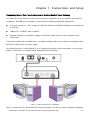
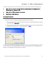
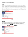
TWG850/DWG855 digital ⎢ BROADBAND RESIDENTIAL VOICE GATEWAY Important Information CAUTION CAUTION Disconnect power before To ensure reliable operation and to prevent servicing. overheating, provide adequate ventilation for this modem and keep it away from heat sources. Do not locate near heat registers or other This device is intended for heat-producing equipment. Provide for free air indoor operation only. flow around the Residential Voice Gateway and its Telephone jacks Line 1 and power supply. Line 2 must not be connected to outside wiring. NORTH AMERICAN CABLE INSTALLER: This reminder is provided to call your attention to Article 820-40 of the National Electrical Code (Section 54 of the Canadian Electrical Code, Part 1) which provides guidelines for proper grounding and, in particular, specifies that the cable ground shall be connected to the grounding system of the building as close to the point of cable entry as practical. Euro-PacketCable, Euro-DOCSIS, and DOCSIS compliant (TWG850) This product was designed according to Euro-PacketCable Specification, Euro-DOCSIS Specifications and Data over Cable Service Interface Specifications. CableHome, PacketCable, and DOCSIS compliant (DWG855) This product was designed according to CableHome Specifications, PacketCable Voice over IP Cable Telephony Specifications and Data over Cable Service Interface Specifications. It will operate on any DOCSIS-compliant Hybrid Fiber Coax (HFC) cable system and offers DOCSIS and PacketCable Baseline Privacy to promote secure internet transactions and PC-secure telephone service. Operating Information Operating Temperature: 0˚ - 40˚ C (32˚ - 104˚ F) Storage Temperature:-30˚ to 65˚ C If you purchased this product at a retail outlet, please read the following: ii Product Information Keep your sales receipt to obtain warranty parts and service and for proof of purchase. Attach it here and record the serial and model numbers in case you need them. The numbers are located on the back of the product. Model No. ____________________________Serial No ________________________________ Purchase Date: ________________________Dealer/Address/Phone: _________________________ Illustrations contained in this document are for representation only. iii Chapter 1: Connections and Setup Introduction ............................................................................................................................ 1 Residential Voice Gateway Features ................................................................................... 1 What’s on the CD-ROM ..................................................................................................... 1 Computer Requirements.................................................................................................... 3 Wall Mounting ................................................................................................................... 4 Residential Voice Gateway TWG850 Overview........................................................................... 6 Front Panel........................................................................................................................ 6 Rear Panel ......................................................................................................................... 7 Residential Voice Gateway DWG855 Overview .......................................................................... 8 Front Panel........................................................................................................................ 8 Rear Panel ....................................................................................................................... 10 Installing the Battery ....................................................................................................... 10 Relationship among the Devices ............................................................................................ 12 What the Modem Does .................................................................................................... 12 What the Modem Needs to Do Its Job............................................................................... 12 Contact Your Local Cable Company ................................................................................. 13 Connecting the Residential Voice Gateway to a Single Computer............................................ 15 Attaching the Cable TV Wire to the Residential Voice Gateway ......................................... 15 Important Connection Information .................................................................................. 16 USB Connection to One Computer ................................................................................... 16 USB Connection ............................................................................................................... 18 Using Windows 2000 for USB Connection ........................................................................ 18 Using Windows Me for USB Connection............................................................................ 22 Using Windows XP for USB Connection ............................................................................ 23 iv Ethernet Connection to One Computer ............................................................................ 25 Connecting More Than Two Computers to the Residential Voice Gateway ........................ 27 Telephone or Fax Connection .......................................................................................... 29 Activating the Residential Voice Gateway ............................................................................... 31 Chapter 2: Web Configuration Accessing the Internet ........................................................................................................... 33 Outline of Web Manager .................................................................................................. 34 Status .................................................................................................................................... 35 Software.......................................................................................................................... 35 Connection...................................................................................................................... 35 Security ........................................................................................................................... 36 Diagnostics ..................................................................................................................... 36 Wireless................................................................................................................................. 37 Basic ............................................................................................................................... 37 Security ........................................................................................................................... 39 Access Control ................................................................................................................ 42 Advanced ........................................................................................................................ 43 Bridging .......................................................................................................................... 44 Chapter 3: Additional Information Frequently Asked Questions .................................................................................................. 45 General Troubleshooting ....................................................................................................... 47 FCC Declaration of Conformity and Industry Canada Information ........................................... 49 Service Information................................................................................................................ 50 Glossary ................................................................................................................................ 51 Illustrations contained in this document are for representation only. v Chapter 1: Connections and Setup Introduction Residential Voice Gateway Features z Support Multiple Provisioning Mode z Standard RJ-45 connector for 10/100BaseT Ethernet with auto-negotiation and MDIS functions z USB Connector for USB interface z Two RJ-11 Foreign Exchange Station (FXS) ports for IP telephony z Support simultaneous voice and data communications z Two simultaneous voice conversations in the different FXS ports with different CODEC: PCM A-law, PCM-law, G.723.1, G.729, G.729a, G.729e, G.728, G.726, BV16 and BV32 z Echo Cancellation z Voice Active Detection (VAD) z DTMF detection and generation z Comfort Noise Generation (CNG) z Support V.90 fax and modem services z Transparent bridging for IP traffic z RSA and 56 bit DES data encryption security z SNMP network management support z Remote operating firmware downloading z Support Web pages and private DHCP server for status monitoring z Clear LED display z Plug and Play What’s on the CD-ROM Insert the Residential Voice Gateway CD-ROM into your CD-ROM drive to view troubleshooting tips, the internal diagnostics, and other valuable information. Note: You might need to use the CD-ROM to install the USB driver if you are connecting via the USB port. Illustrations contained in this document are for representation only. 1 Chapter 1: Connections and Setup CD-ROM Contents: z Electronic copy of this user’s guide in additional languages (PDF format) z Adobe Acrobat Reader — application you can load to read PDF format, if you don’t have it loaded already z USB drivers — required if connecting by USB z Links to Thomson and RCA web sites DOCSIS and PacketCable are trademarks of Cable Television Laboratories, Inc. 2 Chapter 1: Connections and Setup Computer Requirements For the best possible performance from your Residential Voice Gateway, your personal computer must meet the following minimum system requirements (note that the minimum requirements may vary by cable companies): IBM PC COMPATIBLE MACINTOSH** CPU Pentium preferred PowerPC or higher System RAM 16MB (32MB preferred) 24MB (32MB preferred) Operating System Windows* NT/2000/Me/XP, Mac OS** 7.6.1 or higher Linux Available Disk Space 125MB 50MB Sound Card Required for audio on CD-ROM N/A Video VGA or better (SVGA preferred) VGA or better (SVGA built-in preferred) CD-ROM Drive Required Required Ethernet 10BaseT or 100BaseT 10BaseT or 100BaseT An Ethernet card makes it possible for your computer to pass data to and from the internet. You must have an Ethernet card and software drivers installed in your computer. You will also need a standard Ethernet cable to connect the Ethernet card to your Residential Voice Gateway. USB Port USB (Windows 2000/ME/XP only) The Universal Serial Bus is a high speed bus that enables your computer to communicate simultaneously with a variety of peripherals. However, if you have other peripherals that send and receive a lot of information, such as speakers, printers or scanners, we recommend using an Ethernet card to support this modem. Illustrations contained in this document are for representation only. 3 Chapter 1: Connections and Setup Software • A TCP/IP network protocol for each machine • Microsoft Internet Explorer 4.0 or later or Netscape Navigator 4.0 or later. (5.0 and 4.7 or later, respectively, are strongly recommended.) *Windows is a trademark of Microsoft Corporation. **Macintosh and the Mac OS are trademarks of Apple Computer, Inc. Wall Mounting The number of the screw: 2 pcs Direction for wall mounting: LED panel upward. Dimension for the screw: TBD There are 4 slots on the underside of the EMTA that can be used for wall mounting. Note: When wall mounting the unit, ensure that it is within reach of the power outlet. You will need 2 suitable screws which screw diameter would be 4.4 mm to wall mount the Cable Modem or the Battery Pack. Two different wall mount directions could be chosen for the Battery Pack. To do this: 1. Ensure that the wall you use is smooth, flat, dry and sturdy and use the 4 screw holes which are 101.6 mm apart from each other. 2. 4 Fix the screws into wall, leaving their heads 3 mm (0.12 inch) clear of the wall surface. Chapter 1: Connections and Setup 3. Remove any connections to the unit and locate it over the screw heads. When in line, gently push the unit on to the wall and move it downwards to secure. Illustrations contained in this document are for representation only. 5 Chapter 1: Connections and Setup Residential Voice Gateway TWG850 Overview Front Panel The following illustration shows the front panel of the TWG850 machine: The LEDs on the front panel are described in the table below (from left to right): Tel 2 ON Boot-up Operation ON ON ON Start-up Operation Normal Operation No service Operation 6 Cable Cable Activity Link ON ON ON 0.25 second Tel 1 WirelessMessage ON 0.25 sec FLASH ON 1 sec ON X X FLASH FLASH ON ON 1 second PC Internet Link ON ON X X X X X X OFF FLASH X X X OFF OFF OFF X X X OFF OFF OFF FLASH FLASH X X X OFF OFF OFF FLASH FLASH X X X OFF OFF X X X OFF X X X X X X X X X X X X X X X X X X X X X X X X X X X OFF FLASH OFF FLASH ON OFF FLASH ON X X X X X X X X FLASH FLASH FLASH FLASH FLASH FLASH FLASH FLASH FLASH FLASH FLASH FLASH Enter Normal Operation Mode X OFF ON FLASH X X OFF FLASH X FLASH ON X X X X X X X X X X X X X X X X Wink X X 3 seconds ON followed by a flash OFF Description Power on 0.25 sec From power ON to system initialization complete Following system initialization complete to (before) DS scanning Tuning (Searching downstream signal) Ranging - Awaiting Response (DS carrier acquire, ranging in process but RNG-RSP has not been detected) Any RNG-RSP detected (Normalizing power level and timing offset) Connecting (Ranging complete, DHCP in progress) Configuring (DHCP complete, configuration file download in process) Registering and Baseline Privacy Initializing (configuration file download complete, initialize BPI if BPI is ON, registration in process) Registration complete NO Cable Link CM is registered NO Ethernet/USB carrier present Ethernet/USB TX/RX traffic Ethernet/USB carrier present, no traffic NO Cable Link Cable BSS/OSS has set the CM into de-activated state CM is registered Internet ON-OFF switch off/No RF DS/US network traffic RF DS/US network traffic No message is delivered by the MSO Email is available fro the user on the server (Implementation of the message waiting LED will be via Proprietary MIB) Wireless initiate fail or disable Wireless initiate success or enable TX/RX Wireless Traffic NACO =OFF BPI unauthorized (when BPI is ON) Chapter 1: Connections and Setup Tel 2 OFF MTA FLASH initialization FLASH ON MTA ON Operation FLASH FLASH SW X Download X Operation Tel 1 WirelessMessage FLASH OFF FLASH ON FLASH ON FLASH X X X X Cable Cable Activity Link PC Internet Link Description MTA DHCP MTA SNMP/TFTP RSIP <CM Normal Operation> Both Lines On-Hook Tel1 Off-hook, Tel2 On-hook Tel1 On-hook, Tel2 Off-hook Both Lines Off-Hook FLASH FLASH FLASH FLASH FLASH A software download and while updating the FLASH memory From Right to Left Rear Panel 15VDC: 15V DC-IN Power connector TEL1 & TEL2 Telephony RJ-11 connector ETHERNET: Ethernet 10/100BaseT RJ-45 connector USB: USB Connector REBOOT EMTA: Reboot this Residential Voice Gateway CABLE: F-Connector Illustrations contained in this document are for representation only. 7 Chapter 1: Connections and Setup Residential Voice Gateway DWG855 Overview Front Panel The following illustration shows the front panel of the DWG855 machine: The LEDs on the front panel are described in the table below (from left to right): Power ON Boot-up Operation Internet Ethernet DS US Online ON ON ON 2 3 4 ON ON ON ON ON ON X ON ON X X X X X X X X X X X X X X X X X X OFF X X X X X X X X X OFF X X X X X X X X X ON 0.25 second ON FLASH FLASH FLASH ON ON ON ON ON ON 1 second FLASH OFF ON FLASH Tel 1 Tel 2 Battery Wireless USB Description 1 DOCSIS From power ON to system initialization complete Following system initialization complete to (before) DS scanning During DS scanning and acquiring SYNC From SYNC completed, receiving UCD to ranging completed During DHCP, Start-up Operation Power on 0.25 sec configuration file ON ON ON FLASH X X X X X X X X X download, registration, ON ON ON ON X X X X X X X X X Operational (NACO=ON) OFF X X X X X X X X X Operational(NACO=OFF) OFF X X MTA DHCP and Baseline Privacy initialization ON MTA initialization FLASH FLASH ON ON ON ON X X X X ON ON ON ON X X X X OFF FLASH OFF X X MTA SNMP/TFTP ON ON ON ON X X X X FLASH FLASH OFF X X RSIP OFF OFF OFF OFF ON X X X CPE ON ON ON FLASH FLASH FLASH FLASH ON Operation ON ON No Ethernet Link X X X X X ON Ethernet Link TX/RX Ethernet Traffic Ethernet Collision OFF No USB Link ON 8 ON FLASH OFF X X X X X X X X X X X ON USB Link ON USB driver is not ready FLASH TX/RX USB Traffic Chapter 1: Connections and Setup Power CPE Operation AC Good Battery Good Internet DS US Ethernet Online 1 2 3 4 Battery Low ON X X X X X X X Battery Bad No Wireless Link X X X ON FLASH X ON ON ON ON ON FLASH ON ON ON FLASH ON ON ON ON FLASH ON ON FLASH <CM Normal Operation> ON ON ON ON FLASH ON ON ON FLASH ON On-hook ON Tel1 On-hook, Tel2 Off-hook Both Lines Off-Hook Both Lines On-Hook Tel1 Off-hook, Tel2 FLASH <CM Normal On-hook Operation> Both Lines Off-Hook Both Lines On-Hook Tel1 Off-hook, Tel2 On-hook OFF Tel1 On-hook, Tel2 Off-hook Both Lines Off-Hook Both Lines On-Hook Tel1 Off-hook, Tel2 FLASH On-hook OFF Tel1 On-hook, Tel2 ON FLASH Off-hook FLASH OFF FLASH Battery Low Both Lines Off-Hook OFF ON AC Fail Tel1 On-hook, Tel2 Off-hook ON Battery Good Wireless is not installed Tel1 Off-hook, Tel2 FLASH FLASH AC Fail TX/RX Wireless Traffic Both Lines On-Hook FLASH FLASH ON Wireless Link or disable FLASH FLASH ON AC Good Tel2 Battery Wireless USB Description OFF ON AC Good Tel1 Both Lines On-Hook Tel1 Off-hook, Tel2 OFF On-hook FLASH Tel1 On-hook, Tel2 ON Off-hook FLASH Both Lines Off-Hook Both Lines On-Hook AC Fail Battery Bad < All LEDs may be unlit due to lack of battery power> OFF < All LEDs may Tel1 Off-hook, Tel2 be unlit due to On-hook lack of battery Tel1 On-hook, Tel2 power> Off-hook Both Lines Off-Hook SW Download Operation ON FLASH FLASH ON X X X X X X X Illustrations contained in this document are for representation only. X X A software download and while updating the FLASH memory 9 Chapter 1: Connections and Setup Rear Panel TEL1 & TEL2 Telephony RJ-11 connector ETHERNET 1-4: Ethernet 10/100BaseT RJ-45 connector USB: USB Connector REBOOT EMTA: Reboot this Residential Voice Gateway CABLE: F-Connector Rating 100-240V: Power connector Installing the Battery This section provides you information of installing batteries into the modem. Follow the steps below: 1. Unplug the power cord of the power adapter from the modem if you have plugged it. 2. Remove the cover of the rear panel. There are two spare drives for you to install the battery. 10 Chapter 1: Connections and Setup 3. Insert the battery into the rear battery drive with the direction that the following picture shows. 4. Put back the cover of the rear panel. 5. Now, the cable modem is on with the power of the battery. It is not necessary for you to use power adapter again. Illustrations contained in this document are for representation only. 11 Chapter 1: Connections and Setup Relationship among the Devices This illustration shows a cable company that offers DOCSIS- and PacketCable-compliant voice/data services. What the Modem Does The Residential Voice Gateway provides high-speed Internet access as well as cost-effective, toll-quality telephone voice and fax/modem services over residential, commercial, and education subscribers on public and private networks via an existing CATV infrastructure. It can inter-operate with the PacketCable compliant headend equipment and provide the IP-based voice communications. The IP traffic can transfer between the Residential Voice Gateway and DOCSIS compliant headend equipment. The data security secures upstream and downstream communications. What the Modem Needs to Do Its Job The Right Cable Company: Make sure your local cable company provides data services that use cable TV industry-standard Euro-DOCSIS or DOCSIS-compliant and Euro-PacketCable or PacketCable-compliant technology. 12 Chapter 1: Connections and Setup The Internet/Telephony Service Provider (ISP/TSP): Your cable company provides you access to an Internet Service Provider (ISP) and Telephony Service Provider (TSP). The ISP is your gateway to the Internet and provides you with a pipeline to access Internet content on the World Wide Web (WWW). The TSP provides you with telephony access to other modems or other telephony services over the Public Switched Telephone Network (PSTN). Check with your cable company to make sure you have everything you need to begin; they’ll know if you need to install special software or re-configure your computer to make your cable internet service work for you. Contact Your Local Cable Company You will need to contact your cable company to establish an Internet account before you can use your gateway. You should have the following information ready (which you will find on the sticker on the gateway): • The serial number • The model number • The Cable Modem (CM) Media Access Control (MAC) address • The Terminal Adapter (EMTA) MAC address Illustrations contained in this document are for representation only. 13 Chapter 1: Connections and Setup Please verify the following with the cable company The cable service to your home supports Euro-DOCSIS or DOCSIS compliant two-way modem access. Your internet account has been set up. (The Media Terminal Adapter will provide data service if the cable account is set up but no telephony service is available.) You have a cable outlet near your PC and it is ready for Cable Modem service. Note: It is important to supply power to the modem at all times. Keeping your modem plugged in will keep it connected to the Internet. This means that it will always be ready whenever you need. To disconnect your computer from the Internet, use the ON/OFF button to put the modem in standby mode. Important Information Your cable company should always be consulted before installing a new cable outlet. Do not attempt any rewiring without contacting your cable company first. 14 Chapter 1: Connections and Setup Connecting the Residential Voice Gateway to a Single Computer This section of the manual explains how to connect your Residential Voice Gateway to the USB or Ethernet port on your computer and install the necessary software. Please refer to Figure 1 to help you connect your Digital Cable Modem for the best possible connection. Attaching the Cable TV Wire to the Residential Voice Gateway 1. Locate the Cable TV wire. You may find it one of three ways: a. Connected directly to a TV, a Cable TV converter box, or VCR. The line will be connected to the jack which should be labeled either IN, CABLE IN, CATV, CATV IN, etc. b. Connected to a wall-mounted cable outlet. c. Coming out from under a baseboard heater or other location. See Figure 1 for the wiring example. Notes: For optimum performance, be sure to connect your Residential Voice Gateway to the first point the cable enters your home. The splitter must be rated for at least 1GHz. Fig. 1: Basic Home Wiring Illustrations contained in this document are for representation only. 15 Chapter 1: Connections and Setup Important Connection Information The Residential Voice Gateway supports Ethernet and USB connections simultaneously. Below are important points to remember before you connect the Residential Voice Gateway. For USB connections, follow the instructions on this page. For Ethernet connections, go to page 25. For telephone and fax connections, go to page 29. USB Connection to One Computer Note: Only use the power supply provided with this unit. Using other power supplies may damage the unit. Fig. 2-1: USB Connection on TWG850 16 Chapter 1: Connections and Setup Fig. 2-2: USB Connection on DWG855 If you received an Installation/Quick Start kit with the purchase of your modem, you should use the software provided in that kit. If not, the Residential Voice Gateway CD included with your modem contains the drivers and other information you need to install your Residential Voice Gateway. Illustrations contained in this document are for representation only. 17 Chapter 1: Connections and Setup USB Connection If you do not want to use the CD-ROM, follow instructions 1 through 5 to connect the Residential Voice Gateway to the USB port on your computer. Instructions must be followed in the order they appear. 1. Connect one end of the coaxial cable to the cable connection in the wall, and the other end to the CABLE jack on the Residential Voice Gateway. 2. Connect the plug from the AC power supply into the POWER AC ADAPTER jack on the Residential Voice Gateway and plug the power supply into an AC outlet. 3. Insert the supplied Residential Voice Gateway CD-ROM. Wait momentarily for the CD window display. 4. Close all open applications and dialog boxes, including the CD window. Note: Open applications may interfere with your Residential Voice Gateway installation. 5. Connect one end of the USB cable to the USB port located on the back of your computer. Connect the other end of the USB cable to the USB port on the Residential Voice Gateway. Note: Use only the power supply that accompanied this unit. Using other power supplies may damage the unit. Next, you need to install the USB driver for your operating system. Using Windows 2000 for USB Connection Follow steps 6 through 14 if you have a Windows 2000 operating system: 18 Chapter 1: Connections and Setup 6. When the “Found New Hardware Wizard” appears, click “Next” to initiate the search for drivers for your USB device. Note: If Windows 2000 does not recognize the presence of the Residential Voice Gateway, your BIOS settings may not permit USB and/or Plug-and-Play devices. Please contact the customer service department of the computer company. 7. Choose the “Search for a suitable driver for my device (recommended)” option, and click “Next”. Illustrations contained in this document are for representation only. 19 Chapter 1: Connections and Setup 8. Choose ONLY the “CD-ROM drives” option and click “Next”. 9. The search should find the driver for the “Thomson USB CDC Devices”. To confirm that this is the case, click “Next” to continue and proceed to step 11. Otherwise, see step 10. Important: Do NOT continue if the search finds “USB Composite Device” driver. Proceed to step 10. 10. Follow these instructions ONLY if the driver found was NOT the “Thomson USB CDC Devices.” A. Click “Back” to return to the previous window. B. Ensure that you have selected the “CD-ROM” option. C. In addition to the CD-ROM option, choose “Specify a location.” Click on “Next” to continue. D. In the location box, type in your CD-ROM drive. For example, if your CD-ROM is located on the E: drive, type “E:\.” Click on “Ok” to continue. E. Click “Next” to continue. F. The search should find either “RCA or Thomson USB Cable Modem”. 20 Chapter 1: Connections and Setup 11. Windows should now prompt you to install the “Thomson USB CDC Devices”. Click “Next” to install the driver. At this point your PC needs to copy Windows 2000 specific files. If these files are not located on your hard drive, you may need to insert your Windows 2000 installation media (i.e., Windows 2000 CD-ROM), but first remove the Residential Voice Gateway CD-ROM. 12. After the Windows specific files are copied, you may be asked for another USB driver file named “NETRCACM.SYS,” located on the Residential Voice Gateway CD-ROM. Remove the Windows 2000 CD-ROM (if necessary), and reinsert the Residential Voice Gateway CD-ROM that accompanied your Residential Voice Gateway. 13. Click on “Finish” to complete the process. 14. The Residential Voice Gateway installation is now complete. To validate a proper installation, perform the following instructions: A. Click on the “Start” icon in the lower left-hand corner of your screen. B. Select “Settings,” followed by “Control Panel.” The “Control Panel” window appears. C. Double-click on the “System” icon, select the “Hardware” tab, and choose “Device Manager.” D. Scroll down the list until you come to “Network Adapters.” Double-click on “Network Adapters.” E. The “RCA Digital Cable Modem” should exist. If the “RCA or Thomson Digital Cable Modem” does not exist, the Residential Voice Gateway was NOT installed correctly. Please install again. Illustrations contained in this document are for representation only. 21 Chapter 1: Connections and Setup Using Windows Me for USB Connection Follow steps 6 through 9 if you have a Windows Me operating system: 6. Windows Me will briefly display the “Found New Hardware Wizard,” and automatically proceed to the “Add New Hardware Wizard”. Choose the “Automatic search for a better driver (Recommended)” option, and click “Next.” Note: If Windows Me does not recognize the presence of the Residential Voice Gateway, i.e., the “Add New Hardware Wizard” did not automatically appear, your BIOS settings may not permit USB and/or Plug-and-Play devices. Please contact your computer’s customer service department. 7. The automatic search should find and install the driver for the “RCA or Thomson Digital Cable Modem”. Click on “Finish” to complete the process. 8. When the “System Settings Change” window appears, click “Yes” to restart your computer. 9. The Thomson Digital Cable Modem installation is now complete. To validate a proper installation, perform the following instructions: A. Click on the “Start” icon in the lower left-hand corner of your screen. B. Select “Settings,” followed by “Control Panel.” The “Control Panel” window will appear. C. Double-click on the “System” icon, and select the “Device Manager.” D. Scroll down the list until you come to “Network Adapters.” Double-click on “Network Adapters.” E. The “RCA or Thomson Digital Cable Modem” should exist. If “RCA or Thomson Digital Cable Modem” does not exist, the Digital Cable Modem was NOT installed correctly. 22 Chapter 1: Connections and Setup Using Windows XP for USB Connection Follow steps 6 through 9 if you have a Windows XP operating system: 6. Windows XP will display the “Welcome to the Found New Hardware Wizard,” and ask whether you would like the Windows to connect to Windows Update to search for software, Choose “No, not this time” and click “Next”. 7. The “Found New Hardware Wizard” will then display the device name and ask you to insert the installation CD-ROM that came with the unit. Choose the “Install from a list or specific location (Advanced)” option, and click “Next.” Note: If Windows XP does not recognize the presence of the Residential Voice Gateway, i.e., the “Welcome to the New Hardware Wizard” did not automatically appear, your BIOS settings may not permit USB and/or Plug-and-Play devices. Please contact the customer service department of the computer company. Illustrations contained in this document are for representation only. 23 Chapter 1: Connections and Setup 8. Select “Search Removable Media (floppy, CD-ROM…)” and click on “Next”, then your computer will install the drivers for the “RCA or Thomson Digital Cable Modem”. 9. When the “Completing the Found New Hardware Wizard” window appears, click “Finish” to complete the process. 10. The Residential Voice Gateway installation is now complete. To validate a proper installation, perform the following instructions: A. Click on the “Start” icon in the lower left-hand corner of your screen. B. Select “Settings,” followed by “Control Panel.” The “Control Panel” window will appear. C. Double-click on the “System” icon, and select the “Device Manager.” D. Scroll down the list until you come to “Network Adapters.” Double-click on “Network Adapters.” E. The “RCA or Thomson Digital Cable Modem” should exist. If “RCA or Thomson Digital Cable Modem” does not exist, the Residential Voice Gateway was NOT installed correctly. 24 Chapter 1: Connections and Setup Ethernet Connection to One Computer Make the connections to the modem in the following sequence: 1. Connect one end of the coaxial cable to the cable connection in the wall, and the other end to the CABLE jack on the Residential Voice Gateway. 2. Connect the plug from the AC power supply into the POWER AC ADAPTER jack on the Residential Voice Gateway, and plug the power supply into an AC outlet. Note: Use only the power supply that accompanied this unit. Using other adapters may damage the unit. 3. Connect one end of the Ethernet cable (straight-wired, see below) to the Ethernet port on the back of your computer, and the other end to the ETHERNET port on the Residential Voice Gateway. Make sure that the Ethernet cable is straight-wired (not “null” or crossover-wired). However, you will need a crossover-type cable if you are connecting the modem to a hub, or a hub within a port switch that provides the same function. Fig.3-1: Ethernet Connection on TWG850 Illustrations contained in this document are for representation only. 25 Chapter 1: Connections and Setup Fig.3-2: Ethernet Connection on DWG855 26 Chapter 1: Connections and Setup Connecting More Than Two Computers to the Residential Voice Gateway For TWG 850, if you need to connect more than two computers or if you need to connect two computers, but USB is not available, you’ll need the following additional equipment: Crossover-wired, or “null,” category 5 Ethernet cable for the EMTA Gateway to be connected to the hub 10BaseT or 100BaseT Hub or Switch Straight through, or standard, category 5 Ethernet cable (one for each computer to be connected) If you have a hub with an uplink port*, a straight through cable can be used in combination with that port in lieu of the crossover cable. *An uplink port has a small switch on it to change the polarity of the connection. It can accept either a crossover or a straight cable, depending on the setting. Fig.4-1: Hub Connection for TWG850 Note: You may need to check with your service provider in order to connect multiple computers. Illustrations contained in this document are for representation only. 27 Chapter 1: Connections and Setup If you need to connect more than two computers to DWG 855, simply connect the computers to the Ethernet ports on the rear panel. Fig.4-2: Multiple-PC Connection for DWG855 Note: You may need to check with your service provider in order to connect multiple computers. 28 Chapter 1: Connections and Setup Telephone or Fax Connection When properly connected, most telephony devices can be used with the Residential Voice Gateway just as with conventional telephone service. To make a normal telephone call, pick up the handset; listen for a dial tone, then dial the desired number. For services such as call waiting, use the hook switch (or FLASH button) to change calls. The following procedures describe some of the possible connection schemes for using telephony devices with the Residential Voice Gateway. 1. Connect a standard phone line cord directly from the phone (fax machine, answering machine, caller ID box, etc.) to one of the LINE jacks on the Residential Voice Gateway. 2. If there is a phone line in your home which is NOT connected to another telephone service provider, connect a standard phone line cord from a jack on this line to one of the LINE jacks of the Residential Voice Gateway. Connect a standard phone line cord directly from the phone (fax machine, answering machine, caller ID box, etc.) to one of the other jacks in the house that uses that line. 3. If you have a multi-line telephone, connect a standard phone line cord (not an RJ-14 type line cord) from the phone to the LINE jacks on the Residential Voice Gateway. (Other phones can be added to each line by using standard phone line splitters. Fig. 5-1: Phone/Fax Connection on TWG850 Illustrations contained in this document are for representation only. 29 Chapter 1: Connections and Setup Fig. 5-2: Phone/Fax Connection on DWG855 30 Chapter 1: Connections and Setup Activating the Residential Voice Gateway After you install the Residential Voice Gateway and turn it on for the first time (and each time the modem is reconnected to the power), it goes through several steps before it can be used. Each of these steps is represented by a different pattern of flashing lights on the front of the modem. Note: All indicators flash once before the initialization sequence. If all of the lights are flashing sequentially, it means the Residential Voice Gateway is automatically updating its system software. Please wait for the lights to stop flashing. You cannot use your modem during this time. Do not remove the power supply or reset the Residential Voice Gateway during this process. Illustrations contained in this document are for representation only. 31 Chapter 1: Connections and Setup 32 Chapter 2: Web Configuration To make sure that you can access the Internet successfully, please check the following first. 1. Make sure the connection (through Ethernet or USB) between the Residential Voice Gateway and your computer is OK. 2. Make sure the TCP/IP protocol is set properly. 3. Subscribe to a Cable Company. Accessing the Internet Once your host PC is properly configured; please proceed as follows: 1. Start your web browser and type the private IP address of the Residential Voice Gateway on the URL field: 192.168.0.1. 2. After connecting to the device, you will be prompted to enter username and password. By default, the username is “ ” and the password is “admin”. If you login successfully, the main page will appear. From now on this Residential Voice Gateway acts as a web server sending HTML pages according to your request. You can configure the settings on the webpage and apply them to the device. Illustrations contained in this document are for representation only. 33 Chapter 2: Web Configuration Outline of Web Manager The main screen will be shown as below. Main Menu: It includes Status and Wireless. Title: It indicates the title of this management interface. e.g., Software in this example. Main Window: It is the current workspace of the web management, containing configuration or status information. 34 Chapter 2: Web Configuration Status Software This page shows the software and hardware information and the status of the Residential Voice Gateway. Connection This page shows current connection status containing startup procedures, downstream status, upstream status, CM online information, and so on. Illustrations contained in this document are for representation only. 35 Chapter 2: Web Configuration Security This page is used to change the password that enables you to access the gateway web pages next time. The default User ID is cablelabs, and the password is admin. The password can be a maximum of 8 characters and is case sensitive. In addition, this page can be used to restore the gateway to its original factory settings. Use this with caution, as all the settings you have made will be lost. To perform this reset, set Restore Factory Defaults to Yes and click Apply. This has the same effect as a factory reset using the rear panel reset switch, where you hold in the switch for 15 seconds, then release. After proper configuration, click Apply to invoke the settings. Diagnostics This page offers basic diagnostic tools for you to utilize when connectivity problems occur. You may use the ping diagnostics or trace route function, just enter the information needed and press Start Test; the Result will be displayed in the lower part of the window. Press Abort Test to stop, and Clear Results to clear the result contents. 36 Chapter 2: Web Configuration Wireless Basic To set the basic configuration for the wireless features, click Basic from the Wireless menu. Wireless Mac Address: Displays the Wireless Mac Address information. Network Name (SSID): The SSID is the identification of this device; the system will detect the SSID and display it in this field for your reference. You may modify it. Network Type: If you choose Open, the EMTA will periodically broadcast its SSID to allow the wireless clients within the range to recognize its presence. You may choose Closed to hide the SSID. Country: Please select a proper location from the drop down menu. Channel: There are 11 channels that you can choose. Choose the one that is suitable for this device. The channel that you currently use will be displayed after Current. Interface: Choose Enabled to enable the wireless settings. Choose Disabled to close the wireless function. Apply: After proper configuration, click Apply to invoke the settings. Restore Wireless Defaults: Click this button to restore the device to the factory defaults for wireless settings. Illustrations contained in this document are for representation only. 37 Chapter 2: Web Configuration SecureEasySetup: It radically simplifies Wi-Fi® wireless LAN configuration, allowing even first-time Wi-Fi users to setup and secure their wireless networks with the push of a button. Create SES Network: Press this button to create the SES network environment. A dialog window will show up while creating the SES network. When the SES network is created, the dialog window will display a success message. After creating the SES network, the SSID will be changed, as the following figure shows. Open SES Window: Press this button to open the SES window. At this moment, if the client device supports SES function, the user only has to push a corresponding button on device, and the connection process will start automatically and Wi-Fi Protected Access (WPA) will be activated simultaneously. 38 Chapter 2: Web Configuration Security This page allows you to configure the Network Authentication. Here provides several different modes of wireless security. You will have to enter proper information according to the mode you select. WPA (Wi-Fi Protected Access)/WPA2: It must be used in conjunction with an authentication server such as RADIUS to provide centralized access control and management. It can provide stronger encryption and authentication solution than none WPA modes. WPA2 is the second generation of WPA security WPA-PSK (WPA-Pre-Shared Key) /WPA2-PSK (WPA2-Pre-Shared Key): It is useful for small places without authentication servers such as the network at home. It allows the use of manually-entered keys or passwords and is designed to be easily set up for home users. WEP Encryption: You can choose 64-bit or 128-bit according to your needs. If you choose Disabled, the Network Keys will not be shown on this page. If selected, the data is encrypted using the key before being transmitted. For example, if you set 128-bit in this field, then the receiving station must be set to use the128 Bit Encryption, and have the same Key value too. Otherwise, it will not be able to decrypt the data. Apply: After proper configuration, click Apply to invoke the settings. Illustrations contained in this document are for representation only. 39 Chapter 2: Web Configuration WEP Encryption If you select WEP (64-bit or 128-bit), you can adjust the following settingsShared Key Authentication: Decide whether to set the shared key Optional or Required by selecting from the drop-down menu. Network Key 1 to 4: The system allows you to enter four sets of the WEP key. For 64-bit WEP mode, the key length is 5 characters or 10 hexadecimal digits. As for 128-bit WEP mode, the key length is 13 characters or 26 hexadecimal digits. Current Network Key: Select one set of the network key (from 1 to 4) as the default one. PassPhrase: You can enter ASCII codes into this field. The range is from 8 characters to 64 characters. For ASCII characters, you can key in 63 characters in this field. If you want to key in 64 characters, only hexadecimal characters can be used. Generate WEP Keys: Click this button to generate the PassPhrase. 802.1x Authentication If you enable the 802.1x authentication function, you will have to offer the following informationRADIUS Server: RADIUS Server is a protocol for carrying authentication, authorization, and configuration information between a Network Access Server which desires to authenticate its links and a shared Authentication Server. Please key in the IP Address for the RADIUS Server. RADIUS Port: Besides the IP address of the RADIUS Server, you have to enter the port number for the server. Port 1812 is the reserved RADIUS-authentication port described in RFC 2138. Earlier AP (RADIUS clients) use port 1945. The default value will be shown on this box. You can keep and use it. RADIUS Key: A RADIUS Key is like a password, which is used between IAS and the specific RADIUS client to verify identity. Both IAS and the RADIUS client must be use the same RADIUS Key for successful communication to occur. Enter the RADIUS Key. 40 Chapter 2: Web Configuration WPA/WPA2 For the WPA/WPA2 network Authentication, the settings that you can adjust including WPA/WPA2 Encryption, RADIUS Server, RADIUS Port, RADIUS Key, Group Key Rotation Interval, and WPA/WPA2 Re-auth Interval. WPA/WPA2 Encryption: There are three types that you can choose, TKIP*, AES**, TKIP+AES. * TKIP takes the original master key only as a starting point and derives its encryption keys mathematically from this mater key. Then it regularly changes and rotates the encryption keys so that the same encryption key will never be used twice ** AES provides security between client workstations operating in ad hoc mode. It uses a mathematical ciphering algorithm that employs variable key sizes of 128, 192 or 256 bits. RADIUS Server/RADIUS Port/RADIUS Key: Please refer to the previous page. Group Key Rotation Interval: Key in the time for the WAP group key rotation interval. The unit is second. With increasing rekey interval, user bandwidth requirement is reduced. WPA/WPA2 Re-auth Interval: When a wireless client has associated with the Residential Voice Gateway for a period of time longer than the setting here, it would be disconnected and the authentication will be executed again. The default value is 3600, you may modify it. WPA-PSK/ WPA2-PSK For the WPA-PSK/WPA2-PSK network Authentication, the settings that you can adjust including WPA/WPA2 Encryption, WPA Pre-Shared Key, and Group key Rotation Interval. WPA Pre-Shared Key: Please type the key to be between 8 and 63 characters, or 64 hexadecimal digits. Only the devices with a matching key that you set here can join this network. WPA/WPA2 Encryption & WPA Group Rekey Interval: Please refer to the WPA/WPA2 part. Illustrations contained in this document are for representation only. 41 Chapter 2: Web Configuration Access Control This page allows you to make access control to the AP or connected clients by offering the MAC Addresses of the clients. MAC Restrict Mode: Click Disabled to welcome all of the clients on the network; select Allow to permit only the clients on the list to access the cable modem; or choose Deny to prevent the clients on the list to access this device. MAC Address: Enter the MAC addresses of the connected clients into the fields, and then click Apply to add them to the list for access control. Apply: After proper configuration, click Apply to invoke the settings. Connected Clients: The information of current connected clients will be displayed here. 42 Chapter 2: Web Configuration Advanced This page allows you to configure the data rates and Wi-Fi thresholds. 54gTM Network Mode: There are three modes for you to choose, please check the specification of your wireless card and choose a proper setting. 54gTM Protection: Select Auto to turn on the 54gTM protection; select Off to turn down the protection. XpressTM Technology: When Xpress is turned on, aggregate throughput (the sum of the individual throughput speeds of each client on the network) can improve by up to 27% in 802.11g-only networks, and up to 75% in mixed networks comprised of 802.11g and 802.11b standard equipment. Click Enabled to start this function; choose Disabled to close this function. AfterburnerTM Technology: When enabled, the data transmission will be faster for the clients. Yet, the clients must support 125Mbps throughput, then you can choose Enabled. Otherwise, choose Disabled. Rate: It decides the speed of data transmission. There are several rates provided here for you to choose. Choose any one of it according to your needs by using the drop-down menu. Output Power: This setting decides the output power of this device. You may use it to economize on electricity by selecting lower percentage of power output. Beacon Interval: Set the period of beacon transmissions to allow mobile stations to locate and identify a BSS. The measure unit is “time units” (TU) of 1024 microseconds. DTIM Interval: The value you set here is used to inform mobile stations when multicast frames that have been buffered at the Residential Voice Gateway will be delivered and how often that delivery occurs. Illustrations contained in this document are for representation only. 43 Chapter 2: Web Configuration Fragmentation Threshold: Set the number of the fragmenting frames to make the data to be delivered without errors induced by the interference. Frames longer than the value you set here are fragmented before the initial transmission into fragments no longer than the value of the threshold. RTS Threshold: Set the value for sending a request to the destination. All the frames of a length greater than the threshold that you set here will be sent with the four-way frame exchange. And, a length less than or equal to the value that you set will not be proceeded by RTS. Apply: After proper configuration, click Apply to invoke the settings. Bridging This page allows you to configure the WDS features. WDS (Wireless Distribution System) is a system that enables the interconnection of access points wirelessly. It may also be referred to as repeater mode because it appears to bridge and accept wireless clients at the same time (unlike traditional bridging). Wireless Bridging: Choose Disabled to shutdown this function; select Enabled to turn on the function of WDS. Remote Bridges: Enter the MAC Addresses of the remote Bridges to relay the signals for each other. Apply: After proper configuration, click Apply to invoke the settings. 44 Chapter 3: Additional Information Frequently Asked Questions Q. What if I don’t subscribe to cable TV? A. If cable TV is available in your area, data and voice service may be made available with or without cable TV service. Contact your local cable company for complete information on cable services, including high-speed internet access. Q. How do I get the system installed? A. Professional installation from your cable provider is strongly recommended. They will ensure proper cable connection to the modem and your computer. However, your retailer may have offered a self installation kit, including the necessary software to communicate with your cable ISP. Q. Once my Residential Voice Gateway is connected, how do I get access to the Internet? A. Your local cable company provides your internet service*, offering a wide range of services including email, chat, and news and information services, and a connection to the World Wide Web. Q. Can I watch TV, surf the Internet, and talk to my friends through the Residential Voice Gateway at the same time? A. Absolutely! Q. What do you mean by “Broadband?” A. Simply put, it means you’ll be getting information through a “bigger pipe,” with more bandwidth, than a standard phone line can offer. A wider, “broader” band means more information, more quickly. Q. What is EURO-DOCSIS/DOCSIS and what does it mean? A. “Data over Cable Service Interface Specifications” is the industry standard that most cable companies are adopting as they upgrade their systems. Should you ever decide to move, the Cable Modem will work with all upgraded cable systems that are EURO-DOCSIS/DOCSIS-compliant. Q. What is Euro-PacketCable/PacketCable and what does it mean? A. Like DOCSIS, Euro-PacketCable/PacketCable is the industry standard for telephony services that most cable companies are adopting as they upgrade their systems. Should you ever decide Illustrations contained in this document are for representation only. 45 Chapter 3: Additional Information to move, the Residential Voice Gateway will work with all upgraded cable systems that are Euro-PacketCable/PacketCable-compliant. Q. What is SecureEasySetup and what does it mean? A. The software radically simplifies Wi-Fi® wireless LAN configuration, allowing even first-time Wi-Fi users to setup and secure their wireless networks with the push of a button. Whereas a typical Wi-Fi installation requires a user to manually configure several technical settings on each wireless device, SecureEasySetup simply requires a user to push a button on the wireless router/ Access Point, and a corresponding button on the PC or other client device. This automates the connection process and activates Wi-Fi Protected Access (WPA), the strongest security standard available to protect home and small business wireless networks from unauthorized use. Q. What is Xpress Technology and what does it mean? A. It is one of the popular performance-enhancing WiFi technologies, designed to improve wireless network efficiency and boost throughput. It is more efficient in mixed environments, and it can work with 802.11a/b/g networks. When Xpress is turned on, aggregate throughput (the sum of the individual throughput speeds of each client on the network) can improve by up to 27% in 802.11g-only networks, and up to 75% in mixed networks comprised of 802.11g and 802.11b standard equipment. The technology achieves higher throughput by by re-packaging data, reducing the number of overhead control packets, so that more useful data can be sent during a given amount of time. * Monthly subscription fee applies. 46 Chapter 3: Additional Information General Troubleshooting You can correct most problems you have with your product by consulting the troubleshooting list that follows. I can’t access the internet. z Check all of the connections to your Residential Voice Gateway. z Your Ethernet card or USB port may not be working. Check each product’s documentation for more information. z The Network Properties of your operating system may not be installed correctly or the settings may be incorrect. Check with your ISP or cable company. All of the lights are flashing in sequence. z This means the Residential Voice Gateway is automatically updating its system software. Please wait for the lights to stop flashing. The updating process typically lasts less than one minute. z Do not remove the power supply or reset the Residential Voice Gateway during this process. I can’t get the modem to establish an Ethernet connection. z Even new computers don’t always have Ethernet capabilities – be sure to verify that your computer has a properly installed Ethernet card and the driver software to support it. z Check to see that you are using the right type of Ethernet cable. The modem won’t register a cable connection (CABLE LINK light not on continuously). z If the modem is in Initialization Mode, the INTERNET light will be flashing. Call your Cable Company if it has not completed this 5-step process within 30 minutes, and note which step it is getting stuck on. (See page 24 for details.) z The modem should work with a standard RG-6 coaxial cable, but if you’re using a cable other than one your Cable Company recommends, or if the terminal connections are loose, it may not work. Check with your Cable Company to determine whether you’re using the correct cable. Illustrations contained in this document are for representation only. 47 Chapter 3: Additional Information z If you subscribe to video service over cable, the cable signal may not be reaching the modem. Confirm that good quality cable television pictures are available to the coaxial connector you are using by connecting a television to it. If your cable outlet is “dead”, call your Cable Company. z Verify that the Cable Modem service is DOCSIS-compliant and PacketCable-compliant by calling your cable provider. I don’t hear a dial tone when I use a telephone. z Telephone service is not activated. If the rightmost light on the Residential Voice Gateway stays on while others flash, check with your TSP or cable company. z If the Residential Voice Gateway is connected to existing house telephone wiring, make sure that another telephone service is not connected. The other service can normally be disconnected at the Network Interface Device located on the outside of the house. z If using the second line on a two-line telephone, use a 2-line to 1-line adapter cable. For more Usage and Troubleshooting Tips use the web site links provided on the CD-ROM: http://www.cable-modem.rca.com/help 48 Chapter 3: Additional Information FCC Declaration of Conformity and Industry Canada Information This device complies with Part 15 of the FCC Rules. Operation is subject to the following two conditions: (1) this device may not cause harmful interference, and (2) this device must accept any interference received, including interference that may cause undesired operation. Trade Name: RCA Model: TWG850/DWG855 Equipment Classification: Computing Device Accessory Responsible Party: Thomson Inc. 10330 N. Meridian Street Indianapolis, IN 46290 Telephone 317-415-4151 This equipment has been tested and found to comply with the limits for a Class B digital device, pursuant to Part 15 of the FCC Rules. These limits are designed to provide reasonable protection against harmful interference in a residential installation. This equipment generates, uses, and can radiate radio frequency energy and, if not installed and used in accordance with the instructions, may cause harmful interference to radio communications. guarantee that interference will not occur in a particular installation. However there is no If this equipment does cause harmful interference to radio or television reception, which can be determined by turning the equipment off and on, the user is encouraged to try and correct the interference by one or more of the following measures: Reorient or relocate the receiving antenna. Increase the separation between the equipment and receiver. Connect this equipment into an outlet on a circuit different from that to which the receiver is connected. Consult the dealer or an experienced radio/TV technician for help. FCC regulations state that unauthorized changes or modifications to this equipment may void the user’s authority to operate it. This Class B digital apparatus meets all requirements of the Canadian Interference Causing Equipment Regulations. Illustrations contained in this document are for representation only. 49 Chapter 3: Additional Information Service Information If you purchased or leased your Residential Voice Gateway directly from your cable company, then warranty service for the Digital Cable Modem may be provided through your cable provider or its authorized representative. For information on 1) Ordering Service, 2) Obtaining Customer Support, or 3) Additional Service Information, please contact your cable company. If you purchased your Residential Voice Gateway from a retailer, see the enclosed warranty card. 50 Chapter 3: Additional Information Glossary 10BaseT – Unshielded, twisted pair cable with an RJ-45 connector, used with Ethernet LAN (Local Area Network). “10” indicates speed (10 Mbps), “Base” refers to baseband technology, and “T” means twisted pair cable. Authentication - The process of verifying the identity of an entity on a network. DHCP (Dynamic Host Control Protocol) – A protocol which allows a server to dynamically assign IP addresses to workstations on the fly. Ethernet card – A plug-in circuit board installed in an expansion slot of a personal computer. The Ethernet card (sometimes called a Network Interface Card or NIC) takes parallel data from the computer, converts it to serial data, puts it into a packet format, and sends it over the 10BaseT or 100BaseT LAN cable. EURO-DOCSIS/ DOCSIS (Data Over Cable Service Interface Specifications) – A project with the objective of developing a set of necessary specifications and operations support interface specifications for Cable Modems and associated equipment. F Connector – A type of coaxial connector, labeled CABLE IN on the rear of the Residential Voice Gateway, that connects the modem to the cable system. HTTP (HyperText Transfer Protocol) – Invisible to the user, HTTP is used by servers and clients to communicate and display information on a client browser. Hub – A device used to connect multiple computers to the Residential Voice Gateway. IP Address – A unique, 32-bit address assigned to every device in a network. An IP (Internet Protocol) address has two parts: a network address and a host address. This modem receives a new IP address from your cable operator via DHCP each time it goes through Initialization Mode. Key exchange - The swapping of mathematical values between entities on a network in order to allow encrypted communication between them. MAC Address – The permanent “identity” for a device programmed into the Media Access Control layer in the network architecture during the modem’s manufacture. Network Driver – A file that is loaded on the computer to allow the computer to recognize the Ethernet card or USB port. NID - Network Interface Device, the interconnection between the internal house telephone wiring Illustrations contained in this document are for representation only. 51 Chapter 3: Additional Information and a conventional telephone service provider’s equipment. These wiring connections are normally housed in a small plastic box located on an outer wall of the house. It is the legal demarcation between the subscriber’s property and the service provider’s property. Euro-PacketCable/ PacketCable – A project with the objective of developing a set of necessary telephony specifications and operations support interface specifications for Residential Voice Gateways and associated equipment used over the DOCSIS-based cable network. PSTN (Public Switched Telephone Network) – The worldwide voice telephone network which provides dial tone, ringing, full-duplex voice band audio and optional services using standard telephones. Provisioning - The process of enabling the Media Terminal Adapter (MTA) to register and provide services over the network. SecureEasySetup – The software radically simplifies Wi-Fi® wireless LAN configuration, allowing even first-time Wi-Fi users to setup and secure their wireless networks with the push of a button. Whereas a typical Wi-Fi installation requires a user to manually configure several technical settings on each wireless device, SecureEasySetup simply requires a user to push a button on the wireless router/ Access Point, and a corresponding button on the PC or other client device. This automates the connection process and activates Wi-Fi Protected Access (WPA), the strongest security standard available to protect home and small business wireless networks from unauthorized use. TCP/IP (Transmission Control Protocol/Internet Protocol) – A networking protocol that provides communication across interconnected networks, between computers with diverse hardware architectures and various operating systems. TFTP - Trivial File Transfer Protocol, the system by which the Media Terminal Adapter’s configuration data file is downloaded. TSP - Telephony Service Provider, an organization that provides telephone services such as dial tone, local service, long distance, billing and records, and maintenance. Universal Serial Bus (USB) – USB is a “plug-and-play” interface between a computer and add-on devices, such as an Residential Voice Gateway. Xpress Technology - One of the popular performance-enhancing WiFi technologies, designed to improve wireless network efficiency and boost throughput. It is more efficient in mixed environments, and it can work with 802.11a/b/g networks. 52 Chapter 3: Additional Information Please do not send any products to the Indianapolis address listed in this manual or on the carton. This will only add delays in service for your product. Thomson Inc. 10330 North Meridian Street Indianapolis, IN 46290 © 2005 Thomson Inc. Trademark(s) Registered Marca(s) Registrada(s) Printed in USA TOCOM 1691104A Illustrations contained in this document are for representation only. 53 Chapter 3: Additional Information 54