1
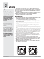
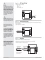
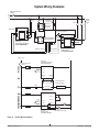
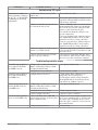
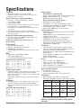
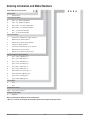
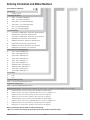
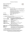
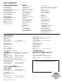
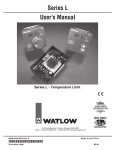
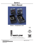
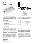
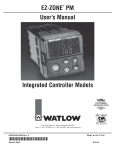
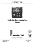
Series C & Series TM
User’s Manual
Series C - On-Off Temperature Controller
Series TM - Temperature Indicator
TOTAL
CUSTOMER
SATISFACTION
3 Year Warranty
ISO 9001
Registered Company
1241 Bundy Boulevard., Winona, Minnesota USA 55987
Phone: +1 (507) 454-5300, Fax: +1 (507) 452-4507 http://www.watlow.com
0600-0044-0000 Rev. E
February 2008
Winona, Minnesota USA
Made in the U.S.A.
$5.00
Safety Information
We use note, caution and warning symbols throughout this book to draw your attention to important operational and safety information.
A “NOTE” marks a short message to alert you to an important detail.
ç
CAUTION or
WARNING
Ó
Electrical
Shock Hazard
CAUTION or WARNING
A “CAUTION” safety alert appears with information that is important for protecting
your equipment and performance. Be especially careful to read and follow all cautions that apply to your application.
A “WARNING” safety alert appears with information that is important for protecting you, others and equipment from damage. Pay very close attention to all warnings that apply to your application.
The safety alert symbol, ç (an exclamation point in a triangle) precedes a general
CAUTION or WARNING statement.
The electrical hazard symbol, Ó (a lightning bolt in a triangle) precedes an electric
shock hazard CAUTION or WARNING safety statement.
Technical Assistance
If you encounter a problem with your Watlow controller, review your configuration information to verify that your selections are consistent with your application: inputs, outputs, alarms,
limits, etc. If the problem persists, you can get technical assistance from your local Watlow representative (see back cover), by e-mailing your questions to [email protected] or by
dialing +1 (507) 494-5656 between 7 a.m. and 5 p.m., Central Standard Time (CST). Ask for for
an Applications Engineer. Please have the following information available when calling:
• Complete model number
• System wiring information
• Basic Controller User’s Manual
Warranty
These controllers are manufactured by ISO 9001-registered processes and are backed by a
three-year warranty.
Return Material Authorization (RMA)
1. Call Watlow Customer Service, (507) 454-5300, for a Return Material Authorization (RMA)
number before returning any item for repair. We need this information:
• Ship to address
• Bill to address
• Contact name
• Phone number
• Method of return shipment
• Your P.O. number
• Detailed description of the problem
• Any special instructions
• Name and phone number of person returning the product.
2. Prior approval and an RMA number, from the Customer Service Department, is needed
when returning any unused product for credit. Make sure the RMA number is on the outside of
the carton, and on all paperwork returned. Ship on a Freight Prepaid basis.
3.
After we receive your return, we will examine it and try to verify the reason for the return.
4. In cases of manufacturing defect, we will enter a repair order, replacement order or issue
credit for material returned.
5. To return products that are not defective, goods must be be in new condition, in the original boxes and they must be returned within 120 days of receipt. A 20 percent restocking charge
is applied for all returned stock controls and accessories.
6.
If the unit is unrepairable, it will be returned to you with a letter of explanation.
7.
Watlow reserves the right to charge for no trouble found (NTF) returns.
The Series C and Series TM user’s manual is copyrighted by Watlow Winona, Inc.,
© November 2006 with all rights reserved.
1
Overview
Watlow's Series C family of basic temperature controllers* provide an economical controller solution for
applications where simple on/off control is needed.
These controllers are available with or without an
operator interface and can be ordered in square 1/8th
DIN panel mount, din rail mount, open board or potted module design configurations. Push-on, quick connect spade terminal or removable screw clamp style
terminal block ordering options provide the electrical
connections.
The microprocessor design platform provides improvements in the performance, repeatability, and
accuracy offered by Watlow's current line of basic temperature control products.
The Series CV includes an operator interface to allow viewing and selection of the control set point. A
red four-character, seven-segment LED displays the set
point. It is also available with a push-to-show process
option. The set point selection is made with a continuous turn, velocity-sensitive rotary encoder. Set point
range temperature values are customer definable in
the product configuration part number.
The Series CF offers fixed control points. These
units are supplied without an operator interface. Operating set point temperature values are customer definable in the product configuration part number.
The Series TM is a temperature indicator only version. It is available in DIN rail or panel mount configurations.
The features and performance of these products
make them ideally suited for a wide range of industrial
control applications in the food preparation, industrial
machinery, packaging and plastic markets.
Watlow's Series C and TM controllers include industry-leading service, support and a 3-year warranty.
Watlow Series C/TM
*Also available in an FM-approved limit version.
Features and Benefits
Four-Character LED Display
• Improves Set Point adjustment accuracy.
Fixed or Adjustable Set Points
• Tamper Proof Operation.
• Control Flexibility.
Set Point Adjustment Options
• Rotary encoder.
• Tactile increment and decrement keys.
Push to Set Option
• Reduce accidental set point adjustments.
Push to Display Process Option
• Allows viewing of process value.
Multiple Mounting Options
• Minimizes installation time.
Heat or Cool Operation
• Application flexibility.
Fahrenheit or Celsius Operation with Indication
• Application flexibility.
Sensor Break Protection
• Provides positive system shutdown.
Agency Approvals
• Meets requirements for agency certification.
• NEMA 4X/IP65 seal panel-mount versions available.
• W.E.E.E; CE; RoHS
Microprocessor Based Technology
• Accurate and repeatable control.
Stock to Four Day Delivery
• 1 •
Chapter 1 Over view
2
Installation
Installing the Open Board Controller
61.7 mm
2.43 in
45.07 mm
1.775 in
61.7 mm
2.43 in
56.3 mm
2.22 in
61.7 mm
2.43 in
45.07 mm
1.775 in
56.3 mm
2.22 in
SWDC+ .6
N.O.
55.9 mm
2.20 in
61.7 mm
2.43 in
SWDC- .7
COM
55.9 mm
2.20 in
N.C. .8
L1
L2 .9
.10
Terminal Designation Sticker
Use M2.5 (#4) mounting
hardware, not included
Terminal Designation Sticker
Use M2.5 (#4) mounting
hardware, not included
Screw Terminal Model
Spade Terminal Model
Figure 2a
1. Locate and drill four 3.2 mm (0.125 in) holes in the desired panel location. See Figure 2a for hole locations.
2. Mount the controller using four M2.5 (#4) screws.
Installing the Potted Controller
Terminal Designation Sticker
46.6 mm
1.84 in
70.1 mm
2.76 in
35.1 mm
1.38 in
35.1 mm
1.38 in
102.9 mm
4.05 in
88.9 mm
3.50 in
Terminal Designation Sticker
Terminal Designation Sticker
Use [3.5M] #6 hardware,
not included
Figure 2b
1. Drill two 5 mm (0.187 in) diameter holes in the desired panel location. See Figure 2b for hole locations.
2. Mount the controller using two M3.5 (#6) screws.
Watlow Series C
• 2 •
Chapter 2 Installation
81.8 mm
(3.22 in)
94.7 mm
(3.73 in)
78.1 mm
(3.08 in)
To install or remove,
press down here.
See Installing/ Removing
the DIN Rail Controller
procedures below.
90.7 mm
(3.57 in)
39.1 mm
(1.54 in)
Part Number Label
80.0 mm
(3.07 in)
DIN rail, upper
mounting clip
101.6 mm
(4.00 in)
80.3 mm
112.3 mm
(3.16 in)
(4.42 in)
1. SW-1
2. SW-2
35 mm x 7.5 mm
DIN rail is not included
with the assembly
3.TC-/S1
4.TC+/S2
5.
S3
Terminal Designation Sticker
Agency Label
Panel mounting the bracket requires
two M3.5 (#6) screws, not included
To install, press in here.
To remove, pull out here.
See Mounting/Removing the
DIN Rail Controller procedures below.
Spade Terminal Model
Figure 3a
Screw Terminal Model
Tactile Key Model
rail bracket and the case. Rotate the screwdriver to
release the DIN rail bracket hooks from the ridges
on the case, while firmly pushing the controller out
the front of the DIN rail bracket. Alternate back
and forth between the top and then the bottom. Be
sure to support the controller as it comes out of the
bracket. See Figure 3b.
Figure 3b
Sub-Panel Mounting
1. Using the controller as a location template, mark
both mounting holes.
2. Drill and tap two 2.7 mm (0.106 in) diameter holes
in the desired panel location. See Figure 3a
above for hole locations.
3. Mount the controller using two M3.5 (#6) screws.
Press forward
with thumb
DIN Rail Mounting
1. Place the DIN rail upper mounting clip on the top
edge of the DIN rail. See Figure 3a. DIN rail
spec, DIN 50022, 35 mm x 7.5 mm (1.38 in x 0.30
in).
2. Press down firmly on the top back edge of the DIN
rail bracket and push in on the bottom, front edge
of the bracket. The controller “snaps” securely onto
the rail. See Figure 3a. If the controller does not
snap on, check to see if the DIN rail is bent. Minimum clipping distance is 34.8 mm (1.37 in), the
maximum is 35.3 mm (1.39 in).
Removing the DIN Rail Controller
1. Remove power from the system.
2. Remove all the wiring connections from the back of
the controller.
Insert flat blade
screwdriver here
3. While pressing down on the top, back edge of the
DIN rail bracket, pull forward on the bottom, front
edge of the DIN rail bracket. See Figure 3a.
Removing the Controller from the DIN Rail
Bracket
1. Remove power from the system.
2. Remove all the wiring connections from the back of
the controller.
3. Remove the DIN rail bracket from the DIN rail.
4. Insert a flat blade screwdriver between the DIN
Watlow Series C
• 3 •
Chapter 2 Installation
72.4 mm
(2.85 in)
68.0 mm
(2.68 in)
Panel Cutout
Panel Thickness
1.52 to 3.18 mm
(0.060 to 0.125 in)
72.4 mm
(2.85 in)
68.0 mm
(2.68 in)
19.1 mm
(0.75 in)
minimum
19.1 mm
(0.75 in)
minimum
Spade Terminal Model
Customer Front Panel
Part Number Label
84.5 mm square
(3.33 in)
Terminal Blocks Locations
on Screw Terminal Models
Mounting Bracket
6.4 mm
(0.25 in)
Tactile Key,
Screw Terminal Model
19.2 mm
(0.76 in)
51.7 mm
(2.04 in)
Spade Terminal Model
Figure 4
1. Make the panel cutout using the mounting dimensions above.
2. Remove mounting bracket from the back of the controller.
3. If your controller has a gasket, check to see that the
gasket is not twisted, and is seated within the case
bezel flush with the panel. Place the case in the
cutout. Make sure the gasket is between the panel
cutout and the case bezel.
Watlow Series C
Screw Terminal Models
lation. See Figure 4. Slide the collar firmly against
the back of the panel, getting it as tight as possible.
To ensure a tight seal, use your thumb to lock the
tabs into place while pressing the case from side to
side. Don’t be afraid to apply enough pressure to install the controller. The tabs on each side of the collar have teeth that latch into the ridges. Each tooth
is staggered at a different height, so only one of the
tabs on each side are ever locked into the ridges
at a time. Confirm that the tabs on one side of the
collar correspond with those on the opposite side.
Make sure the two corresponding tabs are the only
ones locked in the ridges at the same time. If the
corresponding tabs are not supporting the case at
the same time, you will not have a NEMA 4X seal.
Installing the Square 1/8 DIN Panel Mount
Controller
4. While pressing the front of the case firmly against
the panel, slide the mounting collar over the back of
the control. The tabs on the collar must line up with
the mounting ridges on the case for secure instal-
Contact your local Greenlee supplier for the appropriate
punch kit and cutout tool for rapid mounting.
5. Insert the control chassis into its case and press the
bezel to seat it. Make sure the inside gasket is also
seated properly and not twisted. The hardware installation is complete. Proceed to the wiring section.
• 4 •
Chapter 2 Installation
2. Insert the controller into the panel cutout.
3. While pressing the bezel firmly against the panel,
slide the mounting bracket over the back of the controller. Be sure the levers on the mounting bracket
line up with the teeth on the case.
4. Press the bracket up to the back of the panel. The
controller should fit tightly in the panel cutout.
Removing the Panel Mount Square 1/8 DIN
Controller
1. Remove power from the system.
2. Remove all the wiring connections from the back of
the controller.
3. Slide a thin, wide tool (putty knife) under all three
mounting tabs, top then bottom, while pushing forward on the back of the case. Be ready to support
the controller as it slides out of the panel cutout.
Watlow Series C
• 5 •
Chapter 2 Installation
3
Wiring
Ó
Warning:
Use National Electric (NEC) or
other country-specific standard
wiring and safety practices when
wiring and connecting this controller to a power source and to
electrical sensors or peripheral
devices. Failure to do so may
result in damage to equipment
and property, and/or injury or
loss of life.
Note: Insulated terminals required for quick connect style
terminals.
For quick connect terminals 1,
2, 6, 7, 8, 9, and 10, AMP P/N
3-520406-2 or equivalent recommended. Use Amp crimp tool
P/N 58078-3, insert 90391-3.
For quick connect terminals 3, 4,
and 5, AMP P/N 2-520405-2 or
equivalent recommended. Amp
crimp tool P/N 58078-3, insert
58079-3.
The terminals on the back of the Series C and Series TM controllers are
the same for all of the package styles. They are 6.3 mm (0.25 in) quick connect,
push on style terminals or removable screw terminal block. The terminal style
is an ordering option.
Check the part number to determine your hardware configuration. Refer to
the wiring diagrams appropriate for your controller’s configuration.
All outputs are referenced to a de-energized state.
Wiring Guidelines
1. Use the correct thermocouple type per the model number on the case sticker of the unit. See dimension drawings for sticker locations.
•
Use correct thermocouple polarity. Red is usually negative.
• If you must extend thermocouple leads, use thermocouple extension
wire to minimize errors.
• Be sure you have good crimp connections on your thermocouple connections.
• Insulate the thermocouple mounting from the mounting surface to
prevent heat migration input errors.
• Thermocouple leads should be routed separately from any high voltage
lines.
• Long lead lengths create electrical resistance and there is not any lead
resistance compensation. When using a two or three-wire RTDs, there will
be an additional 2.6° C (4.7° F) error for every 1Ω of lead length resistance.
That resistance when added to the resistance of the RTD element, can result in erroneous input to the temperature controller.
2. In electrically-noisy environments (heavy switching contactors, motors,
solenoids, etc.), use shielded thermocouple lead wire with the shield connected at the sensor end only.
3. Use a separate thermocouple to maintain the limit function of this
controller; do not parallel thermocouple input from the primary controller.
4. All wiring and fusing must conform to the National Electric Code (NEC)
NFPA70 and any other locally applicable codes.
5. Fuse the independent load voltage on the L1 (hot) side and connect it to
the common (C) side of the relay.
Note: The model number determines the connection terminal style. See below for terminal locations.
1
2
3
4
5
Watlow Series C
6
7
8
9
10
• 6 •
1
2
3
4
5
6
7
8
9
10
Chapter 3 Wiring
ç
Warning:
Use National Electric (NEC) or
other country-specific standard
wiring and safety practices when
wiring and connecting this controller to a power source and to
electrical sensors or peripheral
devices. Failure to do so may
result in damage to equipment
and property, and/or injury or
loss of life.
Figure 7a — AC Power Wiring
• Nominal voltage options:
- 24VÅ (ac)
- 120VÅ (ac)
- 230 to 240VÅ (ac)
1
2
3
Note: Insulated terminals required for quick connect style
terminals.
For quick connect terminals 1,
2, 6, 7, 8, 9, and 10, AMP P/N
3-520406-2 or equivalent recommended. Use Amp crimp tool
P/N 58078-3, insert 90391-3.
8
4
5
Ó
WARNING: If high voltage is applied to a low-voltage controller,
irreversible damage will occur.
6
7
9
10
L2
L2
L1
L1
Figure 7b — Thermocouple Input
Thermocouples are polarity sensitive. The negative lead (usually red) must be
connected to TC-.
• Input impedance: >10 MΩ
1
2
Thermocouple -
TC-
Thermocouple + TC+
3
4
5
For quick connect terminals 3, 4,
and 5, AMP P/N 2-520405-2 or
equivalent recommended. Amp
crimp tool P/N 58078-3, insert
58079-3.
6
7
8
9
10
Figure 7c — RTD Input
Note: To prevent ground loops,
isolation needs to be maintained
from input to output when using a switched DC output. Ungrounded thermocouples recommended.
(100 Ω Platinum DIN curve 0.00385 Ω/Ω/°C)
• Terminals S2 and S3 must be shorted for a two-wire RTD
• Nominal excitation current: 125 μA
3-Wire RTD*
2-Wire RTD
RTD S1
RTD S1
RTD S2
RTD S3
RTD S2
S3
1
2
S1 3
S2 4
S3
5
6
7
8
9
10
*No lead resistance
compensation
Watlow Series C
• 7 •
Chapter 3 Wiring
ç
Figure 8a — Switched DC Output
Warning:
Use National Electric (NEC)
or other country-specific
standard wiring and safety
practices when wiring and
connecting this controller to
a power source and to electrical sensors or peripheral
devices. Failure to do so may
result in damage to equipment and property, and/or
injury or loss of life.
• Minimum output voltage at 10 mA, 5VÎ (dc)
• Maximum voltage output into an infinite load, 24VÎ (dc)
• Minimum load impedance, 500Ω
• Offstate leakage, 100μAÎ (dc)
• Not recommended for switching mechanical relays
• Output supplies power
1
2
SWDC+ Switched DC+
+ External
6
SWDC- Switched DC- Load
7
3
8
4
5
9
For quick connect terminals
3, 4, and 5, AMP P/N 2520405-2 or equivalent recommended. Amp crimp tool
P/N 58078-3, insert 58079-3.
SWDC+
10
Note: Insulated terminals required for quick connect style
terminals.
For quick connect terminals
1, 2, 6, 7, 8, 9, and 10, AMP
P/N 3-520406-2 or equivalent
recommended. Use Amp
crimp tool P/N 58078-3, insert 90391-3.
Switched DC
17V (dc) unreg
300Ω
SWDC-
300Ω
Internal Circuitry
Figure 8b — Mechanical Relay Output
• Form C contacts
• 8 A, resistive
• 250 VA pilot duty, 120/240VÅ (ac), inductive
• 240VÅ (ac) maximum
• 30VÎ (dc) maximum
• See Quencharc note
• For use with ac or dc
• Minimum load current 100 mA
• Output does not supply power
Quencharc Note:
Switching pilot duty loads
(relay coils, solenoids, etc.)
with the mechanical relay
output options requires use
of an R.C. suppressor.
Watlow carries the R.C. suppressor Quencharc brand
name, which is a trademark
of ITW Paktron. Watlow Part
No. 0804-0147-0000.
Customer supplied Quencharc
for pilot duty, inductive loads
only. See note.
External
Load
1
2
6 N.O. Normally Open
C
Common
7
N.C. Normally Closed
8
3
4
5
L2
L1
9
Mechanical Relay
10
N.O.
COM.
N.C.
Internal Circuitry
Watlow Series C
• 8 •
Chapter 3 Wiring
System Wiring Examples
Power Disconnect
Switch
L1
120V~(ac)
L2
Customer
Supplied
Quencharc
Fuse
Fuse
Not used
1
2
Fuse
High Limit
Mechanical
Contactor
coil
Fuse
6 SWDC+
SWDC7
8
L2
9
TC- 3
TC+ 4
5
10
Reset Switch
(customer supplied)
SW-1
SW-2
L1
+
SSR-240-10A-DC1
in out Solid-State Relay
Series CV
Temperature Controller
CVB1JH00000100C
1
2
TC-
N.O.
COM
7
N.C.
8
L2
9
6
3
TC+
4
5
10
Heater
120V• • (ac)• •
L1
L2
Series CV
Temperature Controller
CVB1JH00000100C
Power Disconnect
Switch
1
L1
Series LF
Limit Control
LFC4JW0120AAAAA
Limit Sensor
Process Sensor
1
HighTemp.
Light
10 L1
3
2
4 (+)
3
5 (-)
L2 9
4
TC+
3
TC-
SWDC+
6
4
2
SWDC7
6
7
3 to 32
(+) V• • (dc) in (-)
SSR-240-10A-DC1
Solid-State Relay
1 CR-1
5
1
8
1
11
48 to 260
V• • out
9
10 L1
6
7
8
14 (+)
10
15 (-)
11
12
1
17
13
4
TC+
3 TC7 COM
2
L2 9
SW-1 1
9
Heater
10
SW-2 2
2
12
13
N.O. 6
16
N.C. 8
1 CR
R
18
Series LF
Limit Controller
LFC4JW0120AAAAA
2
2
High-Temperature Light
Figure 9 — System Wiring Examples
Watlow Series C
• 9 •
Chapter 3 Wiring
4
User Interface
Variable Set Point, Standard
CV _ _ (1, 2, 5 or 6) _ _ _ _ _ _ _ _ _ A
C
CVV
LED Display: Indicates
the set point. Display
momentarily blinks when
new set point value is
entered.
F or C Indicator Light: Lit
to indicate if unit is configured
for degrees Fahrenheit or
degrees Celsius.
F
C
LOAD
LOAD Indicator Light: Lit
when output is energized.
Finger Tip Indent: Insert
finger tip into indent for
quick and easy set point
changes.
Set Point Knob: To increase
set point, turn knob clockwise.
To decrease set point, turn
knob counterclockwise. Set
point can be changed at any
time. The new set point is
entered 3 seconds after the
knob stops moving.
Figure 10a — Variable Set Point Standard
Interface
Variable Set Point, Standard
CV _ _ (A, B, C or D) _ _ _ _ _ _ _ _ _ A
Figure 10b — Variable
Set Point with Tactile
Keys
CV
LED Display: Indicates
the set point. Display
momentarily blinks when
new set point value is
entered.
F or C Indicator Light: Lit
to indicate if unit is configured
for degrees Fahrenheit or
degrees Celsius.
F
C
LOAD
LOAD Indicator Light: Lit
when output is energized.
Increment and Decrement Keys:
Press the Up-Arrow key to
increase the set point.
Press the Down-Arrow key to
decrease the set point.
The new set point is entered 3
seconds after the last key stroke.
To adjust the Calibration Offset on models with tactile
keys, first hold down both the Increment and Decrement keys for five seconds. The display will first show
[`CAL] for five seconds, then it will display the Calibration Offset value. Adjust the value with the Increment and Decrement keys (range: -30 to 30°). The new
value will take effect three seconds after the last key
stroke. The display will blink, then return to the primary display after five seconds.
Watlow Series C
To change the temperature units on models with
tactile keys, first hold down both the Increment and
Decrement keys for ten seconds. The display will show
[F``C] for two seconds. Adjust the units with the Increment and Decrement keys. The new value will take
effect three seconds after the last key stroke. The display will blink, then return to the primary display after
five seconds. The set point value, process value and
offset will automatically adjust to the new temperature
scale.
• 10 •
Chapter 4 User Inter face
Variable Set Point, Push for Process
CV _ (1, 2, 5 or 6) _ _ _ _ _ _ _ _ _ _ B
C
CVV
F
C
LED Display: Indicates set point,
until the PROCESS key is pressed.
Process value (actual temperature)
is displayed until the PROCESS key
is released.
PROCESS Key: Press and hold
this key to display process
(actual temperature) value. Set
point is not adjustable until key
is released.
F or C Indicator Light: Lit
to indicate if unit is configured
for degrees Fahrenheit or
degrees Celsius.
LOAD
LOAD Indicator Light: Lit
when output is energized.
PROCESS
Finger Tip Indent: Insert
finger tip into indent for
quick and easy set point
changes.
Set Point Knob: To increase
set point, turn knob clockwise.
To decrease set point, turn
knob counterclockwise. The
new set point is entered 3
seconds after the knob stops
moving. Set point will not
change while the PROCESS
key is pressed.
Figure 11a —
Variable Set Point,
Push for Process
Interface
Variable Set Point, Push for Process
CV _ (A, B, C or D) _ _ _ _ _ _ _ _ _ _ B
CV
F
C
LED Display: Indicates set point,
until the PROCESS key is pressed.
Process value (actual temperature)
is displayed until the PROCESS key
is released.
PROCESS Key: Press and hold
this key to display process
(actual temperature) value. Set
point is not adjustable until key
is released.
LOAD
LOAD Indicator Light: Lit
when output is energized.
PROCESS
Increment and Decrement Keys:
Press the Up-Arrow key to
increase the set point.
Press the Down-Arrow key to
decrease the set point.
The new set point is entered 3
seconds after the last key stroke.
The set point will not change while
the PROCESS key is pressed.
To adjust the Calibration Offset on models with tactile
keys, first hold down both the Increment and Decrement keys for five seconds. The display will first show
[`CAL] for five seconds, then it will display the Calibration Offset value. Adjust the value with the Increment and Decrement keys (range: -30 to 30°). The new
value will take effect three seconds after the last key
stroke. The display will blink, then return to the primary display after five seconds.
Watlow Series C
F or C Indicator Light: Lit
to indicate if unit is configured
for degrees Fahrenheit or
degrees Celsius.
Figure 11b —
Variable Set Point,
Push for Process
Interface with Tactile Keys
To change the temperature units on models with
tactile keys, first hold down both the Increment and
Decrement keys for ten seconds. The display will show
[F``C] for two seconds. Adjust the units with the Increment and Decrement keys. The new value will take
effect three seconds after the last key stroke. The display will blink, then return to the primary display after
five seconds. The set point value, process value and
offset will automatically adjust to the new temperature
scale.
• 11 •
Chapter 4 User Inter face
Variable Set Point, Push to Set
CV _ (1, 2, 5 or 6) _ _ _ _ _ _ _ _ _ _ C
CV
F or C Indicator Light: Lit
to indicate if unit is configured
for degrees Fahrenheit or
degrees Celsius.
F
C
LED Display: Indicates
the set point.
LOAD
PUSH TO SET Key:
Press and hold key to
adjust the set point
temperature. The new set
point is entered 3 seconds
after the knob stops
moving. Set point will not
change unless PUSH TO
SET key is pressed.
LOAD Indicator Light: Lit
when output is energized.
PUSH
TO SET
Finger Tip Indent: Insert
finger tip into indent for
quick and easy set point
changes.
Set Point Knob: To increase
set point, turn knob clockwise.
To decrease set point, turn
knob counterclockwise. The
new set point is entered 3
seconds after the knob stops
moving.
Figure 12a — Variable
Set Point, Push to Set Interface
Figure 12b — Variable
Set Point, Push to Set Interface with Tactile Keys
Variable Set Point, Push to Set
CV _ (A, B, C or D) _ _ _ _ _ _ _ _ _ _ C
CV
F or C Indicator Light: Lit
to indicate if unit is configured
for degrees Fahrenheit or
degrees Celsius.
F
C
LED Display: Indicates
the set point.
LOAD
PUSH TO SET Key:
Press and hold key to
adjust the set point
temperature. Set point will
not change unless PUSH
TO SET key is pressed.
LOAD Indicator Light: Lit
when output is energized.
PUSH TO
SET
Increment and Decrement Keys:
Press the Up-Arrow key to
increase the set point.
Press the Down-Arrow key to
decrease the set point.
The new set point is entered 3
seconds after the last key stroke.
To adjust the Calibration Offset on models with tactile
keys, first hold down both the Increment and Decrement keys for five seconds. The display will first show
[`CAL] for five seconds, then it will display the Calibration Offset value. Adjust the value with the Increment and Decrement keys (range: -30 to 30°). The new
value will take effect three seconds after the last key
stroke. The display will blink, then return to the primary display after five seconds.
Watlow Series C
To change the temperature units on models with
tactile keys, first hold down both the Increment and
Decrement keys for ten seconds. The display will show
[F``C] for two seconds. Adjust the units with the Increment and Decrement keys. The new value will take
effect three seconds after the last key stroke. The display will blink, then return to the primary display after
five seconds. The set point value, process value and
offset will automatically adjust to the new temperature
scale.
• 12 •
Chapter 4 User Inter face
Variable Set Point, Push to Set
CV _ (1, 2, 5 or 6) _ _ _ _ _ _ _ _ _ _ D
CV
F
C
LED Display: Indicates
the process value until
the Push to Set Key is
operated.
PUSH TO SET Key:
The process value (Actual
Temperature) is displayed
when this key is not
operated. When this key is
depressed, the set point is
displayed and can be
adjusted.
F or C Indicator Light: Lit
to indicate if unit is configured
for degrees Fahrenheit or
degrees Celsius.
LOAD
LOAD Indicator Light: Lit
when output is energized.
PUSH
TO SET
Finger Tip Indent: Insert
finger tip into indent for
quick and easy set point
changes.
Set Point Knob: To increase
set point, turn knob clockwise.
To decrease set point, turn
knob counterclockwise. The
new set point is entered 3
seconds after the knob stops
moving.
Figure 13a — Variable
Set Point, Push to Set Interface
Figure 13b — Variable
Set Point, Push to Set Interface with Tactile Keys
Variable Set Point, Push to Set
CV _ (A, B, C or D) _ _ _ _ _ _ _ _ _ _ D
CV
F
C
LED Display: Indicates
the process value until
the Push to Set Key is
operated.
PUSH TO SET Key:
The process value (Actual
Temperature) is displayed
when this key is not
operated. When this key is
depressed, the set point is
displayed and can be
adjusted.
LOAD
LOAD Indicator Light: Lit
when output is energized.
PUSH TO
SET
Increment and Decrement Keys:
Press the Up-Arrow key to
increase the set point.
Press the Down-Arrow key to
decrease the set point.
The new set point is entered 3
seconds after the last key stroke.
To adjust the Calibration Offset on models with tactile
keys, first hold down both the Increment and Decrement keys for five seconds. The display will first show
[`CAL] for five seconds, then it will display the Calibration Offset value. Adjust the value with the Increment and Decrement keys (range: -30 to 30°). The new
value will take effect three seconds after the last key
stroke. The display will blink, then return to the primary display after five seconds.
Watlow Series C
F or C Indicator Light: Lit
to indicate if unit is configured
for degrees Fahrenheit or
degrees Celsius.
To change the temperature units on models with
tactile keys, first hold down both the Increment and
Decrement keys for ten seconds. The display will show
[F``C] for two seconds. Adjust the units with the Increment and Decrement keys. The new value will take
effect three seconds after the last key stroke. The display will blink, then return to the primary display after
five seconds. The set point value, process value and
offset will automatically adjust to the new temperature
scale.
• 13 •
Chapter 4 User Inter face
Temperature Indicator
TM _ _ _ _ _ _ _ _ _ _ _ _ _
T
M
TM
F
C
LED Display: Indicates
the process value.
F or C Indicator Light: Lit
to indicate if unit is configured
for degrees Fahrenheit or
degrees Celsius.
Figure 14 — Temperature Indicator Interface
Watlow Series C
• 14 •
Chapter 4 User Inter face
Troubleshooting
Indication
On indicating controls, the
display is not illuminated.
Probable Cause(s)
Corrective Action
• Power supply switch off.
• Turn switch on.
• Fuse blown.
• Replace fuse (check cause of failure).
• Breaker tripped.
• Reset breaker (check cause of failure).
• Safety interlock door switch activated. • Close door.
• Separate system limit control latched. • Reset limit controller.
• Wiring incorrect or open.
• Check wiring.
• Power supply voltage incorrect.
• Verify input power.
• Defective controller.
• Repair or replace controller.
Troubleshooting thermocouple inputs
Temperature reading is
incorrect, showing a sensor error, [Er;In] , or LOAD
LED is switching at the
wrong temperature.
Temperature reading is decreasing, but actual process
is increasing.
• Calibration offset is incorrect (tactile
models only).
Check calibration offset.
• Settings for degree C or F is incorrect. Check model part number for degree C or F.
If model has Increment/Decrement keys then
C/F setting is adjustable.
• Sensor or controller may be bad.
Sensor connections may be bad.
• Place a jumper wire across the thermocouple input terminals. The display should
indicate ambient temperature. If it does, the
controller is OK.
For controllers without the ability to view
process temperature:
- Decrease set point below ambient temperature, LOAD LED should be off for heating
controllers and on for cooling controllers.
- Increase set point above ambient temperature. LOAD LED should be on for heating
controllers and off for cooling controllers.
• Ambient temperature in the control
cabinet is over 70°C.
• Measure temperature in cabinet to ensure
it is below 70C. Vent cabinet or add fans if
necessary.
• Ground loop problem. Can occur
when using a switched DC output and
a grounded thermocouple.
• Remove power from the system. Use an
ohm meter to measure resistance between
output DC- and the thermocouple sheath. If
there is continuity, replace sensor with an
ungrounded thermocouple.
• Thermocouple polarity is reversed. In
the US, red wire insulation denotes the
negative wire.
• Check thermocouple connections. All connections, including extension wire must
maintain the correct polarity. Correct polarity
problems.
Temperature reading is
• Sensor is bad. Thermocouple is shortreading low and not increas- ed.
ing while actual process
temperature is increasing.
• Check thermocouple connections. Check
thermocouple wire insulation to make sure
it is not damaged, causing the wires to short
(making a new junction).
Temperature reading is
offset from actual process
temperature, or the output
switches on or off at the
wrong temperature. The offset changes with changes in
process temperature.
• Check thermocouple connections. Check to
make sure that only thermocouple extension
wire of the correct type was used to extend
thermocouple leads. Replace if necessary.
Watlow Series C
• Copper wire was used instead of thermocouple extension wire. Connectors
of metals different than thermocouple
metal were used to splice or make connections.
• 15 •
Troubleshooting
Indication
Probable Cause(s)
Corrective Action
Troubleshooting RTD inputs
Temperature reading is in• Calibration offset incorrect (tactile
correct, showing a sensor er- models only).
ror, [Er;In] , or LOAD LED • Settings for degree C or F is incorrect.
is switching at the wrong
temperature.
Check calibration offset
Check model part number for degree C or F.
If model has Increment/Decrement keys then
C/F setting is adjustable.
• Sensor or controller may be bad. Sensor connections may be bad.
• Place a 110 ohm resistor across the sensor
input terminals. The display should indicate
25°C (77°F). If it does, the controller is OK.
Sensor or connections may be bad.
For controllers without the ability to view
process temperature:
- Decrease set point below ambient temperature, LOAD LED should be off for heating
controllers and on for cooling controllers.
- Increase set point above ambient temperature. LOAD LED should be on for heating
controllers and off for cooling controllers.
• Ambient temperature in the control
cabinet is over 70°C (158°F).
• Measure temperature in cabinet to ensure
it is below 70°C (158°F). Vent cabinet or add
fans if necessary.
• Sensor connections may be bad. Excessive lead wire resistance.
• Check sensor connections. Measure lead
wire resistance. There will be a 2.6°C (4.7°F)
error for every ohm of lead wire resistance.
Troubleshooting controller outputs
Controller output signal is
not on when it should be.
Load LED is not on.
• Temperature reading is incorrect on
display of indicating controls or limit.
See input troubleshooting.
• See input troubleshooting.
• Set point is not set correctly.
• Verify set point setting.
Controller output signal is
not on when it should be.
Load LED is on.
• Output wiring is incorrect.
• Verify wiring. Relay outputs act as a
switch, they do not source power.
For DC output controls, voltage should be
about 20VDC with no load. Greater than 5
volts with load of 500 Ω or greater.
Control output signal is on
when it should not be on.
Load LED is on.
• Temperature reading is incorrect on
display of indicating controls or limit.
see input troubleshooting.
• See input troubleshooting.
• Set point is not set correctly.
• Verify set point setting.
• Control output is defective.
• Repair or replace controller.
• Power switching device (SSR, HG
relay, mechanical relay) is shorted. Controller outputs shorted.
• Remove wires from output of control to input of power switching device. If load is still
on, replace power switching device. If load
turns off, replace controller or sensor. See input troubleshooting.
• Output wiring is incorrect.
• Verify wiring.
Load is on when it should
not be on. Load LED is off.
Watlow Series C
• 16 •
Troubleshooting
Specifications
Controller
• Microprocessor based, on-off control mode.
• Nominal switching hysteresis, typically 1.7°C (3°F).
• Input filter time: 1 second
Operator Interface (model dependent)
• Four digit , 7 segment LED displays, .28" high.
• °F or °C indicator LED.
• LOAD indicator LED.
• Continuous turn, velocity sensitive rotary encoder for set
point adjustment, on rotary-knob models.
• Front panel key on Push for Set Point or Push for Process options.
• No operator interface on fixed set point models.
• Increment/Decrement keys for set point adjustment on
tactile key models.
Standard Conditions For Specifications
• Rated line voltage, 50 to 60Hz, 0 to 90% RH non-condensing, 15-minute warm-up.
Calibration ambient range: 25°C (77°F) ±3°C
Sensor Input
Thermocouple
• Grounded or ungrounded.
• Type E, J, K, T thermocouple types.
• >10 MΩ input impedance
• 250 nV input referenced error per 1Ω source resistance.
RTD
• 2-wire or 3-wire platinum, 100 Ω
• DIN curve (.00385 curve)
• 125 μA nominal RTD excitation current
Input Accuracy Span Range
Type E:
-200
Type J:
0
Type K:
-200
Type T:
-200
RTD (DIN):-200
to 800°C or -328
to 750°C or
32
to 1,250°C or -328
to 350°C or -328
to 800°C or -328
to
to
to
to
to
1,470°F
1,382°F
2,282°F
662°F
1,472°F
Thermocouple Input
• Calibration accuracy: ±1% of input accuracy span, ±1° at
standard conditions and actual calibration ambient.
Exception: Type T, ±2.4% of input accuracy span for -200
to 0° (-328 to 32°F)
• Temperature stability: ±0.3 degree per degree change in
ambient.
RTD Input
• Calibration accuracy ±1% of input accuracy span ±1° at
standard conditions and actual calibration ambient.
• Temperature stability: ±0.2 degree per degree change in
ambient
Allowable Operating Ranges
Type E:
-200
Type J:
-210
Type K:
-270
Type T:
-270
RTD (DIN):-200
to 800°C or -328 to
to 1,038°C or -346 to
to 1,370°C or -454 to
to 400°C or -454 to
to 800°C or -328 to
Output Types
Switched DC (non-isolated)
• Supply voltage maximum: 24VÎ (dc) into an infinite load.
• Supply voltage minimum: 5VÎ (dc) at 10 mA
• Minimum load impedance: 500 Ω
Electromechanical Relay, Form C
• Minimum load current: 100 mA
• 8 A @ 240VÅ (ac) or 30VÎ (dc) maximum, resistive
• 250 VA pilot duty, 120/240VÅ (ac) maximum, inductive
• Use RC suppression for inductive loads
• Electrical life 100,000 cycles at rated current
Agency Approvals
• UL®873 Recognized Temperature Controller and Indicator. File E43684.
• NEMA 4X/IP65 on panel mount package options with
tactile keys for set point.
• UL®197 Reviewed for use in cooking appliances.
• W.E.E.E; CE - See Declaration of Conformity.
• ANSI Z21.23 Gas Appliance Thermostat approval.
• Temperature Control and Indicator CSA 22.2 No. 24.
• RoHS Directive (2002-95-EC)
Terminals
• 6.4 mm (0.25 in) quick connect, push-on terminals. See order options. Refer to Wiring section for
crimp-on terminal recommendations.
• Removable screw clamp style terminal blocks. See
order options.
• Wire gauge 0.1 to 4 mm2 (30 to 12 AWG). Strip
length, 8 mm (0.30 in).
• Torque: 0.8 Nm (7 in-lb) maximum.
Power
• 24VÅ (ac) +10%; -15%; 50/60 Hz, ±5%
• 120VÅ (ac) +10%; -15%; 50/60 Hz, ±5%
• 230 to 240VÅ (ac) +10%; -15%; 50/60 Hz, ±5%
• 10VA maximum power consumption
• Data retention upon power failure via nonvolatile memory
Operating Environment
• 0 to 70°C (32 to 158°F)
• 0 to 90% RH, non-condensing
• Storage temperature: -40 to 85°C (-40 to 185°F)
Dimensions
• DIN Rail model can be DIN rail or chassis mount
DIN rail spec DIN 50022, 35 mm x 7.5 mm (1.38 in x 0.30 in)
1,470°F
1,900°F
2,500°F
750°F
1,472°F
Style
Width
Height
Depth
Open board
61.7 mm
(2.43 in)
61.7 mm
(2.43 in)
45.1 mm
(1.78 in)
Potted
70.1 mm
(2.76 in)
102.9 mm
(4.05 in)
46.6 mm
(1.84 in)
DIN Rail
78.1 mm
(3.08 in)
112.3 mm
(4.42 in)
90.7 mm*
(3.57 in)
Square 1/8
DIN Panel
72.4 mm
(2.85 in)
72.4 mm
(2.85 in)
Behind panel
51.7 mm
(2.04 in)
*Depth including DIN rail, 94.7 mm (3.73 in)
Note: These specifications are subject to change without
prior notice.
Watlow Series C
• 17 •
Specifications
Ordering Information and Model Numbers
On-off controller, No user interface
C F
_ _ _ _
_ _ _ _
A A A A
_
Set Point Type
F
Fixed Set Point
Line Voltage and Output
B
120VÅ (ac), Switched DC Output
C
120VÅ (ac), 8 Amp Relay Output
D
230 to 240VÅ (ac), Switched DC Output
E
230 to 240VÅ (ac), 8 Amp Relay Output
F
24VÅ (ac), Switched DC Output
G
24VÅ (ac), 8 Amp Relay Output
Controller Package
1
Panel Mount, 1/8 DIN Square -Spade Terminals
2
DIN Rail Mount -Spade Terminals
3
Open Board, not potted -Spade Terminals
4
Potted Case -Spade Terminals
5
Panel Mount, 1/8 DIN Square -Screw Terminals
6
DIN Rail Mount -Screw Terminals
7
Open Board, not potted -Screw Terminals
Sensor and Sensor Operating Range
H
Type J -346 to 1900 Degrees F
J
Type J -210 to 1038 Degrees C
K
Type K -454 to 2500 Degrees F
L
Type K -270 to 1370 Degrees C
M
Type T -454 to 750 Degrees F
N
Type T -270 to 400 Degrees C
P
100 Ω RTD -328 to 1472 Degrees F
R
100 Ω RTD -200 to 800 Degrees C
S
Type E -328 to 1470 Degrees F
T
Type E -200 to 800 Degrees C
Control Mode
H
Heat
C
Cool
Fixed Set Point Value *
XXXX
Control Set Point Value**
Overlay/Custom Options
A
Standard
*Note: Set point must fall within the sensor operating range.
**Note: A (-) is used in the left digit of the operating range to indicate negative temperature values.
Watlow Series C
• 18 •
Ordering Information
Ordering Information and Model Numbers
On-off controller, LED Display
C V
_ _ _ _
_ _ _ _
_ _ _ _
_
Set Point Type
V
Variable Set Point
Line Voltage and Output
B
120VÅ (ac), Switched DC Output
C
120VÅ (ac), 8 Amp Relay Output
D
230 to 240VÅ (ac), Switched DC Output
E
230 to 240VÅ (ac), 8 Amp Relay Output
F
24VÅ (ac), Switched DC Output
G
24VÅ (ac), 8 Amp Relay Output
Controller Package
1
Panel Mount, 1/8 DIN Square, Rotary Knob -Spade Terminals
2
DIN Rail Mount, Rotary Knob -Spade Terminals
5
Panel Mount, 1/8 DIN Square, Rotary Knob -Screw Terminals
6
DIN Rail Mount, Rotary Knob -Screw Terminals
A
NEMA 4X Panel Mount, Tactile Keys, Spade Terminals
B
DIN Rail Mount, Tactile Keys, Spade Terminals
C
NEMA 4X Panel Mount, Tactile Keys, Screw Terminals
D
DIN Rail Mount, Tactile Keys, Screw Terminals
Sensor and Sensor Operating Range
H
Type J -346 to 1900 Degrees F
J
Type J -210 to 1038 Degrees C
K
Type K -454 to 2500 Degrees F
L
Type K -270 to 1370 Degrees C
M
Type T -454 to 750 Degrees F
N
Type T -270 to 400 Degrees C
P
100 Ω RTD -328 to 1472 Degrees F
R
100 Ω RTD -200 to 800 Degrees C
S
Type E -328 to 1470 Degrees F
T
Type E -200 to 800 Degrees C
Control Mode
H
Heat
C
Cool
Low Set Point Range Limit *
XXXX
Low Set Point Operating Range Value**
High Set Point Range Limit *
XXXX
High Set Point Operating Range Value**
Overlay/Custom Options (A through D contain the Watlow Logo on the overlay; 1 through 4 do not have the Watlow Logo on the overlay)
A
Standard, displays set point only. Set point is adjustable from default display.
B
Displays set point, and set point is adjustable. Press Process Key to display process.
C
Displays set point. Press Push to Set Key, to allow set point to be adjusted.
D
Displays process. Press Push to Set Key, to allow set point to be adjusted.
1
Standard, displays set point only. Set point is adjustable from default display.
2
Displays set point, and set point is adjustable. Press Process Key to display process.
3
Displays set point. Press Push to Set Key, to allow set point to be adjusted.
4
Displays process. Press Push to Set Key, to allow set point to be adjusted.
*Note: Set point ranges must fall within the sensor operating range.
**Note: A (-) is used in the left digit of the operating range to indicate negative temperature values.
Watlow Series C
• 19 •
Ordering Information
Ordering Information and Model Numbers
Temperature Indicator
T M
_ _ _ A
A A A A
A A A A
_
Line Voltage and Output
B
120VÅ (ac)
D
230 to 240VÅ (ac)
F
24VÅ (ac)
Controller Package
1
Panel Mount, 1/8 DIN Square -Spade Terminals
2
DIN Rail Mount -Spade Terminals
5
Panel Mount, 1/8 DIN Square -Screw Terminals
6
DIN Rail Mount -Screw Terminals
A
NEMA 4X Panel Mount, Spade Terminals
C
NEMA 4X Panel Mount, Screw Terminals
Sensor and Sensor Operating Range
H
Type J -346 to 1900 Degrees F
J
Type J -210 to 1038 Degrees C
K
Type K -454 to 2500 Degrees F
L
Type K -270 to 1370 Degrees C
M
Type T -454 to 750 Degrees F
N
Type T -270 to 400 Degrees C
P
100 Ω RTD -328 to 1472 Degrees F
R
100 Ω RTD -200 to 800 Degrees C
S
Type E -328 to 1470 Degrees F
T
Type E -200 to 800 Degrees C
Overlay/Custom Options
A
Standard with Watlow Logo
1
Standard without Watlow Logo
Watlow Series C
• 20 •
Ordering Information
Declaration of Conformity
Series C and Series TM
Watlow Winona, Inc.
1241 Bundy Blvd.
Winona, MN 55987 USA
Declares that the following product:
Designation:
Series C and Series TM
Model Numbers:
CF – (B, C, D, E, F or G)(1, 2, 3 ,4, 5, 6 or 7)(any letter)(H or C) – (any
four numbers or – and three numbers) – (AAAA) – may be followed by
additional numbers or letters
CV – (B, C, D, E, F or G)(1, 2, 5, 6, A, B, C or D)(any letter)(H or C) –
(any four numbers or – and three numbers) – (any four numbers) – may
be followed by additional numbers or letters
TM – (B, D or F)(1, 2, 5 or 6)(any letter)(A) – (AAAA) – (AAAA) – may
be followed by additional numbers or letters
Classification:
CF and CV = Temperature control, TM = Indicator
Installation Category II, Pollution degree 2
Rated Voltage:
24 V, 120 V, 230/240 V~ (ac)
Rated Frequency:
50/60 Hz
Rated Power Consumption:
10 VA maximum
Meets the essential requirements of the following European Union Directives by using the
relevant standards show below to indicate compliance.
2004/108/EC Electromagnetic Compatibility Directive
EN 61326:1997 + A1:1998,
A2:2002
EN 61000-4-2:1996 + A1, 1998
EN 61000-4-3:1997
EN 61000-4-4:1995
EN 61000-4-5:1995 + A1, 1996
EN 61000-4-6:1996
EN 61000-4-11:1994
EN 61000-3-2: ED.2. 2000
EN 61000-3-3:1995 + A1:1998
Electrical equipment for measurement, control and lab-oratory
use – EMC requirements (Industrial Immunity, Class B
Emissions).
Electrostatic Discharge Immunity
Radiated Field Immunity
Electrical Fast-Transient / Burst Immunity
Surge Immunity
Conducted Immunity
Voltage Dips, Short Interrupts and Variations - Immunity
Harmonic Current Emissions – Class A equipment.
Voltage Fluctuations and Flicker
2006-95-EC Low-Voltage Directive
EN 60730-1:2000 +A11:2002 and
EN 60730-2-9:2002
CXX4 units
EN 61010-1:2001
All other units
Automatic electric controls for household and similar use:
Particular requirements for temperature sensing controls.
Safety Requirements of electrical equipment for measurement,
control and laboratory use. Part 1: General requirements
Meets the European Union Limits for hazardous material content as defined by:
2002/95/EC RoHS Reduction of Hazardous Substances Directive
2002/96/EC W.E.E.E Waste Electrical and Electronic Equipment Directive.
Equipment contains metals and Polycarbonate enclosure and every
effort shall be made to recycle and recover these materials.
Declaration of Conformity
Raymond D. Feller III
Name of Authorized Representative
Winona, Minnesota, USA
Place of Issue
General Manager
Title of Authorized Representative
February 2008
Date of Issue
Signature of Authorized Representative
How to Reach Us
Corporate Headquarters
Europe
Watlow Electric Manufacturing Company
12001 Lackland Road
St. Louis, MO 63146
Sales: 1-800-WATLOW2
Manufacturing Support: 1-800-4WATLOW
Email: [email protected]
Website: www.watlow.com
From outside the USA and Canada:
Tel: +1 (314) 878-4600
Fax: +1 (314) 878-6814
Watlow France SARL
Immeuble Somag
16, Rue Ampère
95307 Cergy-Pontoise CEDEX
France
Tel: + 33 (0)1 30 73 24 25
Fax: + 33 (0)1 30 73 28 75
Email: [email protected]
Website: www.watlow.fr
Latin America
Watlow de México S.A. de C.V.
Av. Fundición No. 5
Col. Parques Industriales
Querétaro, Qro. CP-76130
Mexico
Tel: +52 442 217-6235
Fax: +52 442 217-6403
Watlow GmbH
Postfach 11 65, Lauchwasenstr. 1
D-76709 Kronau
Germany
Tel: +49 (0) 7253 9400-0
Fax: +49 (0) 7253 9400-900
Email: [email protected]
Website: www.watlow.de
Watlow Italy S.r.l.
Viale Italia 52/54
20094 Corsico MI
Italy
Tel: +39 024588841
Fax: +39 0245869954
Email: [email protected]
Website: www.watlow.it
Watlow Ibérica, S.L.U.
CME - Avda. de la Vía Láctea, s/n. Oficina 24
28830 - San Fernando de Henares Madrid
Spain
Tel: +34.91.675.1292
Fax: +34.91.648.7380
Email: [email protected]
Website: www.watlow.es
Watlow
Storgatan 24
302 43 Halmstad
Sweden
Tel: + 46 (0)35 27 11 66
Fax: +46 (0)35 27 11 67
Email: [email protected]
Website: www.watlow.se
Watlow UK Ltd.
Linby Industrial Estate
Linby, Nottingham, NG15 8AA
United Kingdom
Telephone: (0) 115 964 0777
Fax: (0) 115 964 0071
Email: [email protected]
Website: www.watlow.co.uk
From outside The United Kingdom:
Tel: +44 115 964 0777
Fax: +44 115 964 0071
Asia and Pacific
Watlow Singapore Pte Ltd.
16 Ayer Rajah Crescent,
#06-03/04,
Singapore 139965
Tel: +65 6773 9488
Email: [email protected]
Fax: +65 6778 0323
Website:www.watlow.com.sg
Watlow Korea Co., Ltd.
#1406, E&C Dream Tower, 46, Yangpyeongdong-3ga
Yeongdeungpo-gu, Seoul 150-103
Republic of Korea
Tel: +82 (2) 2628-5770
Fax: +82 (2) 2628-5771
Website: www.watlow.co.kr
Watlow Australia Pty., Ltd.
4/57 Sharps Road
Tullamarine, VIC 3043
Australia
Tel: +61 3 9335 6449
Fax: +61 3 9330 3566
Website: www.watlow.com
Watlow Malaysia Sdn Bhd
No. 14-3 Jalan 2/114
Kuchai Business Centre
Jalan Kuchai Lama
58200 Kuala Lumpur
Malaysia
Tel: +60 3 7980 7741
Fax: +60 3 7980 7739
瓦特隆电子科技(上海)有限公司
(销售办事处)
上海市浦东新区张江工业园区碧波路115号572弄22棟 *
邮编: 201203
电话: 86 21 5080-0902
传真: 86 21 5080-0906
电子邮箱: [email protected] Website: www.watlow.cn
瓦特龍電機股份有限公司
80143 高雄市前金區七賢二路189號 10樓之一
傳真: 07-2885568
電話: 07-2885168
Watlow Electric Manufacturing (Shanghai) Company
115-22#, 572nd Lane, Bibo Road, Zhangjiang High-Tech Park,
Shanghai, PRC 201203
People’s Republic of China
Tel: +86 21 5080-0902
Fax: +86 21 5080-0906
Email: [email protected]
Website: www.watlow.cn
ワトロー・ジャパン株式会社
〒101-0047 東京都千代田区内神田1-14-4
四国ビル別館9階
Tel: 03-3518-6630
Email: [email protected]
Fax: 03-3518-6632
Website: www.watlow.co.jp
Watlow Japan Ltd.
1-14-4 Uchikanda, Chiyoda-Ku
Tokyo 101-0047
Japan
Tel: +81-3-3518-6630
Fax: +81-3-3518-6632
Email: [email protected]
Website: www.watlow.co.jp
Revised: September 20, 2007
Watlow Electric Taiwan Corporation
10F-1 No.189 Chi-Shen 2nd Road Kaohsiung 80143
Taiwan
Tel: +886-7-2885168
Fax: +886-7-2885568
Your Authorized Watlow Distributor