1
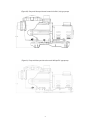
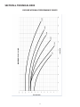
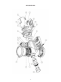
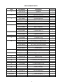
OW N E R ’S MA NUAL - BX and C T X PUMP S
IMPORTANT SAFETY INSTRUCTIONS - READ AND FOLLOW ALL INSTRUCTIONS
SAVE THESE INSTRUCTIONS
Table of Contents
SECTION 1 - SAFETY INSTRUCTIONS........................................................ .......................................................... 2
SECTION 2 - INSTALLATION.................................................................................................................................... 3
SECTION 3 - MAINTENANCE .................................................................................................................................. 5
SECTION 4 - RESTART INSTRUCTIONS ............................................................................................................... 8
SECTION 5 - TROUBLESHOOTING........................................................................................................................ 9
SECTION 6 - TECHNICAL DATA ............................................................................................................................ 10
This manual contains important information about the installation, operation and safe use of this product. This information should be
given to the owner/operator of this equipment.
WARNING
Before installing this product, read and follow all warning notices and instructions accompanying this pump. Failure to follow
safety warnings and instructions can result in severe injury, death, or property damage. Call (904) 378-0999 for additional free
copies of these instructions.
RISK OF ELECTRICAL SHOCK OR ELECTROCUTION
This pool pump must be installed by a licensed or certified electrician or a qualified pool installer in accordance with the latest
edition of the National Electrical Code, NFPA 70 (“NEC”) and/or all applicable local and state codes and ordinances. Installations
in Canada must be in accordance with the latest edition of CSA C22.1 - the Canadian Electric Code, part 1 (“CEC”).
Improper installation could cause an electrical hazard which may result in death or serious injury to pool users, installers, or
others due to electrical shock, and/or property damage. Always disconnect power to the pool pump at the circuit breaker
before servicing the pump. Failure to do so could result in death or serious injury to pool users, installers or others. To reduce
the risk of injury, do not permit children to use this product unless they are closely supervised at all times.
CAUTION
This pump is for use with permanently installed pools and may also be used with hot tubs and spas if so marked. Do not use
with storable pools, do not install within an outer enclosure or beneath the skirt of a hot tub or spa unless so marked.
FLUIDRA USA
8525 Mallory Road, Jacksonville, FL 32220 USA
Phone: (940) 378-0999 • Fax: (904) 378-0408
[email protected] • [email protected]
www.fluidra.us
1
SECTION 1. SAFETY INSTRUCTIONS
GENERAL
When you receive the pump, check the carton for damage. Open the carton and check the pump for concealed
damage, such as cracks, dents, or a bent base. If you find damage, contact the shipper or the distributor where the
pump was purchased.
The pump must be placed on a solid foundation that will not vibrate and Fluidra USA recommends bolting the
pump to the foundation and providing for adequate drainage should any leaks develope.
SUPPLY WIRE SIZES (AWG)
Size and length based on horse power
BX
CTX
115 volts
230 volts
50 ft.
100 ft.
150 ft.
50 ft.
100 ft.
150 ft.
½
¾
14
12
10
14
14
14
¾
1
12
12
10
14
14
14
1
1.5
12
10
8
14
14
14
1.5
2
10
10
8
14
14
12
2
2.5
10
8
8
14
12
12
3
-
-
-
-
12
12
10
Table 1
ELECTRICAL
All electrical work must be performed by a licensed electrician and conform to all national, state, and local codes.
When installing and using this electrical equipment, basic safety precautions should always be followed, including the
following:
The correct voltage and frequency as specified on the pump data plate is necessary for proper performance and
long motor life. Make sure that the wiring specification meets or exceeds the motor requirements (230v or 115v),
see the Table 1 (above) for recommendations.
1. When in doubt, use a heavier gauge (larger diameter) wire which helps the motor to run cooler and more
efficiently.
2. Make sure all electrical connections are clean and tight.
3. Cut wires to the appropriate length so they don’t overlap or touch when connected to the terminal board, and
insulate all connections carefully to prevent grounding or short circuits.
4. Permanently ground the motor using the green ground terminal located on the inside of the motor canopy,
under access plate.
5. Use the correct wire size and type specified by National Electrical Code, “NEC” (or Canadian Electric Code, “CEC”,
for Canada). Make sure the ground wire is connected to an electrical service ground.
6. Electrically bond the motor to the pool structure in accordance with the National Electrical Code (or Canadian
Electric Code for Canada). Use a solid No. 8 AWG or larger copper conductor.
7. Additonally, run a wire from the external bonding point to the pool bonding structure following the NEC/CEC.
8. Connect the pump to a permanent/dedicated circuit. Make sure no other lights or appliances are on the same
circuit.
WARNING
Make sure all electrical breakers and switches are turned off before wiring motor.
2
SECTION 2. INSTALLATION
Proper ventilation is required for the pump to operate normally. Provide access for future service by leaving a clear
area around the pump. Allow plenty of space above the pump to remove the lid and basket for cleaning.
Replacement of an Existing Pump:
BX and CTX pumps can easily replace several other pumps including, Pentair® WhisperFlo® and Sta-Rite Max E Pro®. To
replace the Pentair® WhisperFlo®, or Max E Pro®, use the BX or CTX universal base. The base increases the total height
of the pump and the height of the suction side of the pump. (WhisperFlo® and Sta-Rite Max E Pro® are registered
trademarks of Pentair® Water Pool and Spa, Inc.) See Figure 2.
(Figure 2) BTX-CTX HEIGHT ADJUSTABLE BASE
Installation of Astral BTX-CTX Pump Base (See Figs 3a-3c):
1. The base easily mates up to the BTX or CTX pump.
a. Select the correct side of pump base for desired pump inlet elevation, without base the pump inlet
centerline (fig 3a) is 8.465 in. The base additionally allows for a 9.125 or 10.75 inch pump inlet centerline
to ground clearance --which allows easy retrofits from popular competitor pump products.
b. Align pump foot over mating features on adjustable base after selecting correct base side (from step 1a)
which allows for closely matching existing pump installation’s inlet centerline.
c. Apply moderate down pressure to pump foot to snap pump into base clips, locking it in place.
(Figure 3a) Pump shown without adjustable base
3
(Figure 3b) Pump with base positioned to match Sta-Rite® (tm) type pumps
(Figure 3c) Pump with base positioned to match WhisperFlo® type pumps
4
SECTION 3. MAINTENANCE
WARNING
DO NOT open the strainer pot if pump fails to prime, or if pump has been operating without water in the strainer
pot. Pumps operated in these circumstances may experience a buildup of vapor pressure and may contain
scalding hot water. Opening the pump may cause serious personal injury. In order to avoid the possibility of
personal injury, make sure the suction and discharge valves are open and strainer pot temperature is cool to
touch, then open with extreme caution.
THE FILTER OPERATES UNDER HIGH PRESSURE
When any part of the circulating system (e.g., lock ring, pump, filter, valves, etc.) is serviced, air
can enter the system and become pressurized. Pressurized air can cause the lid to blow off which
can result in severe injury, death or property damage. To avoid this potential hazard, follow these
instructions carefully.
CAUTION
To prevent damage to the pump and filter and for proper operation of the system, clean pump strainer and
skimmer baskets regularly.
THE PUMP STRAINER BASKET
The Pump Strainer Basket, sometimes referred as the “hair and lint pot,” is the unit in front of the volute. Inside the
chamber is the basket which must be kept clean of leaves and debris at all times. View the basket through the ‘See
Through Lid’ to inspect for leaves.
Regardless of the length of time between filter cleaning, it is most important to visually inspect the hair and lint
pot basket at least once a week. A dirty basket will reduce the efficiency of the filter and heater and also put an
abnormal stress on the pump motor which would result in a costly repair bill.
PUMP STRAINER BASKET CLEANING PROCEDURE
1. Turn off motor.
2. Relieve pressure in the system by allowing the water to cool.
3. Gently tap the clamp in a counter-clockwise direction to remove the clamp and lid.
4. Put the debris from the basket into the trash and rinse out the basket. If the basket is cracked, it should be
replaced.
5. Replace the basket and fill the pump pot and volute up to the inlet port with water.
6. Clean the cover, cover O-ring, and sealing surface of the pump pot. Grease the O-ring with Teflon or silicone
grease. NEVER USE PETROLEUM BASED GREASE AS THEY DEGRADE THE O-RINGS.
7. Reinstall the lid by placing the clamp and the lid on the pot; see Exploded View (pg 12) for reference. Make sure
the lid O-ring is properly placed. Seat the clamp and lid then turn clockwise until the handles are perpendicular
to the inlet/outlet ports.
8. Turn the power “ON” at the house circuit breaker. Reset the pool timer clock to the correct time.
9. Open the High Flow manual air relief valve on top of the filter.
10. Start the pump, while standing clear from the filter
11. Bleed air from the filter until a steady stream of water comes out. Close the High Flow manual air relief valve.
5
WINTERIZING
1. If the air temperature drops below 35° F., the water in the pump can freeze and cause damage. Freeze damage
is not warrantable.
2. To prevent freeze damage follow the procedures listed below:
a. Shut off electrical power for the pump at the house circuit breaker.
b. Drain the water out of the pump case by removing the two thumb-twist drain plugs from the case. Store
the plugs in the pump basket to prevent losing them.
c. Cover the motor to protect it from severe rain, snow and ice.
CARE OF THE ELECTRIC MOTOR
1. Protect motor from excess heat
a. Shade the motor from the sun
b. Any enclosure must be well ventilated to prevent overheating
c. Provide ample cross ventilation
2. Protect motor from excess dirt and debris
a. Protect from any foreign matter or splashing water
b. Do not store (or spill) pool chemicals near the motor
c. Avoid sweeping or stirring up dust near the motor while it is operating
d. If a motor has been damaged by dirt it voids the motor warranty
3. Protect motor against excess moisture
a. Protect from splashing pool water
b. Protect from the weather
c. Protect from lawn sprinklers
d. If a motor has become wet - let it dry before operating
Do not allow the pump to operate if it has been flooded
e. If a motor has been damaged by water it voids the motor warranty
NOTE: DO NOT wrap motor with plastic or other air tight materials. The motor may be covered during a storm, or
for winter storage, etc., but never when operating, or expecting operation.
NOTE: When replacing the motor, be certain that the motor support is correctly positioned to support the size of
motor being installed.
WARNING
DO NOT open the strainer pot if pump fails to prime, or if pump has been operating without water in the strainer
pot. Pumps operated in these circumstances may experience a buildup of vapor pressure and may contain
scalding hot water. Opening the pump may cause serious personal injury. In order to avoid the possibility of
personal injury, make sure the suction and discharge valves are open and strainer pot temperature is cool to
touch, then open with extreme caution.
6
PUMP DISASSEMBLY
1. All moving parts are located in the rear sub-assembly of this pump. Tools required:
a. 3/16 inch Allen head wrench.
b. 1/2 inch open end wrench.
c. 1/2 inch open end wrench or socket.
d. Flat blade screwdriver or ¼ inch nut driver to remove motor cap.
e. Phillips screwdriver
2. To remove and repair the motor sub-assembly perform the following procedures.
a. Turn off the pump circuit breaker at the main panel.
b. Drain the pump by removing the drain plugs.
c. Remove the 6 bolts that hold the main pump body (strainer pot/volute) to the rear sub-assembly.
d. GENTLY pull the two pump halves apart, removing the rear sub-assembly.
e. Use a Phillips head screw driver to loosen the two holding screws located on the diffuser.
f. Remove the shaft cap located at the back of the motor and hold the shaft secure with a ½ inch open- end
wrench.
g. Hold the impeller securely in place and remove the impeller lock screw by using a 3/16 inch Allen head
wrench. The screw is a left-handed thread and loosens in a clockwise direction.
h. To unscrew the impeller from the shaft, twist the impeller counter-clock wise.
i. Remove the four bolts from the seal plate to the motor, using a 1/2 inch wrench.
j. If replacing the mechanical seal set, see Sect. B. “Pump Reassembly/Seal Replacement” on next page.
PUMP REASSEMBLY AND SEAL REPLACEMENT
1. When installing the replacement shaft seal, use a light density soap and water to seal the seal. Press the seal
into the seal plate with your thumbs and wipe off the ceramic and carbon faces with a clean cloth, and ensure
the seal is fully seated. See Figure 4.
2. Before installing the ceramic section of the seal into the impeller, be sure the impeller is clean. Use a light
density soap and water to seal the seal. Press the seal into the impeller with your thumbs and wipe off the
ceramic and carbon faces with a clean cloth.
3. Remount the seal plate to the motor by installing bolts in an X pattern while tightening them.
4. Clean the motor shaft thread and the impeller insert, then screw the impeller onto the motor shaft.
5. Screw in the impeller lock screw (counter-clockwise and tighten while holding the motor shaft with wrench).
6. Remount the diffuser onto the seal plate. Make sure the plastic pins and holding screw inserts are aligned.
7. Grease (with a non petroleum-based grease) the diffuser O-ring and seal plate gasket using silicon grease.
NEVER USE PETROLEUM BASED GREASE AS IT DEGRADES O-RINGS AND SEALS.
8. Grease (with a non petroleum-based grease) the bolt threads. Assemble the motor sub-assembly to the strainer
pot pump body by using the two through bolts for proper alignment. Do not tighten the through bolts until all
6 bolts are in place and finger tightened first. When tightening, alternate torqueing of bolts using an X-pattern
to maintain even tightening.
9. Fill the pump with water.
7
THE SHAFT SEAL (MECHANICAL SEAL)
1. The Shaft Seal consists primarily of two parts, a rotating member and a ceramic seal. See Figure 4.
2. The pump requires little or no service other than reasonable care, however, a Shaft Seal may occasionally
become damaged and must be replaced.
(Figure 4)
Shown with motor removed, for clarity (see Exploded View pg 12 for
additional detail)
NOTE:
It is important that the O-rings be kept clean and well lubricated.
We recommend a silicone based lubricant for best results. DO NOT
USE PETROLEUM-BASED GREASE ON SEALS OR O-RINGS.
SECTION 4. RESTART INSTRUCTIONS
If pump is installed below the water level of the pool, close return and suction lines prior to opening hair and lint pot
on pump. Make sure to re-open valves prior to operating.
NOTE: Continued operation in this manner could cause a loss of pressure, resulting in damage to the pump case,
impeller and seal.
PRIMING THE PUMP
NOTE: The pump strainer pot must be filled with water before the pump is initially started.
Follow these steps to prime the pump:
1. Remove the pump lid plastic clamp. Remove the pump lid.
2. Fill the pump strainer pot with water.
3. Reassemble the pump cover and plastic clamp onto the strainer pot. The pump is now ready to prime.
4. Open the air release valve on the filter, and stand clear of the filter.
5. Turn on the switch or time clock.
6. When water comes out of the air release valve, close the valve. The system should now be free of air and recirculating water to and from the pool.
For 2-speed pumps:
1. Pump should run on high-speed for priming.
2. The pump should not run longer than 8 minutes before priming is achieved.
8
SECTION 5. TROUBLESHOOTING
FAILURE TO PUMP
Pump will not prime - too much air. Remedy:
1. Check suction piping and valve glands on any suction gate valves
2. Secure lid on pump strainer pot and make sure lid gasket is in place
3. Check water level to make sure skimmer is not drawing air
Pump will not prime - not enough water. Remedy:
1. Make sure suction lines, pump strainer, and pump volute are full of water
2. Make sure valve on suction line is working and open, (some systems do not have valves)
3. Check water level to make sure water is available through skimmer
Pump strainer clogged. Remedy:
1. Clean pump strainer pot
Pump strainer gasket defective. Remedy:
1. Replace gasket
REDUCED CAPACITY AND/OR HEAD
Air pockets or leaks in suction line. Remedy:
1. See item “Pump will not prime - too much air” of this section, above
Clogged impeller. Remedy:
1. Disassemble per SECTION III “Pump Disassembly”
2. Clean debris from impeller. If debris cannot be removed, complete the following steps:
a. Remove left hand thread anti-spin bolt and O-ring
b. Remove, clean and reinstall impeller
3. Reassemble per SECTION III “Pump Reassembly”
Pump strainer clogged. Remedy:
1. Clean suction trap
9
SECTION 6. TECHNICAL DATA
BX PUMP HYDRAULIC PERFORMANCE CURVES
10
CTX PUMP HYDRAULIC PERFORMANCE CURVES
11
EXPLODED VIEW
12
REPLACEMENT PARTS
Code
Part Number
Description
Quantity
1
53977-78736
53976-78735
53977-78106
53976-70006
53977-40086
53976-40087
53977-40068
53976-40088
53977-950925
53977-950924
53976-950920
53976-950918
53977-950926
53976-950919
53976-78737
53976-70003
53976-78104
53976-4008101
53976-4008102
53976-4008103
53976-4008104
53976-4008105
53976-78720
53976-78721
53977-40066
53976-40065
53976-78104
53976-4005002
53976-40056
53976-40111
53976-70004
BX Volute
CTX Volute
BX Pump Lid O-ring
CTX Pump Lid O-ring
BX Pump Clear Lid
CTX Pump Clear Lid
BX Pump Lid Collar
CTX Pump Lid Collar
BX 2” Union Tail
BX 1.5” Union Tail
CTX Union Tail (2”)
CTX Union Tail (1.5”)
BX Union Lock Nut
CTX Union Lock Nut
CTX/BX Seal Plate
CTX Union O-ring
BX Union O-ring
BX ( 0.75HP) CTX (1.0HP) Impeller
BX ( 1.0HP) CTX (1.5HP) Impeller
BX ( 1.5HP) CTX (2.0HP) Impeller
BX ( 2.0HP) CTX (2.5HP) Impeller
Impeller 3.0HP
Diffuser 0.5HP - 2.5HP
Diffuser 3.0HP
BX Pump Basket
CTX Pump Basket
Diffuser O-ring
CTX/BX Molded Motor Foot
CTX/BX Motor Foot Rubber Mount
5/16” UNC bolt HEX SS
CTX/BX Seal Plate O-ring
Drain Plug
Option 3” adapter
Optional Universal Base
3/8” UNC bolt HEX SS
Mechanical Seal 3/4”
Screw self-tap SS
CTX 5/16-2.25” UNC HEX SS
1
1
1
1
1
1
1
1
2
2
2
2
2
2
1
2
2
1
1
1
1
1
1
1
1
1
1
1
1
6 and 4
1
2
2
1
4
1
2
2
2
3
4
5
6
7
8
10
11
13
14
15
16
17
18
19
20
21
22
Not Shown
Not Shown
Not Shown
53976-40110
53976-75508
53976-40165
53976-40112
13
WARRANTY
AstralPool manufactures its products with the highest standards of workmanship, using the best materials available
through state of the art processes. AstralPool warrants its products as follows:
LIMITED WARRANTY: ASTRALPOOL WARRANTS ITS PRODUCTS TO BE FREE FROM DEFECTS IN MATERIAL
AND/OR WORKMANSHIP FOR A PERIOD OF ONE (1) YEAR (PARTS ONLY) FROM THE ORIGINAL DATE OF
PURCHASE OR INSTALLATION.
SPECIFIC PRODUCT WARRANTIES (FROM DATE OF INSTALLATION):
PRODUCT
LIMITED
WARRANTY
EXCEPTIONS
BX Pump Line
2 year
Excludes Motor Bearings/O Rings-Gaskets/Seals-*(1) System Warranty 3 year
CTX Pump Line
2 year
Excludes Motor Bearings/O Rings-Gaskets/Seals
* (1) - Viron Builder Extended System Warranty - Must install a minimum of two Viron products- includes 1 year in field labor
Exceptions that could result in denial of a warranty claim:
1. Damage caused by careless handling, improper repackaging, or shipping.
2. Damage due to misapplication, misuse, abuse or failure to operate equipment as specified in the owners
manual.
3. Damage caused by failure to install products as specified in the owners manual.
4. Damage due to unauthorized product modifications or failure to use AstralPool original replacement parts.
5. Damage caused by negligence, or failure to properly maintain products as specified in the owners manual.
6. Damage caused by failure to maintain water chemistry in conformity with the standards of the swimming
pool industry for any length of time.
7. Damage caused by water freezing inside the product.
8. Accidental damage, fire, acts of God, or other circumstances outside the control of AstralPool.
WARRANTY OBLIGATIONS OF ASTRALPOOL
Should a defect in workmanship and/or material in any item covered by this warranty become evident during the
term of the warranty, then upon the consumer following the procedures set forth below, AstralPool will, at its option,
repair or replace such item or part at its own cost and expense.
AstralPool is not, however, responsible under this warranty for any cost of shipping or transportation of the equipment
or parts thereof to or from the Technical Service Department. Also, AstralPool is not liable for any loss of time,
inconvenience, incidental expenses such as telephone calls, labor or material charges incurred in connection with the
removal or replacement of the equipment, or any other incidental or consequential damages.
This warranty is void if the product is repaired or altered in any way by any persons, agents or representatives other
than those authorized by AstralPool. Expendables including, but not limited to refrigerant, recovery of refrigerant, or
transportation for components are not covered under this limited warranty. Reasonable vehicle trip and evaluation
charges may be assessed by the service representative. AstralPool, at its sole discretion, reserves the right to provide a
replacement product or part, of equal value, in lieu of repair.
Some states do not allow the exclusion or limitation of incidental or consequential damages, so the above limitation
or exclusion may not apply to you.
Except as stated in this section, AstralPool, its subsidiaries and affiliates make no warranties, express, implied or
statutory, as to any matter whatsoever. In particular, any and all warranties of merchantability or fitness for a particular
purpose and noninfringement of third party rights are expressly excluded.
14
PROCEDURE FOR OBTAINING RETURN GOODS AUTHORIZATION
In order to obtain the benefits of this warranty, the consumer who made the original retail purchase must contact
the AstralPool Technical Service Department as soon as possible after discovery of the defect, but in no event later
than the expiration date of the warranty period provided in this warranty. Upon receipt of this communication,
AstralPool will promptly notify the customer of the address to which the defective item may be shipped. The
customer shall then ship the item, freight prepaid by customer, to the address indicated, together with a “RETURN
GOODS AUTHORIZATION” form obtained from Technical Service and a brief description of the problems encountered.
Unauthorized returns will not be accepted. Freight must be prepaid by customer.
WARRANTIES OR REPRESENTATIONS BY OTHERS
No dealer or other person has any authority to make any warranties or representation concerning AstralPool or its
products. Accordingly, AstralPool is not responsible for any such warranties or representations.
SOLE WARRANTY
Supersedes all previous publications.
15
OWNER’S MANUAL
USA
8525 Mallory Road, Jacksonville, FL 32220 USA
Phone: (940) 378-0999 • Fax: (904) 378-0408
[email protected] • [email protected]
www.fluidra.us
16