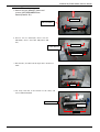
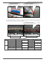
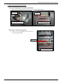
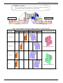
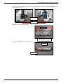
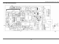
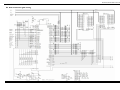
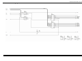
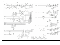
1
Service Manual
LINE THERMAL PRINTER
MODEL PMU-2200II / 2300II
Rev. 1.00 Issued on January 19, 2009
PMU2XXX Service Manual
REVISION
Rev.
Date
1.00
2009/1/19
Page
Comment
Newly issued
CITIZEN is a registered trade mark of CITIZEN HOLDINGS CO., LTD., Japan.
CITIZEN es una marca registrada de CITIZEN HOLDINGS CO., LTD., Japón.
-1-
PMU2XXX Service Manual
CONTENTS
INTRODUCTION.......................................................................................................................................3
1. DISASSEMBLY AND REASSEMBLY...............................................................................................3
1.1 Tools Used.........................................................................................................................................3
1.2 Disassembly Procedure ...................................................................................................................4
1.2.1 Removing Board Main...............................................................................................................4
1.2.2 Removing UNIT,MECHANISM ..................................................................................................5
1.2.3 Removing UNIT, Paper Holder ..............................................................................................10
1.2.4 Removeng BM Sensor.............................................................................................................16
1.2.5 Removeng SA PLATEN HILDER.............................................................................................18
2. Memory Switch Setting.................................................................................................................19
3. TROUBLESHOOTING ......................................................................................................................20
3.1 Error Indication...............................................................................................................................20
3.2 Troubleshooting Procedure...........................................................................................................22
3.3 Troubleshooting Guide ..................................................................................................................22
4. SERVICE PARTS LIST .....................................................................................................................26
4.1 Parts List for Mechanism...............................................................................................................26
4.2 Exploded View of Mechanism.......................................................................................................29
4.2.1 PMU2220Ⅱ/2210Ⅱ 2-inch mode Base style:Horizontal ...........................................29
4.2.2 PMU2211Ⅱ 2-inch mode Base style:Vertical front-mount ..........................................30
4.2.3 PMU2202Ⅱ/2212Ⅱ 2-inch mode Base style:Vertical back-mount ............................31
4.2.4 PMU2300Ⅱ/2310Ⅱ 3-inch mode Base style:Horizontal..............................................32
4.2.5 PMU2301Ⅱ 3-inch mode Base style:Vertical front-mount ..........................................33
4.2.6 PMU2302Ⅱ 3-inch mode Base style:Vertical back-mount ..........................................34
4.3 List of Electric Parts .......................................................................................................................35
4.4 Parts Configuration ........................................................................................................................36
4.4.1 Main Control Board(Serial).....................................................................................................36
4.4.2 Main Control Board(Parallel)..................................................................................................37
4.4.3 Main Control Board(USB) .......................................................................................................38
4.4.4 Main Control Board(USB) .......................................................................................................39
5. CIRCUIT DIAGRAM .........................................................................................................................40
5.1 Main Control Board(CPU Circuit).............................................................................................40
5.2 Main Control Board(port) .........................................................................................................41
5.3 Main Control Board(Other Common part) .............................................................................42
5.4 Main Control Board(Interface Circuit on Serial, USB)..........................................................43
5.5 Main Control Board(Interface Circuit on Serial, Parallel) ....................................................44
-2-
PMU2200Ⅱ/2300ⅡSERIES Service Manual
INTRODUCTION
This manual describes the disassembly, reassembly, and maintenance procedures of the KIOSK printer
PMU2XXX
1. DISASSEMBLY AND REASSEMBLY
Notes the following items when maintaining the printer.
• Do not disassemble, reassemble, or adjust the printer unnecessarily when the printer operation is
satisfactory.
• Do not loosen the screws fixing each component carelessly.
• After finishing inspection, perform checking for normality before turning on the printer.
• Pay attention not to leave the part or screws used for maintenance inside the printer.
• When handling the print head and electronic components, pay attention to static electricity.
• When disassembling or reassembling the printer, check the wiring and cord for damage. Pay attention not
to lay the wiring and cord by force.
• Lubricate the components as necessary when reassembling them.
1.1 Tools Used
•
•
•
•
Phillips screwdriver #0, #1, and #2
Tweezers
Long-nose pliers
Nipper
-3-
PMU2200Ⅱ/2300ⅡSERIES Service Manual
1.2 Disassembly Procedure
1.2.1 Removing Board Main
1. Removing Cover IF Board
1. Remove M3x6(ST) Screw.
2. Remove Cover IF Board.
Hook
*Attention at reassembly
Insert Cover IF Board up to the hooks.
Cover IF Board
M3x6 (ST)
2. Removing UNIT, Guide Paper Rear)
1. Remove the two M3x6(ST) Screw 、 and UNIT,
Guide Paper Rear.
M3x6 (ST)
UNIT,
Guide Paper Rear
3. Removeng Board Main
1. Remove cable and FPC from Main PCB.
CN102
CN108
Release the lock of
CN107 before
remove FPC.
CN104
CN109
CN103
CN107
CN106
CN107
-4-
PMU2200Ⅱ/2300ⅡSERIES Service Manual
2. Remove the four M3x6(ST) Screw、and Board Main.
M3x6 (ST)
Board Main
*Attention at reassembly
Note the direction of FPC (CN102).
*Attention at reassembly
Note the direction of
FPC(CN107).
1.2.2 Removing UNIT,MECHANISM
1. Removeng AUT CUTTER
1. Remove the four M3x6(ST thin head)Screw from the side.
2. Widen Cutter BK(Cutter BK 2in) a little, remove ,AUT CUTTER.
* Do not transform Cutter BK(Cutter BK 2in) by expanding it in excess.
Cutter BK
Cutter BK 2in
AUT CUTTER
M3x6(ST thin head)
Hook
*Attention at reassembly
Hang the cable of AUT CUTTER on
the hooks.
Hook
-5-
PMU2200Ⅱ/2300ⅡSERIES Service Manual
2. Removeng UNIT,MECHANISM
1. Remove the two M3x6(ST) Screw and
remove UNIT,MECHANISM from
Frame1(Frame1 2in).
M3x6 (ST)
UNIT,
MECHANISM
Hook
2. Remove the two M3x6(ST) Screw and two
M2x6(BT) Screw and.Cutter BK(Cutter BK
2in).
Cutter BK
(Cutter BK 2in)
M3x6(ST)
M2x6 (BT)
3. Pull out FPC, and Peel off the Tape that is fixation of
cable.
Tape
4. Cut Unity belt that is the fixation of the cable, and
remove MECHANISM.
MECHANISM
Unity belt
Hook
-6-
PMU2200Ⅱ/2300ⅡSERIES Service Manual
*Attention at reassembly
Note the direction of FPC.
*Attention at reassembly
Hang the cable of motor on the hooks.
*Note that the MECHANISM C is different by PMU2200/2300 SERIES and PMU2200Ⅱ/2300ⅡSERIES.
Even if externals are the same, they are not compatible.
*Attention at reassembly
The color of the coating is a black..
PMU2200Ⅱ/2300ⅡSERIES
PMU2200/2300 SERIES
2-in
3-in
Model
Horizontal
58mm
Horizontal
60mm
Vertical Front 60mm
Vertical Back 58mm
Vertical Back 60mm
Horizontal
60mm
Horizontal
80mm
Vertical Front 80mm
Vertical Back 80mm
Table MECHANISM
PMU2200/2300 SERIES
PMU2200(A)
LT-2223V(A)
PMU2210(A)
PMU2211(A)
LT-2223H(A)
PMU2202(A)
LT-2223V(A)
PMU2212(A)
PMU2310(A)
LT-2321V(A)
PMU2300(A)
PMU2301(A)
LT-2321H(A)
PMU2302(A)
LT-2321V(A)
-7-
PMU2200Ⅱ/2300Ⅱ SERIES
PMU2200Ⅱ(A)
LT-2223VQ(A)
PMU2210Ⅱ(A)
PMU2211Ⅱ(A)
LT-2223HQ(A)
PMU2202Ⅱ(A)
LT-2223VQ(A)
PMU2212Ⅱ(A)
PMU2310Ⅱ(A)
LT-2321VQ(A)
PMU2300Ⅱ(A)
PMU2301Ⅱ(A)
LT-2321HQ(A)
PMU2302Ⅱ(A)
LT-2321VQ(A)
* A: Thick paper
PMU2200Ⅱ/2300ⅡSERIES Service Manual
3. Removeng SA,Spring Paper Roller
Base style: Horizontal / Vertical back-mount
1. Remove the two M3x8(ST) Screw and remove SA, Spring Paper Roller.
M3x6(ST)
M3x6(ST)
SA, Spring Paper Roller
SA, Spring Paper Roller
Base style: Vertical front-mount
1. Remove the two M3x4(ST) Screw and remove
SA, Spring Paper Roller.
M3x4(ST)
SA, Spring Paper Roller
-8-
PMU2200Ⅱ/2300ⅡSERIES Service Manual
4. Removeng Guide Paper Rear
1. Remove the two M3x6(ST) Screw and remove Guide Paper Rear(Guide Paper Rear 58 2in / Guide
Paper Rear 60 2in).
M3x6(ST)
SA, Spring Paper Roller
Guide Paper Rear
(Guide Paper Rear 58 2in)
(Guide Paper Rear 60 2in)
*3-in is all common. 2-in becomes the following.
Table 2-in Guide Paper Rear
Model
Horizontal 58mm PMU2200Ⅱ
Horizontal 60mm PMU2210Ⅱ
Vertical Front 60mm PMU2211Ⅱ
Vertical Back 58mm PMU2202Ⅱ
Vertical Back 60mm PMU2212Ⅱ
Guide Paper Rear
Guide Paper Rear 58 2in
Guide Paper Rear 60 2in
-
Guide Paper Rear 58 2in
Guide Paper Rear 60 2in
5. Removeng Guide 2inch(3inch-model:PMU2310)
1. Remove the two M3x6(ST) Screw.
M3x6(ST)
Guide 2inch
2. Remove Guide 2inch while floating it from the
hook.
Hook
-9-
PMU2200Ⅱ/2300ⅡSERIES Service Manual
1.2.3 Removing UNIT, Paper Holder
1. Removeng SA Plate Paper Holder
Insert from left / Insert from right
1. Plate Paper Holder:Remove the two M3x6(ST) Screw.
M3x6 (ST)
M3x6 (ST)
2. Stopper Paper Plate:Remove M3x6(ST)Screw and WASHER,Nut M3.
M3x6 (ST)
WASHER
Nut M3
Insert from top
1. Plate Paper Holder:Remove the four M3x6(ST) in right and left.
M3x6 (ST)
M3x6 (ST)
M3x6 (ST)
M3x6 (ST)
Attention at 2-inch model
*Attention at reassembly
There are two kinds of Plate Paper Holder for
2-inch model.It is different depending on the
specification.
Plate Paper Holder 2in
-10-
Plate Paper Holder2 2in
PMU2200Ⅱ/2300ⅡSERIES Service Manual
*Attention at reassembly
The screw position and the direction of Plate Paper Holder and Stopper
Paper Plate are different depending on the specification.
(3)
(1)
(2) (1)
Left side
(2) (3)
Right side
Table Paper diameter ( Direction of paper insertion L: Insert from left )
Left side
Right side
Holder
2-in Holder
position
(3)
(2)
(1)
(1)
(2)
(3)
(*3in is all the same.)
1: A bit near
-
2: Standard
-
-
-
-
3: A bit far
-
-
4: Far
-
-
-
Plate Paper Holder2 2in
-
-
Plate Paper Holder 2in
*It becomes an installation in the direction of figure in the table.
-11-
PMU2200Ⅱ/2300ⅡSERIES Service Manual
(3)
(1)
(2) (1)
Left side
(2) (3)
Right side
Table Paper diameter ( Direction of paper insertion R: Insert from right)
Left side
Right side
Holder
2-in Holder
position
(3)
(2)
(1)
(1)
(2)
(3)
(*3in is all the same.)
1: A bit near
-
-
2: Standard
3: A bit far
4: Far
-
-
-
-
-
-
-
-
Plate Paper Holder 2in
-
-
Plate Paper Holder2 2in
*It becomes an installation in the direction of figure in the table.
-12-
PMU2200Ⅱ/2300ⅡSERIES Service Manual
(3)
(1)
(2) (1)
Left side
Table
Holder
position
1: A bit near
(2) (3)
Right side
Paper diameter ( Direction of paper insertion T: Insert from top)
Left side
Right side
2-in Holder
(3)
(2)
(1)
(1)
(2)
(3)
(*3in is all the same.)
Left side:
-
-
Plate Paper Holder 2in
Right side:
-
2: Standard
-
Plate Paper Holder2 2in
Left side:
3: A bit far
-
-
Plate Paper Holder2 2in
Right side:
4: Far
-
-
Plate Paper Holder 2in
*It becomes an installation in the direction of figure in the table.
-13-
PMU2200Ⅱ/2300ⅡSERIES Service Manual
*E-Ring 5 position A is different according to Direction of paper insertion.
(1)
(2)
Shaft Paper Holder 2in
Table
Model
Horizontal 58mm
Horizontal 60mm
Vertical Front 60mm
Vertical Back 58mm
Vertical Back 60mm
2-in Model E-Ring 5 position
E-Ring 5 position
Left
Right
Top
PMU2200Ⅱ
(1)
PMU2210Ⅱ
(2)
-
PMU2211Ⅱ
PMU2202Ⅱ
(1)
PMU2212Ⅱ
(2)
(1)
(2) (3)
(4)
Shaft Paper Holder
3-in Model E-Ring 5 position
E-Ring 5 position
Left
Right
Top
PMU2310Ⅱ
(2)
(1)(4)
(3)
PMU2300Ⅱ
(4)
-
PMU2301Ⅱ
PMU2302Ⅱ
Table
Model
Horizontal 60mm
Horizontal 80mm
Vertical Front 80mm
Vertical Back 80mm
-14-
PMU2200Ⅱ/2300ⅡSERIES Service Manual
2. Removeng PNE Sensor
Insert from left/Insert from right
Shaft Paper Holder
1. Remove M4x6(ST) Screw.
Paper Holder
*Attention at reassembly
Put Plate Paper Holder and SA PNE Sensor between
Shaft Paper Holder, and stop it with the screw.
Installed position is different depending on the
specification.
6: 60mm
8: 80mm
PNE Sensor
M4x6(ST)
1: 102mm
Insert from top
1. Remove M3x3(ST) Screw.
*Attention at reassembly
Put Plate Paper Holder and SA PNE Sensor
between Shaft Paper Holder, and stop it with
the screw.
M3x3(ST)
*Attention at reassembly
The cable is passed through the hole
*Attention at reassembly
Connect BM Sensor with CN108 of
Borad Main do not make a mistake
because CN108 and CN109 are
connectors of this type.
-15-
CN108
PMU2200Ⅱ/2300ⅡSERIES Service Manual
1.2.4 Removeng BM Sensor
Base style: Horizontal / Vertical back-mount
Position M1
Position M2
Position M1
Position M2
1. Remove M3x6(ST) Screw.
Position M1
Position M2
*Attention at reassembly
The screw hole is different because o f
Position.
Fix the hole for projection on Projection
for fixation.
Screw hole
for M1
M4x6 (ST)
Projection
for fixation
Projection
for fixation
*Attention at reassembly
Connect BM Sensor with CN109 of Board
Main. Do not make a mistake because
CN108 and CN109 are connectors of this
type.
-16-
Hole for
projection
CN109
Screw hole
for M1
PMU2200Ⅱ/2300ⅡSERIES Service Manual
Base style: Vertical front-mount
Position M1
Position M2
1. Remove the two M3x6(ST) Screw.
2. Remove SA PNE Sensor.
Position M1
M3x6 (ST)
Position M2
*Attention at reassembly
Connect BM Sensor with CN109 of Board
Main. Do not make a mistake because
CN108 and CN109 are connectors of this
type.
CN109
-17-
PMU2200Ⅱ/2300ⅡSERIES Service Manual
1.2.5 Removeng SA PLATEN HILDER
1. Remove the two M3x6(ST) Screw from the side.And remove Unit SA PLATEN HILDER from
Frame 1(Frame 1 2in).
SA PLATEN
HILDER
M3x6(ST)
2. Remove the two M3x6(BT) Screw.
M3x6(BT)
Holder2 Platen Unit
(Holder2 Platen Unit 2in)
3. Remove M2x4(BT) Screw and Fix Brade
Fix Brade
M2x4(BT)
-18-
PMU2200Ⅱ/2300ⅡSERIES Service Manual
2. Memory Switch Setting
It is registered in the printer as follows by the option of the factory. They are different by the model, and not
possible to change
(1) Printer Name of the self-printing
(2) Printer Name of the self-printing
(3) Initial value
However, the above-mentioned is unrelated to the function it. It is possible to correspond by changing the Memory
Switch.
Base Model
Memory Switch Setting is as follows. If Memory Switch Setting is not correct, the printer doesn't operate
correctly.
Table Base Model
MSW4-5
MSW2-6
Mechanism
Paper width
mounted
Base Model
Horizontal 58mm
Horizontal 60mm
Vertical Front 60mm
Vertical Back 58mm
Vertical Back 60mm
Horizontal 60mm
Horizontal 80mm
Vertical Front 80mm
Vertical Back 80mm
PMU2200Ⅱ
PMU2210Ⅱ
PMU2211Ⅱ
PMU2202Ⅱ
PMU2212Ⅱ
PMU2310Ⅱ
PMU2300Ⅱ
PMU2301Ⅱ
PMU2302Ⅱ
ON
OFF
LT-22XX
LT-23XX
ON
OFF
58(60)mm
80 mm
MSW4-4
Base style
OFF
PMU2XX0/2XX2
ON
PMU2XX1
OFF
PMU2XX0/2XX2
ON
OFF
PMU2XX1
PMU2XX0/2XX2
Destination
Memory Switch Setting is as follows.
Destination
J : Japan
U: US/EU/Other
Table Destination
MSW9-1
MSW9-2
Code Page
Int’Char Set
Katakana
Japan
PC437
U.S.A
MSW9-3
Kanji
ON
OFF
PNE Sensor
Memory Switch Setting is as follows.
Table PNE Sensor
PNE Sensor
No mark
P
: Without sensor
: PNE sensor
MSW2-8
PNE Sensor
ON
Invalid
OFF
Valid
Paper Select
Memory Switch Setting is as follows.
Paper
No mark
M1/M2
: Thermal
: Black MK
-19-
Table Paper Select
MSW3-4
Paper Select
OFF
Thermal
ON
Black MK
MSW4-1
Auto Length
OFF
Invalid
ON
Valid
PMU2200Ⅱ/2300ⅡSERIES Service Manual
3. TROUBLESHOOTING
3.1 Error Indication
z Paper end
Paper out is detected in two steps: paper near-end and paper end. ERROR LED will light when the
paper is empty. If paper end is detected, refill the paper. If the printer cover is open, a paper-end is
detected.
z Printer Platen open
During printing, do not open the platen. If you open the printer cover accidentally, the ERROR
LED blinks. Check the paper, pull the paper straightforward several cm (or inches) out of the
printer, and then close the Platen. Printing resumes automatically. Sending a command to resume
printing may be required depending on the memory switch setting.
z Thermal head overheat
When you print dense characters or dark image, the head temperature rises. If the head temperature
exceeds a specified level, the printer stops printing operation and waits till the head temperature is
lowered. During waiting, the ERROR LED blinks. When the head temperature is lowered, printing
resumes automatically.
z Cutter lock
If the cutter blade stops operating due to paper jam or the like, the ERROR LED blinks. Remove
the cause of the trouble and press the FEED button. If the blade still does not move and the printer
cover cannot be opened.In this case, do not open the paper cover forcibly. Insert a Phillips
screwdriver (size #1) into the cutter lock releasing feed hole and turn it in the direction of arrow
(clockwise).
When you find that both ends of the blade reached the lowest position, stop turning the screwdriver.
Open the cover and follow the procedure of removing jam or other cause of trouble.
-20-
PMU2200Ⅱ/2300ⅡSERIES Service Manual
z Black Mark detection error (in Black Mark mode)
When Black Mark cannot be detected even if a certain amount of paper feed is carried out for
Black mark detection, a Black Mark detection error occurs. If black detection continues more than
the specified period, a No Paper condition is assumed and the same error as No Paper is indicated.
Lighting and blinking status of each error including the above is shown below.
POWER LED
(Green)
Content of Error
1) Error to recover
automatically
2) Recoverable error
[1] Head overheat error
ON
[2] Platen open error
(MSW3-8 OFF: With automatic return set)
ON
[1] Platen open error
(MSW3-8 ON: With recoverable feature set)
ON
[2] Cutter lock error
ON
3) Not recoverable error [1] Memory check error
ON
[2] Low voltage error
ON
[3] High voltage error
4) Other state
ON
[1] Paper near end
[2] Paper end
[3] Platen open
[4] Waiting for macro execution
5) Black mark
specification relation
ERROR LED
(Red)
[1] Black mark paper detection error
ON
ON
ON
ON
ON
ON
ON
ON
Caution: In many cases, “Low voltage error” is caused by blown F302 fuse.Please check the
conduction of F302 fuse.
-21-
PMU2200Ⅱ/2300ⅡSERIES Service Manual
3.2 Troubleshooting Procedure
When a trouble occurs, confirm its phenomenon, locate a defective part in accordance with “2.2
Troubleshooting Guide”, and troubleshoot as described below.
Phenomenon
Find a trouble phenomenon in this column. If there are multiple phenomena, take all the
corresponding items into consideration to locate hidden defective parts.
Cause
Lists as many possible causes as possible. Guess a trouble cause out of them and take
its check method to specify the trouble cause.
Check
Method
Describes a check method to specify a trouble cause.
Remedy
Troubleshoot by taking a remedy described in this column.
By troubleshooting in accordance with the above-mentioned procedure, you can troubleshoot efficiently with
fewer misjudgments.
3.3 Troubleshooting Guide
• Power Supply Failure
Phenomenon
No power
(POWER lamp not
illuminated)
Cause
Check Method
The AC cable is not
connected.
—
The fuse is gone.
Check whether the
specified fuse is used.
The fuse immediately
Faulty control PCB assy
goes again after
replacing with a new one. The circuit drive power is
abnormal.
Remedy
Connect AC cable.
Use the specified fuse.
—
Replace the control PCB
assy.
Use instruments such as
tester to measure circuit
driving voltage.
Replace the control PCB
assy.
* If the fuse is gone with the specified AC adapter used, it is likely that the thermal head unit or control PCB
assy is defective. Replace either defective one. Check wiring for drawer cable and interface cable.
-22-
PMU2200Ⅱ/2300ⅡSERIES Service Manual
• Printing failure
Phenomenon
No printing
Partly not printed
Faint printout or uneven
printout
Cause
Faulty control PCB assy
Check Method
Remedy
—
Replace the control PCB
assy.
Failed contact/connection Check
of thermal head
contact/connection
connector
condition.
Re-insert thermal head
connector.
Faulty thermal head
Replace the thermal
head.
—
Faulty contact/connection Check contact/conection
in thermal head
conditions.
connector
Re-insert thermal head
connector.
Faulty thermal head
Replace the thermal
head.
Low output voltage
—
Check the supply voltage Use within specified
with tester or others.
voltage range.
Faulty thermal head
—
Replace the thermal
head.
Foreign substance is
adhered to the thermal
head.
Check whether any
foreign substances are
adhered to the head.
Non-recommended
paper is used.
Check whether the paper Replace it with the
being used meets the
specified paper.
specification.
Faulty mounting of the
platen roller
Check mounting
condition of the platen
roller.
-23-
Wipe foreign materials
with swab or soft cloth
immersed with ethyl
alcohol.
Mount the platen roller
properly.
PMU2200Ⅱ/2300ⅡSERIES Service Manual
• Paper feed failure
Phenomenon
Paper is not fed or
jammed.
Cause
Check Method
Remedy
Faulty connection of the
motor connector
Check the connector
connection.
Connect the connector
correctly.
Failed motor’s main unit
Use tester or
oscilloscope or other
instrument to measure
supply voltage.
If the supply voltage is
normal, replace the
motor.
Low output voltage
Check the supply voltage Use within specified
with tester or others.
voltage range.
Faulty control PCB assy
—
Replace the control PCB
assy.
Faulty mounting of the
platen roller
Check mounting
condition of the platen
roller.
Paper feed failure
Check that no paper is
Remove unnecessary
jammed, torn or caught in paper and set correctly.
the paper path.
Foreign substance in the
gear or broken gear
Remove the gear holder
and check for any foreign
substance caught in the
gears or any breakage of
the gears.
Eliminate the foreign
substance. If the gear is
broken, replace it with
new one.
Cause
Check Method
Remedy
Mount the platen roller
properly.
• Faulty sensor
Phenomenon
Failed detection of paper
feed
Failed detection of
paper’s near-end
Faulty paper sensor
Check whether the
ERROR LED flickers if
paper expires.
Replace the SA SUB
PWB PE SENSOR.
Foreign substance is
attached to the paper
sensor
Check whether any
foreign substances are
adhered to the paper
sensor.
Remove the foreign
substance.
Faulty connection of the
paper sensor connector
Check the connector
connection.
Connect the connector
correctly.
Faulty paper near-end
sensor
-24-
Replace the SA PNE
SENSOR.
PMU2200Ⅱ/2300ⅡSERIES Service Manual
• Faulty auto cutter
Phenomenon
No operation of
auto-cutter
Cause
Check Method
Remedy
Faulty connection of the
auto cutter connector
Check the connecting
condition of the auto
cutter connector.
Connect the connector
correctly.
Failure in auto-cutter’s
main unit
Use tester or
oscilloscope or other
instrument to measure
supply voltage.
If the supply voltage is
normal, replace the auto
cutter.
Paper feed failure
(Paper jam)
Check that no paper is
Remove unnecessary
jammed, torn or caught in paper and set correctly.
the paper path.
-25-
PMU2200Ⅱ/2300ⅡSERIES Service Manual
4. SERVICE PARTS LIST
4.1 Parts List for Mechanism
No.
PARTS No.
201
202
206
217
PF22‐SQxGx
PF22‐CQxGx
ZF44109-00F
ZF44114-00F
1
2
6
17
PF23‐SQxCx
PF23‐CQxCx
ZF44101-01F
ZF44102-01F
DESCRIPTION
UNIT,MECHANISM
39 ZF67901-00F
40 ZF44116-00F
QTY
2202
2300
2212
2310
2200
2210
2211
LT2223VQ(with Platen assy)
LT2223HQ(with Platen assy)
Cutter BK 2in
Plate Printer 2in
1
0
1
1
0
1
1
1
1
0
1
1
LT2321VQ(with Platen assy)
LT2321HQ(with Platen assy)
Cutter BK
Plate Printer
0
0
0
0
0
0
0
0
FPC
Sheet FFC Support
1
1
REMARKS
2301
2302
0
0
0
0
0
0
0
0
0
0
0
0
2inch
2inch
2inch
2inch
0
0
0
0
1
0
1
1
0
1
1
1
1
0
1
1
3inch
3inch
3inch
3inch
1
1
1
1
1
1
1
1
1
1
2/3inch
2/3inch
204 ACS520
4 ACS530
AUT CUTTER
ACS520 Cutter(with Fix Brade)
ACS530 Cutter(with Fix Brade)
1
0
1
0
1
0
0
1
0
1
0
1
2inch
3inch
209
210
214
221
ZF24201-00F
PF28205-01F
500374-00
ZF44113-01F
SA PLATEN HILDER
Platen Holder 2in
(Platen)
(Fix Brade)
Holder2 Platen Unit 2in
1
1
1
1
1
1
1
1
1
1
1
1
0
0
0
0
0
0
0
0
0
0
0
0
2inch
2inch
2inch
2inch
9
10
14
21
600382-00
PF28206-01
500318-00
ZF44104-01F
Platen Holder
(Platen)
(Fix Brade)
Holder2 Platen Unit
0
0
0
0
0
0
0
0
0
0
0
0
1
1
1
1
1
1
1
1
1
1
1
1
3inch
3inch
3inch
3inch
Platen Bush1
E-Ring 2.5
Paper Guide-2(3SEC1848)
1
1
1
1
1
1
1
1
1
1
1
1
1
1
1
1
1
1
2/3inch
2/3inch
2/3inch
1
(1)
(1)
0
0
1
0
1
1
1
1
(1)
(1)
0
0
0
0
0
0
0
0
0
0
0
0
0
0
0
0
0
2inch
2200 2202:Paper width 58mm 2inch
2210 2212:Paper width 60mm 2inch
2inch
2inch
3inch
3inch
3inch
3inch
3inch
11 600350-00
13 E60325-000F
15 ZF24123-00F
219
228
229
245
246
ZF44110-00F
ZF44111-00F
ZF44112-00F
ZF24115-00F
ZF24113-00F
Exterior
Frame 1 2in
Guide Paper Rear 58 2in
Guide Paper Rear 60 2in
Plate BM 2in
Guide 2 BM Sensor 2in
19
28
45
46
83
ZF44103-00F
ZF44105-00F
ZF24108-00F
ZF24109-00F
ZF24111-00F
Frame 1
Guide Paper Rear
Plate BM
Guide 2 BM Sensor
Guide 2inch
0
0
0
0
0
0
0
0
0
0
0
0
0
0
0
1
1
0
0
(1)
1
1
1
1
0
1
1
0
0
0
30
33
41
42
ZF44108-00F
ZF24120-00F
ZF44106-01F
ZF44107-02F
Cover Rear
Stopper Paper Roller Spring
Frame IF Board
Cover IF Board
0
1
1
1
1
1
1
1
1
1
1
1
0
1
1
1
1
1
1
1
1
1
1
1
-26-
2310:Paper width 60mm
2/3inch
2/3inch
2/3inch
2/3inch
PMU2200Ⅱ/2300ⅡSERIES Service Manual
No.
PARTS No.
32 ZF24103-00F
DESCRIPTION
SA, Spring Paper
Roller
36 60-0194
248 ZF24116-00F
249 ZF24117-00F
250 ZF22002-00F
Paper Holder
QTY
2202
2300
2212
2310
2200
2210
2211
Spring Paper Roller
1
1
1
Paper Roller(CBM1000)
1
1
Plate Paper Holder 2in
Plate Paper Holder2 2in
Shaft Paper Holder 2in
1(2)
1(2)
1
REMARKS
2301
2302
1
1
1
2/3inch
1
1
1
1
2/3inch
1(2)
1(2)
1
1(2)
1(2)
1
0
0
0
0
0
0
0
0
0
Insert from top:2
Insert from top:2
2inch
2inch
2inch
48 ZF24105-00F
50 ZF22001-02F
Plate Paper Holder
Shaft Paper Holder
0
0
0
0
0
0
1(2)
1
1(2)
1
1(2)
1
Insert from top:2
3inch
3inch
60 ZF24107-01F
Stopper Paper Plate
1(0)
1(0)
1(0)
1(0)
1(0)
1(0)
Insert from top:0
2/3inch
64 ZF66807-00F
65 ZF66808-00F
67 ZF66809-00F
Board Main
SA,Main PCB Ⅱ RS
SA,Main PCB Ⅱ PA
SA,Main PCB Ⅱ UB
(1)
(1)
(1)
(1)
(1)
(1)
(1)
(1)
(1)
(1)
(1)
(1)
(1)
(1)
(1)
(1)
(1)
(1)
Serial model
Parallel model
USB model
2/3inch
2/3inch
2/3inch
69 ZF66701-00F
66 SEC-4790
Accessories
SA Power Cable
CA212-17Cord Assy(RoHS)500/L
1
(1)
1
(1)
1
(1)
1
(1)
1
(1)
1
(1)
Parallel model
2/3inch
2/3inch
SA PNE Sensor
Guide BM Sensor 2in
Guide BM Sensor
Holder BM Sensor
Spacer BM plate
Holder PNE
Cord Keep
Cover PNE Holder
Spare Knob
Guide Front
Paper Stopper SEC2022
(2)
(1)
0
(1)
0
(1)
(1)
(1)
(1)
(1)
(1)
(2)
0
0
0
(1)
(1)
(1)
(1)
(1)
(1)
(1)
(2)
(1)
0
(1)
0
(1)
(1)
(1)
(1)
(1)
(1)
(2)
0
(1)
(1)
0
(1)
(1)
(1)
(1)
(1)
(1)
(2)
0
0
0
(1)
(1)
(1)
(1)
(1)
(1)
(1)
(2)
0
(1)
(1)
0
(1)
(1)
(1)
(1)
(1)
(1)
BM Sensor:1
BM Sensor
BM Sensor
BM Sensor
BM Sensor
PNE Sensor
PNE Sensor
PNE Sensor
Other Option
Other Option
Other Option
26
237
37
24
27
53
56
57
79
81
82
ZF66702-00F
ZF24114-01F
ZF24104-01F
ZF24102-01F
ZF24122-00F
ZF24106-01F
K-103GN
ZF24112-00F
600404-00
ZF24121-00F
50-0173
Option
-27-
PNE Sensor:1 2/3inch
2inch
3inch
2/3inch
2/3inch
2/3inch
2/3inch
2/3inch
2/3inch
2/3inch
2/3inch
PMU2200Ⅱ/2300ⅡSERIES Service Manual
No.
PARTS No.
DESCRIPTION
QTY
2202
2300
2212
2310
2200
2210
2211
Screw.No.00,TFH(ST),M3x6(thin head)
Screw.PHT(ST),M3x6
Screw.PHT(BT),M2x6
Screw.PHT(BT),M2x4(brack chrome)
Screw.PHT(BT),M3x6
Screw.PHT(ST),M3x4
2
30
2
1
2
0
2
30
2
1
2
0
2
30
2
1
2
0
1
1
51 E00140-060F
55 E00130-030F
SCREW,PHT(INT.TW)M3x6(toothed
lock)
Screw.PH,M4x6
Screw.PHT,M3x3
(1)
(1)
52
12
63
71
72
84
E-Ring 5
WASHER,PLANE,3X8X0.5
NUT,(#3),M3
Label Rating Ⅱ
Caution Hot(SEC2049)
Stainless ball chain(TM-14-2)
1(0)
1
1
1
1
(1)
5
7
8
16
23
25
E17030-060F
E11130-060F
E11720-060F
E11720-040DF
E11730-060F
E11130-040F
44 E11830-080F
E60350-000F
E50130-105F
E40230-000F
ZF999021-00F
80-0276
G17023
etc
-28-
2301
2302
2
30
2
1
2
0
2
30
2
1
2
0
2
30
2
1
2
0
1
1
1
1
(1)
(1)
(1)
(1)
(1)
(1)
(1)
(1)
(1)
(1)
1(0)
1
1
1
1
(1)
1(0)
1
1
1
1
(1)
1(2)
1
1
1
1
(1)
1(0)
1
1
1
1
(1)
1(0)
1
1
1
1
(1)
REMARKS
Other Option Spare Knob:3
BM Sensor:1
2/3inch
2/3inch
2/3inch
2/3inch
2/3inch
2/3inch
2/3inch
Insert from top:1
PNE Sensor & Insert from
top:1
Insert from top:0
Insert from top:0
Insert from top:1
2/3inch
2/3inch
2/3inch
2/3inch
2/3inch
2/3inch
2/3inch
2/3inch
PMU2200Ⅱ/2300ⅡSERIES Service Manual
4.2 Exploded View of Mechanism
4.2.1 PMU2220Ⅱ/2210Ⅱ
2-inch mode
Base style:Horizontal
-29-
PMU2200Ⅱ/2300ⅡSERIES Service Manual
4.2.2 PMU2211Ⅱ
2-inch mode
Base style:Vertical front-mount
-30-
PMU2200Ⅱ/2300ⅡSERIES Service Manual
4.2.3 PMU2202Ⅱ/2212Ⅱ
2-inch mode
Base style:Vertical back-mount
-31-
PMU2200Ⅱ/2300ⅡSERIES Service Manual
4.2.4 PMU2300Ⅱ/2310Ⅱ
3-inch mode
Base style:Horizontal
-32-
PMU2200Ⅱ/2300ⅡSERIES Service Manual
4.2.5 PMU2301Ⅱ
3-inch mode
Base style:Vertical front-mount
-33-
PMU2200Ⅱ/2300ⅡSERIES Service Manual
4.2.6 PMU2302Ⅱ
3-inch mode
Base style:Vertical back-mount
-34-
PMU2200Ⅱ/2300ⅡSERIES Service Manua
4.3 List of Electric Parts
MARK
IC1
IC2
IC3
IC4
IC5
IC6
IC7
IC101
IC102
IC103
IC201
IC202
IC203 204
IC205
IC206 207
IC301
IC302
IC303
IC304
IC305
TR101 102
TR301
TR302
TR303 304 305 306
TR308
D2 301
D302
LED301
LED302
X1
F301
F302
F303 304
CN101
CN102
CN201
CN301
CN302
CN303
CN304
CN305 309
CN306
CN307 308
CN310
SW101
SW301
DESCRIPTION
PARTS NAME
UPD703108GC-8EU-A
S29AL016D70TFI020
EM636165TS-7G
M62050FP-DF0J
SN74LV32APWR
TC7WZ08FU(TE12LF)
SN74HCT273PWR
TC74LVX245FT(EL F)
SP232EEN
FT232RL
SN74LVC4245APWR
SN74LV00APWR
SN74HCT573PWR
SN74LV74APWR
SN74LV05APWR
SI-8401L
UPC29M33AT-AZ
SN74LVC3G07DCT3
MTD2003F-3072
TA8428K(S)
RN1302(TE85L F)
2SJ549STL-E
RN1302(TE85L F)
2SK1133-T1B-A/JM
RN1902(TE85L F)
1SS193(TE85L F)
S1J-E3/61T
TLGV1020(T14 F)
TLRMV1020(T14 F)
CSTCR4M00G55-R0
0453010.MR
C2Q3.0
C2Q500
17LE-23090-027(D4CK)-FA
DUSB-BRA42-T11-FA
53313-2065
B4PS-VH lssm
CFF1128-0101F
53047-0410
5267-04A-X
53047-0210
5597-04CPB7F
53014-0310
53014-0510
LSM708E
SKHHLQA010
CPU
Flash Memory
SDRAM
ResetIC
CCMOS
CCMOS
HCMOS
HCMOS
I/F IC
I/F IC
CCMOS
HCMOS
HCMOS
CCMOS
HCMOS
DC/DC Converter
Regulator
CCMOS
Transistor Array
Transistor Array
Transistor
Transistor
Transistor
Transistor
Transistor
Diode
Diode
LED
LED
X'tal
Fuse
Fuse
Fuse
Connector
Connector
Connector
Connector
Connector
Connector
Connector
Connector
Connector
Connector
Connector
Dip Switch
Switch
-35-
RS
1
1
1
1
1
1
1
1
1
0
0
0
0
0
0
1
1
1
1
1
2
1
1
4
1
2
1
1
QTY
PA
1
1
1
1
1
1
1
0
0
0
1
1
2
1
2
1
1
1
1
1
0
1
1
4
1
2
1
1
UB
1
1
1
1
1
1
1
0
0
1
0
0
0
0
0
1
1
1
1
1
2
1
1
4
1
2
1
1
1
1
1
1
2
1
0
0
1
1
1
1
2
1
2
1
1
1
1
1
1
1
2
0
0
1
1
1
1
1
2
1
2
1
1
1
1
1
1
1
2
0
1
0
1
1
1
1
2
1
2
1
1
1
OPTION
PMU2200Ⅱ/2300ⅡSERIES Service Manual
4.4 Parts Configuration
4.4.1 Main Control Board(Serial)
-36-
PMU2200Ⅱ/2300ⅡSERIES Service Manual
4.4.2 Main Control Board(Parallel)
-37-
PMU2200Ⅱ/2300ⅡSERIES Service Manual
4.4.3 Main Control Board(USB)
-38-
PMU2200Ⅱ/2300ⅡSERIES Service Manual
4.4.4 Main Control Board(USB)
-39-
PMU2200Ⅱ/2300ⅡSERIES Service Manual
5. CIRCUIT DIAGRAM
5.1 Main Control Board(CPU Circuit)
-40-
PMU2200Ⅱ/2300ⅡSERIES Service Manual
5.2 Main Control Board(port)
-41-
PMU2200Ⅱ/2300ⅡSERIES Service Manual
5.3 Main Control Board(Other Common part)
-42-
PMU2200Ⅱ/2300ⅡSERIES Service Manual
5.4 Main Control Board(Interface Circuit on Serial, USB)
-43-
PMU2200Ⅱ/2300ⅡSERIES Service Manual
5.5 Main Control Board(Interface Circuit on Serial, Parallel)
-44-