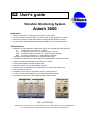
1
" User's guide
Vibration Monitoring System
Adash 3600
Application:
!
!
!
!
Vibration diagnostics, monitoring and protective on-line system
On-line vibration monitoring system of engines, fans, pumps, gearboxes, turbines …
Machines monitoring system with outputs to measuring and feedback systems
On-line system with possibility of temporary installation on problematic machines
Characteristics:
! Measuring of TRUE-RMS and TRUE-PEAK values, time signals and signal spectrum
LF
velocity mm/s in the band 10 - 1000 Hz
2
LIN
acceleration g (9.81 m/s ) in the band 0.8 Hz - 16 kHz
HFE
acceleration gHFE in the band 5 - 16 kHz (bearing condition)
ENV
envelope g in the band 5 - 16 kHz (bearing condition)
Possibility to start measurements by an external trigger signal
! Possibility of a vibration limit values setting to close indicating and protective relays
! Output of measured static data on current loops 4 - 20 mA
! Clearly visible display of measured static data
! Easy connection to control and feedback systems
! Indication of an overloading and a sensor defect or a measuring channel error
! Easy mounting on DIN rail
! Possibility to connect to an information network - TCP/IP protocol
! On-line or off-line data transferring to the Adash DDS 2000 software
! Possibility to extend the set with additional Adash 3600 modules
Ref: 11072002 KM
ADASH Ltd., Czech republic, tel.: +420 596 232 670, fax: +420 596 232 671, email: [email protected]
For next technical and contact information visit www.adash.net, www.adash.cz
ADASH Ltd.
Adash 3600-MAIN-COM-PWR
Contents
Before the First Start-up ..................................................................................................... 3
Terminal Board of the Adash 3600-MAIN Module ............................................................. 4
Description of Terminal Connectors .................................................................................. 4
Terminal Board of the Adash 3600-COM Module .............................................................. 6
Description of Terminal Connectors .................................................................................. 6
Terminal Board of the Adash 3600-PWR Module .............................................................. 7
Description of Terminal Connectors .................................................................................. 7
Description of Adash 3600-MAIN ....................................................................................... 8
Vibration Sensor ............................................................................................................... 8
Signal Paths ..................................................................................................................... 8
Binary (process) inputs ..................................................................................................... 8
Module Front Panel..........................................................................................................13
Interconnection of the Adash 3600 Set.............................................................................15
Recommended Procedure of Module Connection............................................................16
Connection of Other Devices ...........................................................................................19
System Extension ............................................................................................................20
Operation of the Adash 3600-MAIN Module......................................................................22
Errors Displayed by the Adash 3600-MAIN Module .........................................................22
Examples of Use.................................................................................................................23
Use of Binary Inputs.........................................................................................................23
Technical Specification of Adash 3600-MAIN...................................................................24
Technical Specification of Adash 3600-COM ...................................................................25
Technical Specification of Adash 3600-PWR ...................................................................26
Dimensioned Sketch of Adash 3600-MAIN, 3600-COM and 3600-PWR ..........................27
2
ADASH Ltd., Czech republic, tel.: +420 596 232 670, fax: +420 596 232 671, email: [email protected]
For next technical and contact information visit www.adash.net, www.adash.cz
ADASH Ltd.
Adash 3600-MAIN-COM-PWR
Before the First Start-up
Failure to respect any of the following recommendations may damage the device!
With a non-professional handling of voltage exceeding 24 V you expose yourself to
accident hazard.
1. Never connect any sensor to the ICP input of the unit other than the ICP sensor type!
If you are not sure, consult the procedure with your supplier.
2. Never connect the unit directly to the mains voltage!
3. Use only power supply units with a maximum nominal voltage of 5 V DC to supply the unit!
4. Use only power supply units with a maximum nominal voltage of 30 V DC to supply current
loops and binary inputs!
5. Pay attention to the correct polarity of the supplied voltage!
3
ADASH Ltd., Czech republic, tel.: +420 596 232 670, fax: +420 596 232 671, email: [email protected]
For next technical and contact information visit www.adash.net, www.adash.cz
ADASH Ltd.
Adash 3600-MAIN-COM-PWR
Terminal Board of the Adash 3600-MAIN
Module
Fig. Terminal board of the Adash 3600-MAIN module
The display of the terminal board corresponds to the front view of the module.
Description of Terminal Connectors
POWER
VCC
GND
supply voltage:
+5 V / 0.5 A,
0 V.
SIGNAL
SHLD
+ICP
-ICP
connection of vibration sensor (or OUT output of the Adash 3600-MPX module):
vibration sensor cable shield,
vibration sensor ICP input, positive pole, or +OUT output of Adash 3600-MPX,
vibration sensor ICP input, negative pole, or -OUT output of Adash 3600-MPX.
DC IN
+DC
-DC
DC input (temperature, pressure, ...):
DC input positive pole,
DC input negative pole.
AC OUT
AC OUT
AC GND
direct-current separated signal output from the connected vibration sensor:
AC signal,
0 V of the signal.
RS-485
485-A
485-B
485-AR
communication connection for the Adash 3600 system:
signal A of RS-485,
signal B of RS-485,
termination resistance 120R, for the termination of the interface to connect to terminal
connector 485-B.
4
ADASH Ltd., Czech republic, tel.: +420 596 232 670, fax: +420 596 232 671, email: [email protected]
For next technical and contact information visit www.adash.net, www.adash.cz
ADASH Ltd.
Adash 3600-MAIN-COM-PWR
PROCESS
+BIN1
+BIN2
-BIN12
+BIN3
+BIN4
-BIN34
binary inputs:
binary input No. 1, positive pole, supply max. DC 30 V / 4 mA,
binary input No. 2, positive pole, supply max. DC 30 V / 4 mA,
binary inputs No. 1 and 2, negative pole,
binary input No. 3, positive pole, supply max. DC 30 V / 4 mA,
binary input No. 4, positive pole, supply max. DC 30 V / 4 mA,
binary inputs No. 3 and 4, negative pole.
RELAY OK
NC
COM
CN
change-over contact of the OK relay:
signal under the limit of alarms,
common contact,
complementary NC
closed at rest.
RELAY ALERT change-over contact of the ALERT relay:
NC
signal exceeded the ALERT limit,
COM
common contact,
CN
complementary NC
closed at rest.
RELAY DANGER change-over contact of the DANGER relay:
NC
signal exceeded the DANGER limit,
COM
common contact,
CN
complementary NC
closed at rest.
RELAY SYSTEM change-over contact of the SYSTEM relay:
NC
system functions, vibration sensor connected,
COM
common contact,
CN
complementary NC
closed at rest.
LOOP1 ´LF´
+LOOP
- LOOP
4 – 20 mA output current loop of the measured value for the LF (ISO) signal:
loop positive pole, supply max. DC 30 V,
loop negative pole.
LOOP2
+LOOP
- LOOP
4 – 20 mA output current loop of the measured value for the bearing condition signal:
loop positive pole, supply max. DC 30 V,
loop negative pole.
Power supply unit
separate power supply unit 24 V / 80 mA (per order only):
+24V
power supply unit positive pole,
0V
0 V of the power supply unit.
5
ADASH Ltd., Czech republic, tel.: +420 596 232 670, fax: +420 596 232 671, email: [email protected]
For next technical and contact information visit www.adash.net, www.adash.cz
ADASH Ltd.
Adash 3600-MAIN-COM-PWR
Terminal Board of the Adash 3600-COM Module
Fig. Terminal board of the Adash 3600-COM module
The display of the terminal board corresponds to the front view of the module.
Description of Terminal Connectors
POWER
VCC
GND
supply voltage (terminal connectors with the same marking are interconnected inside):
+5 V / max. 50 mA,
0 V.
RS-485
communication connection for the Adash 3600 system (terminal connectors with the
same marking are interconnected inside):
signal A of RS-485,
signal B of RS-485,
termination resistance 120R, for the termination of the interface to connect to terminal
connector 485-B.
485-A
485-B
485-AR
ANALOG
-AC
+AC
GND
interconnection of the analogue output of the MAIN module with the BNC connector of
the COM module:
external contact of the BNC connector,
internal contact of the BNC connector,
0 V, non-used.
RS-232
232-GND
232-RXD
232-TXD
232-MOD
232-CTS
232-RTS
signals for continuous communication on RS-232:
common potential (ground),
data reception,
data transmission,
do not connect!,
ready for reception,
transmission released.
6
ADASH Ltd., Czech republic, tel.: +420 596 232 670, fax: +420 596 232 671, email: [email protected]
For next technical and contact information visit www.adash.net, www.adash.cz
ADASH Ltd.
Adash 3600-MAIN-COM-PWR
Terminal Board of the Adash 3600-PWR Module
Simple version
Double version
Fig. Terminal board of the Adash 3600-PWR module
The display of the terminal board corresponds to the front view of the module.
The voltage supply unit can have a combined version, with two separate supply units in one box: the
right side of the module then serves to supply the current loops and binary inputs of the Adash 3600
system, having an output voltage of 15 V DC.
Description of Terminal Connectors
INPUT
mains voltage supply 110-230 V.
OUTPUT
V+
V-
output of the DC stabilised voltage of 5 V / 2 A:
voltage supply unit positive pole,
voltage supply unit negative pole.
7
ADASH Ltd., Czech republic, tel.: +420 596 232 670, fax: +420 596 232 671, email: [email protected]
For next technical and contact information visit www.adash.net, www.adash.cz
ADASH Ltd.
Adash 3600-MAIN-COM-PWR
Description of Adash 3600-MAIN
Adash 3600-MAIN is the main module of the Adash 3600 system. This module performs its own
measurements and evaluation of vibration signals. It also controls other modules of the Adash 3600
system.
Vibration Sensor
The Adash 3600-MAIN module is equipped with one input for the connection of a vibration sensor
with ICP supply. The used sensor must be an accelerometer (acceleration sensor). Its nominal
sensitivity must be programmed during the unit configuration via the Adash 3600 Setup program.
The sensor is connected to the +ICP and -ICP terminal connectors of the Adash 3600-MAIN unit.
If the single channel basic Adash 3600 set is extended with one or more Adash 3600-MPX modules to
achieve a multi-channel set, then the nominal sensitivity must be programmed for each connected
vibration sensor.
The sensors are connected to the +ICP and -ICP inputs of the Adash 3600-MPX module.
Signal Paths
The analogue signal from the vibration sensor (accelerometer) is conditioned prior to its conversion to
the digital form:
- by filtration via an adequate frequency filter
- by integration or envelope modulator.
The method of the measured signal conditioning is determined by the selection of a suitable signal
path.
The Adash 3600-MAIN module has four signal paths for vibration measurement:
Signal
Result
Frequency
Signal
path
unit
band
conditioning
----------------------------------------------------------------------------------------------------LF
[mm/s]
10 – 1000 Hz
integration
HF
[g]
5 - 16 kHz
none
LIN
[g]
0.8 Hz – 16 kHz
none
ENV
[g]
5 - 16 kHz
envelope modulator
All parameters, incl. the signal path, are assigned to the measurement during the system configuration
via the Adash 3600 Setup program.
Binary (process) inputs
Some machine works permanently without often changes of working conditions, but works of some
machine is changed quite often. If machine works without changes, then the way of measuring of
vibration is without changes too. But if working condition of the machine is often changed, then way of
8
ADASH Ltd., Czech republic, tel.: +420 596 232 670, fax: +420 596 232 671, email: [email protected]
For next technical and contact information visit www.adash.net, www.adash.cz
ADASH Ltd.
Adash 3600-MAIN-COM-PWR
measuring of vibration must be changed too. The A3600 system measure the machine even is OFF.
To stop of the measuring on the turned-off machine is possible to use binary (process) inputs, which
stops measuring only on the turned-off machine. On the working machines will be still measuring
performed. Binary inputs are possible to use for dynamic data measuring (measuring of time or
spectra) too. The dynamic data measuring considerably size of database. You can also use binary
inputs for measuring of dynamic data.
Other case is a load change on a machine. The load change on the machine usually causes speed
change and power change. If speed and power of machine is changed, then we want change the way
of measuring of vibration too. For measuring change is possible to use binary inputs. The A3600
system contains 4 binary inputs, so we can set 4 different setups of measuring. If the machine works
with greater load, then vibrations are greater too, but in this case greater vibrations don't mean a
machine failure. If alarm limit doesn't change, then the system A3600 can detect false alarm. You can
also use binary inputs to change of alarm limits.
The binary inputs of the Adash 3600-MAIN unit serve to identify the measured machine state (run
up, coast down, ...). The module A3600MAIN set the pre-defined measuring base on the state of
binary inputs.
Binary inputs are common terminals which are situated on the module A3600MAIN and which can be
connecting to the power supply. If voltage from the process control system (PLC) is used as power
supply, then process control system gets information about measured machine state to the A3600
system. A user control power supply can be used too. The binary inputs must be supply by DC voltage
in the range of 4 – 30 V, current 4 mA.
If binary inputs are connected to the power supply and if are defined their functions, then A3600MAIN
module tests voltage on the binary inputs (binary inputs are active or passive) and depend on the state
of binary inputs set the pre-defined measuring.
Note. The A3600 system doesn't measure voltage on the binary input.
Binary inputs can be used for:
- setting of different alarm limits
- start of measuring
- start of dynamic data measuring
How simply start
Module A3600-MAIN makes possible to scan up to 4 binary inputs. State of binary inputs is indicated
by LED on the front panel of A3600MAIN module.
To set binary inputs use the A3600Setup application.
state of binary inputs on
the front panel of MAIN
module.
Attention!!! Terms "binary inputs" and " process inputs" are synonyms, which name the same
terminal of the A3600MAIN module.
9
ADASH Ltd., Czech republic, tel.: +420 596 232 670, fax: +420 596 232 671, email: [email protected]
For next technical and contact information visit www.adash.net, www.adash.cz
ADASH Ltd.
Adash 3600-MAIN-COM-PWR
Setting of alarm by binary inputs
Choose radio-button By bin inputs in the MPX - Channel window and define group of alarm limits for
used binary input. Alarm limits will depend on the active binary input. If more binary inputs are active,
then leftmost active binary input has priority.
setting of alarm limits
by binary inputs
Measure triggering by binary inputs
Measuring on the input channel of the A3600 can be triggered by binary inputs (BIN1 - BIN3). This
setting is available only in the Service mode (Mode - Change mode - password: 456654) of
A3600Setup. Click on the button Trigger and select binary input, which will be trigger a measuring.
The measuring will start only if selected binary input is active. Binary input must be active all the
measuring time. If this function is used, then blinks T control LED on the front panel of the A3600MAIN
module.
10
ADASH Ltd., Czech republic, tel.: +420 596 232 670, fax: +420 596 232 671, email: [email protected]
For next technical and contact information visit www.adash.net, www.adash.cz
ADASH Ltd.
Adash 3600-MAIN-COM-PWR
Triggering of a dynamic data measuring by binary inputs
If you use this function, then dynamic data measuring depends on the binary input. Choose triggering
binary input from the trig combo-box in the MPX - Channel Dynamic data configuration window. A
dynamic data measuring will start only if selected binary input is active. Binary input needn't be active
all the measuring time.
11
ADASH Ltd., Czech republic, tel.: +420 596 232 670, fax: +420 596 232 671, email: [email protected]
For next technical and contact information visit www.adash.net, www.adash.cz
ADASH Ltd.
Adash 3600-MAIN-COM-PWR
triggering of dynamic
data measuring
Hints for measurement triggering
1. If you want to trig all measuring types (static and dynamic) by one binary input, then static data
trigger must be BIN and dynamic data trigger must be Always.
2. If you want to trig dynamic data only, then static data trigger must be Free run and dynamic data
trigger must be BIN.
3. Reduction of speed of the measuring of the A3600 system can be caused by Data Distribution to
the NET module and by autorange. A3600 waits for communication with PC some measuring cycles
(5 in this case). If communication is done and dynamic data are saved to PC, then measuring
continues. If communication fails, then data are stored to the memory module and measuring
continues. If data distribution is not used, then you uncheck the checkbox - see picture below.
Measuring ranges for all channels are stored in the MAIN module memory. If level of vibrations is
relatively stable on all channels, then autorange is not needed to use. Using of the autorange is
recommended only for measuring on the special machines, which generate unstable value of
vibrations. Autorange is not needed for the measuring on the standard machine.
Note. If MAIN module is overloaded by sudden increasing of the vibrations, then autorange is used
automatically.
4. How long must be the binary input active? It depends on the measuring settings. There are some
examples of the time of measuring (all of the measurements are without autorange, averaging and
data distribution to the NET module):
- LF RMS: 2 sec
- LF RMS + LF TIME: 6sec
- LF RMS + HF RMS: 3sec
- LF RMS + LF TIME + HF RMS + HF TIME: 11sec
12
ADASH Ltd., Czech republic, tel.: +420 596 232 670, fax: +420 596 232 671, email: [email protected]
For next technical and contact information visit www.adash.net, www.adash.cz
ADASH Ltd.
Adash 3600-MAIN-COM-PWR
Data distribution to
the NET module
A3600 always
autoranges before
measuring
A3600 waits for
communication with PC
five measuring cycles
Module Front Panel
On the front 3600-MAIN module panel all information is displayed on the state of the Adash 3600
system.
Fig. Front panel of the Adash 3600-MAIN module
Display of the Measured Signals
ISO
vibration RMS value in 10 – 1000 Hz band at velocity [mm/s], signal path LF
RMS value of bearing condition vibration analysis at acceleration [g], assigned signal path HF,
LIN or ENV.
Indication of the Output Relays Condition
The overload of the set alarm limits is signalled by the indicators situated in the SIGNAL box.
13
ADASH Ltd., Czech republic, tel.: +420 596 232 670, fax: +420 596 232 671, email: [email protected]
For next technical and contact information visit www.adash.net, www.adash.cz
ADASH Ltd.
Adash 3600-MAIN-COM-PWR
Indicator
Signals
-----------------------------------------------------------------------------------------------O.K.
no set limit has been exceeded (the OK relay closed)
ALERT
the ALERT limit exceeded, the ALERT relay closed
DANGER
the DANGER limit exceeded, the DANGER relay closed
Indication of the BIN Input Signals Condition
The binary signals condition is indicated by the indicators in the PROCESS box.
Indicator
Signals
----------------------------------------------1
signal BIN1 active
2
signal BIN2 active
3
signal BIN3 active
4
signal BIN4 active
Unit State Indication
The unit state is indicated by the indicators in the STATUS box.
Indicator
Signals
-------------------------------------------------------------------------------------------------------------------------------------E - ERROR
unit error, the SYSTEM relay is open, detected error is displayed
M - MEASURE the signal is being measured
T - TRIGGER the unit is waiting for measurement trigger signal
C - COMM
communication of the unit with the connected system (data transmission between the
modules of the set)
S - SETUP
the unit measurement parameters are being set up
14
ADASH Ltd., Czech republic, tel.: +420 596 232 670, fax: +420 596 232 671, email: [email protected]
For next technical and contact information visit www.adash.net, www.adash.cz
ADASH Ltd.
Adash 3600-MAIN-COM-PWR
Interconnection of the Adash 3600 Set
In the basic version, the system is supplied as follows:
- Adash 3600-PWR .. power supply unit
- Adash 3600-MAIN .. main module
- Adash 3600-COM .. communication module (for system configuration via the Adash 3600 Setup
program).
Fig. Modules of the set basic version
These modules are connected to the set according to the following schematic:
Fig. Schematic of connection of the basic Adash 3600 set modules
15
ADASH Ltd., Czech republic, tel.: +420 596 232 670, fax: +420 596 232 671, email: [email protected]
For next technical and contact information visit www.adash.net, www.adash.cz
ADASH Ltd.
Adash 3600-MAIN-COM-PWR
Recommended Procedure of Module Connection
1. Disassembly of terminal connector covers.
Remove the terminal connector covers of the modules by means of a suitable tool.
Fig. Removal of terminal connector covers
2. Interconnection of supply terminal connectors (VCC and GND).
Fig. Interconnection of modules supply conductors
The supply conductors are identified by the following colours in the supplied set:
- red conductor, positive pole of the supply (+5 V, VCC)
- blue conductor, negative pole of the supply (GND).
Pay attention to the correct polarity of the supply voltage! The positive voltage is always at the
first terminal connector on the left.
16
ADASH Ltd., Czech republic, tel.: +420 596 232 670, fax: +420 596 232 671, email: [email protected]
For next technical and contact information visit www.adash.net, www.adash.cz
ADASH Ltd.
Adash 3600-MAIN-COM-PWR
3. Connection of communication terminal connectors (485-A, 485-B).
Fig. Interconnection of communication conductors
The communication conductors are identified by the following colours in the supplied set:
- white conductor, signal A of RS-485
- black conductor, signal B of RS-485.
4. Connection of interconnections (485-B, 485-AR).
At the last modules of the set, the terminal connectors of 485-B and 485-AR must be interconnected,
such interconnection terminating the interface RS-485 with resistors 120R. The termination resistors of
the interface are necessary to assure its higher resistance to interference.
Fig. Interconnection of terminal connectors with termination resistors on RS-485
17
ADASH Ltd., Czech republic, tel.: +420 596 232 670, fax: +420 596 232 671, email: [email protected]
For next technical and contact information visit www.adash.net, www.adash.cz
ADASH Ltd.
Adash 3600-MAIN-COM-PWR
5. Connection of the vibration sensor.
To connect the vibration sensor with ICP supply to the Adash 3600-MAIN unit, a special shielded
twisted cable is supplied, which is marked and connected as follows:
Conductor
Sensor
Module
colour
terminal connector
terminal connector
---------------------------------------------------------------------------------Shield (braiding)
SHLD
White
A
+ICP
White / blue (black)
B
- ICP
Fig. Connection of the vibration sensor
6. Connection of mains power supply.
The terminal connectors for mains voltage supply for the entire set are located at the 3600-PWR
module and are indicated L (phase conductor) and N (neutral working conductor).
Supply terminal connectors
Fig. Position of terminal connectors 230 V
7. Replace the terminal connector covers.
The interconnection of the basic Adash 3600 set modules is completed and the system is ready for
configuration and measurement.
18
ADASH Ltd., Czech republic, tel.: +420 596 232 670, fax: +420 596 232 671, email: [email protected]
For next technical and contact information visit www.adash.net, www.adash.cz
ADASH Ltd.
Adash 3600-MAIN-COM-PWR
Connection of Other Devices
Current Loops 4 – 20 mA
The Adash 3600-MAIN unit has two current loops 4 – 20 mA for transmission / display of the
measured data. Loop1 is assigned to measurement ISO [mm/s] on signal path LF; Loop2 is assigned
to the selected measurement [g] via one of the remaining signal paths HF, LIN, ENV.
The assignment of the signal path to Loop2 is carried out via the Adash 3600 Setup program.
The output current loops of the Adash 3600-MAIN module are passive, therefore they must be
supplied by an external DC voltage unit in the range of 8 – 30 V. The range of the displayed MIN and
MAX data, which correspond to the output current of loop 4 – 20 mA, can be programmed via Adash
3600 Setup.
I
I
[mA]
[mA]
20
20
4
4
0 = MIN
MAX DATA
0
MIN
MAX
DATA
a) Unsuppressed beginning of data, MIN = 0
b) Suppressed beginning of data, MIN > 0
Fig. Conversion characteristics of the current loop
Binary (Process) Inputs
The binary inputs of the Adash 3600-MAIN unit serve to define the measured machine state (run
up, coast down, ...). According to the state of these inputs, various levels of alert and critical limits can
be programmed for each measurement.
The binary inputs must be excited by DC voltage in the range of 4 – 30 V, current 4 mA.
Fig. Connection of current loops and binary (process) inputs of the Adash 3600-MAIN module
19
ADASH Ltd., Czech republic, tel.: +420 596 232 670, fax: +420 596 232 671, email: [email protected]
For next technical and contact information visit www.adash.net, www.adash.cz
ADASH Ltd.
Adash 3600-MAIN-COM-PWR
Measurement by an External Analyser
1. To connect an external analyser to the Adash 3600 set, the Adash 3600-COM module is equipped
with a BNC connector marked SIGNAL, to which the measured signal is fed from the vibration sensor.
This signal is fed to the connector from the AC OUT and AC GND terminal connectors of the Adash
3600-MAIN module and is already free of the DC component of ICP supply.
NOTE: If you are NOT using a multiplexer unit
Before connecting the analyser to the SIGNAL connector of the
Adash 3600-COM module, put a measurement terminal on its
second connector marked SERIAL, which will assure the
interruption of measurement at the Adash 3600-MAIN module
and the outlet of the measured signal with amplification 1
to connector SIGNAL.
Fig. Measurement terminal
2. If you connect the analyser directly to the +ICP and -ICP terminal connectors of the Adash 3600MAIN module, you measure the signal from the vibration sensor directly without any conditioning,
therefore including the DC component of ICP supply (approx. 12 V).
System Extension
The basic single channel Adash 3600 set can be extended to a multi-channel set by connecting the
Adash 3600-MPX modules. The multi-channel sets can be further completed with other modules,
which will assure the display, archiving and processing of the measured data.
Multi-channel Set
A multi-channel set can be created from the basic Adash 3600 set by extending it with 1 to 8 Adash
3600-MPX modules. Up to 8 vibration sensors can be connected to each multiplexer module, up to
four measurement types can be requested at each sensor via 4 signal paths LF, HF, LIN and ENV.
The configuration of the requested measurement types at individual vibration sensors is performed via
the Adash 3600 Setup program.
Network On-line Data Transmission
If the Adash 3600 set is mounted with the Adash 3600-NET network communication module (it
replaces the Adash 3600-COM module in the set), on-line transmission of the measured data to a host
PC via LAN network is enabled.
For archiving and processing of the measured data the DDS 2000 user software by Adash is required
on the host PC. If also there is on-line measured data to be processed, the user software must be
complemented with DDS Data Manager, which controls the data transfer from the A3600 to the PC.
20
ADASH Ltd., Czech republic, tel.: +420 596 232 670, fax: +420 596 232 671, email: [email protected]
For next technical and contact information visit www.adash.net, www.adash.cz
ADASH Ltd.
Adash 3600-MAIN-COM-PWR
Archiving of Measured Data
The Adash 3600 set can be extended with the Adash 3600-MEM memory module, which archives
measured data on the flash card with a capacity of 16 MB to 128 MB. The flash card with the
measured data can be removed from the module at any time and the archived data can be imported to
the DDS 2000 user software by Adash for further processing.
For the systems with on-line network transmission of the measured data, all the on-line data are
stored on the flash card that were not transmitted via network to the host PC and were overwritten with
new data in the memory of the Adash 3600-NET module. In the set without the Adash 3600-MEM
memory module the old on-line data would be lost. If the host PC is not continuously in operation but
the user wants to archive all the on-line data, the Adash 3600 set must use the memory module.
Alarm Limits Signalling
The multi-channel Adash 3600 set can be extended with 1 to 8 Adash 3600-REL relay outputs
modules for the signalling of alarm limits overload of individual vibration sensors. Each Adash 3600REL module is mounted with up to eight relay pairs. Each pair can be appropriately programmed so
that it signals, by the close/open combination, three states: OK, ALERT and DANGER.
The assignment of a relay group to a sensor and the programming of the group behaviour for each of
the three signalled states is carried out via the Adash 3600 Setup program.
Current Loops 4 - 20 mA
The basic Adash 3600 set has two current loops 4 – 20 mA for measured data output. By mounting 1
to 8 Adash 3600-LOOPS modules, their number can be significantly increased. Each Adash 3600LOOPS module has 8 or 16 programmable current loops 4 – 20 mA for measured data output. In
addition, each current loop of the Adash 3600-LOOPS module is able to display error conditions of
measurement by output currents 3.5 mA, 3.75 mA, 22 mA and 24 mA.
The assignment of the current loop to the measurement, the setting of the measured data range for
display by output current 4 – 20 mA and the assignment of output currents to error conditions is
performed via the Adash 3600 Setup program.
21
ADASH Ltd., Czech republic, tel.: +420 596 232 670, fax: +420 596 232 671, email: [email protected]
For next technical and contact information visit www.adash.net, www.adash.cz
ADASH Ltd.
Adash 3600-MAIN-COM-PWR
Operation of the Adash 3600-MAIN Module
If the unit is in operation, it displays continuously measurement results and, based on the results,
updates the output current of current loops 4 – 20 mA in accordance with their set measurement
range. At the same time, status indicators M (measurement), S (measurement parameters setting) and
C (communication between the modules of the set) flash.
Also the measured signal values are checked continuously for the set alarm limits overload and, based
on the evaluation, the relative relays switch. If no alarm limit is exceeded, the OK relay is active. If any
alarm limit is exceeded, the OK relay opens and the relay that signals the state of the relative
exceeded limit becomes active.
If no error is detected, the SYSTEM relay closes. If communication failure, sensor supply failure etc.
occur, indicator E switches on and the type of error appears on the display. Simultaneously, the
SYSTEM relay opens.
Errors Displayed by the Adash 3600-MAIN Module
ERR ICP
- sensor supply error, sensor disconnected or short-circuited, measurement
impossible.
ERR OVR
- sensor overexcited, vibration value exceeded the measurement range,
measurement impossible.
ERR NET
- data buffer memory for network communication is full, current values cannot be
stored.
ERR MEM
ERR STO
- no response from the Adash 3600-MEM module, usually the flash card is removed.
- data storage error, usually the STOP delay of the Adash 3600-MEM module is
counting down.
ERR xx
- error of communication with module No. xx (each module has its No. xx on the
system interface)
List of Module Numbers on Interface RS-485
In case of error, the module number appears on the Adash 3600-MAIN display in the HEX form.
Module number
Module type
-------------------------------------------------------------------------------------11H to 1BH
Adash 3600-REL, module 1 to 12 respectively
21H to 2BH
Adash 3600-MPX, module 1 to 12 respectively
31H to 3FH
Adash 3600-LOOPS, module 1 to 15 respectively
51H
Adash 3600-COM, COMD or NET
53H
Adash 3600-GSM
55H
Adash 3600-MAIN
57H
Adash 3600-MEM
22
ADASH Ltd., Czech republic, tel.: +420 596 232 670, fax: +420 596 232 671, email: [email protected]
For next technical and contact information visit www.adash.net, www.adash.cz
ADASH Ltd.
Adash 3600-MAIN-COM-PWR
Examples of Use
Use of Binary Inputs
According to the state of four binary inputs of the Adash 3600-MAIN unit, up to 5 alarms can be set up,
for instance by assigning as follows:
Binary inputs status
Alarm
Limit
Measured machine status
--------------------------------------------------------------------------------------------------------------active BIN1
ALARM 1:
15 mm/s
run-up
active BIN2
ALARM 2:
10 mm/s
operating condition
active BIN3
ALARM 3:
15 mm/s
coast down
active BIN4
ALARM 4:
12 mm/s
increased power
No input active
ALARM 0:
0 mm/s
machine does not run
Note.
The 0 mm/s value corresponds to the state “ALARM OFF”.
If two binary inputs are activated simultaneously, the input with higher ordinal number has higher
priority (the BIN2 input precedes the BIN1 input etc.).
23
ADASH Ltd., Czech republic, tel.: +420 596 232 670, fax: +420 596 232 671, email: [email protected]
For next technical and contact information visit www.adash.net, www.adash.cz
ADASH Ltd.
Adash 3600-MAIN-COM-PWR
Technical Specification of Adash 3600-MAIN
Inputs:
- 1 for vibration measurement (accelerometer with ICP supply)
- 4 binary for definition of machine state (run, coast down, run up, ...) and for
external trigger
- 1 DC for DC value of operational quantity (power, machine speed,
temperature,...)
Outputs:
- 1 analogue AC buffered signal from the vibration sensor (output shortcircuiting will not effect the signal measured by the unit)
- 4 relays with change-over contacts (~250 V / 0.4 A, 100 W):
- OK unit
- OK state (no critical value exceeded)
- Alert limit exceeded
- Danger limit exceeded
- 2 current loops 4 – 20 mA, galvanically separated:
- vibration power by ISO 2372 via signal path LF
- bearings condition measured via the selected signal path HF, LIN,
ENV
Data processing:
- vibration power measurement by ISO 2372 - LF (mm/s in 10 – 1000 Hz
band)
- bearings condition measurement
- HF (g in 5 – 16 kHz band)
- LIN (g in 0.8 Hz – 16 kHz band)
- ENV (g envelope analysis - HFE in 5 – 16 kHz band)
- time signal and signal spectrum via LF, HF, LIN and ENV signal paths
Signal conditioning:
- integration
- envelope modulation in 5 – 16 kHz band
Sampling frequency: - 4 kHz for vibration power measurement by ISO 2372
- 40 kHz for bearing condition measurement
Limits:
- Alert and Danger
(The limits are set up for each measured quantity separately: various limit
values can be set up for various machine operating states defined by binary
channels. Various limit levels can be set up according to the operational
quantity value defined by the level of DC input.)
Trigger:
- auto (free run)
- external trigger
Measurement interval: - approx. 750 ms (for measurements of static values only)
Interface:
- serial RS-485 for communication between the modules of the set
- serial RS-232 via the Adash 3600-COM module
Protection:
- IP20
Temperature range:
- -10 °C to +50 °C
Supply:
- 5 V / 0.5 A DC
Dimensions:
- 106 x 90 x 58 mm
Weight:
- 275 g
Mounting:
- DIN rail
Unit setting:
- using the Adash 3600 Setup program from PC via serial interface RS-232
24
ADASH Ltd., Czech republic, tel.: +420 596 232 670, fax: +420 596 232 671, email: [email protected]
For next technical and contact information visit www.adash.net, www.adash.cz
ADASH Ltd.
Adash 3600-MAIN-COM-PWR
Technical Specification of Adash 3600-COM
Inputs:
- 1 analogue, vibration sensor AC signal from the 3600-MAIN unit
Outputs:
- 1 analogue buffered signal from vibration sensor (output short-circuiting will
not effect the signal measured by the unit) at the BNC SIGNAL connector
Interface:
- serial RS-485 for communication between the modules of the set
- serial RS-232 for communication with the superior PC via the SERIAL
connector
Transmission parameters:
- 8 bits of data
- without parity
- 1 stop bit
- version COM (basic)
version COMD (on-line RS-232)
version NET (on-line RS-232 / LAN)
2400 Bd or 4800 Bd
4800 Bd or 9600 Bd
from 600 Bd to 57600 Bd
Protection:
- IP20
Temperature range:
- -10 °C to +50 °C
Supply:
- 5 V / 50 mA DC
Dimensions:
- 53 x 90 x 58 mm
Weight:
- 140 g
Mounting:
- DIN rail
Unit setting:
- using the Adash 3600 Setup program from PC via serial interface RS-232
25
ADASH Ltd., Czech republic, tel.: +420 596 232 670, fax: +420 596 232 671, email: [email protected]
For next technical and contact information visit www.adash.net, www.adash.cz
ADASH Ltd.
Adash 3600-MAIN-COM-PWR
Technical Specification of Adash 3600-PWR
Input voltage:
- 110~230 V 50-60Hz
Output voltage:
- 5 V / 2 A for simple version
- 5 V / 2 A + 15 V / 0,9 A for double version
Protection:
- IP20
Temperature range:
- -10 °C to +50 °C
Supply:
- ~230 V
Dimensions:
- 53 x 90 x 58 mm for simple version
- 106 x 90 x 58 mm for double version
Weight:
- 130 g for simple version
- 255 g for double version
Mounting:
- DIN rail
26
ADASH Ltd., Czech republic, tel.: +420 596 232 670, fax: +420 596 232 671, email: [email protected]
For next technical and contact information visit www.adash.net, www.adash.cz
ADASH Ltd.
Adash 3600-MAIN-COM-PWR
Dimensioned Sketch of Adash 3600-MAIN,
3600-COM and 3600-PWR
Adash
3600
SERIAL
90 mm
SIGNAL
COMM
53 mm
106 mm
62 mm
3600
90 mm
Adash
POWER
53 mm
33 mm
48 mm
58 mm
27
ADASH Ltd., Czech republic, tel.: +420 596 232 670, fax: +420 596 232 671, email: [email protected]
For next technical and contact information visit www.adash.net, www.adash.cz