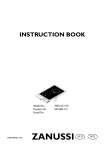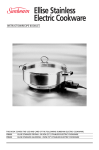
1
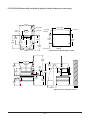
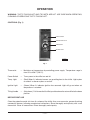
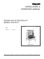
INSTALLATION &
OPERATION MANUAL
ROUND GAS TILTING SKILLET
MODEL VGCTS16
MODEL
VGCTS16
ML-114827
MODEL VGCTS16
VULCAN-HART
FORM 31041 (12-97)
COMPANY,
P.O.
BOX
696,
LOUISVILLE,
KY
40201-0696,
TEL. (502) 7 7 8 - 2 7 9 1
IMPORTANT FOR YOUR SAFETY
THIS MANUAL HAS BEEN PREPARED FOR PERSONNEL QUALIFIED TO INSTALL GAS
EQUIPMENT, WHO SHOULD PERFORM THE INITIAL FIELD START-UP AND
ADJUSTMENTS OF THE EQUIPMENT COVERED BY THIS MANUAL.
POST IN A PROMINENT LOCATION THE INSTRUCTIONS TO BE FOLLOWED IN THE
EVENT THE SMELL OF GAS IS DETECTED. THIS INFORMATION CAN BE OBTAINED
FROM THE LOCAL GAS SUPPLIER.
IMPORTANT
IN THE EVENT A GAS ODOR IS DETECTED, SHUT
DOWN UNITS AT MAIN SHUTOFF VALVE AND
CONTACT THE LOCAL GAS COMPANY OR GAS
SUPPLIER FOR SERVICE.
FOR YOUR SAFETY
DO NOT STORE OR USE GASOLINE OR OTHER
FLAMMABLE VAPORS OR LIQUIDS IN THE
VICINITY OF THIS OR ANY OTHER APPLIANCE.
WARNING
IMPROPER INSTALLATION, ADJUSTMENT,
ALTERATION, SERVICE OR MAINTENANCE CAN
CAUSE PROPERTY DAMAGE, INJURY OR DEATH.
READ THE INSTALLATION, OPERATING AND
MAINTENANCE INSTRUCTIONS THOROUGHLY
BEFORE INSTALLING OR SERVICING THIS
EQUIPMENT.
IN THE EVENT OF A POWER FAILURE, DO NOT
ATTEMPT TO OPERATE THIS DEVICE.
© VULCAN-HART COMPANY, 1997
—2—
TABLE OF CONTENTS
GENERAL. . . . . . . . . . . . . . . . . . . . . . . . . . . . . . . . . . . . . . . . . . . . . . . . . . . . . . . . . . . . . . . . . . . . . . . 4
INSTALLATION . . . . . . . . . . . . . . . . . . . . . . . . . . . . . . . . . . . . . . . . . . . . . . . . . . . . . . . . . . . . . . . . . . 4
Unpacking . . . . . . . . . . . . . . . . . . . . . . . . . . . . . . . . . . . . . . . . . . . . . . . . . . . . . . . . . . . . . . . . . 4
Location . . . . . . . . . . . . . . . . . . . . . . . . . . . . . . . . . . . . . . . . . . . . . . . . . . . . . . . . . . . . . . . . . . 4
Installation Codes and Standards . . . . . . . . . . . . . . . . . . . . . . . . . . . . . . . . . . . . . . . . . . . . . . 5
Installation Without Skillet Optional 201⁄2" High Stand . . . . . . . . . . . . . . . . . . . . . . . . . . . . . . 5
Leveling . . . . . . . . . . . . . . . . . . . . . . . . . . . . . . . . . . . . . . . . . . . . . . . . . . . . . . . . . . . . . . . . . . 6
Gas Connections . . . . . . . . . . . . . . . . . . . . . . . . . . . . . . . . . . . . . . . . . . . . . . . . . . . . . . . . . . . 6
Testing the Gas Supply System . . . . . . . . . . . . . . . . . . . . . . . . . . . . . . . . . . . . . . . . . . . . . . . 6
Flue . . . . . . . . . . . . . . . . . . . . . . . . . . . . . . . . . . . . . . . . . . . . . . . . . . . . . . . . . . . . . . . . . . . . . . 6
Electrical Connections . . . . . . . . . . . . . . . . . . . . . . . . . . . . . . . . . . . . . . . . . . . . . . . . . . . . . . . 7
Floor Plan . . . . . . . . . . . . . . . . . . . . . . . . . . . . . . . . . . . . . . . . . . . . . . . . . . . . . . . . . . . . . . . . . 8
OPERATION . . . . . . . . . . . . . . . . . . . . . . . . . . . . . . . . . . . . . . . . . . . . . . . . . . . . . . . . . . . . . . . . . . . . 9
Controls . . . . . . . . . . . . . . . . . . . . . . . . . . . . . . . . . . . . . . . . . . . . . . . . . . . . . . . . . . . . . . . . . . 9
Before First Use . . . . . . . . . . . . . . . . . . . . . . . . . . . . . . . . . . . . . . . . . . . . . . . . . . . . . . . . . . . . 9
Lighting the Tilting Skillet . . . . . . . . . . . . . . . . . . . . . . . . . . . . . . . . . . . . . . . . . . . . . . . . . . . . 10
Using the Tilting Skillet . . . . . . . . . . . . . . . . . . . . . . . . . . . . . . . . . . . . . . . . . . . . . . . . . . . . . 10
Cleaning . . . . . . . . . . . . . . . . . . . . . . . . . . . . . . . . . . . . . . . . . . . . . . . . . . . . . . . . . . . . . . . . . 11
MAINTENANCE . . . . . . . . . . . . . . . . . . . . . . . . . . . . . . . . . . . . . . . . . . . . . . . . . . . . . . . . . . . . . . . . . 12
Lubrication . . . . . . . . . . . . . . . . . . . . . . . . . . . . . . . . . . . . . . . . . . . . . . . . . . . . . . . . . . . . . . . 12
Vent . . . . . . . . . . . . . . . . . . . . . . . . . . . . . . . . . . . . . . . . . . . . . . . . . . . . . . . . . . . . . . . . . . . . . 12
Service and Parts Information . . . . . . . . . . . . . . . . . . . . . . . . . . . . . . . . . . . . . . . . . . . . . . . . 12
TROUBLESHOOTING . . . . . . . . . . . . . . . . . . . . . . . . . . . . . . . . . . . . . . . . . . . . . . . . . . . . . . . . . . . . 12
—3—
Installation, Operation and Care of
ROUND GAS TILTING SKILLET
MODEL VGCTS16
PLEASE KEEP THIS MANUAL FOR FUTURE USE
GENERAL
Your Vulcan Round Tilting Skillet is a versatile piece of equipment. It allows you to stew, simmer, pan
fry, braise, grill, or saute, and all with a very uniform heat pattern. Capacity of Model VGCTS16 is 16
gallons (4.2 liters).
Optional accessories include a skillet support stand with drain pan.
Vulcan tilting skillets are produced with quality workmanship and material. Proper installation, usage
and maintenance of your tilting skillet will result in many years of satisfactory performance.
It is suggested that you thoroughly read this entire manual and carefully follow all of the instructions
provided.
INSTALLATION
Before installing, verify that the gas and electrical service agree with the specifications on the rating
plate located on the right side panel as you face the machine. If the supply and equipment requirements
do not agree, do not proceed with the installation. Contact your dealer or Vulcan-Hart Company
immediately.
UNPACKING
This tilting skillet was inspected before leaving the factory The transportation company assumes full
responsibility for safe delivery upon acceptance of the shipment. Immediately after unpacking, check
for possible shipping damage. If the tilting skillet is found to be damaged, save the packaging material
and contact the carrier within 15 days of delivery.
Carefully unpack tilting skillet and place in a work-accessible area as near to its final installed position
as possible.
LOCATION
The equipment area must be kept free and clear of combustible substances.
The skillet is intended for use on non-combustible floors. When installed, minimum clearance from
combustible and non-combustible construction must be 3" (7.6 cm) at the sides and 6" (15.2 cm) at the
rear.
—4—
The installation location must allow adequate clearances for servicing and proper operation.
The skillet must be installed so that the flow of combustion and ventilation air will not be obstructed.
Adequate clearance for air openings into the combustion chamber must be provided. Make sure there
is an adequate supply of air in the room to allow for that required for combustion of gas at the burners.
Do not permit fans to blow directly at the skillet. Wherever possible, avoid open windows next to the
skillet. Avoid wall-type fans which create air cross currents within the room.
INSTALLATION CODES AND STANDARDS
The Vulcan tilting skillet must be installed in accordance with:
In the United States of America:
1. State and local codes.
2. National Fuel Gas Code, ANSI-Z223.1 (latest edition). Copies may be obtained from The American
Gas Association, Inc., 1515 Wilson Blvd., Arlington, VA 22209.
3. National Electrical Code, ANSI/NFPA-70 (latest edition). Copies may be obtained from The
National Fire Protection Association, Batterymarch Park, Quincy, MA 02269.
In Canada:
1. Local codes.
2. CAN/CGA-B149.1 "Natural Gas Installation Code" (latest edition).
3. CAN/CGA-B149.2 "Propane Installation Code" (latest edition), available from the Canadian Gas
Association, 178 Rexdale Rd., Etobicoke, Ontario, Canada M9W1R3.
4. CSA Standard C22.2 No. 3 (latest edition) "Electrical Features of Fuel Burning Equipment." Copies
may be obtained from The Canadian Standard Association, 178 Rexdale Rd., Etobicoke, Ontario,
Canada M9W1R3.
INSTALLATION WITHOUT SKILLET OPTIONAL 201⁄2" HIGH STAND
1. Install skillet on 201⁄2" (521 mm) high working surface.
2. Correct location of skillet for tilting purposes is approximately 30" (761 mm) from the wall to the front
of the skillet base. Be sure the skillet tilts easily.
3. With bolts provided, secure skillet to properly leveled working surface.
4. Seal skillet to table top with Silastic or other sealing compound.
—5—
LEVELING
Place a carpenter's level on top of the skillet. Level the skillet front to back and side to side by turning
the adjustable feet.
GAS CONNECTIONS
Gas supply connections and any pipe joint compound used must be resistant to the action of propane
gases.
Location of the gas inlet is at the rear of the skillet. Codes require that a gas shutoff valve must be
installed in the gas line ahead of the skillet.
Connect gas supply. Make sure the pipes are clean and free of obstructions.
The skillet is equipped with fixed burner orifices which coincide with installation elevation.
Natural gas pressure regulators are preset for 7" (1.47 kPa) W.C. (Water Column); propane gas
pressure regulators are preset for 11" (2.74 kPa) W.C.
WARNING: PRIOR TO LIGHTING, CHECK ALL JOINTS IN THE GAS SUPPLY LINE FOR LEAKS.
USE SOAP AND WATER SOLUTION. DO NOT USE AN OPEN FLAME.
After piping has been checked for leaks, all piping receiving gas should be fully purged to remove air.
TESTING THE GAS SUPPLY SYSTEM
When gas supply pressure exceeds 1⁄2 psig (3.45 kPa), the skillet and its individual shutoff valve must
be disconnected from the gas supply piping system.
When gas supply pressure is 1⁄2 psig (3.45 kPa) or less, the skillet should be isolated from the gas supply
system by closing its individual manual shutoff valve.
FLUE
Do not obstruct the flow of flue gases from the flue located on the rear of the skillet. It is recommended
that the flue gases be ventilated to the outside of the building through a ventilation system installed by
qualified personnel.
From the termination of the flue to the filters of the hood venting system, a minimum clearance of 18"
(46 cm) must be maintained.
Information on the construction and installation of ventilating hoods may be obtained from the standard
for "Vapor Removal from Cooking Equipment," NFPA No. 96 (latest edition), available from the
National Fire Protection Association, Batterymarch Park, Quincy, MA 02269.
—6—
ELECTRICAL CONNECTIONS
WARNING: ELECTRICAL AND GROUNDING CONNECTIONS MUST COMPLY WITH THE
APPLICABLE PORTIONS OF THE NATIONAL ELECTRICAL CODE AND/OR OTHER LOCAL
ELECTRICAL CODES.
WARNING: THE SUPPLY CORD ON THE GAS TILTING SKILLET IS PROVIDED WITH A THREEPRONG GROUNDING PLUG. IT IS IMPERATIVE THAT THIS PLUG BE CONNECTED INTO A
PROPERLY GROUNDED THREE-PRONG RECEPTACLE. IF THE RECEPTACLE IS NOT THE
PROPER GROUNDING TYPE, CONTACT AN ELECTRICIAN. DO NOT REMOVE THE GROUNDING
PRONG FROM THIS PLUG.
A 120/60/1 supply cord is supplied at the rear of the skillet.
Do not connect the skillet to electrical supply until after gas connections have been made.
An electrical diagram is located inside the skillet control box.
—7—
FLOOR PLAN (Shown with and without optional stand and drain pan accessory)
29-1/4
(743)
29-1/4 (743)
4-1/4 (108)
5-5/8
(143)
15/16 (24)
DRAIN
17-5/8
(448)
2-3/4 (70)
27-7/16 (697)
15/16 (24)
1-3/4 (44)
14
(356)
13-5/16
(194)
17-3/16
(437)
26
(660)
29-7/8
(759)
7/16 (11) O
4 HOLES
2-1/8 (54)
MOUNTING WITHOUT OPTIONAL STAND
37-3/4
(959)
26 (660) ID
24-7/8
632
15
(381)
DRAIN
9-5/8
(244)
8-7/5
(222)
10
(254)
43-1/4
(1099)
3-3/4
(95)
18-1/2
(470)
POUR PATH
18
(457)
PL-52890
MOUNTING WITH OPTIONAL STAND
—8—
OPERATION
WARNING: THE TILTING SKILLET AND ITS PARTS ARE HOT. USE CARE WHEN OPERATING,
CLEANING OR SERVICING THE TILTING SKILLET.
CONTROLS (Fig. 1)
POWER SWITCH
TEMPERATURE LIGHT
THERMOSTAT
IGNITION LIGHT
PL-41053-1
Fig. 1
Thermostat
—
Maintains set temperature by controlling power supply. Temperature range is
from Off to 450°F (232°C).
Power Switch
—
Turns power to the skillet on and off.
Temp. Light
—
(Red) When lit, indicates burners are providing heat to the skillet. Light cycles
on and off as burner cycles on and off.
Ignition Light
—
(Green) When lit, indicates ignition has occurred. Light will go out when set
temperature is reached.
Tilting Handle
—
(Not shown.) Pull forward to tilt skillet; push backward to return skillet to the down
position.
BEFORE FIRST USE
Clean the protective metal oils from all surfaces of the skillet. Use a non-corrosive, grease dissolving
commercial cleaner, following manufacturer's directions. Rinse thoroughly and wipe dry with a soft
clean cloth. Clean all accessories. Rinse thoroughly and wipe dry.
—9—
LIGHTING THE TILTING SKILLET
1. Open main gas valve.
2. Ensure skillet is in the DOWN position.
3. Turn Power Switch ON. Set thermostat dial to desired setting. This will turn on the electronic
ignition. The gas solenoid valve will open, supplying gas to the burner. The RED temperature light
and the GREEN ignition light will come on.
4. If ignition is not achieved, turn the thermostat to OFF and turn the Power Switch to OFF. Wait 5
minutes before repeating steps 2 and 3.
5. When the skillet reaches set temperature, the RED temperature light and the GREEN ignition light
will go off and the burner will shut off. The burner will cycle on and off to maintain set temperature.
Shutdown
Turn thermostat to OFF. Turn Power Switch to OFF. For extended shutdown, turn thermostat, Power
Switch, and main gas valve OFF.
USING THE TILTING SKILLET
When the skillet is tilted, power supply to the burner is interrupted. The skillet can only be operated
in the down position.
To prevent discoloration of stainless steel cooking surface, do not turn the heat on unless the skillet
is covered with a fluid, a thin layer of cooking oil, or food to be cooked.
1. Grasp the tilting handle and tilt the skillet down as far as it will go and then back to ensure that it
moves easily.
2. Turn the Power Switch ON.
3. Set the Thermostat dial to HIGH (450°F / 232°C).
4. Preheat skillet and allow it to cycle in order to equalize heat across the entire pan surface.
5. Set the Thermostat dial to the desired cooking temperature.
Approx. Temp.
(°F)
(°C)
200
225-275
300-350
325-375
350-425
93
107-135
149-177
163-190
177-218
Function
Simmering
Sauteeing
Searing
Pan Frying
Grilling
— 10 —
6. At the end of cooking, turn the Thermostat to OFF and turn the Power Switch to OFF.
7. Skillet Without Optional Stand: Tilt the skillet to empty product into a food receiving pan.
Skillet With Optional Stand: The skillet is provided with a stationary support for holding the drain
pan. When unloading prepared foods, pull the drain pan out about 17" (432 mm) and place a food
receiving pan in it. Tilt the skillet to remove product. The drain pan is removable for cleaning.
CLEANING
WARNING: UNPLUG ELECTRICAL POWER SUPPLY BEFORE CLEANING.
Do not use corrosive cleaning agents
After Each Use
The tilting skillet should be cleaned after each use. Clean with warm water and a mild detergent. Rinse
thoroughly and wipe dry with a soft clean cloth.
If your skillet is equipped with the optional stand and drain pan accessory, remove the drain pan and
clean it in a sink as you would any utensil.
Once A Day
Thoroughly clean the skillet with warm water and a mild detergent. Rinse thoroughly and wipe dry with
a soft clean cloth.
Stainless Steel
Clean stainless steel surfaces with a damp cloth and polish with a soft dry cloth. To remove
discolorations, use a non-abrasive cleaner.
— 11 —
MAINTENANCE
WARNING: THE TILTING SKILLET AND ITS PARTS ARE HOT. USE CARE WHEN OPERATING,
CLEANING OR SERVICING THE TILTING SKILLET.
WARNING: UNPLUG ELECTRICAL POWER SUPPLY.
LUBRICATION
Never grease or oil the pivot bearings as this may cause problems with tilting. Bearings are oilite and
never require lubrication.
VENT
Periodically check the flue, when the skillet is cool, to be sure it is free of obstructions.
SERVICE AND PARTS INFORMATION
To obtain service and parts information concerning this tilting skillet, contact the Vulcan-Hart Service
Agency in your area (refer to listing supplied with the skillet), or Vulcan-Hart Company Service
Department at the address or phone number shown on the front cover of this manual.
TROUBLESHOOTING
PROBLEM
POSSIBLE CAUSES
Burner does not come on.
1.
2.
3.
4.
Skillet difficult to tilt.
Dirt in oilite bearings causing it to bind. Call your
local Vulcan-authorized servicer.
FORM 31041 (12-97)
— 12 —
Gas supply to skillet is not on.
Manual shut-off valve is off.
Thermostat is not turned on.
Pan is not in lowest position.
PRINTED IN U.S.A.