1
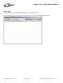
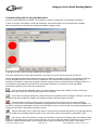
Integrity Voice Alarm Routing Matrix
SigNET Integrity
Editor User Guide
Software Revision 5.0.9.1
© 1999-2005 SigNET (AC) Ltd.
© 1999-2005 SigNET (AC) Ltd.
Page 1 of 36
DocNo.DCM0003212 ADS 14/11/05 rev 2
Integrity Voice Alarm Routing Matrix
Contents
Overview
Context Sensitive Help
Summary of Page Tabs
Cause and Effects Page
Hardware Page
Options Page
Simulation Page
Specification Page
Integrity Config Page
Notes Page
Cause and Effects Page
Input Matrix
Cause and Effects Matrix
Hardware Page
CPU Card
Slot Properties
Service
Mute
1LS Card
1LS Slot Properties
1LS Group Button/Monitoring
1LS Contact Inputs
PA16 Card
PA16 Slot Properties
PA16 Slot Group Buttons/Monitoring
PA16 Paging Panel
SVM Card
SVM SoundVault Module Properties
SVM Message 1
BGM Card
BGM Properties
BGM Internal Contacts
BGM External Contacts
CI16 Card – Normal Mode
CI16 Hardware – Expert mode
OP2 Card
OP2 Zone 1
GPI Card
MPP32i
MPP56i
MPP24Wi
MPCi Range
Controlling More Than One Mainframe from MPC Console(s
Button Types
Function Buttons
Modal(Mode) Buttons
Group Buttons
How an MPC Handles Multiple Integrity Units
Using Multiple MPC Consoles
Icon Picker
Politeness
Options Page
Simulation Page
Specification Page
Notes Page
Communicating with the Integrity Mainframe
© 1999-2005 SigNET (AC) Ltd.
Page 2 of 36
3
4
4
4
4
4
4
4
4
4
5
5
6
7
8
8
9
9
10
10
10
11
12
12
12
13
14
14
15
16
16
16
17
18
19
20
20
21
21
22
22
23
26
26
27
27
28
28
29
29
30
31
32
33
34
35
DocNo.DCM0003212 ADS 14/11/05 rev 2
Integrity Voice Alarm Routing Matrix
Overview
Integrity is a revolutionary new way of specifying and designing a complete Voice Alarm / Public Address routing
matrix (mainframe). It demystifies the 'black art' of system specification and configuration via easy to understand
software and hardware.
Integrity Editor is a visual configuration tool that provides an easy to understand view of the VA/PA system inputs,
outputs and priorities. You can simulate change audio input priorities, alter cause and effects and audition fire alarm
messages, as well as have the option to add other messages such as alert, evacuate, bomb etc. or your own
customised messages. Once satisfied with the system design the file is saved for uploading into the hardware.
The mainframe comprises a 19" 2U rack mounting case complete with controls, status display, Central Processor Unit
(CPU) card and eight audio channel backplane. Up to eight audio input cards and eight two-zone audio output cards
can be installed for connection to input sources, amplifiers etc. The system has built in fault monitoring and is fully
compliant to all relevant VA/PA standards.
Audio input and output cards are configured separately and all cards are controlled by the CPU card, although the unit
also has a hardware fail mode which allows the mainframe to be operated as an all-call system if one or more
processors fail.
Integrity is ideal for Voice Alarm / Public Address systems requiring 2 -16 zones fed from up to 8 (more in some
cases) audio input sources. Up to four Integrity mainframes can be interconnected to allow the construction of
systems with up to 64 audio zones.
Please contact SigNET (AC) Ltd. if you require information on larger systems or for single zone systems.
SigNET (AC) Ltd.
Tower Road,
Glover Industrial Estate,
Washington
Tyne & Wear
NE37 2SH
Telephone: (+44 ) 191 4174551
Fax:
(+44 ) 191 4170634
Internet :
E-Mail :
www.signet-ac.co.uk
[email protected]
© 1999-2005 SigNET (AC) Ltd.
Page 3 of 36
DocNo.DCM0003212 ADS 14/11/05 rev 2
Integrity Voice Alarm Routing Matrix
Context Sensitive Help
You can obtain help on a page (Cause and Effects, Hardware, etc.) by clicking that tab and pressing F1. More specific
help can be obtained by clicking in the appropriate area of the picture shown in the help file.
Summary of Page Tabs
Cause and Effects Page
This page allows the system designer to determine how control triggers operate and which audio input sources are
connected to output zones at what priority and to test the results.
Hardware Page
This page allows you to manage the selection of input and output cards. Each card is configured separately.
Options Page
This page allows you to customise the SigNET Integrity configuration software to suit non-standard applications.
Simulation Page
This page allows you to set the default paths to the audio files used for the simulated live and pre-recorded messages.
Specification Page
This page allows you to view and print a specification collated from the other pages in the Inegrity Editor software.
Integrity Config Page
This page is not visible until the Password (supplied with the system) is entered. Once visible, this tab allows you to
upload the configuration to the mainframe.
Notes Page
This page allows you to record any information you wish and is typically used to record details specific to the
configuration of the system.
© 1999-2005 SigNET (AC) Ltd.
Page 4 of 36
DocNo.DCM0003212 ADS 14/11/05 rev 2
Integrity Voice Alarm Routing Matrix
Cause and Effects Page
This page allows the system designer to determine how control triggers and audio input sources are connected to
output zones and to test the results.
Audio input sources are represented by icons in the left hand column, under 'Type'. The zones are on the right hand
side of the screen, represented by. These entries are created automatically using information from the hardware page.
To determine which input source is going to be played in which zones select an icon by clicking on it and click in one
of the boxes in the cause and effects matrix.
You can hear the audio simulation to a particular zone if you have it enabled on your system, by clicking on the
speaker for that zone.
The icons are prioritised on the left hand side. If you wish to change the priority simply click on the icon that you wish
to change and drag and drop it into the desired priority location. The rest of the icons will be rearranged automatically.
A typical cause and effects page
Input Matrix
This matrix shows the icons representing the input sources, as well as showing the location of the input source within
the Integrity hardware. It also displays the priority number of the input device and a description of the input source.
By using this matrix you are able to alter the priority of any input. Click on the input icon that you want to change and
drag and place it in the desired priority. The rests of the icons will change their priority sequence automatically.
The matrix can show in one of two forms (depending on whether the ‘Hide Slot and Subunit’ option is selected on the
Options tab).
© 1999-2005 SigNET (AC) Ltd.
Page 5 of 36
DocNo.DCM0003212 ADS 14/11/05 rev 2
Integrity Voice Alarm Routing Matrix
Cause and Effects Matrix
The Cause and Effects matrix allows you to design and audition the Voice Alarm/ PA system, by simulating the
specification and listening to the Fire alarm and other messages.
To determine which audio sources are going to be played to which zones, select an audio input by clicking on it. Then
click on one of the boxes under an output and on the same row as input contact to connect the audio input to the
output zone when that input is closed.
If more than one input source is connected to an output zone at the same time, the highest priority available input
source (as determined by the Input priorities matrix) will be played.
If your sound card is enabled you will be able to hear the audio input being sent to each zone by triggering the audio
zone represented by the loudspeaker. Simply click on the appropriate loudspeaker.
© 1999-2005 SigNET (AC) Ltd.
Page 6 of 36
DocNo.DCM0003212 ADS 14/11/05 rev 2
Integrity Voice Alarm Routing Matrix
Hardware Page
This page allows you to manage the selection of input and output cards. Each card is configured separately.
The following card types are supported by Integrity Editor:
CPU Card – Central Processor Unit. All other cards are controlled by the CPU.
1LS Card – Normally used for simple devices such as all-call emergency microphones or single zone desk mics.
Comprises a balanced line level audio input, a 24 Vd.c. output, monitored PTT input and busy output.
PA16 Card (obsolete 01-06-2004) – Used to connect to up to four 16PDM paging microphones.
GPI Card – Used to connect to MPP or MPC emergency and paging consoles and to link them to up to four Integrity
mainframes to control larger systems.
SVM Card – The SoundVault card can store up to 32 seconds of monitored audio. Normally used for emergency
messages.
BGM Card – Used to connect audio sources such as CD players, tuners etc. and to control their routing. Comprises a
pair of stereo RCA (phono) jacks and terminals for the connection of routing switches.
OP2 Card – Routes any of the eight audio channels to either of its outputs under control of Integrity Editor.
CI16 Card – Normally used for the fire alarm interface and connected to monitored sounder circuits.
© 1999-2005 SigNET (AC) Ltd.
Page 7 of 36
DocNo.DCM0003212 ADS 14/11/05 rev 2
Integrity Voice Alarm Routing Matrix
CPU Card
The Integrity CPU card is at the heart of the Integrity system. This card handles the fault logging and also runs the
cause and effects software which controls all the other cards. The Serial port on the back of an Integrity CPU card
allows the connection of a printer for fault logging and is also used for serial communications between the Integrity
system and a PC running Integrity Editor.
Slot Properties
The drop-down box allows the card type to be changed (although currently the CPU card is the only card that can be
put in this slot).
The ‘Site Name’ field contains the name that appears on the front of the LCD Display when the unit is healthy.
The ‘Number of Mutes’ enables up to four virtual ‘mute’ inputs which insert audio silence in order to silence real audio
inputs. These are used like normal inputs (such as BGM etc.) and have a priority. Normally only one mute is employed
and its priority will be just above background music so that it can be silenced when the emergency messages are
playing in other zones.
The ‘22 KHz Monitoring Tone’ option controls the tone used to monitor amplifiers and speaker lines.
This section controls the global 22 kHz tone options. The tone from individual OP2 cards can also be switched on and
off in that card’s software.
The normal mode is 'Enabled' as ‘Disabled’ would only be used non life-safety systems.
The ‘Pulsed’ option saves power supply current and has been provided for planned amplifiers that will make more
efficient use of standby batteries.
© 1999-2005 SigNET (AC) Ltd.
Page 8 of 36
DocNo.DCM0003212 ADS 14/11/05 rev 2
Integrity Voice Alarm Routing Matrix
‘Disabled if Mute1 Active’ normally supplies the monitoring tone but turns it off in any zone(s) that are currently muted
with the default muting option. If a power failure occurs the zone(s) affected will be muted for all except emergency
messages, and the tone to the affected zone(s) suppressed. This maximises the battery backup time for that area.
'Pulsed if mute1 active' is similar, but is designed amplifiers that can work with pulsed tone monitoring.
Service
This page allows contact details to be entered. If this page is filled in (and the Show Service Details box is checked)
then if the Integrity system goes into fault these details are shown on the display of the Integrity Mainframe.
Mute
This allows a description for the mute to be entered (the defaults are Mute 1 to Mute 4) and, if required, an alternative
input image (icon) to be selected. (There may be up to mute tabs)
© 1999-2005 SigNET (AC) Ltd.
Page 9 of 36
DocNo.DCM0003212 ADS 14/11/05 rev 2
Integrity Voice Alarm Routing Matrix
1LS Card
This card normally allows single zone Fireman's Microphones (e.g. FM1 or FMIC) to be attached to the system. The
card supports up to four of this type of microphone which will operate on a first come first serve basis.
1LS Slot Properties
Although normally used for all-call Fireman’s Microphones, this card can also be used to route local paging
microphones or any balanced line-level audio source, such as a spot-announcer or professional music source, to any
set of zones and so the paging audio output level can be set to any of the three available states. The default is
Emergency level.
1LS Group Button/Monitoring
This page allows the name of the group button used with this 1LS card to be changed. A group button is used to route
an audio input to any set of audio zones and the default is a microphone PTT (press to talk) button.
If the Non-Life Safety option is ticked, any faults reported to the 1LS card will be ignored, allowing, for instance, for
non-life safety microphones to be unplugged.
© 1999-2005 SigNET (AC) Ltd.
Page 10 of 36
DocNo.DCM0003212 ADS 14/11/05 rev 2
Integrity Voice Alarm Routing Matrix
1LS Contact Inputs
This page allows up to two external contacts used on a 1LS card to be selected and their descriptions to be edited. As
default they are named Evac (evacuate message) and Test (test message).
© 1999-2005 SigNET (AC) Ltd.
Page 11 of 36
DocNo.DCM0003212 ADS 14/11/05 rev 2
Integrity Voice Alarm Routing Matrix
PA16 Card
Important
The PA16 and Suite16 units have been superseded by the MPC16i. This page is provided for backward
compatibility and should not be included in new designs.
This card provides a balanced audio input and serial data connection through a standard CAT-5 interface for
connection of up to four 16PDM (Suite16) paging panels on a first come first serve basis.
PA16 Slot Properties
This page allows the number of 16PDM paging consoles to be set (up to four), for their description to be customised,
the Input Image (icon) to be changed and for the audio output level to be set.
PA16 Slot Group Buttons/Monitoring
This page allows the number of active group buttons to be selected and named. A group is any zone or set of zones.
© 1999-2005 SigNET (AC) Ltd.
Page 12 of 36
DocNo.DCM0003212 ADS 14/11/05 rev 2
Integrity Voice Alarm Routing Matrix
PA16 Paging Panel
This page allows individual names and fault texts to be given to each PA16 (Suite16) panel (up to a maximum of four)
connected to the PA16 card. The page also shows how the DIP switches at the back of the Suite16 panel must be set
to set the address of the panel correctly.
© 1999-2005 SigNET (AC) Ltd.
Page 13 of 36
DocNo.DCM0003212 ADS 14/11/05 rev 2
Integrity Voice Alarm Routing Matrix
SVM Card
The SVM message card stores Windows .wav files in a Flash memory chip and supports up to four messages of up to
two minutes total, 30 seconds at best quality. The audio quality can be selected by trading off message length, the
maximum quality being 16 KHz 16-bit. Messages are stored in the unit using upload software running on a PC via the
parallel port. Once messages are loaded into the unit they are given a checksum which is then continually compared
to the stored message. Any failure of the storage memory is flagged to the system as a fault.
The message card is directly controlled by the Cause and Effects software and can be triggered by any contact
closure on the Integrity system.
Custom messages can be loaded onto SVM cards at SigNET (at extra cost). The ‘Custom’ checkbox is used to
indicate to SigNET that this is required, but has no effect on the configuration of the Integrity unit.
SVM SoundVault Module Properties
This page allows the number of messages (up to four) to be selected.
© 1999-2005 SigNET (AC) Ltd.
Page 14 of 36
DocNo.DCM0003212 ADS 14/11/05 rev 2
Integrity Voice Alarm Routing Matrix
SVM Message 1
This page allows the message type (and therefore the output level), fault text and message name to be specified. It
also allows the Input Image (icon) to be changed, as well as the .wav file used in the audio simulation. (Up to 4 of
these tabs may be shown).
When the message type is changed, the description, fault, input image and simulation message are all changed to
appropriate defaults.
© 1999-2005 SigNET (AC) Ltd.
Page 15 of 36
DocNo.DCM0003212 ADS 14/11/05 rev 2
Integrity Voice Alarm Routing Matrix
BGM Card
This card comprises a stereo RCA (phono) audio input, a 4 way DIP switch and four external non-monitored trigger
inputs which are normally used to route the audio input to preset zones.
BGM Properties
This page allows the description of the audio source and the associated fault text to be edited as well as the Input
Image and the Restoration Period. The Restoration Period is the time (in seconds) taken for background music to
ramp from silence to the required level.
The top two contacts on the DIP switch allows the user to set the sensitivity of the phono connectors for Tape
(300mV) Line (1V) and CD (2V). The remaining two contacts on the DIP switch and all four external contacts are used
on the Cause and Effects page.
The Paging Level can be set to any of the three standard states, (normally BGM).
BGM Internal Contacts
This page allows you to set number of internal contacts used (max two). These are the bottom two DIP switches on
the back of the BGM card. Although there are two contacts available, only one is normally be used to allow the BGM
to automatically be selected to play without an external trigger.
© 1999-2005 SigNET (AC) Ltd.
Page 16 of 36
DocNo.DCM0003212 ADS 14/11/05 rev 2
Integrity Voice Alarm Routing Matrix
BGM External Contacts
This page allows you to set number of external contacts used (max four) and to edit their descriptions. These contacts
are wired to the connector at the bottom of the card and can be used to control the routing of background music.
However, these unmonitored inputs can be used to control any audio input on the system and a common application
is to be linked to a door bell push to broadcast a message or tone stored in an SVM card.
© 1999-2005 SigNET (AC) Ltd.
Page 17 of 36
DocNo.DCM0003212 ADS 14/11/05 rev 2
Integrity Voice Alarm Routing Matrix
CI16 Card – Normal Mode
The page can appear in two forms, depending on whether expert mode is enabled (see Options page).
This page allows you to set the number of triggers you require (max 16). There is also a reset input but this is not
shown on the software as it is always available. The card also has a 24 Vd.c. 50 mA protected voltage output which
can be used when voltage reversal triggers (fire alarm sounder circuits) are not available.
When an input is triggered, for instance to play an emergency message, the message will continue to play until a reset
signal is received.
If the number of contacts is changed, the number of contacts available is reduced in the right hand box. In addition to
this, individual contacts can be disabled by clicking on the appropriate check box in the usage column, as shown for
contact 4 on the image below.
© 1999-2005 SigNET (AC) Ltd.
Page 18 of 36
DocNo.DCM0003212 ADS 14/11/05 rev 2
Integrity Voice Alarm Routing Matrix
CI16 Hardware – Expert mode
This first page is identical to normal mode (see above). It handles the 16 inputs in default mode, latching until a reset
signal is received.
The second page shows icons for non-latching inputs. When a trigger is applied, the desired action, such as playing a
non-emergency message, will take place. As soon as the trigger is removed, the message will stop.
Normally an input will be either latching (e.g. contact 1 above), non-latching (e.g. contact 4 above) or not used (e.g.
contact 3 above), but enabling both is not prohibited.
© 1999-2005 SigNET (AC) Ltd.
Page 19 of 36
DocNo.DCM0003212 ADS 14/11/05 rev 2
Integrity Voice Alarm Routing Matrix
OP2 Card
This card provides two independent audio outputs (zones) to drive amplifiers. The card contains the audio selector
(which is controlled by the cause and effects software) and a digitally controlled attenuator for each output. It is
possible to program a different output level for each audio input type, i.e. emergency level, normal paging and
background music (BGM). In a typical application, emergency level will be loud and clear, paging level will be quieter,
and BGM will be quieter still.
The card also monitors for faults from the amplifiers through a monitored cable link, and provides a closing contact
which can be set to operate at a specific priority or when a priority level or higher is active on this output. This is
typically used for silencing other sound systems, volume restoration or activating beacons when emergency paging
occurs.
OP2 Zone 1
There may be 2 output zones on an OP2 card. Each of these will have its own tab.
This allows the zone to be named (the name appears on the volume control menus on the mainframe display, for
example), the action for the output contact for that zone to be defined, and all levels to be set. Note that although
Normal and BGM volumes can also be controlled from the Integrity mainframe, Emergency Levels can only be
controlled through Integrity Editor. This is a safety feature to prevent audio levels set up during commissioning being
changed.
© 1999-2005 SigNET (AC) Ltd.
Page 20 of 36
DocNo.DCM0003212 ADS 14/11/05 rev 2
Integrity Voice Alarm Routing Matrix
GPI Card
GPI stands for General Purpose Interface Cards and is used to link to a number of different paging consoles including
MPP32i (discontinued), MPP56i (discontinued), MPP24Wi (discontinued) and the MPCi Series (current).
The interface for these paging consoles is a more complex than others, mainly because they do so much.
MPP32i - Discontinued
The MPP32 is free standing desk microphone with a PTT (press to talk) button, 32 programmable zone selection
buttons and four extra buttons which have a default functions that can be overridden.
The Evac and Alert message buttons (shown with red and yellow bells) are not set up as standard.
The All call button ("A" button) is set up as standard to select all zones. Although the operation of this button can be
overridden, it is not recommended that this be done.
The Chime Button (Grey Bell) is set up as standard to control whether the chime operates prior to paging and can be
overridden if this facility is not required.
Once one or more zones have been selected, pressing the PTT button opens the paging microphone (playing the
chime first if selected) and releasing it closes the microphone.
© 1999-2005 SigNET (AC) Ltd.
Page 21 of 36
DocNo.DCM0003212 ADS 14/11/05 rev 2
Integrity Voice Alarm Routing Matrix
MPP56i - Discontinued
The MPP56 is identical to the MPP32 except that it has 56 programmable zone selection buttons.
MPP24Wi - Discontinued
The MPP24W is wall mount paging console with a PTT (press to talk) button, 24 programmable zone selection
buttons and four extra buttons which have a default functions that can be overridden. It has an integral fist mic and is
intended primarily as a zonal emergency paging console.
The MPP24W differs from other MPP and MPC units in that, in addition to the 24 programmable buttons, 16 trigger
contacts can also be configured. These opto-isolated inputs can be configured in the same way as buttons and are
usually used to interface with a fire detection system.
It does not make sense to mix the trigger contacts and buttons together, and the same restrictions apply to the mix of
button types as with all other MPP units (see the section on Understanding the Button Types for full details).
This unit has been superseded by the MPC32Wi and should not be used in new designs.
© 1999-2005 SigNET (AC) Ltd.
Page 22 of 36
DocNo.DCM0003212 ADS 14/11/05 rev 2
Integrity Voice Alarm Routing Matrix
MPCi Range
There are several types of MPC available:
MPC16i
A 16 button version which supersedes the 16PDM (Suite16)
MPC16Wi A 16 button wall or rack mount version
MPC32i
A 32 button version which supersedes the MPP32
MPC32Wi A 32 button wall or rack mount version which can be used where an MPP24Wi was previously used.
It does NOT have a built-in fire alarm interface so this function must be provided via a CI16 card.
MPC48i
A 48 button version which can often be used to replace an MPP56
MPC64i
A 64 button version.
All variants are available with red or black semi-custom labels. Unless otherwise specified, black will always be
supplied, except for the wall mount units which will use red labels. The reason for this is that the standard usage of the
wall mount versions is as a fire officer's microphone whereas the rest are usually normal paging consoles.
Selecting an MPC Panel
To select an MPC panel click on the option MPC Series.
Now click on the button 'Edit Panel...'.
© 1999-2005 SigNET (AC) Ltd.
Page 23 of 36
DocNo.DCM0003212 ADS 14/11/05 rev 2
Integrity Voice Alarm Routing Matrix
The following screen appears.
MPC32i
This screen also works for the MPC32Wi, when you should change the label to Red as shown below.
MPC32Wi
The other standard layouts are selected from the ‘Buttons’ key.
MPC16i
© 1999-2005 SigNET (AC) Ltd.
Page 24 of 36
DocNo.DCM0003212 ADS 14/11/05 rev 2
Integrity Voice Alarm Routing Matrix
MPC48i
MPC64i
© 1999-2005 SigNET (AC) Ltd.
Page 25 of 36
DocNo.DCM0003212 ADS 14/11/05 rev 2
Integrity Voice Alarm Routing Matrix
Controlling More Than One Mainframe from MPC Console(s)
Important: When MPC units control more than one Integrity mainframe the separate systems are not aware of each
other.
Therefore there is often more to this than just linking the mainframes together. Other considerations include working
out which pre-recorded messages need to be sent, where to, and if they need to be synchronised.
Also, care must be taken when configuring the Integrity mainframes as it is possible to define buttons in an
incompatible way. See the section on defining buttons.
Although the GPI units are not aware of each other, the MPCs are aware of all Integrity mainframes and combine
information from each, as well as sending information separately to each mainframe.
Systems are linked together using CAT-5 cable or two four-core fire rated cables (audio and data must be in separate
cables or interference will occur. The Integrity mainframes must also have a common zero volts. This means a total of
9 cores between integrity mainframes.
One MPC is plugged into the bottom CAT-5 socket, and GPI cards linked to each other by connecting the top socket
of one card to the middle socket of the next, and so on to a maximum of 4 GPI cards (each in a separate Integrity
mainframe).
Each card may have an MPC attached. (The diagram below shows two fitted).
This also applies to the discontinued MPP range consoles.
Button Types
The GPI supports three button types. Most buttons can be configured to any of these three types.
Unused buttons should be configured as Group buttons (zonal buttons), or be left unused.
The button types are Function Buttons, Modal (Mode) Buttons and Group Buttons (or Zonal Buttons)
Function buttons act immediately when pressed to route an input to one or more outputs.
Group buttons and modal buttons work together. The modal button decides what input (or inputs) are to be routed,
while the group buttons decide where they are to be routed to.
The number of buttons of each type that can be defined is limited.
The PTT button is modal button that cannot be redefined.
Up to four additional modal buttons can be defined, but it is best to limit designs to three such buttons. Typical
functions are to select a test messages and music source (BGM).
If four additional modal buttons are defined, no function buttons are allowed. However, if less than four are defined
then additional function buttons can be defined, in accordance with the following table.
Additional Modal Buttons (other than PTT)
4
3
2
1
0
© 1999-2005 SigNET (AC) Ltd.
Page 26 of 36
Function Buttons
None
Up to 16
Up to 32
Up to 48
Up to 64
DocNo.DCM0003212 ADS 14/11/05 rev 2
Integrity Voice Alarm Routing Matrix
The number of function buttons allowed is also limited by the number physically available. There are no restrictions on
the number of group (zonal) buttons.
Function Buttons
Function Buttons map a single input to a number of outputs.
Buttons and contacts on most cards, such as the CI16 or a 1LS, are by definition function buttons. For a GPI card,
though, buttons are group buttons by default. To change a button to a Function Button, first select the Group Buttons
tab.
Click in the Zonal box to remove the check (X) to change the button to a group button.
In the above picture button 3 has been defined as a Function Button and button 7 cannot be changed (is greyed out)
because it has been defined as a Modal Button
The following diagram shows how the cause and effects might appear.
In this case there is just one function button defined (the ‘Button 3’ line at the bottom of the screen) which in this case
routes background music to zones 1, 3 and 4. (Above that are two mode buttons, and above that, the group buttons).
If two, three or four Integrity systems define a function button on the same MPC console, the function of each system
is executed on that system.
Modal (Mode) Buttons
Modal or Mode Buttons are so called because they change the mode of operation of group buttons. Thus a group
button can be used either to page an area, or send a message to an area, or route background music to an area
depending on which modal button is pressed.
Consequently a modal button is no use without group buttons and vice versa.
© 1999-2005 SigNET (AC) Ltd.
Page 27 of 36
DocNo.DCM0003212 ADS 14/11/05 rev 2
Integrity Voice Alarm Routing Matrix
In order to help configure a unit, the buttons on a panel are sorted by type on the Cause and Effects page. Each card
type is separated by a red horizontal line and each button type by a blue one.
The Group or Zonal buttons are shown first (the ones with the check boxes in the cause and effects matrix above),
then the Modal buttons, and finally the Function Buttons.
The Group buttons have simple check boxes that decide where an audio source is routed to. Which audio source is
routed there is decided by the modal buttons. In the example above this routing can be simple (like the PTT) or
complex (like button 7).
As an example, suppose buttons 20 and 21 are pressed. On their own they do nothing, but if the PTT button is
pressed, paging is routed to zones 3 and 4. On the other hand, if button 7 were pressed instead, the first Emergency
message (symbolised by the red bell) would be routed to zone 3 and the second emergency message (symbolised by
the red lamp) would be routed to zone 4.
Group Buttons
A Group or Zonal button is used in conjunction with a modal button to change the mode of a zone or group of zones,
either (for example) to page to that area or send BGM to an area, or indeed a pre-recorded message to that area.
For a full description of how group buttons and modal buttons work together, please see the modal buttons topic.
How an MPC Handles Multiple Integrity Units
The diagram above shows four Integrity mainframes and two MPC consoles connected in a chain.
Each GPI card and MPC console has a unique address. Each MPC talks to each GPI card in turn. Initially each
console gets configuration data from each Integrity mainframe and combines all the information to decide how each
button should operate. Then when a button (or combination of buttons) is pressed, it will use each Integrity
© 1999-2005 SigNET (AC) Ltd.
Page 28 of 36
DocNo.DCM0003212 ADS 14/11/05 rev 2
Integrity Voice Alarm Routing Matrix
mainframe’s definition of those buttons in turn to decide what information is sent to each unit. A particular button may
only be used by one Integrity Unit, or it might be used by all four. Whichever is true, the MPC will send the correct data
to the correct unit.
The Integrity units all have separate configurations and are unaware of each other. To configure a system like this you
will need to use four separate configurations (.igy files), one for each Integrity mainframe and download them
separately.
Important
It is possible for separate systems to define the buttons on an MPC in an incompatible way. For example, one system
might define a button as a modal button and one as a group button. Where this occurs, the MPC will resolve the
incompatibility by ignoring the less important definitions. Modal buttons are considered the most important then group
buttons (unless the group is empty) then function buttons.
Using Multiple MPC Consoles
There are several ways of using multiple MPC Consoles, with differing levels of complexity.
This is a difficult topic in its own right, and we recommend training from SigNET to take full advantage of the
capabilities.
Icon Picker
This allows you to select a new icon for the Audio input source or button you selected.
Input Icons
Button icons
© 1999-2005 SigNET (AC) Ltd.
Page 29 of 36
DocNo.DCM0003212 ADS 14/11/05 rev 2
Integrity Voice Alarm Routing Matrix
The images may be different to those illustrated.
Politeness
Integrity audio inputs are prioritised. Sometimes it is necessary to override that priority structure so that a higher
priority unit (usually a paging console) does not override a lower priority unit.
A typical instance of this would be with two GPI cards that are meant to operate on a first come first served basis.
Under normal circumstances the higher priority one will interrupt the lower priority one.
To overcome this you may use a politeness level. A way to think about this is that although the higher priority unit
could theoretically cut in over the lower priority unit, it is 'polite enough' not to.
As a real example, suppose that you have two GPI cards, one at priority three and one at priority two. Normally the
priority two panels will override the priority three panels, but if you set the politeness level on the second GPI card to
3, then it will not interrupt the panel on priority 3.
What then, you may ask, is the difference between setting this value and simply changing the priority to two? In
practice there is virtually no difference, but no two slots in Integrity may adopt the same priority (this rule removes any
possible unintentional ambiguity in operation) and if two panels on different cards were to attempt to page the same
area(s) simultaneously the higher priority card would take preference.
© 1999-2005 SigNET (AC) Ltd.
Page 30 of 36
DocNo.DCM0003212 ADS 14/11/05 rev 2
Integrity Voice Alarm Routing Matrix
Options Page
The options page allows you to customise the SigNET Integrity configuration software, to suit your preferences.
Each option affects the way Integrity Editor behaves, and it can be used to tailor the program to your own way of
working or level of expertise.
When changing a description, change the fault text also. When you change the description of an input card, Integrity
Editor automatically creates the fault text but you can change this if you wish. If you uncheck this option you will have
to enter your own fault texts.
When changing a message type, change its icon to suit. For SVM cards, when changing the message type to, for
example, an Alert or an Evacuate message, Integrity Editor chooses an appropriate icon, description and simulation
sound file. If you do not want it to do this uncheck the option.
Hide Slot and Subunit ID on Input Palette. This option controls how the input priority matrix is shown. See the Input
Matrix section for more details.
Show Source Images on Cause and Effects Buttons. This option affects how the cause and effects matrix is shown.
By default the image for the card that the input physically resides on is shown, but sometimes this can obscure button
descriptions. If being able to see longer button descriptions is important to you, turn this option off.
Allow preparation of Specifications. When the design is complete it is useful to print the specification. This option
enables this feature.
However, at the time of preparing this document, this page is undergoing reconstruction, and information is not
complete.
Use Advanced Options. This switches to expert mode which enables extended use of the CI16 buttons and will also
enable other advanced features that are being developed.
© 1999-2005 SigNET (AC) Ltd.
Page 31 of 36
DocNo.DCM0003212 ADS 14/11/05 rev 2
Integrity Voice Alarm Routing Matrix
Simulation Page
This page allows you to set the sound files that represent inputs and enable audio simulation.
This is useful for selecting your own messages, particularly for non-English language systems.
© 1999-2005 SigNET (AC) Ltd.
Page 32 of 36
DocNo.DCM0003212 ADS 14/11/05 rev 2
Integrity Voice Alarm Routing Matrix
Specification Page
This page allows you to view and print the layout of the back of the mainframe, showing which card fits in which slot
and a specification taken from the information provided by the other pages in the Integrity Editor software.
At the time of preparing this document, this function was not complete.
© 1999-2005 SigNET (AC) Ltd.
Page 33 of 36
DocNo.DCM0003212 ADS 14/11/05 rev 2
Integrity Voice Alarm Routing Matrix
Notes Page
The notes tab allows you to add freehand notes of any form that you wish.
It is particularly useful as a place to record the reason that an unusual configuration has been used.
© 1999-2005 SigNET (AC) Ltd.
Page 34 of 36
DocNo.DCM0003212 ADS 14/11/05 rev 2
Integrity Voice Alarm Routing Matrix
Communicating with the Integrity Mainframe
Once the cause and effects is finalised, it is necessary to send the configuration to the Integrity mainframe.
In order to do this it is necessary to enter the password in the Password field. This will be advised by SigNET.
When the password is entered a new tab appears labelled 'Integrity Config'.
In the above screen no link has been established with Integrity.
Connect a standard null-modem cable between the serial port of your PC and the serial port on the CPU.
Data is exchanged simultaneously between the Integrity mainframe and Integrity Editor and any differences between
the two identified. However, what is sent to the mainframe is an optimised form of what is in Integrity Editor, so
although it is possible to compare the Integrity mainframe program with the cause and effects in Integrity Editor, it is
not possible to decompile the information from the Integrity mainframe to recreate the Cause and Effects.
The buttons available on this screen are shown below:
Connect with Integrity (establish a link). This starts a data exchange with Integrity but does not send any
configuration data, unless one of the transfer buttons is also pressed.
Disconnect from Integrity (break link). When this button is pressed the link with Integrity is broken. If the cause
and effects has been updated on Integrity, the Integrity mainframe will reboot after 5 seconds.
Transfer all data to Integrity (upload). Use in conjunction with the Connect button to transfer all data to
Integrity. As each section of the data is transferred the appropriate box at the bottom of the screen will be filled in. As
the data is confirmed by reading back, the two red circles will turn green and the number of discrepancies between the
Integrity unit and the PC will reduce (eventually to zero).
Transfer 'Safe' data. Use in conjunction with the connect button to transfer descriptions (e.g. fault descriptions)
only. This data can be updated while the system is live, and will not cause a reboot when communication ends.
Get volumes. This button transfers volume level information received from Integrity (when the transfer all data
button is not pressed) into the current cause and effects. This can be used after balancing the audio on the system to
update the cause and effects field, so that changes will not require a rebalancing of the audio on the system.
© 1999-2005 SigNET (AC) Ltd.
Page 35 of 36
DocNo.DCM0003212 ADS 14/11/05 rev 2
Integrity Voice Alarm Routing Matrix
Get Physical Card types. This button transfers the physical cards seen in the Integrity mainframe into the
current cause and effect. This can be useful when designing a cause and effects for a system that already exists.
The current status of communication is shown at the top of the screen.
The Tx indicator lights yellow whenever the Integrity Editor is trying to communicate with the Integrity unit.
The Rx indicator lights whenever data is received from Integrity.
The Sync indicator turns from RED to GREEN whenever a successful exchange of data has been established. This is
distinct from the Rx indicator, which illuminates whenever data is received, be it valid or not.
Disclaimer
SigNET is committed to continuous improvement and all SigNET products are subject to change without notice.
Errors and omissions excepted.
SigNET (AC) Ltd.
Tower Road,
Glover Industrial Estate,
Washington
Tyne & Wear
NE37 2SH
Telephone: (+44 ) 191 4174551
Fax:
(+44 ) 191 4170634
Internet :
E-Mail :
www.signet-ac.co.uk
[email protected]
© 1999-2005 SigNET (AC) Ltd.
Page 36 of 36
DocNo.DCM0003212 ADS 14/11/05 rev 2