1
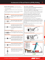
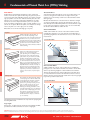
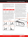
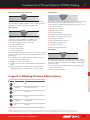
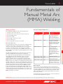
Consumables
8
Fundamentals of
Manual Metal Arc
(MMA) Welding
Welding Technique
Electrodes and Typical Applications
Successful MMA welding depends on the following factors:
1� Selection of the correct electrode
2� Selection of the correct size of the electrode for the job
3� Correct welding current
Name
AWS
Classification
BOC Smootharc 13
E6013
A premium quality electrode
for general structural and
sheet metal work in all
positions, including verticaldown using low carbon steels
BOC Smootharc 24
E7024
An iron powder electrode
for high speed welding for
H-V fillets and flat butt joints.
Medium to heavy structural
applications in low carbon
steels
BOC Smootharc 18
E7018-1
A premium quality, all
positional hydrogen
controlled electrode for
carbon steels in pressure
vessel applications and
where high integrity welding
is required; and for freemachining steels containing
sulphur
BOC Smootharc S 308L
E308L
BOC Smootharc S 316L
E316L
Rutile basic coated low
carbon electrodes for welding
austenitic stainless steel
BOC Smootharc S 309L
E309L
4� Correct arc length
5� Correct angle of electrode to work
6� Correct travel speed
7� Correct preparation of work to be welded.
Electrode Selection
As a general rule, the selection of an electrode is straight forward,
in that it is only a matter of selecting an electrode of similar
composition to the parent metal. However, for some metals there
is a choice of several electrodes, each of which has particular
properties to suit specific classes of work. Often, one electrode in
the group will be more suitable for general applications due to its all
round qualities.
The table below shows just a few of the wide range of electrodes
available from BOC, with their typical areas of application.
For example, the average welder will carry out most fabrication
using mild steel and for this material has a choice of various
standard BOC electrodes, each of which will have qualities
suited to particular tasks. For general mild steel work, however,
BOC Smootharc 13 electrodes will handle virtually all applications.
BOC Smootharc 13 is suitable for welding mild steel in all positions
using AC or DC power sources. Its easy striking characteristics and
the tolerance it has for work where fit-up and plate surfaces are not
considered good, make it the most attractive electrode of its class.
Continuous development and improvement of BOC Smootharc
13 have provided in-built operating qualities, which appeal to the
beginner and experienced operator alike. For further advice on the
selection of electrodes for specific applications, or to obtain a copy
of the ‘Welding Consumables: Selection Chart’, contact your local
BOC representative on 131 262.
Application
Rutile basic coated low
carbon electrode for welding
mild steel to stainless steel
and difficult to weld material
Electrode Size
The size of the electrode generally depends on the thickness of
the section being welded, and the thicker the section the larger the
electrode required. In the case of light sheet, the electrode size used
is generally slightly larger than the work being welded. This means
that, if 2.0 mm sheet is being welded, 2.5 mm diameter electrode is
the recommended size.
The following table gives the maximum size of electrodes that may
be used for various thicknesses of section.
WARNING W
elding can give rise to electric shock, excessive noise, eye and skin burns due to the arc rays, and a potential health hazard if you breathe in the emitted fumes and gases.
Read all the manufacturer’s instructions to achieve the correct welding conditions and ask your employer for the Materials Safety Data Sheets. Refer to www.boc.com.au or www.boc.co.nz
AU : IPRM 2007 : Section 8 : consumables
309
8
Fundamentals of Manual Metal Arc (MMA) Welding
Electrode Angle
Recommended Electrode Sizes
The angle that the electrode makes with the work is important to
ensure a smooth, even transfer of metal.
Average Thickness of Plate or
Section
Maximum Recommended
Electrode Diameter
1.5–2.0 mm
2.5 mm
The recommended angles for use in the various welding positions
are covered later.
2.0–5.0 mm
3.2 mm
Correct Travel Speed
5.0–8.0 mm
4.0 mm
≥8.0 mm
5.0 mm
The electrode should be moved along in the direction of the joint
being welded at a speed that will give the size of run required. At
the same time, the electrode is fed downwards to keep the correct
arc length at all times. As a guide for general applications, the table
below gives recommended run lengths for the downhand position.
Welding Current
Correct current selection for a particular job is an important factor
in arc welding. With the current set too low, difficulty is experienced
in striking and maintaining a stable arc. The electrode tends to stick
to the work, penetration is poor and beads with a distinct rounded
profile will be deposited.
Excessive current is accompanied by overheating of the electrode.
It will cause undercut and burning through of the material, and
will give excessive spatter. Normal current for a particular job
may be considered as the maximum, which can be used without
burning through the work, over-heating the electrode or producing
a rough spattered surface (i.e. the current in the middle of the
range specified on the electrode package is considered to be the
optimum).
In the case, of welding machines with separate terminals for
different size electrodes, ensure that the welding lead is connected
to the correct terminal for the size electrode being used. When
using machines with adjustable current, set on the current
range specified. The limits of this range should not normally be
exceeded. The following table shows the current ranges generally
recommended for BOC Smootharc 13.
Generally Recommended Current
Range for BOC Smootharc 13
Correct travel speed for normal welding applications varies between
approximately 100 and 300 mm per minute, depending on electrode
size, size of run required and the amperage used.
Excessive travel speeds lead to poor fusion, lack of penetration etc,
while too slow a rate of travel will frequently lead to arc instability,
slag inclusions and poor mechanical properties.
Run Length per Electrode – BOC Smootharc 13
Run Length (mm)
Electrode Size
(mm)
Electrode
Length (mm)
Minimum
Maximum
4.0
350
175
300
3.2
350
125
225
2.5
350
100
225
Correct Work Preparation
The method of preparation of components to be welded will
depend on equipment available and relative costs. Methods may
include sawing, punching, shearing, machining, flame cutting and
others.
Electrode Size (mm)
Current Range (Amp)
2.5
60–95
In all cases edges should be prepared for the joints that suit the
application.The following section describes the various joint types
and areas of application.
3.2
110–130
Types of Joints
4.0
140–165
Butt Welds
5.0
170–260
A butt weld is a weld made between two plates so as to give
continuity of section.
Arc Length
To strike the arc, the electrode should be gently scraped on the
work until the arc is established. There is a simple rule for the
proper arc length; it should be the shortest arc that gives a good
surface to the weld. An arc too long reduces penetration, produces
spatter and gives a rough surface finish to the weld. An excessively
short arc will cause sticking of the electrode and rough deposits
that are associated with slag inclusions.
For downhand welding, an arc length not greater than the diameter
of the core wire will be most satisfactory. Overhead welding
requires a very short arc, so that a minimum of metal will be lost.
Certain BOC electrodes have been specially designed for ‘touch’
welding. These electrodes may be dragged along the work and a
perfectly sound weld is produced.
Close attention must be paid to detail in a butt weld to ensure that
the maximum strength of the weld is developed. Failure to properly
prepare the edges may lead to the production of faulty welds, as
correct manipulation of the electrode is impeded.
Butt Welding
Reinforcement
Root Face
Weld Face
Root Gap
WARNING W
elding can give rise to electric shock, excessive noise, eye and skin burns due to the arc rays, and a potential health hazard if you breathe in the emitted fumes and gases.
Read all the manufacturer’s instructions to achieve the correct welding conditions and ask your employer for the Materials Safety Data Sheets. Refer to www.boc.com.au or www.boc.co.nz
310
AU : IPRM 2007 : Section 8 : consumables
8
Fundamentals of Manual Metal Arc (MMA) Welding
General Notes on Butt Welds
Two terms relating to the preparation of butt welds require
explanation at this stage. They are:
Root Face: the proportion of the prepared edge that has not
been bevelled (Land).
The first run in a prepared butt weld should be deposited with an
electrode not larger than 4.0 mm. The angle of the electrode for the
various runs in a butt weld is shown below.
Root Gap: the separation between root faces of the parts to be
joined.
It is necessary to maintain the root gap by tacking at intervals or by
other means, as it will tend to close during welding.
Various types of butt welds are in common use and their suitability
for different thickness of steel are described as follows:
All single ‘V’, single ‘U’ and square butt welds should have a backing
run deposited on the underside of the joint, otherwise 50% may be
deducted from the permissible working stress of the joint.
■
■
Square Butt Weld
The edges are not prepared, but are separated
slightly to allow fusion through the full thickness
of the steel. Suitable for plate up to 6 mm in
thickness.
Before proceeding with a run on the underside of a weld, it is
necessary to back-gouge or grind that side of the joint.
Butt welds should be overfilled to a certain extent by building
up the weld until it is above the surface of the plate. Excessive
reinforcement, however, should be avoided.
In multi-run butt welds, it is necessary to remove all slag and
surplus weld metal before a start is made on additional runs. This is
particularly important with the first run, which tends to form sharp
corners that cannot be penetrated with subsequent runs. Electrodes
larger than 4.0 mm are not generally used for vertical or overhead
butt welds.
Single ‘V’ Butt Weld
This is commonly used for plate up to 16 mm
in thickness and on metal of greater thickness
where access is available from only one side.
Double ‘V’ Butt Weld
The diagrams below indicate the correct procedure for welding
thick plate when using multiple runs.
Used on plate of 12 mm and over in thickness
when welding can be applied from both sides.
It allows faster welding and greater economy
of electrodes than a single ‘V’ preparation on
the same thickness of steel and also has less
tendency to distortion as weld contraction can
be equalised.
Bead Sequence for 1st and 2nd Layers
WELD BEADS
WELD BEADS
Butt Weld with Backing Material
LAYERS
When square butt welds or single ‘V’ welds
cannot be welded from both sides, it is desirable
to use a backing bar to ensure complete fusion.
LAYERS
Bead Sequence for Subsequent Layers
WELD BEADS
WELD BEADS
Single ‘U’ Butt Weld
Used on thick plates as an alternative to a single
‘V’ preparation. It has advantages in speed of
welding. It takes less weld metal than a single ‘V’,
there is less contraction and there is, therefore,
a lessened tendency to distortion. Preparation
is more expensive than in the case of a ‘V’, as
machining is required. This type of joint is most
suitable for material over 40 mm in thickness.
WELD METAL
LAYERS
LAYERS
WELD BEADS
Welding Progression Angle
Double ‘U’ Butt Weld
LAYERS
WELD BEADS
1 Weld Metal
2 Workpiece
3
3 Electrode
4 Slag
5 Welding Direction
ELECTRODE
6 70–85° Angle
70˚ - 85˚
7 Arc
WELD POOL8 Weld Pool
For use on thick plate that is accessible for
welding from both sides. For a given thickness it
is faster, needs less weld metal and causes less
distortion than a single ‘U’ preparation.
Horizontal Butt Weld
WELD BEADS
WELD BEADS
LAYERS
WELD BEADS
ARC
1
4
8
ARC
5
WARNING W
elding can give rise to electric shock, excessive noise, eye and skin burns due to the arc rays, and a potential health hazard if you breathe in the emitted fumes and gases.
ELECTRODE
Read all the manufacturer’s
instructions to achieve the correct welding conditions and ask your employer for the Materials Safety Data Sheets. Refer to www.boc.com.au or www.boc.co.nz
DIRECTION OF WELDING
LAYERS
ELECTRODE
70˚ - 85˚
ERS
WELD BEADS
WELD POOL
WELD :BEADS
AU : IPRMSLAG
2007
Section 8 : consumables
WELD METAL
WELD BEADS
ARC
7
DIRECTION2 OF WELDING
WELD POOL
WELD BEADS
SLAG
WELD METAL
6
SLAG
The lower member in this case is bevelled to
WELD METAL
approximately 15° and the upper member
45°,
making an included angle
of
60°.
This
preparation
ELECTRODE
provides a ledge on the lower member, which
70˚ - 85˚
tends to retain the molten metal.
ERS
W
SLAG
WE
SLAG
WELD METAL
70˚ - 85˚
WELD POOL
SLAG
311
8
Fundamentals of Manual Metal Arc (MMA) Welding
Fillet Welds
Throat Thickness
A fillet weld is approximately triangular in section, joining two
surfaces not in the same plane and forming a lap joint, tee joint or
corner joint. Joints made with fillet welds do not require extensive
edge preparation, as is the case with butt welded joints, since the
weld does not necessarily penetrate the full thickness of either
member. It is, however, important that the parts to be joined be
clean, close fitting, and that all the edges on which welding is to be
carried out are square. On sheared plate, it is advisable to entirely
remove any ‘false cut’ on the edges prior to welding.
A measurement taken through the centre of a weld from the root
to the face, along the line that bisects the angle formed by the
members to be joined. Many countries use throat thickness rather
than leg length.
Fillet welds are used in the following types of joints:
‘T’ Joints
A fillet weld may be placed either on
one or both sides, depending on the
requirements of the work. The weld metal
should fuse into or penetrate the corner
formed between the two members. Where
possible, the joint should be placed in such
a position as to form a ‘Natural ‘V’ fillet’
since this is the easiest and fastest method
of fillet welding.
Effective throat thickness is a measurement on which the strength
of a weld is calculated. The effective throat thickness is based on a
mitre fillet (Concave Fillet Weld), which has a throat thickness equal
to 70% of the leg length. For example, in the case of a 20 mm fillet,
the effective throat thickness will be 14 mm.
Convex Fillet Weld
A fillet weld in which the contour of the weld metal lies outside
a straight line joining the toes of the weld. A convex fillet weld of
specified leg length has a throat thickness in excess of the effective
measurement.
Convex Fillet Weld
1
2
3
4
5
6
1
2
3
4
5
Lap Joints
In this case, a fillet weld may be placed
either on one or both sides of the
joint, depending on accessibility and the
requirements of the joint. However, lap
joints, where only one weld is accessible,
should be avoided where possible and
must never constitute the joints of tanks
or other fabrications where corrosion is
likely to occur behind the lapped plates. In
applying fillet welds to lapped joints, it is
important that the amount of overlap of
the plates be not less than five times the
thickness of the thinner part. Where it is
required to preserve the outside face or
contour of a structure, one plate may be
joggled.
Corner Joints
The members are fitted as shown, leaving
a ‘V’-shaped groove in which a fillet weld
is deposited. Fusion should be complete
for the full thickness of the metal. In
practice, it is generally necessary to have
a gap or a slight overlap on the corner.
The use of a 1.0–2.5 mm gap has the
advantage of assisting penetration at the
root, although setting up is a problem. The
provision of an overlap largely overcomes
the problem of setting up, but prevents
complete penetration at the root and
should therefore be kept to a minimum
(i.e. 1.0–2.5 mm).
The following terms and definitions are important in specifying and
describing fillet welds.
Actual Throat
Effective Throat
Convexity
Leg
Size
Theoretical Throat
4 5
6
Concave Fillet Weld
A fillet in which the contour of the weld is below a straight line
joining the toes of the weld. It should be noted that a concave fillet
weld of a specified leg length has a throat thickness less than the
effective throat thickness for that size fillet. This means that, when
a concave fillet weld is used, the throat thickness must not be less
than the effective measurement. This entails an increase in leg length
beyond the specified measurement.
Concave Fillet Weld
1 2
1
2
3
4
5
6
3
5
4
4
Actual Throat
Effective Throat
Concavity
Leg
Size
Theoretical Throat
5
6
Leg Length
A fusion face of a fillet weld, as shown below. In Australia and NZ,
specifications for fillet weld sizes are based on leg length.
WARNING W
elding can give rise to electric shock, excessive noise, eye and skin burns due to the arc rays, and a potential health hazard if you breathe in the emitted fumes and gases.
Read all the manufacturer’s instructions to achieve the correct welding conditions and ask your employer for the Materials Safety Data Sheets. Refer to www.boc.com.au or www.boc.co.nz
312
AU : IPRM 2007 : Section 8 : consumables
8
Fundamentals of Manual Metal Arc (MMA) Welding
The size of a fillet weld is affected by the electrode size, welding
speed or run length, welding current and electrode angle. Welding
speed and run length have an important effect on the size and shape
of the fillet, and on the tendency to undercut.
Insufficient speed causes the molten metal to pile up behind the arc
and eventually to collapse. Conversely, excessive speed will produce
a narrow irregular run having poor penetration, and where larger
electrodes and high currents are used, undercut is likely to occur.
Fillet Weld Data
Nominal Fillet
Size (mm)
Min.Throat
Thickness (mm)
Plate Thickness
(mm)
Electrode
Size (mm)
5.0
3.5
5.0–6.3
3.2
6.3
4.5
6.3–12
4.0
8.0
5.5
8.0–12 and over
5.0
10.0
7.0
10 and over
4.0
Selection of welding current is important. If it is too high, the weld
surface will be flattened and undercut accompanied by excessive
spatter is likely to occur. Alternatively, a current which is too low
will produce a rounded narrow bead with poor penetration at the
root. The first run in the corner of a joint requires a suitably high
current to achieve maximum penetration at the root. A short arc
length is recommended for fillet welding. The maximum size fillet
which should be attempted with one pass of a large electrode is
8.0 mm. Efforts to obtain larger leg lengths usually result in collapse
of the metal at the vertical plate and serious undercutting. For
large leg lengths, multiple run fillets are necessary. These are built
up as shown below. The angle of the electrode for various runs in a
downhand fillet weld is also shown.
Multi-run (multi-pass) horizontal fillets have each run made using
the same run lengths (Run Length per Electrode Table). Each run
is made in the same direction, and care should be taken with the
shape of each, so that it has equal leg lengths and the contour of the
completed fillet weld is slightly convex with no hollows in the face.
Vertical fillet welds can be carried out using the upwards or
downwards technique. The characteristics of each are: Upwards
– current used is low, penetration is good, surface is slightly convex
and irregular. For multiple run fillets, large single pass weaving runs
can be used. Downwards – current used is medium, penetration is
poor, each run is small, concave and smooth.
The downwards method should be used for making welds on thin
material only. Electrodes larger than 4.0 mm are not recommended
for vertical-down welding. All strength joints in vertical plates
10.0 mm thick or more should be welded using the upward
technique.This method is used because of its good penetration and
weld metal quality.The first run of a vertical-up fillet weld should
be a straight sealing run made with 3.2 mm or 4.0 mm diameter
electrode. Subsequent runs for large fillets may be either numerous
straight runs or several wide weaving runs.
Correct selection of electrodes is important for vertical welding.
In overhead fillet welds, careful attention to technique is necessary
to obtain a sound weld of good profile. Medium current is required
for best results. High current will cause undercutting and bad
shape of the weld, while low current will cause slag inclusions. To
produce a weld having good penetration and of good profile, a short
arc length is necessary. Angles of electrode for overhead fillets is
illustrated below.
Recommended Electrode Angles for Overhead Fillet Welds
Recommended Electrode Angles For Fillet Welds
1st Run
2nd Run
15˚
3rd Run
45˚
30˚
Multi-run Fillet
WARNING W
elding can give rise to electric shock, excessive noise, eye and skin burns due to the arc rays, and a potential health hazard if you breathe in the emitted fumes and gases.
Read all the manufacturer’s instructions to achieve the correct welding conditions and ask your employer for the Materials Safety Data Sheets. Refer to www.boc.com.au or www.boc.co.nz
AU : IPRM 2007 : Section 8 : consumables
313
8
Fundamentals of Manual Metal Arc (MMA) Welding
Welding Defects and Problems
Manual metal arc welding, like other welding processes, has welding
procedure problems that may develop and which can cause
defects in the weld. Some defects are caused by problems with the
materials. Other welding problems may not be foreseeable and may
require immediate corrective action. A poor welding technique and
improper choice of welding parameters can cause weld defects.
Wagon Tracks
Defects that can occur when using the shielded metal arc welding
process are slag inclusions, wagon tracks, porosity, wormhole
porosity, undercutting, lack of fusion, overlapping, burn through,
arc strikes, craters and excessive weld spatter. Many of these
welding technique problems weaken the weld and can cause
cracking. Other problems that can occur and which can reduce
the quality of the weld are arc blow, finger nailing and improper
electrode coating moisture contents.
Defects Caused by Welding Technique
Slag Inclusions
Top View Thru Transparent Bead
Wagon tracks are linear slag inclusions that run the longitudinal axis
of the weld. They result from allowing the slag to run ahead of the
weld puddle and by slag left on the previous weld pass. These occur
at the toe lines of the previous weld bead.
Slag inclusions occur when slag particles are trapped inside the weld
metal, which produces a weaker weld. These can be caused by:
■
erratic travel speed
■
too wide a weaving motion
■
slag left on the previous weld pass
■
too large an electrode being used
■
letting slag run ahead of the arc.
This defect can be prevented by:
Porosity
Porosity is gas pockets in the weld metal that may be scattered
in small clusters or along the entire length of the weld. Porosity
weakens the weld in approximately the same way that slag
inclusions do.
■
a uniform travel speed
Porosity may be caused by:
■
a tighter weaving motion
■
excessive welding current
■
complete slag removal before welding
■
rust, grease, oil or dirt on the surface of the base metal
■
using a smaller electrode
■
excessive moisture in the electrode coatings
■
impurities in the base metal
■
keeping the slag behind the arc, which is done by shortening the
arc, increasing the travel speed or changing the electrode angle.
■
■
too short an arc length, except when using low-hydrogen or
stainless steel electrodes
travel speed too high, which causes freezing of the weld puddle
before gases can escape.
This problem can be prevented by:
■
lowering the welding current
■
cleaning the surface of the base metal
■
redrying electrodes
■
changing to a different base metal with a different composition
■
using a slightly longer arc length
■
lowering the travel speed to let the gases escape
■
preheating the base metal, using a different type of electrode,
or both.
WARNING W
elding can give rise to electric shock, excessive noise, eye and skin burns due to the arc rays, and a potential health hazard if you breathe in the emitted fumes and gases.
Read all the manufacturer’s instructions to achieve the correct welding conditions and ask your employer for the Materials Safety Data Sheets. Refer to www.boc.com.au or www.boc.co.nz
314
AU : IPRM 2007 : Section 8 : consumables
8
Fundamentals of Manual Metal Arc (MMA) Welding
Wormhole Porosity (Piping Porosity)
Lack of Fusion
Wormhole porosity is the name given to elongated gas pockets.
The best method of preventing this is to lower the travel speed to
permit gases to escape before the weld metal freezes.
Lack of fusion is when the weld metal is not fused to the base metal.
This can occur between the weld metal and the base metal or
between passes in a multiple pass weld. Causes of this defect can be:
Undercutting
Undercutting is a groove melted in the base metal next
to the toe or root of a weld that is not filled by the
weld metal. Undercutting causes a weaker joint and
it can cause cracking. This defect is caused by:
■ excessive welding current
■
too long an arc length
■
excessive weaving speed
■
excessive travel speed.
■
excessive travel speed
■
electrode size too large
■
welding current too low
■
poor joint preparation
■
letting the weld metal get ahead of the arc.
Lack of fusion can usually be prevented by:
■
reducing the travel speed
■
using a smaller diameter electrode
■
increasing the welding current
■
better joint preparation
■
using a proper electrode angle.
Overlapping
On vertical and horizontal welds, it can also be caused by too large
an electrode size and incorrect electrode angles. This defect can. be
prevented by:
■
■
■
■
choosing the proper welding current for the type and size of
electrode and the welding position
holding the arc as short as possible
pausing at each side of the weld bead when a weaving technique
is used
using a travel speed slow enough so that the weld metal can
completely fill all of the melted out areas of the base metal.
Overlapping is the protrusion of the weld metal over the edge or
toe of the weld bead. This defect can cause an area of lack of fusion
and create a notch, which can lead to crack initiation. Overlapping is
often produced by:
■
■
too slow a travel speed, which permits the weld puddle to get
ahead of the electrode
an incorrect electrode angle.
Legend to Welding Position Abbreviations
Symbol
Abbreviation
Description
F
Flat
H/V-FILLET
Horizontal-Vertical Fillet
H
Horizontal
V
Vertical
V-DOWN
Vertical-Down
OH
Overhead
WARNING W
elding can give rise to electric shock, excessive noise, eye and skin burns due to the arc rays, and a potential health hazard if you breathe in the emitted fumes and gases.
Read all the manufacturer’s instructions to achieve the correct welding conditions and ask your employer for the Materials Safety Data Sheets. Refer to www.boc.com.au or www.boc.co.nz
AU : IPRM 2007 : Section 8 : consumables
315
8
Fundamentals of Manual Metal Arc (MMA) Welding
Coating Types
It is the composition of the coating that differentiates one type of
electrode from another and, to a degree, what type of application
it can be used for. MMA electrodes, with a solid wire core, are
generally categorised by the type of flux coating they employ.
There are three main groups of electrode coating: rutile, basic and
cellulosic, plus a less-widely-used acid type. The name of each group
is a description of the main constituent of the coating. Although not
strictly a coating type, iron-powder electrodes are often considered
as a separate group.
Electrodes for cutting, grooving and gouging, plus those for hardsurfacing, including tubular MMA electrodes, are not classified by
coating type.
Rutile Electrodes
Rutile electrodes have a coating that contains about 50% rutile sand
(a pure form of titanium dioxide), plus additions of ferro-manganese,
mineral carbonates and silicates, held together with approximately
15% sodium silicate, also known as waterglass. The rutile’s
characteristics include easy striking, stable arc, low spatter, good
bead profile and, generally, easy slag removal from the electrode.
The electrode can operate on both AC and DC currents and
can operate in all positions if the formulation of the coating is
so designed.
One negative aspect of these electrodes is that they produce a high
level of hydrogen, typically greater than 15ml / 100g of deposited
weld metal. This cannot be avoided, because they rely on a certain
amount of moisture being present in the coating to operate properly.
If the electrodes are dried too much, they will fail to function
properly.
Rutile-coated electrodes are manufactured for welding mild and
low-carbon steels. In this context, they are often referred to as
general-purpose or GP electrodes. Some low-alloy grades also
use rutile coatings. Rutile-type coatings, which are modifications
of those used for ferritic steels, are also used on many austenitic
stainless steel electrodes.
Basic Electrodes
Basic, or low-hydrogen, electrodes contain calcium carbonate and
calcium fluoride in place of the rutile sand and mineral silicates. This
makes them less easy to strike and more difficult to re-strike, due
to the very deep cup formed at the tip during operation. They also
have a poorer, more convex bead profile than rutile electrodes. The
slag is more difficult to remove than the rutile types, but they do
give better weld metal properties than rutile types, with a higher
metallurgical quality.
Basic electrodes are capable of being used on AC or DC currents
and can be used in multi-pass welds on materials of all thicknesses.
Basic electrodes do not rely on moisture to function properly, and
for the more critical applications should be used completely dry. It
is important to note that basic electrodes are only low‑hydrogen
electrodes if they have been correctly dried before use. This
conventionally involves re-drying in ovens on site in accordance
with manufacturers’ recommendations. Drying can reduce weld
metal hydrogen to less than 5ml / 100g, as can vacuum‑packing the
electrodes. These can be used straight from the packs without any
form of drying required. BOC Smootharc 16 and 18 electrodes are
supplied in hermetically sealed containers, which ensures that they
meet the H4 grade.
Basic-type electrodes for ferritic steels, with low-alloy additions to
the coatings or the core wire, allow a much wider use, including
sub-zero and elevated-temperature application. Basic coatings are
also widely used for electrodes for welding stainless steels, nickel
alloys, cast irons, copper and aluminium alloys, and for hard‑facing
applications.
Cellulosic Electrodes
Cellulosic electrodes contain a high proportion of organic material,
replacing all or some of the rutile sand. This produces a fierce, deep
penetrating arc and a faster burn-off rate. Cellulosic electrodes are
more prone to spatter than rutile types. Only carbon and some
low-alloy steels are made with a cellulosic coating and most run
only on DC+ polarity, but some are made that will also operate
on AC and DC-. They are truly all-positional electrodes in all sizes
and even larger diameters up to 6 mm will operate vertical‑down.
Cellulosic electrodes are used for root passes and pipeline welding.
It should be noted that celullosic electrodes generate high amounts
of hydrogen. This presents a risk of hydrogen-induced cracking if
correct welding procedures are not followed.
Acid Electrodes
Acid electrodes for mild steels have been largely replaced by rutile
types, but some are still produced by a few manufacturers. These
electrodes contain high amounts of iron oxide, are relatively easy
to use and give a voluminous glassy slag that detaches easily. They
are lower-strength products, so they are confined to use on nonstructural components.
Acid-rutile electrodes for stainless steel are now replacing
conventional rutile types. They are higher in silicon, which gives
improved operating and wetting characteristics, and they are much
more welder-friendly. They strike and re-strike readily and will
operate on AC and DC current. They produce low spatter levels
and an easily removed slag. However, they are prone to ‘start
porosity’ and need re-drying before use to avoid this.
Iron-powder Electrodes
Iron-powder electrodes are often considered an independent group
of consumables. As their name suggests, these electrodes contain
high levels of iron powder held within the coating – as the coating
melts, the iron powder creates more weld metal. This effectively
improves the productivity from the electrode, allowing either larger
or longer welds to be created from a single rod. The amount of iron
powder added depends on the consumable being produced, but it is
not uncommon for 75% of the core weight to be added.
The addition of the iron powder to the coating has the effect of
increasing the overall diameter of the electrode and reducing the
amount of fluxing agent present in the coating. With less fluxing
agent available, the slag coating tends to be thinner, so many of the
MMA electrode’s positional welding characteristics are lost. This
means that many of the electrodes can only be used in the flat or
horizontal-vertical (H-V) positions.
Coatings for iron-powder electrodes may be based on either the
rutile or basic systems.
WARNING W
elding can give rise to electric shock, excessive noise, eye and skin burns due to the arc rays, and a potential health hazard if you breathe in the emitted fumes and gases.
Read all the manufacturer’s instructions to achieve the correct welding conditions and ask your employer for the Materials Safety Data Sheets. Refer to www.boc.com.au or www.boc.co.nz
316
AU : IPRM 2007 : Section 8 : consumables
Fundamentals of Manual Metal Arc (MMA) Welding
8
Care and Conditioning of Consumables
Practical Considerations
Storage and Re-drying
MMA electrodes should be stored in dry, well-ventilated and
preferably heated stores. For critical applications it is also
recommended that they be held in temperature and humidity
controlled conditions, maintaining humidity below 60%RH (Relative
Humidity) and a temperature above the dew point to avoid
moisture condensing onto the electrodes. Electrodes held in dry
conditions will remain in prime condition for several years, but if the
coating absorbs moisture, this will lead to a gradual deterioration.
Evidence of deterioration includes the presence of white powdery
areas on the surface of the coating, cracks in the coating or missing
pieces of coating.
Electrodes with rutile or cellulosic coating require some moisture in
the coating to operate properly and should not be re-dried. If rutile
electrodes get wet, re-drying at about 80°C is all that is needed.
Cellulosic electrodes must not be dried. In some hot environments
they may need wetting to function efficiently.
Basic coated electrodes need to be dry to give low-hydrogen weld
metal. Before use, these electrodes should be re-dried according
to manufacturers’ recommendations, put in holding ovens and
then transferred to the workstations in heated quivers until
needed.Vacuum-packed basic electrodes can be used straight from
the packet.
Electrodes for non-ferrous alloys and stainless steel always need to
be completely dry before use and should be treated in accordance
with manufacturers’ requirements.
Welding Parameters
Some electrodes will operate satisfactorily on AC or DC current
and, for AC operation, manufacturers will recommend a minimum
OCV (Open Circuit Voltage) to initiate a welding arc with
the electrode.
WARNING W
elding can give rise to electric shock, excessive noise, eye and skin burns due to the arc rays, and a potential health hazard if you breathe in the emitted fumes and gases.
Read all the manufacturer’s instructions to achieve the correct welding conditions and ask your employer for the Materials Safety Data Sheets. Refer to www.boc.com.au or www.boc.co.nz
AU : IPRM 2007 : Section 8 : consumables
317