1
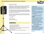
MegaVox Pro Public Address System Owners Manual
MADE IN USA
A Message from the President
Congratulations on purchasing an Anchor Audio sound system, the choice of thousands
of satisfied customers including the White House, prestigious universities, school
districts nationwide, police and fire departments, and all branches of the U.S. Military.
Our products are made of the finest materials and built with pride in the U.S.
We’ve incorporated the latest technology into your sound system yet kept it simple to
use. Just take a few minutes to review this manual to ensure the maximum enjoyment
of your Anchor system. Or, you can view a demonstration video complete with a trouble
shooting section at www.anchoraudio.com.
Feel free to call our friendly customer support staff at 1-800-ANCHOR1
with any questions. We love to hear from our customers.
SIX YEAR WARRANTY
GETTING STARTED
Please check your new unit carefully for any
damage which may have occurred during shipment.
Each Anchor product is carefully inspected at the
factory and packed in specially designed boxes for
safe transport.
Notify the freight carrier immediately of any damage
to the shipping box or product. Repack the unit
in the original box and wait for inspection by the
carrier’s claim agent. Notify your dealer of the
pending freight claim.
NOTE: All damage claims must be made with freight carrier!
RETURNING SYSTEMS FOR SERVICE
OR REPAIR
BASIC SYSTEM OPERATION / BACK PANEL .............................................................................. 2
For service or repair, please contact the dealer
you purchased your system from, call us at 1-800262-4671, or visit www.AnchorAudio.com, Contact
Us page. Our tech support team will issue an RA
number for warranted systems, after which, you can
ship the item(s) to Anchor for repair. All shipments
to Anchor Audio must include an RA number and
must be shipped prepaid. C.O.D. shipments and
shipments without an RA number will be refused
and returned at your expense.
CONNECTING PA SYSTEM / CONTROLLING FEEDBACK ............................................................. 3
IMPORTANT: Save the shipping box & packing materials,
they were specially designed to ship your unit!
Janet Jacobs, President
on behalf of all Anchor employees
CONTENTS
GETTING STARTED................................................................................................................... 1
OPERATING THE BUILT-IN UHF WIRELESS RECEIVER.................................................................. 4
OPERATING THE WIRELESS MICROPHONE/TRANSMITTER.......................................................... 5
OPERATING BLUETOOTH TRANSMITTER.................................................................................... 6
CARING FOR YOUR BATTERY.................................................................................................... 7
The MegaVox Pro PA system comes with a six year warranty,
Anchor Audio Bluetooth comes with a six year warranty,
and all Anchor Audio batteries and wireless come with a
two year warranty.
IMPORTANT SAFETY INSTRUCTIONS................................................................................... 8 - 9
HAVING TROUBLE WITH YOUR SOUND SYSTEM? / TECHNICAL SPECS...................................... 10
For System Setup & Operation Videos Visit Our Website: www.anchoraudio.com
1
MegaVox Pro Public Address System Owners Manual
MADE IN USA
SIX YEAR WARRANTY
BASIC SYSTEM OPERATION
BACK PANEL OF MEGA-8000U2
NOTE: Fully Charge Batteries Before First Use!
1. Before turning the systems power on: Set all Input
Level Controls
2. Plug a microphone into a MIC jack and/or a line-level
audio source into the LINE IN jack
3. Switch POWER to ON - The red BATTERY LED will turn
on (If the light flashes or stays off charge the battery)
4. Slowly increase the Level Controls for the input jacks
used to desired volume level
IMPORTANT: Make all connections with shielded cables to avoid
hum, buzzing or interference.
SPEAKER STAND SETUP
1. Loosen the Lower Collar Knob
2. Separate the stand legs until the leg support Cross
Braces are parallel to the floor
3. Tighten the Lower Collar Knob
4. Loosen the Upper Collar Knob and extend the
center pole
5. Adjust height and retighten the Upper Collar Knob
6. Place your Anchor sound system on the stand
BLUETOOTH RECEIVER
WIRELESS RECEIVERS
(see page 4)
(see page 6)
8000
PAIRING
WIRELESS LEVEL CONTROLS
RX
RX
LINE IN
LEVEL CONTROL
WIRELESS 1
MIC/SIGNAL ALERT
LEVEL CONTROL
RX
RX
WIRELESS 2
LINE OUT - OUTPUT JACK
1/4” Phone - Unbalanced,
combined output of all active
system inputs
POWER SWITCH
MIC - INPUT JACK
SIGNAL ALERT
1/4” Phone - Unbalanced,
low impedance, no
phantom power
MIC 1
MIC 2
LINE IN
LINE OUT
(Output is post source level;
any volume fluctuations for a
specific input will affect this
output signal level)
CHARGER INPUT JACK
19 VDC
(60 WATTS MAX)
800.262.4671
UPPER
COLLAR
KNOB
LOWER
COLLAR KNOB
MegaVox Pro Bluetooth Back Panel Silkscreen Artwork
SPEAKER
July 30, OUT
2014
OUTPUT JACK
Anchor Audio, Inc.
BATTERY CHARGE
INDICATOR
LINE IN - INPUT JACK
1/4” Phone - For any line-level
signal source: IPOD/CD/MP3
players, musical instruments, etc.
CROSS BRACES
217-0309-000 rev. E
(Reference dwg# 216-0309-000 for dimension & material info)
1/4” Phone - Drives the
MEGA-8001 unpowered
companion speaker
Using companion speaker
will decrease battery service
time requiring more
frequent charging
CAUTION: The signal alert sound can produce VERY high or harmful sound pressure levels that can cause hearing damage.
For System Setup & Operation Videos Visit Our Website: www.anchoraudio.com
2
MegaVox Pro Public Address System Owners Manual
SIX YEAR WARRANTY
CONNECTING TWO OR MORE MEGAVOX PRO PA SYSTEMS
UNPOWERED MEGAVOX PRO COMPANION SPEAKER (MEGA-8001)
Connect one end of a speaker cable (SC-50) to the SPKR OUT jack on the back of a
powered MegaVox PRO PA system.
The other end connects to the jack labeled IN on the back of a MegaVox PRO
unpowered companion speaker.
MADE IN USA
CORRECT SYSTEM PLACEMENT
WRONG SYSTEM PLACEMENT
NOTE: AC power is not required for an unpowered companion speaker.
POWERED MEGAVOX PRO PA SYSTEMS WITH LINE OUT
Connect speaker cable (SC-50) from LINE OUT on first powered MegaVox PRO to
LINE IN on second powered MegaVox PRO. Set volume level of the second system to
maximum, this gives full volume control to the first or primary PA system.
Daisy-Chaining
Use the Line Out method above to connect up to six powered MegaVox PRO PA
Systems. Make all connections with power off.
Set volume level to maximum on all secondary systems so the primary unit Level
Control sets the volume for the entire chain.
To avoid speaker popping, which can cause damage, power speakers on in order,
primary unit first, and power speakers off in reverse order, primary unit last.
EX-50PP CABLE
FIRST POWERED MEGAVOX PRO
8000
PAIRING
RX
RX
WIRELESS 1
8000
RX
RX
WIRELESS 2
PAIRING
RX
RX
WIRELESS 1
RX
RX
SIGNAL ALERT
MIC 1
MIC 2
LINE IN
LINE OUT
WIRELESS 2
SIGNAL ALERT
MIC 1
MIC 2
LINE IN
CONTROLLING FEEDBACK
Feedback, a howling noise or shrill sound, is self-generated by the sound system. It’s caused by
a microphone picking up the sound coming from the speaker and then re-amplifying it. Once a
feedback loop starts, it continues until the system is adjusted.
FEEDBACK CAUSES
• Microphone too close, pointing towards
or in front of speaker
• Volume setting is too loud for room
• Sound reflecting off hard surfaces
AVOIDING & ELIMINATING FEEDBACK
• Point microphone in a different direction
• Keep microphone away from the speaker
• Place speaker in FRONT of the microphone
• Reduce the sound system volume levels
CAUTION: Feedback can damage your equipment & may be hazardous to hearing.
LINE OUT
19 VDC
(60 WATTS MAX)
800.262.4671
MegaVox Pro Bluetooth Back Panel Silkscreen Artwork
217-0309-000 rev. E
(Reference dwg# 216-0309-000 for dimension & material info)
Anchor Audio, Inc.
19 VDC
(60 WATTS MAX)
800.262.4671
MegaVox Pro Bluetooth Back Panel Silkscreen Artwork
217-0309-000 rev. E
(Reference dwg# 216-0309-000 for dimension & material info)
Anchor Audio, Inc.
July 30, 2014
July 30, 2014
SECOND POWERED
MEGAVOX PRO
For System Setup & Operation Videos Visit Our Website: www.anchoraudio.com
3
MegaVox Pro Public Address System Owners Manual
MADE IN USA
SIX YEAR WARRANTY
DIVERSITY WIRELESS BY ANCHOR AUDIO
Anchor Audio UHF wireless is a 16 channel, diversity wireless system that receives signals with two independent antennae. With diversity
wireless the receiver processes the stronger signal, effectively minimizing dropouts and interference from other transmitting sources.
The antennae are mounted internally so there are no obstructions or risk of damage. The wireless operates between 540 - 570 MHz,
as of August 1, 2014.
CHANNEL SELECTION - BUILT-IN RECEIVER
Select a channel, set the built-in receiver & microphone transmitter
to that channel before using your wireless system.
1. Choose any available wireless channel (see page 5 for
transmitter instructions)
2. Set the Wireless Channel Selection Knob to the channel you
choose in step 1
CHANNEL SELECTION DIAL
RX INDICATOR LIGHTS
If you have two wireless receivers repeat above for the second receiver.
Remember, each receiver/transmitter pair must be set to different
channels to avoid interference.
NOTE: Ongoing wireless interference? The frequency you selected may be in use by other systems in the area!
Change channels until you find a clear frequency!
For System Setup & Operation Videos Visit Our Website: www.anchoraudio.com
4
MegaVox Pro Public Address System Owners Manual
MADE IN USA
OPERATING THE WIRELESS MICROPHONE/TRANSMITTER
SIX YEAR WARRANTY
CHANNEL SELECTION - HANDHELD TRANSMITTER
1. Unscrew battery cover on bottom of microphone
2. Set the CHANNEL SELECTOR dial to match the channel setting
of your receiver
3. Replace battery cover and tighten firmly
CHANNEL SELECTION - BODY-PACK TRANSMITTER
1. The channel selection dial is located on the side of the transmitter
2. Set the CHANNEL selection dial to match the channel setting of the receiver
NOTE: When using dual wireless, each microphone must be set to a different channel!
USING YOUR WIRELESS MICROPHONES
After you have set the transmitter channel (see above) you are ready to use your wireless microphone:
1. Body-pack transmitter users must insert
the mic plug into the transmitter jack
marked MIC
2. Push the transmitter power button for two seconds until ON (The red LED will stay on when
the mic is turned on. If the red LED flashes, the
battery is low)
3. Turn the MegaVox power switch to ON
4. The RX indicators will light (only one indicator
will light at a time) when the wireless signal is
being transmitted and received
CAUTION: Harmful feedback may occur when walking in front of a sound system or speaker with a wireless microphone. Always point microphone away from speakers!
REPLACE BATTERY - HANDHELD TRANSMITTER
1. Unscrew battery cover on bottom of microphone
2. Replace old batteries with two fresh size ‘AA’
alkaline batteries
3. Replace battery cover and tighten firmly
REPLACE BATTERY - BODY-PACK TRANSMITTER
1. Slide open battery cover on front of transmitter
2. Replace old batteries with two fresh size ‘AA’
alkaline batteries
3. Replace battery cover by sliding firmly into place
For System Setup & Operation Videos Visit Our Website: www.anchoraudio.com
5
MegaVox Pro Public Address System Owners Manual
OPERATING THE BLUETOOTH TRANSMITTER
POWERING UP THE BLUETOOTH
1. Turn on the Bluetooth with the volume knob (it will make a boot up
noise).
2. Before hooking up your device, take a moment to go over what the
different LED light signals mean:
a.
No light: indicates either Blutooth is off, or it is in sleep mode, and cannot connect
b.
Blinking light: indicates pairing mode, this is when you should connect
c.
Solid light: indicates connection, your device is connected
MADE IN USA
VOLUME/POWER KNOB
SIX YEAR WARRANTY
PAIRING
VOLUME
INDICATOR LIGHT
PAIRING A DEVICE
1. Press the pairing button (it will acknowledge pairing mode with a beep)
this mode will last 90 seconds. If no device is paired within the 90
seconds, the Bluetooth will enter sleep mode.
2. When the Bluetooth module is in pairing mode, it is discoverable and
will show up on the selection list of your Bluetooth enabled device.
3. Select the Bluetooth titled “Anchor Audio” to pair your device with the
Anchor Audio Sound System.
4. If a previously paired device is in range and discoverable, the unit
should automatically make a connection, however this may depend on
your individual device.
5. When the device has successfully connected to the Bluetooth, the
Bluetooth module will beep to signify connection and the Blue LED will
become solid.
6. Now you can play audio from your Bluetooth device to the Anchor Audio
Portable Sound System. You can adjust volume by using the Bluetooth
module’s knob, as well as the volume control on your device.
NOTE: All Anchor Audio Sound System Bluetooth connections will be
named “Anchor Audio”, so if your using multiple systems, be sure to
keep track of each connection.
PAIRING BUTTON
Frequently Asked Questions:
What is the range of Anchor Audio Bluetooth?
The Anchor Audio Bluetooth range is 100 ft. line of sight.
My Sound System is auto-connecting to a device, but I don’t know which one. Can
I disconnect directly from the Sound System?
Yes, if your unit is auto-connecting to a device that you cannot identify (because for example,
you’re in a room with other people who have connected to the unit in the past), you may
need to manually disconnect that pair from the Sound System itself. Just hold the ‘pairing’
button for two seconds, and the Sound System will disconnect from the device it is currently
connected to, and immediately go into pairing mode.
What kind of modes can my phone be in that allow the Bluetooth connection to
still work?
Bluetooth will work in modes such as Airplane mode and Do Not Disturb (or the equivalent).
Just be sure to still have your Bluetooth setting turned on. To simplify the process, put your
phone in the desired mode first, and then secure the Bluetooth connection, as moving into
these modes may cause disconnection.
What happens if I get a phone call?
Incoming and outgoing calls should pause the audio stream. The audio from the call should
not be transmitted via Bluetooth. To avoid interrupting audio, set device in Airplane mode,
then enable Bluetooth, ensure your connected, and you should not encounter any interruptions in your audio stream.
*Bluetooth connection and behavior may depend on your individual device settings and capabilities, all testing was
done using an Apple iPhone.
For System Setup & Operation Videos Visit Our Website: www.anchoraudio.com
6
MegaVox Pro Public Address System Owners Manual
MADE IN USA
SIX YEAR WARRANTY
CARING FOR YOUR BUILT-IN battery
It is very important that you fully charge the battery in your new
pa system before the first time its used. To preserve battery life it
is also recommended that the battery be fully charged as soon as
possible after every use regardless of the length of operation.
UNDERSTANDING THE BATTERY LEVEL INDICATOR
LED Flashing Red: Battery charge is very low, in 15-30 minutes
the Battery Protection Circuit will turn the system off.
LED Off: Battery is completely drained and must be charged.
NOTE: System can be used while batteries charge!
OPERATING IN AC MODE
Plug your sound system into an AC outlet. Operate as normal
while charging the built-in battery at the same time. The Charger
LED will light during charging and flash when the battery is fully
charged.
BATTERY SERVICE TIME
With the battery fully charged you can expect approx.:
8-12 hrs @ Medium Volume 3-6 hrs @ Full Volume
of continuous music input (longer for speech). Service time will
vary depending on control settings and use of accessories
(built-in wireless receivers and/or a companion speaker).
IMPORTANT:
CHARGING YOUR BUILT-IN battery
An automatic charging system is built-in to your MegaVox
PRO PA System. It is designed to properly charge and
maintain the systems built-in battery. To charge battery:
1. Plug the power cord into your
sound system
2. Plug the other end of the cord into
AC outlet - Charger LED will stay on during
charging
3. Battery fully charged in approximatly
15 - 20 hrs - Charger LED will flash
When in AC mode the system automatically transfers
power from the battery charger to the power amplifier at
high volume output, causing the Charger LED to flicker.
SYSTEM STORAGE & BATTERIES
Always store your sound system with the battery fully
charged. For extended periods of storage leave the
system plugged into an AC outlet. If this is not possible,
charge the system at least once each month for a
minimum of 24 hours.
For longer battery life always store your system
with batteries fully charged!
Waste electrical and electronic products must not be disposed
of with household waste. Please recycle where facilities exist.
Check with your Local Authority or Retailer for recycling advice.
For System Setup & Operation Videos Visit Our Website: www.anchoraudio.com
7
MegaVox Pro Public Address System Owners Manual
MADE IN USA
SIX YEAR WARRANTY
European Union CE Mark European Union CE Mark
Waste Electrical and Electronic Equipment (WEEE)
The presence of the CE Mark on Anchor equipment means that it has
been designed, tested and certified as complying with all applicable
European Union (CE) regulations and recommendations.
This symbol on the product or on its packaging indicates that this
product must not be disposed of with regular waste. Instead, it is the
user responsibility to dispose of waste equipment according to the local
laws. The separate collection and recycling of the waste equipment
at the time of disposal will help to conserve natural resources and
ensure that it is recycled in a manner that protects human health and
the environment. For information about where the user can drop off
the waste equipment for recycling, please contact your local Anchor
representative. See Section for instructions on how to disassemble the
equipment for recycling purposes.
Figure WEEE Directive Symbol
Direct current symbol
Figure DC Voltage Symbol
This international symbol implies a Direct voltage or current.
Inspection for Damage
Fuse Symbol
Figure Fuse Symbol
The fuse symbol in the figure above identifies the fuse location on
the Anchor System. (Not required if not user replaceable)
The Model MegaVox Pro is carefully packaged at the factory to
minimize the possibility of damage during shipping. Inspect the box
for external signs of damage or mishandling. Inspect the contents for
damage. If there is visible damage to the instrument upon receipt,
inform the shipping company and Anchor Inc. immediately.
Inspection for Damage
Do not attempt to operate this equipment if there is
evidence of shipping damage or you suspect the unit is
damaged. Damaged equipment may present additional
hazards to you. Contact Anchor technical support
for advice before attempting to plug in and operate
damaged equipment.
On Symbol
The On Symbol in the figure above represents a power switch position
on the Anchor System. This symbol represents a Power On condition.
Figure On Symbol
O
Figure Off Symbol
Warning: To reduce the risk of fire or electric shock, do not expose this apparatus to rain or
moisture, apparatus shall not be exposed to dripping or splashing and no objects filled with
liquids, such as vases, shall be placed on the apparatus.
Off Symbol
The Off Symbol in the figure above represents a power switch position
on the Anchor System. This symbol represents a Power Off condition.
– minimum distances around the apparatus for sufficient ventilation; the ventilation should
not be impeded by covering the ventilation openings with items, such as newspapers, tablecloths, curtains, etc.; no naked flame sources, such as lighted candles, should be placed on
the apparatus.
– attention should be drawn to the environmental aspects of battery disposal; the use of
apparatus in tropical and/or moderate climates.
-Equipment may be located above or below this apparatus, but some equipment (like large
amplifiers) may cause an unacceptable amount of hum or may generate too much heat and
degrade the performance of this apparatus.
For System Setup & Operation Videos Visit Our Website: www.anchoraudio.com
8
MegaVox Pro Public Address System Owners Manual
MADE IN USA
SIX YEAR WARRANTY
Important Safety Instructions
1) Read Instructions – All the safety and operation instructions should be read before the product is operated.
2) Retain Instructions – The safety and operating instructions should be retained for future
reference.
3) Heed Warnings- All warnings on the product and in the operating instructions should be adhered to.
4) Follow Instructions – All operating and use instructions should be followed.
5) Cleaning – Unplug this product from the wall outlet before cleaning. Do not use liquid
cleaners or aerosol cleaners. Use a damp cloth for cleaning.
Exception: A product that is meant for uninterrupted service and that for some specific
reason, such as the possibility of the loss of an authorization code for the CATV converter,
is not intended to be unplugged by the user for cleaning or any other purpose, may
exclude the reference to unplugging the product in the cleaning description otherwise in
above 5).
6) Attachments – Do not use attachments not recommended by the product manufacturer
as they may cause hazards.
7) Water and Moisture – Do not use this product near water – for example, near a bath tub,
wash bowl, kitchen sink, or laundry tub; in a wet basement; or near a swimming pool;
and the like.
8) Accessories – Do not place this product on an unstable cart, stand, tripod, bracket, or
table. The product may fall, causing serious injury to a child or adult, and serious damage
to the product. Use only with a cart, stand, tripod, bracket, or table recommended by the
manufacturer, or sold with the product. Any mounting of the product should follow the
manufacturer’s instructions, and should use a mounting accessory recommended by the
manufacturer.
9) A product and cart combination should be moved with care. Quick stop, excessive force,
and uneven surfaces may cause the product and cart combination to overturn.
10) Ventilation – Slots and openings in the cabinet are provided for ventilation and to ensure
reliable operation of the product and to protect it from overheating, and these openings
must not be blocked or covered. The openings should never be blocked by placing the
product on a bed, sofa, rug, or other similar surface. This product should not be placed in
a build-in installation such as a bookcase or rack unless proper ventilation is provided or
the manufacturer’s instructions have been adhered to.
11) Power Sources – This product should be operated only from the type of power source
indicated on the marking label. If you are not sure of the type of power supply to your
home, consult your product dealer or local power company. For products intended to
operate from battery power, or other sources, refer to the operating instructions.
12) Grounding or Polarization – This product may be equipped with a polarized alternatingcurrent line plug (a plug having one blade wider than the other). This plug will fit into
the power outlet only one way. This is a safety feature. IF you are unable to insert the
plug fully into the outlet, try reversing the plug. If the plug should still fail to fit, contact
your electrician to replace your obsolete outlet. Do not defeat the safety purpose of the
polarized plug.
13) Power-Cord Protection – Power-supply cords should be routed so that they are not likely
to be walked on or pinched by items placed upon or against them, paying particular
attention to cords at plugs, convenience receptacles, and the point where they exit from
the product.
14) Protective Attachment Plug – The product is equipped with an attachment plug having
overload protection. This is a safety feature. See Instruction Manual for replacement or
resetting of protective device. If replacement of the plug is required, be sure the service
technician has used a replacement plug specified by the manufacturer that has the same
overload protection as the original plug.
15) Outdoor Antenna Grounding – If an outside antenna or cable system is connected to
the product, be sure the antenna or cable system is grounded so as to provide some
protection against voltage surges and built-up static charges. Article 810 of the National
Electrical Code, ANSI/NFPA 70, provides information with regard to proper grounding of
the mast and supporting structure grounding of the lead in wire to an antenna discharge
unit, size of grounding conductors, location of antenna-discharge unit, connection of
grounding electrodes, and requirements for the grounding electrode. See Figure A.
16) Lightning – For added protection this product during lightning storm, or when it is left
unattended and unused for long periods of time, unplug it from the wall outlet and
disconnect the antenna or cable system. This will prevent damage to the product due to
lightning and power-line surges.
17) Power Lines – An outside antenna system should not be located in the vicinity of
overhead power lines or other electric light or power circuits, or where it can fall into
such power lines or circuits. When installing an outside antenna system, extreme care
should be taken to keep from touching such power lines or circuits as contact with them
might be fatal.
18) Overloading – Do not overload wall outlets, extension cords, or integral convenience
receptacles as this can result in a risk of fire or electric shock.
19) Object and Liquid Entry – Never push objects of any kind into this product through
openings as they may touch dangerous voltage points or short-out parts that could result
in a fire or electric shock. Never spill liquid of any kind on the product.
20) Servicing – Do not attempt to service this product yourself as opening or removing
covers may expose you to dangerous voltage or other hazards. Refer all servicing to
qualified service personnel.
21) Damage Requiring Service – Unplug this product from the wall outlet and refer servicing
to qualified service personnel under the following conditions:
a.When the power-supply cord or plug is damaged.
b.If liquid has been spilled, or objects have fallen into the product.
c. If the product has been exposed to rain or water.
d.If the product does not operate normally by following the operating
instructions. Adjust only those controls that are covered by the operating
instructions as an improper adjustment of other controls may result in damage and will often require extensive work by a qualified technician to restore the product to its normal operation.
e.If the product has been dropped or damaged in any way.
f. When the product exhibits a distinct change in performance – this indicates a need for service.
22) Replacement Parts – When replacement parts are required, be sure the service
technician has used replacement parts specified by the manufacturer or have the same
characteristics as the original part. Unauthorized substitutions may result in fire, electric
shock, or other hazards.
23) Safety Check – Upon completion of any service or repairs to this product, ask the service
technician to perform safety checks to determine that the product is in proper operation
condition.
24) Wall or Ceiling Mounting – The product should be mounted to a wall or ceiling only as
recommended by the manufacturer.
25 Heat – The product should be situated away from heat sources such as radiators, heat
registers, stoves, or other products (including amplifiers) that produce heat.
For System Setup & Operation Videos Visit Our Website: www.anchoraudio.com
9
MegaVox Pro Public Address System Owners Manual
MADE IN USA
HAVING TROUBLE with YOUR pa SYSTEM?
CONDITION
No Sound (power LED = OFF)
Charge Indicator Not On
No Sound (power LED = ON)
Shortened Battery Life
Distorted Sound
Excessive Hum or Noise
SIX YEAR WARRANTY
POSSIBLE CAUSE
• power switch is in OFF position
• batteries are fully discharged - LED may flash briefly
• confirm proper charger - replace if necessary
• no output from source
• input cable unplugged or
• input volume control is low or off
• short in external speaker cable or speaker
• total external speaker impedance < 8Ω
• battery is not fully charged or need to be replaced
• poor connection on input cable
• input signal too strong
• input cable not shielded
HAVING TROUBLE WITH YOUR WIRELESS SYSTEM? (Wireless Models Only)
CONDITION
No Sound (RX ON Indicator = ON)
No Sound (RX ON Indicator = OFF)
POSSIBLE CAUSE
• wireless volume control is to low or off
• no mic plugged into belt-pack transmitter
• sound system not turned on
• transmitter power switch turned off
• low battery or no battery in transmitter
• transmitter and receiver are not on the same channel
NEED MORE HELP? MegaVox Pro PA Setup & Operation Videos!
Visit Our Website: www.anchoraudio.com
MEGAVOX PRO TECHNICAL SPECIFICATIONS
Rated Peak Power
20 watts
Max SPL @ Rated Power 119 dB @ 1 meter
Frequency Response
400 Hz – 10 kHz
Charger (RC-6000)
18V DC/universal input
(100Vac – 240Vac, 50 – 63Hz)
Battery
12 volt rechargeable, 5 AH
Dimensions (HWD)
13” x 9” x 14” (33 x 23 x 36 cm)
Weight
15 lbs / 6.8 Kg
Inputs
Line
Hi-Z, unbalanced, 1/4”-phone
Mic 1
Lo-Z, unbalanced, 1/4”-phone
(used for wireless on
MEGA-6000U1)
Mic 2
Lo-Z, unbalanced, 1/4”-phone
Outputs
Line (post fader)
Lo-Z, 1/4”-phone
Speaker Out
Anchor Audio Customer Service
800.262.4671
FOR ADDITIONAL INFORMATION
visit www.anchoraudio.com
4Ω, unswitched, 1/4”-phone
(Specifications Subject to Change Without Notice)
For System Setup & Operation Videos Visit Our Website: www.anchoraudio.com
10