1
Dialogic ® DSI SPCI Network Interface Boards
Programmer's Manual
April 2012
U03HSP
www.dialogic.com
Copyright and Legal Notice
Copyright © 1993-2012 Dialogic Inc. All Rights Reserved. You may not reproduce this document in whole or in part
without permission in writing from Dialogic Inc. at the address provided below.
All contents of this document are furnished for informational use only and are subject to change without notice and do
not represent a commitment on the part of Dialogic Inc. and its affiliates or subsidiaries (“Dialogic”). Reasonable effort
is made to ensure the accuracy of the information contained in the document. However, Dialogic does not warrant the
accuracy of this information and cannot accept responsibility for errors, inaccuracies or omissions that may be
contained in this document.
INFORMATION IN THIS DOCUMENT IS PROVIDED IN CONNECTION WITH DIALOGIC® PRODUCTS. NO LICENSE,
EXPRESS OR IMPLIED, BY ESTOPPEL OR OTHERWISE, TO ANY INTELLECTUAL PROPERTY RIGHTS IS GRANTED BY
THIS DOCUMENT. EXCEPT AS PROVIDED IN A SIGNED AGREEMENT BETWEEN YOU AND DIALOGIC, DIALOGIC
ASSUMES NO LIABILITY WHATSOEVER, AND DIALOGIC DISCLAIMS ANY EXPRESS OR IMPLIED WARRANTY, RELATING
TO SALE AND/OR USE OF DIALOGIC PRODUCTS INCLUDING LIABILITY OR WARRANTIES RELATING TO FITNESS FOR
A PARTICULAR PURPOSE, MERCHANTABILITY, OR INFRINGEMENT OF ANY INTELLECTUAL PROPERTY RIGHT OF A
THIRD PARTY.
Dialogic products are not intended for use in certain safety-affecting situations. Please see
http://www.dialogic.com/company/terms-of-use.aspx for more details.
Due to differing national regulations and approval requirements, certain Dialogic products may be suitable for use only
in specific countries, and thus may not function properly in other countries. You are responsible for ensuring that your
use of such products occurs only in the countries where such use is suitable. For information on specific products,
contact Dialogic Inc. at the address indicated below or on the web at www.dialogic.com.
It is possible that the use or implementation of any one of the concepts, applications, or ideas described in this
document, in marketing collateral produced by or on web pages maintained by Dialogic may infringe one or more
patents or other intellectual property rights owned by third parties. Dialogic does not provide any intellectual property
licenses with the sale of Dialogic products other than a license to use such product in accordance with intellectual
property owned or validly licensed by Dialogic and no such licenses are provided except pursuant to a signed
agreement with Dialogic. More detailed information about such intellectual property is available from Dialogic’s legal
department at 1504 McCarthy Boulevard, Milpitas, CA 95035-7405 USA. Dialogic encourages all users of its
products to procure all necessary intellectual property licenses required to implement any concepts or
applications and does not condone or encourage any intellectual property infringement and disclaims any
responsibility related thereto. These intellectual property licenses may differ from country to country and
it is the responsibility of those who develop the concepts or applications to be aware of and comply with
different national license requirements.
Dialogic, Dialogic Pro, Dialogic Blue, Veraz, Brooktrout, Diva, Diva ISDN, Making Innovation Thrive, Video is the New
Voice, VisionVideo, Diastar, Cantata, TruFax, SwitchKit, SnowShore, Eicon, Eiconcard, NMS Communications, NMS
(stylized), SIPcontrol, Exnet, EXS, Vision, PowerMedia, PacketMedia, BorderNet, inCloud9, I-Gate, ControlSwitch,
NaturalAccess, NaturalCallControl, NaturalConference, NaturalFax and Shiva, among others as well as related logos,
are either registered trademarks or trademarks of Dialogic Inc. and its affiliates or subsidiaries. Dialogic's trademarks
may be used publicly only with permission from Dialogic. Such permission may only be granted by Dialogic’s legal
department at 1504 McCarthy Boulevard, Milpitas, CA 95035-7405 USA. Any authorized use of Dialogic's trademarks
will be subject to full respect of the trademark guidelines published by Dialogic from time to time and any use of
Dialogic’s trademarks requires proper acknowledgement.
The names of actual companies and products mentioned herein are the trademarks of their respective owners.
Publication Date: April 2012
Document Number: U03HSP, Issue 7
2
Dialogic® DSI SPCI Network Interface Boards Programmer's Manual Issue 7
Contents
1
Introduction ........................................................................................................ 6
1.1
Related Information ................................................................................................................ 6
2
Specification........................................................................................................ 8
2.1
2.2
2.4
2.5
Product Identification .............................................................................................................. 8
Dialogic® DSI SPCI Network Interface Board .............................................................................. 8
2.2.1
Capability .................................................................................................................. 8
2.2.2
Host Interface ............................................................................................................ 9
2.2.3
Physical Interfaces ...................................................................................................... 9
2.2.4
Protocol Resource Support ......................................................................................... 10
2.2.5
Visual Indicators ....................................................................................................... 10
2.2.6
Power Requirements ................................................................................................. 10
2.2.7
Physical Specification ................................................................................................ 11
2.2.8
Environmental Specification ....................................................................................... 11
2.2.9
Safety, EMC and Telecommunications Specifications .................................................... 11
2.2.10 Reliability ................................................................................................................ 12
License Buttons .................................................................................................................... 12
2.3.1
Run Modes............................................................................................................... 12
2.3.2
Capacity .................................................................................................................. 13
SNMP Support ...................................................................................................................... 13
Regulatory and Geographic Considerations ............................................................................... 14
3
SPCI Board Configuration and Operation ........................................................... 15
3.1
3.2
3.3
System configuration using SPCI Boards .................................................................................. 15
Board Code File .................................................................................................................... 15
Using the CT bus .................................................................................................................. 16
3.3.1
Switching Model ....................................................................................................... 16
3.3.2
Static Initialization .................................................................................................... 17
3.3.3
Dynamic Operation ................................................................................................... 17
3.3.4
Example Code - Building and Sending SC_LISTEN ........................................................ 17
3.3.5
Interconnecting LIUs using STREAM_XCON .................................................................. 19
4
Message Reference............................................................................................ 20
4.1
Overview ............................................................................................................................. 20
4.1.1
Message Type Summary ............................................................................................ 20
4.1.2
Board-specific Module IDs.......................................................................................... 22
4.1.3
Message Status Summary ......................................................................................... 22
General Configuration Messages ............................................................................................. 23
4.2.1
SSD_MSG_RESET - SSD Reset Request ....................................................................... 23
4.2.2
SSD_MSG_RST_BOARD - Board Reset Request ............................................................ 25
4.2.3
MGT_MSG_CONFIG0 - Board Configuration Request...................................................... 26
Hardware Control Messages ................................................................................................... 32
4.3.1
LIU_MSG_CONFIG - LIU Configuration Request ............................................................ 32
4.3.2
LIU_MSG_CONTROL - LIU Control Request .................................................................. 36
4.3.3
LIU_MSG_R_CONFIG - LIU Read Configuration Request ................................................ 38
4.3.4
LIU_MSG_R_CONTROL - LIU Read Control Request ....................................................... 39
4.3.5
MVD_MSG_SC_DRIVE_LIU - LIU CT bus Initialization Request ........................................ 40
4.3.6
MVD_MSG_SC_LISTEN - CT bus Listen Request............................................................ 42
4.3.7
MVD_MSG_SC_FIXDATA - Fixed Data Output Request ................................................... 44
4.3.8
MVD_MSG_RESETSWX - Reset Switch Request............................................................. 45
4.3.9
MVD_MSG_SC_CONNECT - CT bus Connect Request ..................................................... 45
4.3.10 MVD_MSG_SC_MULTI_CONNECT - Multiple Connect Request ......................................... 49
4.3.11 MVD_MSG_CNFCLOCK - Configure Clock Request ......................................................... 51
4.3.12 MVD_MSG_CLOCK_PRI - Configure Clock Priority Request ............................................. 54
Event Indication Messages ..................................................................................................... 56
2.3
4.2
4.3
4.4
3
Contents
4.5
4.4.1
SSD_MSG_STATE_IND - Board Status Indication.......................................................... 56
4.4.2
API_MSG_CNF_IND - s7_mgt Completion Status Indication ........................................... 57
4.4.3
MVD_MSG_CLK_IND - Clock Event Indication .............................................................. 58
4.4.4
MVD_MSG_LIU_STATUS - LIU Status Indication ........................................................... 59
4.4.5
MGT_MSG_EVENT_IND - Error Indication .................................................................... 60
4.4.6
MGT_MSG_SS7_STATE - MTP2 Level 2 State Indication ................................................ 62
4.4.7
MGT_MSG_SS7_EVENT - MTP2 Q.752 Event Indication ................................................. 62
4.4.8
MGT_MSG_MTP_EVENT - MTP3 Q.752 Event Indication ................................................. 64
Status Request Messages ...................................................................................................... 66
4.5.1
LIU_MSG_R_STATE - LIU State Request ...................................................................... 66
4.5.2
LIU_MSG_R_STATS - LIU Read Statistics Request ........................................................ 68
4.5.3
MGT_MSG_R_BRDINFO - Read Board Info Request ....................................................... 70
Protocol Configuration Using Discrete Messages ........................................................ 72
A.1
Protocol Configuration Using Individual Messages ..................................................................... 72
Tables
Table
Table
Table
Table
Table
Table
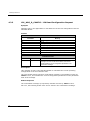
1: Dialogic® DSI SPCI Network Interface Board Capability ............................................................. 8
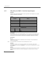
2: Relationship between License Button Codes, Run Modes and Protocol Modules ........................... 13
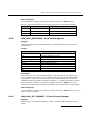
3: Protocol Dimensioning ........................................................................................................ 13
4: Message Summary ............................................................................................................. 20
6. DSI SPCI Board Software Module IDs.................................................................................... 22
7. Message Status Responses .................................................................................................. 22
Figures
Figure 1 Drop and Insert ................................................................................................................. 19
Figure 2 Protocol Configuration Message Sequence Diagram ................................................................ 74
4
Dialogic® DSI SPCI Network Interface Boards Programmer's Manual Issue 7
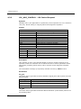
Revision History
Issue
Date
Description
7
04-Apr-12
Re-structured manual. Configuration and installation details moved to DSI Software
Environment Programmer’s Manual.
6
12-Feb-10
Updated to reflect changed support for Windows®. SWITCH_XCON command
documented.
5
20-Mar-09
Clarification to ISUP-S and TUP-S protocol dimensioning.
4
05-Mar-09
Removed CPM8 specific content as product is now EOL.
Updated to Dialogic® branding. Refreshed operating system support and
documented new “bundled” license button set and corresponding run modes.
3
23-May-05
Remove INAP_API module.
Change name of package in Solaris DPK to <dpksol32.Z / dpksol64.Z >.
Add geographic addressing, gctload as a service, watchdog timer, Linux driver
source code release.
Added board Option Switch / Link settings, General Module Identification Message
and Read Board Info Request Message and Set on-board LED's Message.
Add capacity section and support for Windows® XP.
2
06-Jan-03
Branding changed to Intel® NetStructure™. Septel PCI now SPCI4 / SPCI2S and
Septel cP now CPM8. References to NUP protocol removed. INAP_API.LIB added.
1
30-Jul-01
Sections detailing support for Windows® 2000, Linux and Solaris added. Additional
messages to read LIU state, indicate clock events and s7_mgt completion status.
5
1 Introduction
1
Introduction
The range of Dialogic® DSI SPCI Network Interface Boards includes specialized T1/E1
SS7 signaling boards for use in PCI host computer systems. All boards offer a common
interface to the application allowing applications to be easily ported between hardware
architectures. This Programmer’s Manual relates to the low density Dialogic® DSI
SPCI4 Network Interface Boards and Dialogic® DSI SPCI2S Network Interface Boards.
Each low density board contains an embedded signaling processor capable of handling
up to 4 SS7 signaling links and runs software which is downloaded onto the board at
run time.
The boards provide a suitable hardware platform for running the Dialogic® DSI protocol
for realizing Signaling System Number 7 signaling nodes. The boards can be used
under any of the following operating systems: Windows® XP, Windows® Vista, Windows
Server® 2008, Windows Server® 2008 R2 and Windows® 7, Linux and Solaris. This
document is the Dialogic® DSI SPCI Network Interface Boards Programmer’s Manual
and it is targeted at system developers who choose to integrate the boards in a host
computer and to develop applications that make use of the underlying SS7 protocol
stack. The Programmer's Manual includes information on software installation, system
configuration, protocol configuration, and operation of the board and SS7 software
stack.
The Programmer's Manual should be used in conjunction with the appropriate
Installation Guide and Regulatory Notice for the board, the Dialogic® Distributed
Signaling Interface Components – Software Environment Programmer's Manual and
the Programmer’s Manuals for the individual protocol modules as detailed in section
1.1.
High Density board ranges SS7HD and SS7MD are not covered by this manual, and
users should refer instead to the relevant documentation package.
1.1
Related Information
Refer to the following for related information:
Dialogic® DSI SPCI Network Interface Boards Installation Guide
Dialogic® DSI SPCI Regulatory Notices
Dialogic® Distributed Signaling Interface Components – Software Environment
Programmer's Manual
Dialogic® SS7 Protocols MTP2 Programmer’s Manual
Dialogic® SS7 Protocols MTP3 Programmer’s Manual
Dialogic® SS7 Protocols ISUP Programmer's Manual
Dialogic® SS7 Protocols TUP Programmer’s Manual
Dialogic® DSI Protocol Stacks - Host Licensing User Guide
Dialogic® DSI SS7HD Network Interface Boards Programmer’s Manual
Dialogic® DSI Signaling Servers Manual
Dialogic® DSI Protocol Stacks SNMP User Manual
6
Dialogic® DSI SPCI Network Interface Boards Programmer's Manual Issue 7
Current software and documentation supporting Dialogic® DSI products is available at
http://www.dialogic.com/support/helpweb/signaling
Product data sheets are available at
http://www.dialogic.com/support/helpweb/signaling
For more information on Dialogic® DSI SS7 products and solutions, visit
http://www.dialogic.com/support/helpweb/signaling
7
2 Specification
2
Specification
This section provides information about:
Product Identification
Dialogic® DSI SPCI Network Interface Board
License Buttons
SNMP Support
Regulatory and Geographic Considerations
2.1
Product Identification
The product designations are as follows:
Dialogic® DSI SPCI4 Network Interface Boards – Four T1/E1 interfaces
Dialogic® DSI SPCI2S Network Interface Boards – Two T1/E1 interfaces and
two serial interfaces
Throughout this manual the term "SPCI" is used to refer (individually and/or
collectively, depending on context) to either or both such type of boards.
2.2
Dialogic® DSI SPCI Network Interface Board
The DSI SPCI board is a standard height, full length PCI form factor. Features of the
DSI SPCI board are described in the following topics:
Capability
Host Interface
Physical Interfaces
Protocol Resource Support
Visual Indicators
Power Requirements
Environmental Specification
Safety, EMC and Telecommunications Specifications
Reliability
2.2.1
Capability
Table 1: Dialogic® DSI SPCI Network Interface Board Capability
8
Number of:
SPCI4
SPCI2S
T1/E1 links
4
2
V.11 / V.35 synchronous serial interfaces
0
2
H.100 Computer Telephony bus (CT bus)
1
1
SS7 links
4
4
Dialogic® DSI SPCI Network Interface Boards Programmer's Manual Issue 7
2.2.2
Host Interface
The DSI SPCI board is a 32-bit PCI board, but can also be installed in 64-bit PCI slots.
The board is keyed as universal and can be installed in either 5 V or 3.3 V signaling
environment slots.
2.2.3
Physical Interfaces
The DSI SPCI board supports the following physical interfaces:
•
DSI SPCI4 - Four T1/E1 digital trunk interfaces. See Section 2.3.1, “Run Modes”
below for more detail.
DSI SPCI2S – Two T1/E1 digital trunk interfaces.
2.2.3.1
T1/E1 Digital Trunk Interface Properties
The properties of the T1/E1 digital trunk interfaces are described as follows:
•
Standard
—Each interface is software configurable as either T1 or E1
•
Pulse mask
— T1: AT&T TR62411
— E1: ITU-T G.703
•
Data rate
— T1: 1544 kbits/s ± 50 ppm
— E1: 2048 kbits/s ± 50 ppm
•
Frame format
— T1: D4 and ESF
— E1: E1 and E1-CRC4
•
Line codes
— T1: B8ZS and AMI
— E1: HDB3 and AMI
•
Connector type
— RJ-48C
2.2.3.2
SS7 Serial Interface Ports (DSI SPCI2S)
Connector
— 26 pin High density D-type female shared between both ports
Electrical
— V.11 (V.35 compatible)
Signals
— Tx Clock, Rx Clock, Tx Data, Rx Data
9
2 Specification
Data Rate
— 48kbit/s, 56 kbit/s, 64 kbit/s or external.
2.2.3.3
H.100 CT Bus
An H.100 CT Bus interface is provided to allow connection to other H.100 compatible
boards. The H.100 CT Bus supports 4096 channels (or timeslots) and the associated
clock and framing signals. This board is capable of generating the CT Bus clocks, or
can act as a slave. CT Bus channels may be used individually, or grouped to provide a
higher bandwidth data path.
The signals are carried between boards in a host computer using an H.100 CT Bus
ribbon cable.
Bus type
— H.100 CT Bus
Clock rate
— 8192 kHz
Connector
— Edge connector
Clocking
— Master or Slave
2.2.4
Protocol Resource Support
When used in a signaling node, the DSI SPCI board supports the Message Transfer Part
(MTP) running on the board and optionally other protocols including MTP3, ISUP and
TUP. Board based protocols are enabled by a license button.
MTP3, ISUP, TUP, SCCP, TCAP, MAP, INAP and IS41 can also be run on the host. The
protocols are enabled by software licenses. See Section 2.3, “License Buttons” on page
12.
2.2.5
Visual Indicators
The DSI SPCI board includes the following visual indicators:
User LED’s : Three general purpose red LEDs, labeled A, B and C, are available to the
user application.
2.2.6
Power Requirements
Power requirements are described as follows:
• +5 VDC ± 5% power
2.0 A max., 1.5 A typ.
• Power dissipation
10.5 W max.
10
Dialogic® DSI SPCI Network Interface Boards Programmer's Manual Issue 7
2.2.7
Physical Specification
Form factor
standard height, full length PCI board
Dimensions
Board
Length
341 mm (13.425 inches)
Height
106 mm (4.17 inches)
Packaged
Length
406.4 mm (16 inches)
Width
219 mm (8.625 inches)
Height
44.5 mm (1.75 inches)
Weight
Board
DSI SPCI2S
211 g
DSI SPCI4
180 g
Packaged board
2.2.8
DSI SPCI2S
553 g
DSI SPCI4
522 g
Environmental Specification
Environmental specification is described as follows:
• Operating temperature range
+0°C to +55°C
• Storage temperature range
-40°C to +70°C
• Humidity
0 to 95% non-condensing
• Altitude
0 to 3,500 ft
2.2.9
Safety, EMC and Telecommunications Specifications
Safety, EMC and telecommunications specification information is provided by the
following:
• Dialogic® DSI SPCI4 Network Interface Boards and Dialogic® DSI SPCI2S Network
Interface Boards Regulatory Notices
11
2 Specification
Supplied with each product and provides a list of the specifications to which the DSI
SPCI board conforms.
• International Declaration of Conformity
See http://www.dialogic.com/declarations
• Country-Specific Approvals
See the Global Product Approvals list at http://www.dialogic.com/declarations
Alternatively, contact your Dialogic technical sales representative for more information.
2.2.10
Reliability
Product reliability is described by:
• MTBF Predication
204,000 hours per Bellcore Method @40ºC
• Warranty
See Dialogic® Telecom Products Warranty Information at
http://www.dialogic.com/warranties
2.3
License Buttons
The ss7.dc3 code file supports different protocol module combinations that are enabled
by fitting the correct license button to the board. Each license button is marked with a
two letter code that is used for identification.
2.3.1
Run Modes
The run_mode parameter in either the SS7_BOARD command or the Board Reset
Request message determines the protocol modules that are started by the code file at
run time. The following table shows the relationship between the license buttons and
the supported run modes.
12
Dialogic® DSI SPCI Network Interface Boards Programmer's Manual Issue 7
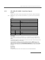
2.3.2
MON
TUP-L
TUP
TUP-S
ISUP-L
ISUP
ISUP-S
MTP3
Run Modes supported
MTP2
Maximum Number
of SS7 Links
Description
Button Code
Item Market Name
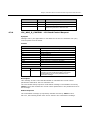
Table 2: Relationship between License Button Codes, Run Modes and Protocol
Modules
√
MM
SS7SBPCIMONQ
Monitoring
4
M3
SS7SBPCIMTPQ
MTP
4
√
√
T1
SS7SBPCIISTUPSQ
ISUP, TUP (Small)
2
√
√
T2
SS7SBPCIISTUPQ
ISUP, TUP (Regular)
4
√
√
T4
SS7SBPCIISTUPLQ
ISUP, TUP (Large)
4
√
√
√
√
√
√
√
√
√
√
√
√
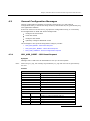
Capacity
The figures in the table below indicate the capacity for modules running on the DSI
SPCI Boards.
Table 3: Protocol Dimensioning
Capacity
Maximum
Number of Link
Sets
Maximum
Number of
Routes
Maximum
Number of
Circuit Groups
Maximum
Numbers of
Circuits
Run Mode
2.4
MTP3
4
64
ISUP-S
2
64
44
1024
TUP-S
2
64
44
1024
ISUP
4
64
64
2048
TUP
4
64
64
2048
ISUP-L
4
64
128
4096
TUP-L
4
64
128
4096
SNMP Support
The Dialogic® Distributed Structured Management Information (DSMI) Simple Network
Management Protocol (SNMP) Agent provides SNMP monitoring functionality for the
Dialogic® DSI SS7 Development Package.
Dialogic® DSMI SNMP software supports SNMP V1, V2 and V3 reporting the state and
events for Dialogic® DSI SPCI Boards and Dialogic® DSI Protocol Stacks through use of
SNMP traps as well as queries from a SNMP manager.
13
2 Specification
The Dialogic® DSMI MIBs are distributed within the Dialogic® DSI SS7 Development
Package in the /opt/DSI sub-directory as a compressed ZIP file: dsi-mibs.zip.
For details of the DSMI SNMP MIBs supported, events, SNMP traps and configuration
refer to the Dialogic® DSI Protocol Stacks SNMP User Manual.
2.5
Regulatory and Geographic Considerations
Certain functions of the Dialogic® DSI SPCI Network Interface Boards, although
implemented in hardware, have selectable options that are configured by the software.
A user or integrator must consider the requirements of the application when choosing
these settings, but must also consider any local regulatory requirements for the
intended deployment location to provide a compliant overall system. As an aid to this
process, the table below details some of the areas where the correct selection of
configuration options may be required.
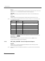
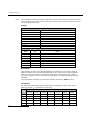
Configuration Area
T1/E1 Ports
Configuration Options
Interface type
liu_type parameter in LIU_CONFIG command
Pulse shape
liu_type parameter in LIU_CONFIG command
Line code
line_code parameter in LIU_CONFIG command
Frame format
frame_format parameter in LIU_CONFIG command
CRC/E-bit operation
CRC_mode parameter in LIU_CONFIG command
Clock priorities
flags parameter in SS7_BOARD command and
options parameter in LIU_CONFIG command
Master/Slave configuration
flags parameter in SS7_BOARD command
Bus termination
flags parameter in SS7_BOARD command
Link termination or monitoring
mode
MTP_LINK or MONITOR_LINK commands
CT Bus
Links
Note:
14
For details on these configuration commands please refer to Dialogic® Distributed Signaling
Interface Components – Software Environment Programmer's Manual.
Dialogic® DSI SPCI Network Interface Boards Programmer's Manual Issue 7
3
SPCI Board Configuration and Operation
Before attempting software configuration, you should gain an understanding of the
flexibility of the protocol stack, the run-time options that exist and the mechanisms
that are used to select specific features. This section gives an overview of these
options. You should also read the Dialogic® Distributed Signaling Interface Components
– Software Environment Programmer's Manual that describes the basic principles of
modules and message passing.
This section provides information about:
System configuration using SPCI Boards
Board Code File
Using the CT bus
3.1
System configuration using SPCI Boards
Some SS7 protocol modules can be run on either the host machine or on DSI SPCI
boards. The following table shows the possible options for each protocol:
Protocol
Option
ISUP, TUP
Host or board
MTP3
Host or board
MTP2
Board only.
Host protocol software is available for Linux, Solaris SPARC, Solaris x86 and Windows®
operating systems. For more information or to purchase, contact an authorized
distributor or your account manager.
The Dialogic® DSI SPCI Network Interface Board may be configured for most
applications using the s7_mgt utility. The s7_mgt utility is the primary tool for
configuring a DSI software stack. It is a single-shot configuration utility that takes
configuration commands from a text file (config.txt).
Details on how to configure a system using s7_mgt are provided in the Dialogic®
Distributed Signaling Interface Components – Software Environment Programmer's
Manual.
As an alternative to using s7_mgt, users can build their own configuration utilities
using messaged-based configuration. In this case users should refer to the definitions
of individual messages in Section 4, Message Reference on page 20.
The Code File contains the operating firmware for the board which is downloaded to
the board at run-time by the ssds binary. The code file should be specified in the
SS7BOARD command in the config.txt file.
3.2
Board Code File
The DSI Network Interface Boards Code Files contain the operating software for the
DSI Network Interface Boards. The appropriate code file must be downloaded by the
host, to the board, at run-time.
The following code files available for the DSI SPCI board:
15
3 SPCI Board Configuration and Operation
The ss7.dc3 code file which should be used for DSI SPCI boards running SS7
protocols.
The mon.dc3 code file which should be used for DSI SPCI boards running
monitoring applications.
Note:
The *.dc3 code file are distributed as part of the Dialogic® DSI Development Package.
The code file requires a license button to be fitted to the board which enables the
software to run on the board, details are given in Section 2.3 License Buttons on page
12.
3.3
Using the CT bus
The DSI SPCI2S and DSI SPCI4 boards support two or four T1/E1 Line Interface Units
and a CT bus interface (H.100) respectively. The on-board signaling processor handles
the SS7 signaling timeslots whilst the remaining circuits (voice or data bearer circuits)
are passed to the CT bus for distribution to other boards.
All communication between the application and the board is message-based. Initial
configuration is usually handled by the configuration utility s7_mgt, which takes
commands from the text file (config.txt) and generates all the necessary
configuration messages for the board. Subsequent operation is entirely message
driven, messages being passed in both directions between the board and the
application.
One of the roles of the application is to control the dynamic switching between the CT
bus and the T1/E1 line interfaces. This section provides details of how to interface with
the CT bus, including the initial (static) configuration and the subsequent (dynamic)
switching.
The operation of the CT bus switching interface is described in terms of the SCbus
switching model using the messages MVD_SC_DRIVE_LIU, MVD_MSG_SC_LISTEN
and MVD_MSG_SC_FIXDATA and config.txt commands LIU_SC_DRIVE and
SCBUS_LISTEN.
3.3.1
Switching Model
The basic switching model assumes that at system initialization all incoming T1/E1
timeslots and all resource board output timeslots are connected up to channels on the
CT bus and that these connections are never changed. This has the advantage that
once the on-board CT bus drivers have been set up they are never changed so the
chances of inadvertently causing CT bus conflict is minimized. It also means that the
user can predict the exact CT bus channels where any input timeslot can be located
and this in turn can assist with fault diagnosis and general system test.
It is also possible to generate fixed patterns on any T1/E1 output timeslots to provide
the correct idle pattern for presentation to the network on all circuits where there is no
active call.
Having completed the system initialization, all drives to the CT bus are set up. Then,
on a dynamic (call by call) basis, the connectivity must be modified when a new call
arrives and when it finishes.
When a new call arrives, the application, in general, needs to initiate two listen
commands. One command causes the resource to listen to the appropriate CT bus
channel to hear the incoming voice path and the other causes the T1/E1 interface to
listen to the output from the resource board to generate the outgoing voice path.
16
Dialogic® DSI SPCI Network Interface Boards Programmer's Manual Issue 7
When a call clears, the application needs to initiate generation of the fixed idle pattern
towards the network operation (and may wish to connect an idle pattern to the
resource board).
3.3.2
Static Initialization
Static initialization is handled by the s7_mgt utility. For each T1/E1 line interface unit,
user must include an LIU_SC_DRIVE command in the config.txt file. The syntax for
this command is detailed in Dialogic® Distributed Signaling Interface Components –
Software Environment Programmer's Manual.
The LIU_SC_DRIVE command has several parameters. board_id and liu_id together
uniquely identify the affected line interface unit. sc_channel is the channel number of
the first channel on the CT bus that is to be used for timeslots from the specified LIU.
ts_mask is a mask identifying which timeslots on the T1/E1 interface are carrying
voice circuits (as opposed to signaling) and therefore need to be connected to the CT
bus. The least significant bit of ts_mask must always be zero when driving from an
T1/E1 interface.
As an example, consider a two board system where the first board has 4 E1 ports and
the second board has 4 T1 ports. We allow the first 512 CT bus channels to be used by
other boards in the system and therefore start at sc_channel 512.
LIU_SC_DRIVE
LIU_SC_DRIVE
LIU_SC_DRIVE
LIU_SC_DRIVE
LIU_SC_DRIVE
LIU_SC_DRIVE
LIU_SC_DRIVE
LIU_SC_DRIVE
3.3.3
0
0
0
0
1
1
1
1
0
1
2
3
0
1
2
3
512
542
572
602
632
655
678
701
0xfffefffe
0xfffefffe
0xfffefffe
0xfffefffe
0x00fffffe
0x00fffffe
0x00fffffe
0x00fffffe
*
*
*
*
*
*
*
*
30
30
30
30
23
23
23
23
E1
E1
E1
E1
T1
T1
T1
T1
voice
voice
voice
voice
voice
voice
voice
voice
ccts
ccts
ccts
ccts
ccts
ccts
ccts
ccts
on
on
on
on
on
on
on
on
ts 1..15 & 17..31
ts 1..15 & 17..31
ts 1..15 & 17..31
ts 1..15 & 17..31
timeslots 1..23
timeslots 1..23
timeslots 1..23
timeslots 1..23
Dynamic Operation
The application controls dynamic changes to CT bus switching by sending the
MVD_MSG_SC_LISTEN message to the board. This message is documented in
Section 4.3.6 MVD_MSG_SC_LISTEN - CT bus Listen Request. It contains the liu_id,
the timeslot number on the T1/E1 interface and the CT bus channel number
(sc_channel) to which the timeslot listens. The message is directed to the correct
board by calling the GCT_set_instance function prior to calling GCT_send.
When a new call arrives, the application needs to instigate two listen commands
(although they do not necessarily both apply to the SS7 board). One connects the
voice circuit in the forward direction and the other connects it in the backward
direction.
When a call terminates, the application must issue a fixed data message to ensure the
network port sees the voice idle pattern.
3.3.4
Example Code - Building and Sending SC_LISTEN
/*
* Example function for building and sending an MVD_MSG_SC_LISTEN
* message to a SPCI2S or SPCI4 signalling board.
*
* The only change that the user needs to make is to fill in the
* OUR_MOD_ID definition below so that is equal to the module_id
* of the application module.
*/
17
3 SPCI Board Configuration and Operation
#define OUR_MOD_ID
#include
#include
#include
#include
#include
#include
(0xef)
"system.h"
"msg.h"
"libc.h"
"sysgct.h"
"pack.h"
"ss7_inc.h"
/*
/*
/*
/*
/*
/*
Definitions of u8, u16 etc */
Definitions of HDR, MSG etc */
Used only for memset prototype */
Prototypes for GCT_xxx */
Prototypes for rpackbytes */
Message & module definitions */
/*
* Macro to generate the value for use in the rsp_req field of the
* message header in order to request a confirmation message:
*/
#define RESPONSE(module)
(((unsigned short) 1) << ((module) & 0x0f))
/*
* Function to drive an SCbus / CT bus timeslot
* onto a timeslot on a PCM port:
*/
int listen_to_scbus(board_id, liu_id, timeslot, sc_channel)
int board_id;
/* board_id (0, 1, 2 ...) */
int liu_id;
/* PCM port id (*/
int timeslot;
/* Timeslot on the PCM port (1 .. 31) */
int sc_channel;
/* SCbus / CT bus channel number */
{
MSG
*m;
u8
*pptr;
/*
* Allocate a message (and fill in type, id, rsp_req & len):
*/
if ((m = getm(MVD_MSG_SC_LISTEN, 0, RESPONSE(OUR_MOD_ID), MVDML_SCLIS)) != 0)
{
pptr = get_param(m);
memset(pptr, 0, m->len);
/*
* Enter the parameters in machine independent format:
*/
rpackbytes(pptr, MVDMO_SCLIS_liu_id, (u32)liu_id, MVDMS_SCLIS_liu_id);
rpackbytes(pptr, MVDMO_SCLIS_timeslot, (u32)timeslot, MVDMS_SCLIS_timeslot);
rpackbytes(pptr, MVDMO_SCLIS_sc_channel, (u32)sc_channel,
MVDMS_SCLIS_sc_channel);
m->hdr.dst = MVD_TASK_ID;
m->hdr.src = OUR_MOD_ID;
/*
* Call GCT_set_instance to route the message to the
* correct board and GCT_send to send the message.
* If GCT_send returns non-zero release the message.
*/
GCT_set_instance(board_id, (HDR *)m);
if (GCT_send(m->hdr.dst, (HDR *)m) != 0)
relm((HDR *)m);
}
return(0);
}
18
Dialogic® DSI SPCI Network Interface Boards Programmer's Manual Issue 7
3.3.5
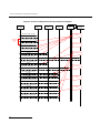
Interconnecting LIUs using STREAM_XCON
Interconnection of two Line Interface Units (LIUs) on the Dialogic® DSI SPCI Interface
Network Board is also supported through the STREAM_XCON command which controls
the cross connect switch on the DSI SPCI Board signaling, enabling the cross
connection of timeslots between any two LIUs within the DSI SPCI Board. This
command simplifies the cross connection enabling a group of timeslots on one LIU to
be directly mapped to the same numbered timeslots on a second LIU on the same DSI
SPCI Board using a single command. A typical usage of the STREAM_XCON command
is shown in Figure 2 which implements Drop and Insert functionality.
Figure 1 Drop and Insert
19
4 Message Reference
4
4.1
Message Reference
Overview
This section describes the individual messages that may be sent to and received from
the Dialogic® DSI SPCI Network Interface Board. Some messages are sent by the
user's application software whilst others are sent by utility programs such as the
s7_mgt protocol configuration utility.
Prior to sending any message to the board, the application should call the
GCT_set_instance( ) library function to select which board the message will be sent
to. After receiving a message from the board, the application should call the
GCT_get_instance( ) library function to determine which board the message came
from. These library functions are described in the Software Environment Programmer's
Manual.
The various messages used are grouped in the following categories:
General Configuration Messages
Hardware Control Messages
Event Indication Messages
Status Request Messages
4.1.1
Message Type Summary
The following table lists, by message type, the messages described in this manual:
Table 4: Message Summary
Message
Type
20
Mnemonic
Description
0x0008
MGT_MSG_EVENT_IND
Error Indication
0x0201
MGT_MSG_SS7_STATE
MTP2 Level 2 State Indication
0x0202
MGT_MSG_SS7_EVENT
MTP2 Q.752 Event Indication
0x0301
MGT_MSG_MTP_EVENT
MTP3 Q.752 Event Indication
0x06a0
SSD_MSG_STATE_IND
Board Status Indication
0x0e01
MVD_MSG_LIU_STATUS
LIU Status Indication
0x0e23
MVD_MSG_CLK_IND
Clock Event Indication
0x0f09
API_MSG_CNF_IND
s7_mgt Completion Status Indication
0x1e37
Confirmation of LIU_MSG_R_CONFIG
0x1e38
Confirmation of LIU_MSG_R_CONTROL
0x1e39
Confirmation of LIU_MSG_R_STATE
0x3312
Confirmation of MTP_MSG_CNF_ROUTE
0x3680
Confirmation of SSD_MSG_RESET
0x3681
Confirmation of SSD_MSG_RST_BOARD
0x3e00
Confirmation of MVD_MSG_RESETSWX
Dialogic® DSI SPCI Network Interface Boards Programmer's Manual Issue 7
Message
Type
Mnemonic
Description
0x3e15
Confirmation of MVD_MSG_SC_FIXDATA
0x3e17
Confirmation of MVD_MSG_SC_LISTEN
0x3e18
Confirmation of MVD_MSG_SC_DRIVE_LIU
0x3e19
Confirmation of
MVD_MSG_SC_MULTI_CONNECT
0x3e1f
Confirmation of MVD_MSG_SC_CONNECT
0x3e20
Confirmation of MVD_MSG_CNFCLOCK
0x3e21
Confirmation of MVD_MSG_CLK_PRI
0x3e34
Confirmation of LIU_MSG_CONFIG
0x3e35
Confirmation of LIU_MSG_CONTROL
0x3f10
Confirmation of MGT_MSG_CONFIG0
0x5e36
LIU_MSG_R_STATS
LIU Read Statistics Request
0x5e37
LIU_MSG_R_CONFIG
LIU Read Configuration Request
0x5e38
LIU_MSG_R_CONTROL
LIU Read Configuration Request
0x5e39
LIU_MSG_R_STATE
LIU State Request
0x6f0d
MGT_MSG_R_BRDINFO
Read Board Info Request Message
0x7680
SSD_MSG_RESET
SSD Reset Request
0x7681
SSD_MSG_RST_BOARD
Board Reset Request
0x7e00
MVD_MSG_RESETSWX
Reset Switch Request
0x7e15
MVD_MSG_SC_FIXDATA
Fixed Data Request
0x7e17
MVD_MSG_SC_LISTEN
SCbus Listen Request
0x7e18
MVD_MSG_SC_DRIVE_LIU
SCbus Initialization Request
0x7e19
MVD_MSG_SC_MULTI_CONNECT
Multiple Connect Request
0x7e1f
MVD_MSG_SC_CONNECT
SCbus Connect Request
0x7e20
MVD_MSG_CNFCLOCK
Configure Clock Request
0x7e21
MVD_MSG_CLOCK_PRI
Configure Clock Priority Request
0x7e34
LIU_MSG_CONFIG
LIU Configuration Request
0x7e35
LIU_MSG_CONTROL
LIU Control Request
0x7f10
MGT_MSG_CONFIG0
Board Configuration Request
21
4 Message Reference
4.1.2
Board-specific Module IDs
Table 5 lists the software modules IDs (by mnemonic and value) used on the DSI SPCI
Board.
Table 5. DSI SPCI Board Software Module IDs
Mnemonic
Value
Description
MGMT_TASK_ID
0x8e
SPCI Board Management Module
MVD_TASK_ID
0x10
SPCI LIU and Switch Management Module
SS7_TASK_ID
0x71
MTP2 Module
MTP_TASK_ID ‡
0x22
Onboard MTP3 Protocol module
ISUP_TASK_ID ‡
0x23
Onboard ISUP Protocol module
TUP_TASK_ID ‡
0x4a
Onboard TUP Protocol module
NOTES:
1. ‡ The availability of these Module IDs depends on the selected board run_mode. See Section 2.3.1,
Run Modes on page 12 for more information.
4.1.3
Message Status Summary
The following table shows the valid responses when a response request (rsp_req) is
requested in a message.
Table 6. Message Status Responses
Value
22
Mnemonic
Description
0x00
SDE_MSG_OK
Success
0x01
SDE_BAD_ID
Inappropriate or invalid id in request message
0x02
SDE_BAD_STATE
Message received in wrong state
0x03
SDE_BAD_SIG
Bad signal received
0x04
SDE_UNEX_SIG
Unexpected signal received
0x05
SDE_BAD_MSG
Unsupported message received
0x06
SDE_BAD_PARAM
Invalid parameters contained in message
0x07
SDE_NO_RESOURCES
Insufficient internal message resources
0x08
SDE_INVALID_NC
Invalid Network Context
0x09
SDE_INVALID_VERSION
Message version is invalid
0x0e
SDE_LICENCE_ERR
Failure due to a licensing restriction
0x0f
SDE_INTERNAL_ERR
Failure due to an internal error
Dialogic® DSI SPCI Network Interface Boards Programmer's Manual Issue 7
4.2
General Configuration Messages
General configuration messages are typically issued by the s7_mgt protocol
configuration utility, in which case they need not, and should not, be generated by any
user application software.
If the user elects not to use the s7_mgt protocol configuration utility, it is necessary
for the application to build and send messages that:
configure the ssd module
reset each board
configure each board
optionally configure additional routes
The messages in the general configuration category include:
4.2.1
SSD_MSG_RESET - SSD Reset Request
SSD_MSG_RST_BOARD - Board Reset Request
MGT_MSG_CONFIG0 - Board Configuration Request
SSD_MSG_RESET - SSD Reset Request
Synopsis
Message sent to SSD once at initialization to set up run-time options.
Note:
When using s7_mgt, this message is generated by s7_mgt and must not be generated by
the user.
Format
MESSAGE HEADER
Field Name
Meaning
type
SSD_MSG_RESET (0x7680)
id
0
src
Sending module's module_id
dst
SSD_TASK_ID (0x20)
rsp_req
used to request a confirmation
hclass
0
status
Status Response (if confirmation requested)
err_info
0
len
24
PARAMETER AREA
Offset
Size
Name
0
1
module_id - must be set to SSD_TASK_ID
1
2
reserved – set to zero
3
1
mgmt_id
4
18
reserved – set to zero
22
2
num_boards
23
4 Message Reference
Description
This message is used during initialization by the application to reset the ssd module
and set up its run-time parameters.
Parameters
mgmt_id
The module_id of the management module, to which ssd sends board status
indications.
num_boards
The maximum number of boards that ssd is required to manage. This must not exceed
16.
Status Response
The confirmation message (if requested) indicates success by status of zero.
On error, the following value can be found in the status message confirmation.
Value
2
24
Mnemonic
Description
SSD_BAD_PARAM
The SSD Reset Request message was incorrectly formatted.
Dialogic® DSI SPCI Network Interface Boards Programmer's Manual Issue 7
4.2.2
SSD_MSG_RST_BOARD - Board Reset Request
Synopsis
Message sent to SSD to cause a single board to be reset and a code file downloaded.
Note:
When using s7_mgt, this message is generated by s7_mgt and must not be generated by
the user.
Format
MESSAGE HEADER
Field Name
Meaning
type
SSD_MSG_RST_BOARD (0x7681)
id
board_id
src
Sending module's module_id
dst
SSD_TASK_ID (0x20)
rsp_req
used to request a confirmation
hclass
0
status
Status Response (if confirmation requested)
err_info
0
len
26
PARAMETER AREA
Offset
Size
Name
0
2
board_type
2
4
phy_id
6
18
code_file
24
2
run_mode
Description
This message is used during initialization (or re-configuration) by the application to
reset a board and download the code file that contains the operating software for the
board.
The download operation is supervised by the device driver that reads the binary format
code file and transfers it to the board.
The confirmation message (if requested) indicates success by status of zero. This
implies that the reset operation has commenced but does not imply completion. The
application must then wait until a Board Status Indication is received. This indicates
either successful completion of the reset and download operation or failure during the
procedure.
Parameters
board_type
The type of board to be reset. This must be set to 2 for DSI SPCI Boards.
25
4 Message Reference
phy_id
The physical ID for the DSI SPCI Board. This field must be set to the same value as the
board_id. (i.e., 0 … one less than the number of boards supported).
code_file
Null terminated string giving the filename of the code file to be downloaded to the
board.
run_mode
Number taken from the following table to indicate which protocols are to be run.
Note:
It is only possible to activate protocols that have been licensed to run on the board by use
of a suitable license button.
Run Mode
Value
Run Mode
Mnemonic
Protocols selected to run on the board
1
DTI
Digital Trunk Interface only, no protocol software. This
mode does NOT require the use of a software license
button.
2
MTP2
MTP2 protocol only.
3
MTP
MTP3 plus MTP2 protocols.
25
ISUP-S
ISUP, small version, plus all MTP.
4
ISUP
ISUP, regular version, plus all MTP.
5
ISUP-L
ISUP, large version, plus all MTP.
26
TUP-S
TUP, small version, plus all MTP.
6
TUP
TUP, regular version, plus all MTP.
7
TUP-L
TUP, large version, plus all MTP.
See section 2.3.2 Capacity for details of the capacity for modules running on the DSI
SPCI Boards.
Status Response
The confirmation message (if requested) indicates success by status of zero.
No status values indicating errors are defined.
4.2.3
MGT_MSG_CONFIG0 - Board Configuration Request
Synopsis
Message sent to a board immediately after starting the code running to provide
protocol configuration parameters.
Note:
26
When using s7_mgt, this message is generated by s7_mgt and must not be generated by
the user.
Dialogic® DSI SPCI Network Interface Boards Programmer's Manual Issue 7
Format
MESSAGE HEADER
Field Name
Meaning
type
MGT_MSG_CONFIG0 (0x7F10)
id
0
src
Sending module's module_id
dst
MGMT_TASK_ID (0x8e)
rsp_req
used to request a confirmation
hclass
0
status
Status Response (if confirmation requested)
err_info
0
len
68
PARAMETER AREA
Offset
Size
Name
0
2
config_type (Must be set to 2)
2
2
flags
4
2
l1_flags
6
2
l2_flags
8
2
max_sif_len
10
2
l3_flags
12
4
pc
16
2
ssf
18
2
up_enable
20
2
link0_flags
22
2
link0_slc
24
4
link0_adj_pc
28
2
link0_stream
30
2
link0_timeslot
32
2
link1_flags
34
36
40
42
44
46
48
52
54
56
58
60
64
66
2
4
2
2
2
2
4
2
2
2
2
4
2
2
link1_slc
link1_adj_pc
link1_stream
link1_timeslot
link2_flags
link2_slc
link2_adj_pc
link2_stream
link2_timeslot
link3_flags
link3_slc
link3_adj_pc
link3_stream
link3_timeslot
27
4 Message Reference
Description
This message must be the first message sent to the DSI SPCI Board once the SS7
software is running. It is used to configure all modules on the board for operation. The
message contains signaling point codes for this signaling point and the adjacent
signaling point(s), flags to permit various level 1, level 2, and level 3 run-time options
to be selected and the physical link parameters.
Once the DSI SPCI Board has been configured, you must reset it before configuring it
again.
The confirmation message (if requested) indicates success by status of zero. To
ensure configuration is complete before subsequent messages are issued to the board,
the user should always request a confirmation message and check the status for
success.
If the board is not licensed to run the requested software configuration, status value of
0xfe is returned.
Parameters
flags - Global flags
Bit 0 is set to 1 to indicate that the user does not wish to use signaling software. This
allows operation of the board without a software license button providing the board is
used only for T1/E1 interface and switching purposes. If signaling software is required,
then this bit must be set to zero.
Bit 9 is set to 1 to disable automatic MTP route configuration, in which case the user
must send individual MTP Route Configuration messages for each destination. When
set to zero, the board automatically configures an MTP route to each adjacent signaling
point using the link set directly connected to the signaling point.
Bit 12 is set to 1 to cause all signaling links to be automatically activated. Usually, this
bit is set to zero and the user sends individual MTP Link Activation requests to activate
each link.
Bit 15 is set to 1 for diagnostic purposes to cause the results of internal board
configuration to be passed to the host. When set, all confirmation messages generated
internally on the board during the configuration sequence are sent to the module_id
0xdf on the host.
All other bits are reserved for future use and must be set to zero.
l1_flags - level 1 flags
Bit 0 controls the reference source used for on-board clocks when acting as CT bus
Primary Master. If set to 1, the clock is recovered from one of the line interfaces. If set
to zero, the on-board clock oscillator is used.
Bit 6 and 7 together select the initial CT bus clocking mode as shown in the following
table. The clocking mode can be modified subsequently and dynamically using the
MVD_MSG_CNFCLOCK message.
Bit 7
0
28
Bit 6
0
CT bus clocking mode
The CT bus interface is disabled - The board is electrically
isolated from the other boards using the CT bus. The CT bus
connection commands may still be used, but the connections made
are only visible to this board. The on-board clocks are synchronized
to the source selected by bit 0 of this flags parameter.
Dialogic® DSI SPCI Network Interface Boards Programmer's Manual Issue 7
0
1
Primary Master, A Channel - The board drives CT bus clock set A
using the clock source selected by bit 0 of this flags parameter.
1
0
Secondary Master, B Channel - The board is configured to drive
clock set B in Secondary Master mode. The on-board clocks are
synchronized to the CT bus clock set A. It will automatically switch
to become Primary Master if the board driving clock set A fails.
1
1
Slave, initially A Channel – The board uses the CT bus clocks,
which must be generated by another board on the CT bus. Initially
the board recovers from clock set A, though will switch over
automatically to recover from clock set B if set A fails.
Bit 13 is set to 1 to cause the board to drive the CT_NETREF1 clocks on the CT bus.
The highest priority in-sync line interface is used as a clock source. If this bit is set to
zero then CT_NETREF1 clock is not driven.
All other bits are reserved and must be set to zero.
l2_flags - level 2 flags
Bit 1 is set to 1 for ANSI operation or zero for ITU-T operation.
Bit 3 is set to 1 for ANSI operation or zero for ITU-T operation.
Bit 5 is set to 1 to cause Link Status Signal Units (LSSU) to have a two octet status
field. Usually this bit is set to zero, and LSSUs have a single octet status field.
All other bits are reserved for future use and must be set to zero.
max_sif_len - maximum Signaling Information Field length
The maximum Signaling Information Field length in octets that is permitted over the
signaling link. Usually set to 272 although it may be set to 62 for inter-working with
switches that do not support 272 octet messages.
l3_flags - level 3 flags
Bit 0 is set to 1 to disable the level 3 discrimination function (allowing the signaling
point to receive all messages irrespective of the destination point code contained in the
message) or zero to allow the discrimination function to function normally.
Bit 1 is set to 1 to disable sub-service field (SSF) discrimination. If this bit is set to
zero, received MSUs whose ssf values do not match the configured ssf value are
discarded.
Bit 8 is set to 1 to select ANSI operation or zero for ITU-T operation.
Bit 9 is set to 1 to select ANSI style 24 bit point codes in the MTP routing label or zero
to select ITU-T style 14 bit point codes. This bit must be set to 1 if ANSI operation is
selected.
Bit 10 is set to 1 for ANSI operation or zero for ITU-T operation.
Bit 11 is set to 1 for ANSI operation or zero for ITU-T operation.
All other bits are reserved for future use and must be set to zero.
Note:
For ANSI operation bits 8, 9, 10, and 11 must all be set to 1.
pc - point code
The pure binary representation of this signaling point code. Must be in the range 0 to
16383 for 14 bit point code operation, or 0 to 16777215 for 24 bit point code
operation.
29
4 Message Reference
ssf - sub-service field
The value used in the sub-service field of all messages generated by level 3. Must be in
the range 0 to 15. For ANSI operation, the 2 least significant bits must be set to 1.
up_enable - User Part Enable
A 16 bit mask used to enable or disable reception of messages on a per user part
basis. If bit N is set to 1, then messages for user part N are received by the signaling
point.
For example, to enable the TUP User Part (Service indicator = 4) set the up_enable
field to 0x0010, For ISUP (Service Indicator = 5), set the up_enable field to 0x0020.
To use both TUP and ISUP, set up_enable to 0x0030.
linkn_flags - Per link flags
Bit 0 is set to 1 to force the use of the emergency proving period during link
alignment. This bit is usually set to zero and uses the appropriate proving period
according to Q.703.
Bit 1 is set to 1 to cause a signaling link test (in accordance with ITU-T Q.707) to be
carried out before a link is put into service, or zero if a test is not required. This bit is
usually set to 1.
Bit 2 is set to 1 to cause a signaling link test (in accordance with ITU-T Q.707) to be
carried out every 30 seconds. This bit is usually set to 1, but is ignored if Bit 1 is set to
zero.
Bit 8 is used to select the MTP2 error correction mode. It is set to 1 to select PCR
(Preventive Cyclic Retransmission) operation, or zero for the Basic Method of Error
Correction.
Bits 10 and 11 are used to select the data rate for the link as detailed below.
Bit 11
Note:
Bit 10
Data Rate
0
0
64kbps
1
1
56kbps
0
1
48kbps
When using a serial port, 56 kbps and 48 kbps operation is only supported when the clock is
applied externally.
Bit 12 when set MTP2 links are configured individually via SS7_MSG_CONFIG.
Bit 13 is only used when the link has been configured to run over a serial port (i.e., bit
14 is set). If set to 1, an external clock is used (Receive clock). If set to zero, an
internal clock (Transmit clock) is used. If the link has not been configured to run over a
serial port, this bit must be set to zero.
Bit 14 is set to 1 to use a serial port, rather than a PCM timeslot for this link. In this
mode the stream and timeslot parameters for this link are ignored (and must be set to
zero). If this bit is set to zero, the link uses the specified stream and timeslot. The
serial port used by the signaling processors for each link is fixed, according to the
following table:
30
Dialogic® DSI SPCI Network Interface Boards Programmer's Manual Issue 7
Link
Serial Port
0
B
1
A
2
Cannot be used for a serial port.
3
Cannot be used for a serial port.
Bit 15 is set to 1 to disable the link, or zero to enable the link.
All other bits are reserved for future use and must be set to zero.
linkn_slc - Signaling link code
The signaling link code for the link, which must be in the range 0 to 15. The signaling
link code must be agreed with the administration at the other end of the link and must
be unique within a link set. Usually, the first link in a link set is assigned the value 0,
the next 1, and so on.
linkn_adj_pc - Adjacent point code
The point code of the signaling point at the remote end of the link. Must be in the
range 0 to 16383 for 14 bit point code operation or 0 to 16777215 for 24 bit point code
operation.
Note:
All links in a link set must have the same adjacent point code.
linkn_stream - Signaling stream
When linkn_timeslot is set to a non-zero value, the linkn_stream is the logical identity
of the T1/E1 line interface (liu_id - in the range 0 to one less than the number of LIUs
fitted) containing the signaling link.
Note:
For the DSI SPCI2S, stream identifiers for the PCM interfaces are implemented on streams 2
and 3.
linkn_timeslot - Signaling timeslot
The timeslot used for signaling. For an E1 interface, the valid range is
1 ... 31. For a T1 interface, the valid range is 1 ... 24. Alternatively, the timeslot may
be set to zero, and the switch path set up manually using the switch control messages.
Status Response
The confirmation message (if requested) indicates success by status of zero.
On error, the following status value can be found in the confirmation message.
Value
Description
0xfe
The board is not licensed to run the requested software
configuration
0xff
The Board Configuration Request has failed.
31
4 Message Reference
4.3
Hardware Control Messages
Hardware control messages are used to control various hardware devices on the board
including the T1/E1 Line Interface Units (LIUs), the digital cross connect switches and
the clocking mode for the board.
In a static configuration, all these hardware blocks can be set up using the s7_mgt
protocol configuration utility along with the appropriate commands in the config.txt
protocol configuration file.
If dynamic control of the hardware is required (or the user has elected not to use
s7_mgt), the user application must build and send at least some of the hardware
control messages.
The messages in the hardware control category include:
4.3.1
LIU_MSG_CONFIG - LIU Configuration Request
LIU_MSG_CONTROL - LIU Control Request
LIU_MSG_R_CONFIG - LIU Read Configuration Request
LIU_MSG_R_CONTROL - LIU Read Control Request
MVD_MSG_SC_DRIVE_LIU - LIU CT bus Initialization Request
MVD_MSG_SC_LISTEN - CT bus Listen Request
MVD_MSG_SC_FIXDATA - Fixed Data Output Request
MVD_MSG_RESETSWX - Reset Switch Request
MVD_MSG_SC_CONNECT - CT bus Connect Request
MVD_MSG_SC_MULTI_CONNECT - Multiple Connect Request
MVD_MSG_CNFCLOCK - Configure Clock Request
MVD_MSG_CLOCK_PRI - Configure Clock Priority Request
LIU_MSG_CONFIG - LIU Configuration Request
Synopsis
Message sent by the application to establish the operating mode for a Line Interface
Unit (LIU).
Note:
32
When using s7_mgt, this message is generated by s7_mgt as a result of the LIU_CONFIG
command. It therefore does not need be generated by the user.
Dialogic® DSI SPCI Network Interface Boards Programmer's Manual Issue 7
Format
MESSAGE HEADER
Field Name
Meaning
type
LIU_MSG_CONFIG (0x7e34)
id
liu_id
src
Sending Module ID
dst
MVD_TASK_ID (0x10)
rsp_req
used to request a confirmation
hclass
0
status
Status Response (if confirmation requested)0
err_info
0
len
40
PARAMETER AREA
Offset
Size
Name
0
1
liu_type
1
1
line_code
2
1
frame_format
3
1
crc_mode
4
1
build_out
5
1
faw
6
1
nfaw
7
4
Reserved for future use, must be set to zero.
11
1
ais_gen
12
1
rai_gen
13
1
Reserved for future use, must be set to zero.
14
4
clear_mask
18
22
Reserved for future use, must be set to zero
Description
This message is sent to the DSI SPCI Board to configure the operating mode a line
interface unit. All configuration parameters must be supplied in the message (it is not
possible to modify individual operating parameters in isolation). On receipt of the
message the board first verifies that the fitted hardware options support the requested
operating mode and then initializes (or re-initializes) the line interface unit.
The confirmation message (if requested) indicates success by status of zero.
Parameters
A description of the permitted parameter values are given below. When the DSI SPCI
Board is initially configured all the line interfaces are initialized to a disabled condition.
liu_type
The physical type of interface according to the following table. The preferred method
for configuring an E1 interface is to select liu_type=5.
33
4 Message Reference
Note:
liu_type
Description
1
Disabled (used to deactivate a LIU). In this mode the LIU does not produce
an output signal.
3
E1 120ohm balanced interface.
4
T1
5
E1 120ohm balanced interface.
This must be selected by the user to be appropriate for the actual hardware fitted otherwise
an error status is returned.
line_code
The line coding technique taken from the following table:
line_code
Description
1
HDB3 (E1 only).
2
AMI with no Zero Code Suppression.
3
AMI with Zero Code Suppression (The appropriate bit in the clear_mask
parameter may be set to disable Zero Code Suppression for individual
timeslots if required.) (T1 only).
4
B8ZS (T1 only).
frame_format
The frame format taken from the following table:
frame_format
Description
1
E1 double frame (E1 only).
2
E1 CRC4 multiframe (E1 only).
4
D3/D4 (Yellow alarm = bit 2 in each channel) (T1 only).
7
ESF (Yellow alarm in data link channel) (T1 only).
crc_mode
The CRC mode taken from the following table:
crc_mode
Description
1
CRC generation disabled.
2
CRC4 enabled (frame_format must be set to 2).
3
CRC4 compatibility mode (frame_format must be set to 2).
4
CRC6 enabled (frame_format must be set to 7).
build_out
Configurable line build out is not supported by the board, so the following fixed values
must be used.
build_out
34
Description
0
Setting for E1 devices.
1
Setting for T1 devices.
Dialogic® DSI SPCI Network Interface Boards Programmer's Manual Issue 7
faw
The 8 bit value to be used for any E1 frame alignment word bit positions that are not
modified by other options. This allows the spare bit designated "For International Use"
to be set by the user when CRC4 mode is disabled. Valid values are 0x9b or 0x1b.
When using T1, this parameter must be set to zero. [E1 default = 0x9b].
nfaw
The 8 bit value to be used for any E1 non-frame alignment word bit positions that are
not modified by other options. Normally, this parameter is set to 0x9f for E1 operation
and set to zero for T1.
ais_gen
The (initial) mode used to generate the Alarm Indication Signal (Blue Alarm) taken
from the following table. The user may subsequently modify the setting of the outgoing
signal using the LIU_MSG_CONTROL message.
ais_gen
Description
1
Disabled - do not generate AIS / Blue alarm.
2
Enabled - generate AIS / Blue alarm.
rai_gen
The (initial) mode used to generate the Remote Alarm Indication (Yellow Alarm) taken
from the following table. The user may subsequently modify the setting of the outgoing
RAI alarm using the LIU_MSG_CONTROL message.
rai_gen
Description
1
Disabled - do not generate RAI / Yellow alarm.
2
Forced active - generate RAI / Yellow alarm.
3
Automatic generation of RAI / Yellow alarm upon loss of
synchronization.
clear_mask
For use with T1 interfaces and line_code mode 3 (AMI with Zero Code Suppression) to
disable zero code suppression on selected channels. This parameter is a 32 bit mask.
Zero code suppression may be disabled for the signaling channel timeslot by setting
the appropriate bit in the mask. The least significant bit corresponds to timeslot 0 and
the most significant bit to timeslot 31. Bits are set to 1 to disable zero code
suppression.
Status Response
The confirmation message (if requested) indicates success by status of zero.
On error, the following status values can be found in the confirmation message.
Value
Mnemonic
Description
0x01
None
Invalid framer ID.
0x02
None
Invalid message length.
35
4 Message Reference
4.3.2
LIU_MSG_CONTROL - LIU Control Request
Synopsis
Message sent by the application to dynamically control operation for a Line Interface
Unit (LIU). Allows setting of outgoing alarms and diagnostic loopbacks.
Format
MESSAGE HEADER
Field Name
Meaning
type
LIU_MSG_CONTROL (0x7e35)
id
liu_id
src
Sending Module ID
dst
MVD_TASK_ID (0x10)
rsp_req
used to request a confirmation
hclass
0
status
Status Response (if confirmation requested)
err_info
0
len
16
PARAMETER AREA
Offset
Size
Name
0
1
ais_gen
1
1
rai_gen
2
1
loop_mode
3
13
Reserved for future use, must be set to zero.
Description
This message is sent to the DSI SPCI Board to perform dynamic changes to the
operation of the Line Interface Unit. It allows the user to control generation of AIS
(Blue alarm) and RAI (Yellow alarm) and to activate various diagnostic loopback
modes.
The confirmation message (if requested) indicates success by status of zero.
Parameters
ais_gen
The mode used to generate the Alarm Indication Signal (Blue Alarm) taken from the
following table:
ais_gen
Description
0
Do not change AIS / Blue alarm generation mode.
1
Disabled - do not generate AIS / Blue alarm.
2
Enabled - generate AIS / Blue alarm.
rai_gen
The mode used to generate the Remote Alarm Indication (Yellow Alarm) taken from
the following table:
36
Dialogic® DSI SPCI Network Interface Boards Programmer's Manual Issue 7
rai_gen
Description
0
Do not change RAI / Yellow alarm generation mode.
1
Disabled - do not generate RAI / Yellow alarm.
2
Forced active - generate RAI / Yellow alarm.
3
Automatic generation of RAI / Yellow alarm upon loss of
synchronization.
loop_mode
The diagnostic loop back mode taken from the following table:
loop_mode
Description
0
Do not change diagnostic loop back mode.
1
Disabled - remove any diagnostic loop.
2
Payload loopback.
3
Remote loopback.
4
Local loopback.
Status Response
The confirmation message (if requested) indicates success by status of zero.
On error, the following status values can be found in the confirmation message.
Value
Mnemonic
Description
0x01
None
Invalid framer ID.
0x02
None
Invalid message length.
0x03
None
Control parameters are not consistent with the type of device being
controlled or with each other.
37
4 Message Reference
4.3.3
LIU_MSG_R_CONFIG - LIU Read Configuration Request
Synopsis
Message sent by the application to read back the current LIU configuration from the
DSI SPCI Board.
Format
MESSAGE HEADER
Field Name
Meaning
type
LIU_MSG_R_CONFIG (0x5e37)
id
liu_id
src
Sending Module ID
dst
MVD_TASK_ID (0x10)
rsp_req
used to request a confirmation
hclass
0
status
Status Response (if confirmation requested)
err_info
0
len
40
PARAMETER AREA
Offset
0
Size
40
Name
Parameter area formatted as for the LIU_MSG_CONFIG
message. The user should set the fields to zero and the
module writes the current configuration parameters in the
confirmation message.
Description
This message is sent to the DSI SPCI Board to read back the current operating
configuration of the Line Interface Unit.
The user should always request a confirmation message. This indicates success by
status of zero, and contains the current configuration parameters in the parameter
area of the message.
Status Response
The confirmation message (if requested) indicates success by status of zero.
On error, the following status value can be found in the confirmation message.
38
Dialogic® DSI SPCI Network Interface Boards Programmer's Manual Issue 7
Value
4.3.4
Mnemonic
Description
0x01
None
Invalid framer ID.
0x02
None
Invalid message length.
0x03
None
Control parameters are not consistent with the type of
device being controlled or with each other.
LIU_MSG_R_CONTROL - LIU Read Control Request
Synopsis
Message sent by the application to read back the current Line Interface Unit (LIU)
control options from the board.
Format
MESSAGE HEADER
Field Name
Meaning
type
LIU_MSG_R_CONTROL (0x5e38)
id
liu_id
src
Sending Module ID
dst
MVD_TASK_ID (0x10)
rsp_req
used to request a confirmation
hclass
0
status
Status Response (if confirmation requested)
err_info
0
len
16
PARAMETER AREA
Offset
0
Size
16
Name
Parameter area formatted as for the LIU_MSG_CONTROL
message. The user should set the fields to zero and the
module writes the current control parameters in the
confirmation message.
Description
This message is sent to the DSI SPCI Board to read back the current control
parameters selected for the Line Interface Unit.
The user should always request a confirmation message. This indicates success by
status of zero and contains the current control parameters in the parameter area of
the message.
Status Response
The confirmation message (if requested) indicates success by status of zero.
On error, the following status value can be found in the confirmation message.
39
4 Message Reference
Value
4.3.5
Mnemonic
Description
0x01
None
Invalid framer ID.
0xff
None
Invalid message length.
MVD_MSG_SC_DRIVE_LIU - LIU CT bus Initialization Request
Synopsis
This message is sent to the board at initialization time to set up a static switch path
through the board between the Line Interface Unit (LIU) and the CT bus. It connects
selected incoming voice timeslots from a T1/E1 LIU to a sequential block of channels
on the CT bus and prepares the outgoing timeslots for subsequent use by the
MVD_MSG_SC_LISTEN message.
Note:
When using s7_mgt, this message is generated by s7_mgt as a result of the LIU_SC_DRIVE
command. It therefore does not need be generated by the user.
Format
MESSAGE HEADER
Field Name
Meaning
type
MVD_MSG_SC_DRIVE_LIU (0x7e18)
id
0
src
Sending Module ID
dst
MVD_TASK_ID (0x10)
rsp_req
used to request a confirmation
hclass
0
status
Status Response (if confirmation requested)
err_info
0
len
10
PARAMETER AREA
Offset
Size
Name
0
2
liu_id
2
2
sc_channel
4
4
ts_mask
8
2
mode
Parameters
liu_id
The identifier of the T1/E1 Line Interface Unit in the range 0 to one less than the
number of LIUs fitted. This parameter can also be set to the special value 0x83 to
select the signaling processor instead of an LIU. In this case timeslots 0 ... 3
correspond to signaling processor 0 ... 3 respectively.
sc_channel
The channel number of the first channel to be used on the CT bus. This must be in the
range from 0 up to one less than the total number of channels on the CT bus.
40
Dialogic® DSI SPCI Network Interface Boards Programmer's Manual Issue 7
ts_mask
A 32 bit timeslot mask where each bit position is set to 1 if the corresponding timeslot
on the T1/E1 interface is required to be connected to the CT bus. The least significant
bit (bit 0) represents timeslot 0. Each timeslot for which the corresponding bit is set in
ts_mask is connected up to the CT bus, other timeslots are not affected in any way.
Timeslots containing SS7 signaling processed by the signaling processor on the DSI
SPCI Board should not be included in the timeslot mask. Usually, the mask should be
set to include all bearer (voice) timeslots but no signaling timeslots. Bit 0
(corresponding to timeslot 0 on the LIU) must not be set as timeslot 0 for an E1
interface contains synchronization information whilst timeslot 0 for a T1 interface does
not exist.
As an example, for an E1 interface with SS7 signaling on timeslot 16, and the
remaining 30 timeslots used for voice circuits, ts_mask should be set to value
0xfffefffe. For a T1 interface with signaling on timeslot 24, ts_mask must be set to
value 0x00fffffe.
mode
This parameter controls how the CT bus channels are allocated. Usually, (mode=1)
the first timeslot connected to the CT bus is connected to sc_channel and each
subsequent timeslot that is selected is connected to the next CT bus channel. This
allows maximum utilization of channels on the CT bus.
An alternative mode (mode=2) (only used if there is a specific requirement for it)
associates (but does not necessarily connect) timeslot 0 on the LIU with sc_channel
and subsequent timeslots on the LIU with subsequent CT bus channels. Connections
are only made when the corresponding bit in the timeslot mask is set to 1. This mode
of operation preserves the spacing between timeslots that was originally found on the
T1/E1 interface but does result in a number of CT bus channels being not used.
Status Response
The confirmation message (if requested) indicates success by status of zero.
On error, the following status value can be found in the confirmation message.
Value
0xff
Mnemonic
None
Description
Setup failed
41
4 Message Reference
4.3.6
MVD_MSG_SC_LISTEN - CT bus Listen Request
Synopsis
Message sent to the DSI SPCI Board to establish a connection from the CT bus to an
outgoing timeslot on an T1/E1 Line Interface Unit (LIU).
Format
MESSAGE HEADER
Field Name
Meaning
type
MVD_MSG_SC_LISTEN (0x7e17)
id
0
src
Sending Module ID
dst
MVD_TASK_ID (0x10)
rsp_req
Used to request a confirmation
hclass
0
status
Status Response (if confirmation requested)
err_info
0
len
6
PARAMETER AREA
Offset
Size
Name
0
2
liu_id
2
2
timeslot
4
2
sc_channel
Description
This message is sent to the DSI SPCI Board to establish a connection from the CT bus
to an outgoing timeslot on the T1/E1 Line Interface Unit (LIU). It is issued by the
application and is typically used at the start of each call although it may also be issued
during a call to connect to a different resource.
Correct operation of this message is dependent upon the use, at initialization time, of
the MVD_MSG_SC_DRIVE_LIU message (or the LIU_SC_DRIVE command in config.txt
when using s7_mgt).
When a new call arrives the application uses this message to connect the appropriate
resource from the CT bus out to the network. When the call finishes, the application
uses the MVD_MSG_SC_FIXDATA message to generate the appropriate IDLE pattern
on the LIU.
The MVD_MSG_SC_LISTEN message can also be generated at configuration time using
s7_mgt as a result of the SCBUS_LISTEN command in the config.txt file. However, this
only sets up a static configuration and still requires the user application to control any
dynamic connections.
42
Dialogic® DSI SPCI Network Interface Boards Programmer's Manual Issue 7
Parameters
liu_id
The identifier of the T1/E1 Line Interface Unit in the range 0 to one less than the
number of LIUs fitted. This parameter can also be set to the special value 0x83 to
select the signaling processor instead of an LIU. In this case, timeslots 0 ... 3
correspond to signaling processor 0 ... 3 respectively.
Note:
For the DSI SPCI2S, valid values for the LIU identifiers are 2 and 3.
timeslot
The timeslot number on the T1/E1 line interface unit on which the data from the CT
bus is transmitted. The valid range for timeslot is 1 to 31 for an E1 interface and 1 to
24 for a T1 interface.
sc_channel
The channel number on the CT bus to which the LIU listens. This must be in the range
0 to one less than the total number of channels on the CT bus.
Status Response
The confirmation message (if requested) indicates success by status of zero.
On error, the following status values can be found in the confirmation message.
Value
Mnemonic
Description
0xd2
MVIP_INVALID_STREAM
Invalid stream specified in listen request.
0xd3
MVIP_INVALID_TIMESLOT
Invalid timeslot specified in listen request.
0xff
None
Invalid message length.
43
4 Message Reference
4.3.7
MVD_MSG_SC_FIXDATA - Fixed Data Output Request
Synopsis
Message sent to the DSI SPCI Board in order to generate a fixed pattern on a specific
T1/E1 Line Interface Unit timeslot.
Format
MESSAGE HEADER
Field Name
Meaning
type
MVD_MSG_SC_FIXDATA (0x7e15)
id
0
src
Sending Module ID
dst
MVD_TASK_ID (0x10)
rsp_req
Used to request a confirmation
hclass
0
status
Status Response (if confirmation requested)
err_info
0
len
6
PARAMETER AREA
Offset
Size
Name
0
2
liu_id
2
2
timeslot
4
2
pattern
Description
This message is sent to the DSI SPCI Board in order to generate a fixed pattern on a
specific timeslot of an T1/E1 Line Interface Unit. It is typically issued at initialization
and whenever a call terminates to generate an IDLE pattern towards the network.
Parameters
liu_id
The identifier of the T1/E1 Line Interface Unit in the range 0 to one less than the
number of LIUs fitted.
Note:
For the DSI SPCI2S, valid values for the LIU identifiers are 2 and 3.
timeslot
The timeslot number on the T1/E1 line interface unit on which the fixed data is
transmitted. The valid range for timeslot is 1 to 31 for an E1 interface and 1 to 24 for
a T1 interface.
pattern
The value of the fixed data to be generated. The value must be in the range 0 to 255.
Typical values are 0xff for an "all ones" idle pattern, or 0x2a for an ITU-T E1 idle
pattern.
44
Dialogic® DSI SPCI Network Interface Boards Programmer's Manual Issue 7
Status Response
The confirmation message (if requested) indicates success by status of zero.
On error, the following status values can be found in the confirmation message.
Value
4.3.8
Mnemonic
Description
0xd2
MVIP_INVALID_STREAM
Invalid stream specified in listen request.
0xd3
MVIP_INVALID_TIMESLOT
Invalid timeslot specified in listen request.
0xff
None
Fixed pattern generation request failed.
MVD_MSG_RESETSWX - Reset Switch Request
Synopsis
Resets the digital switch to its default state in accordance with the current board
configuration.
Format
MESSAGE HEADER
Field Name
Meaning
type
MVD_MSG_RESETSWX (0x7e00)
id
0
src
Sending Module ID
dst
MVD_TASK_ID (0x10)
rsp_req
used to request a confirmation
hclass
0
status
0
err_info
0
len
0
Description
This message is sent to the DSI SPCI Board to reset the state of the digital cross
connect switch in accordance with the configuration set using the DSI SPCI Board
configuration message. All CT bus streams are tri-stated leaving just switch paths
established using the board configuration message (i.e., signaling timeslots) in place.
The confirmation message (if requested) indicates success by status of zero. On
receipt of the confirmation message the operation to reset the switch has completed.
Status Response
The confirmation message (if requested) indicates success by status of zero. No error
status values are defined.
4.3.9
MVD_MSG_SC_CONNECT - CT bus Connect Request
Synopsis
Message sent to the DSI SPCI Board to control the switch path through the CT bus
switch.
45
4 Message Reference
Note:
This message provides an alternative approach for controlling switching through the CT bus
switch allowing connections to the CT bus to be utilized only as required (rather than being
set up at initialization time).
Format
MESSAGE HEADER
Field Name
Meaning
type
MVD_MSG_SC_CONNECT (0x7e1f)
id
0
src
dst
Sending Module ID
MVD_TASK_ID (0x10)
rsp_req
used to request a confirmation
hclass
status
0
Status Response (if confirmation requested)
err_info
0
len
16
PARAMETER AREA
Offset
Size
Name
0
2
local_stream
2
2
local_slot
4
2
mode
6
2
source_stream
8
2
source_slot
10
2
dest_stream
12
2
dest_slot
14
2
pattern
Description
This message is sent to the DSI SPCI Board to control the CT bus switch. Several
different actions can be performed depending on the value of the mode parameter,
these are CT bus to local bus connection, local bus to CT bus connection, duplex
connection between CT bus, and local bus and duplex connection between local bus
timeslots.
The confirmation message (if requested) indicates success by status of zero.
Parameters
The following table depicts which parameters are required for each of the seven
different modes. (* = parameter is required)
Mode
46
Required Parameters
local st
local ts
source st
source ts
1
*
*
*
*
2
*
*
3
*
*
*
*
4
*
*
5
*
*
dest st
dest ts
*
*
*
*
pattern
Dialogic® DSI SPCI Network Interface Boards Programmer's Manual Issue 7
6
*
*
10
*
*
11
*
*
*
*
12
*
*
*
*
*
If a parameter is not required, it must be set to zero.
local_stream
The local stream defines which local stream to use for all the modes of operation. The
local streams are either an liu_id or a special identifier to allow connection to the
signaling processor as follows:
Local Stream
Connected to
0 ... 3
liu_id 0 ... 3
131 (0x83)
Signaling Processor
local_slot
The local slot defines which timeslot on the local stream to use for all the modes of
operation. The local slot value has the following valid ranges depending on the type of
local stream:
Local Stream Type
Local Slot Range
Local stream to E1 LIU
1 … 31
Local stream to T1 LIU
1 … 24
Local stream to signaling processor
0…3
mode
The value of the mode parameter determines which of the following operations to
perform.
mode = 1 : Make a simplex connection from a timeslot on the CT bus to a timeslot on
the local bus. Using parameters local_stream, local_slot, source_stream and
source_slot, to specify the local and CT bus timeslots respectively.
mode = 2 : Make a simplex connection from a timeslot on the local bus to a timeslot
on the CT bus. Using parameters local_stream, local_slot, dest_stream and dest_slot,
to specify the local and CT bus timeslots respectively.
mode = 3 : Make a duplex connection between a local stream timeslot and 2 CT bus
timeslots. Using parameters local_stream, local_slot, source_stream and source_slot,
to specify one simplex connection and local_stream, local_slot, dest_stream and
dest_slot, to specify the other simplex connection.
mode = 4 : Remove a simplex connection from a timeslot on the CT bus to a timeslot
on the local bus. Using parameters local_stream and local_slot, to specify the timeslot
for disconnection.
mode = 5 : Remove a simplex connection from a timeslot on the local bus to a
timeslot on the CT bus. Using parameters local_stream and local_slot, to specify the
timeslot for disconnection.
47
4 Message Reference
mode = 6 : Remove a duplex connection between 2 timeslots on the CT bus and 1
timeslot on the local bus. Using parameters local_stream and local_slot, to specify both
timeslots for disconnection.
mode = 10 : Generate a fixed pattern (e.g., idle pattern) on a local timeslot.
local_stream specifies the liu_id, local_slot the timeslot, and pattern the 8 bit data to
be output on the timeslot.
mode = 11 : Make a simplex connection between two local bus timeslots (without
using the CT bus). In this case, source_stream and source_slot specify the source of
the signal in terms of liu_id and timeslot respectively. local_stream and local_slot
specify the outgoing timeslot.
mode = 12 : Make a duplex connection between two local bus timeslots (without
using the CT bus). In this case, source_stream and source_slot specify one timeslot in
terms of liu_id and timeslot, whilst local_stream and local_slot specify the other
timeslot.
source_stream
The source stream references which of the CT bus streams is used as a source of data.
The parameter takes values in the range 0 … 31. For some modes (e.g., 11 and 12),
this field is used to specify a local_stream instead of a CT bus stream.
source_slot
The source slot references the CT bus timeslot from which to connect or disconnect to
the local stream. The source slot value has the following ranges depending on the CT
bus speed.
CT bus speed
Source Slot Range
4 Mbps
0 ... 63
8 Mbps
0 … 128
dest_stream
The destination stream references which of the CT bus streams is used as a destination
for the data. The parameter takes values in the range 0…31.
dest_slot
The destination slot references the CT bus timeslot to which a local stream timeslot can
be connected or disconnected. The destination slot value has the same range as the
source slot.
pattern
The value of the fixed data to be generated. The value must be in the range 0 to 255.
Typical values are 0xff for an "all ones" idle pattern, or 0x2a for an ITU-T E1 idle
pattern.
Status Response
The confirmation message (if requested) indicates success by status of zero.
On error, the following status values can be found in the confirmation message.
48
Dialogic® DSI SPCI Network Interface Boards Programmer's Manual Issue 7
Value
4.3.10
Mnemonic
Description
0xd2
MVIP_INVALID_STREAM
Invalid stream specified in listen request.
0xd3
MVIP_INVALID_TIMESLOT
Invalid timeslot specified in listen request.
0xff
None
Invalid message length.
MVD_MSG_SC_MULTI_CONNECT - Multiple Connect Request
Synopsis
Message sent to the board to control the switch to connect multiple paths.
Format
MESSAGE HEADER
Field Name
Meaning
type
id
src
dst
rsp_req
hclass
status
err_info
len
MVD_MSG_SC_MULTI_CONNECT (0x7e19)
0
Sending module ID
MVD_module_ID
May be used to request a confirmation.
0
0
0
18
PARAMETER AREA
Offset
0
2
6
8
10
12
Size
2
4
2
2
2
6
Name
local_stream
timeslot_mask
mode
source_st
source_ts
Reserved. Must be set to 0.
Description
This message is sent to the board in order to control the configuration of the cross
connect switch for more complex configurations.
Parameters
The MVD_MSG_SC_MULTI_CONNECT - Multiple Connect Request message includes the
following parameters:
local_stream
The logical reference of the local stream that the message relates to, that is, 0 to one
less than the number LIUs corresponding to the liu_id.
49
4 Message Reference
timeslot_mask
A 32-bit mask representing up to 32 timeslots on the local stream. Bit 0 corresponds to
timeslot 0. A 1 in the mask indicates that the pattern should be output on this timeslot,
a 0 indicates that it should be left unchanged.
mode
The mode of operation. The following table shows the permitted values and their
meaning.
Value
Description
1
Make a simplex connection between an cross connect switch timeslot and a
local LIU stream. Use the local_stream and timeslot_mask to specify the
target destination on the CPU local bus. The source_st and source_ts.
11
Make a simplex connection between two CPU local bus stream timeslots.
The source_st and source_ts parameters specify the source of the signal in
terms of liu_id or CPU local bus stream reference and
timeslots, respectively. The local_stream relates to the outgoing liu_id
stream and cannot reference a CPU local bus stream. The timeslot_mask
parameters specify the outgoing timeslots to which the source will be
connected.
source_st, source_ts
When mode is set to 11, these parameters give the source_st and source_ts for
connection to the specified local timeslots. For other modes the source_st and
source_ts specify the cross connect switch stream and timeslot, respectively.
50
Dialogic® DSI SPCI Network Interface Boards Programmer's Manual Issue 7
4.3.11
MVD_MSG_CNFCLOCK - Configure Clock Request
Synopsis
Message sent to a DSI SPCI Board to configure the clocking mode for the board.
Format
MESSAGE HEADER
Field Name
Meaning
type
MVD_MSG_CNFCLOCK (0x7e20)
id
0
src
Sending Module ID
dst
MVD_TASK_ID
rsp_req
used to request a confirmation
hclass
0
status
Status Response (if confirmation requested)
err_info
0
len
8
PARAMETER AREA
Offset
Size
Name
0
2
bus_speed
2
2
clk_mode
4
2
pll_clk_src
6
2
ref1_mode
8
2
Reserved. Set to zero
Description
This message is used to control the on-board clock circuitry. It allows the user to select
the CT bus clocking mode and the reference clock sources for the local and bus
reference clocks.
The confirmation message (if requested) indicates success by status of zero.
Parameters
bus_speed
This parameter is used to set the CT bus speed; the permissible values are as follows:
Value
Bus speed
0
No change
2
4.096 MHz (Reserved for future use)
3
8.192 MHz
clk_mode
This parameter determines the clocking mode for the DSI SPCI Board, the permissible
values are as follows:
51
4 Message Reference
Value
Clock Mode
0
No change
1
CT bus Primary Master, driving Clock Set A
2
CT bus Secondary Master, driving Clock Set B
3
CT bus Slave, initially using Clock Set A
4
CT bus disabled
10
CT bus Primary Master, driving Clock Set B
11
CT bus Secondary Master, driving Clock Set A
12
CT bus Slave, initially using Clock Set B
When mode 4 is selected ("CT bus disabled"), the DSI SPCI Board is electrically
isolated from the other boards using the CT bus. The CT bus connection commands
may still be used, but the connections made are only visible to this board. The onboard clocks are synchronized to the configured pll_clk_src reference.
If the DSI SPCI Board is configured to be Slave to the CT bus, then it automatically
switches between using Clock Set A and Clock Set B if it detects a failure on the
current clock set.
When a board is acting as Primary Master, it uses the clock reference set by the
pll_clk_src parameter to drive the CT bus clock.
As Secondary Master, the pll_clk_src must be set to an appropriate source ready for
use if the board acting as Primary Master stops driving the CT bus clock. Until this
time, the on-board clocks on the Secondary Master board are synchronized to the CT
bus clock provided by the Primary Master.
pll_clk_src
This parameter determines the source of the PLL reference clock, the permissible
values are:
Value
PLL Clock Source
0
No change
1
Clock recovered from one of the line interfaces according to priority
order.
5
Local reference oscillator
7
NETREF 1
The PLL clock is used as the reference when acting as CT bus Primary Master.
If the clock is to be recovered from one of the line interfaces then the highest-priority
in sync line interface is used as the reference. Each line interface is assigned a priority:
by default liu_id=0 is the highest priority and liu_id=7 the lowest. The user may
modify the priority order by sending the MVD_MSG_CLOCK_PRI message. If none of
the interfaces are available for recovery, then the phase locked loop runs in holdover
mode, outputting a clock with the same frequency as the last valid signal. When a valid
signal returns, it waits for a short period to verify that it is stable and then
automatically switches to use it as the clock reference.
52
Dialogic® DSI SPCI Network Interface Boards Programmer's Manual Issue 7
If using one of the NETREF signals as the reference source, then another board in the
system must be providing this reference by driving a clock source onto the appropriate
CT bus NETREF lines. If the NETREF signal is lost, the board continues with the PLL in
holdover mode until another MVD_MSG_CNFCLOCK message is received to switch to a
new mode.
Note:
If the NETREF signal recovers, it is still necessary to re-set the clock configuration and move
out of holdover mode by sending MVD_MSG_CNFCLOCK and re-selecting the appropriate
mode.
ref1_mode
This parameter determines whether the CT bus NETREF_1 clock is driven onto the CT
bus by this board. The permissible values are as follows:
Value
NETREF_1 Clock Mode
0
No Change
1
Drive NETREF_1 using clock recovered from highest priority line
interface.
6
Tri-state (i.e., Not driven)
When the NETREF_1 signal is being driven then the clock source is the highest priority
line interface. If no interface is available for clock recovery, then no signal is driven
onto the bus.
Driving the NETREF_1 signal is independent of the clk_mode and pll_clk_src settings
for this board.
Status Response
The confirmation message (if requested) indicates success by status of zero.
On error, the following status value can be found in the confirmation message.
Value
0xff
Mnemonic
None
Description
Request to configure clocking mode fails.
53
4 Message Reference
4.3.12
MVD_MSG_CLOCK_PRI - Configure Clock Priority Request
Synopsis
Message sent to a DSI SPCI Board to configure the clock recovery priority order.
Format
MESSAGE HEADER
Field Name
Meaning
type
MVD_MSG_CLOCK_PRI (0x7e21)
id
0
src
Sending Module ID
dst
MVD_TASK_ID
rsp_req
used to request a confirmation
hclass
0
status
Status Response (if confirmation requested)
err_info
0
len
8
PARAMETER AREA
Offset
Size
Name
0
1
liu0_pri
1
1
liu1_pri
2
1
liu2_pri
3
1
liu3_pri
4
1
liu4_pri
5
1
liu5_pri
6
1
liu6_pri
7
1
liu7_pri
Description
This message allows the user to specify a priority for each line interface. When
configured to recover clock from the line interfaces, this priority is used to decide
which line interface to use as the clock source. The highest priority in-sync line
interface is used, with the board automatically moving through the list of clock sources
as line interfaces lose synchronization or are deemed stable again. If no interfaces are
in sync, the board remains in "holdover" mode, based on the last valid clock that was
recovered.
The confirmation message (if requested) indicates success by status of zero.
Parameters
liun_pri
The relative priority for each LIU using the values taken from the following table:
54
Dialogic® DSI SPCI Network Interface Boards Programmer's Manual Issue 7
Value
0
1 … 32
255
Meaning
No change to the interface’s priority.
New priority value for the line interface. The value 1 indicates highest
priority, 32 the lowest priority. If two interfaces are given the same priority,
the lowest-numbered interface is used first.
Special value indicating that the line interface must not be used for clock
recovery.
Status Response
The confirmation message (if requested) indicates success by status of zero.
On error, the following status value can be found in the confirmation message.
Value
Mnemonic
Description
0xff
None
Request to configure clock recovery priority order fails.
55
4 Message Reference
4.4
Event Indication Messages
Event indication messages are the mechanism by which protocol and software error
events are reported to the application. These messages are generated asynchronously
by different modules within the stack.
The messages in the event indication category include:
4.4.1
SSD_MSG_STATE_IND - Board Status Indication
API_MSG_CNF_IND - s7_mgt Completion Status Indication
MVD_MSG_CLK_IND - Clock Event Indication
MVD_MSG_LIU_STATUS - LIU Status Indication
MGT_MSG_EVENT_IND - Error Indication
MGT_MSG_SS7_STATE - MTP2 Level 2 State Indication
MGT_MSG_SS7_EVENT - MTP2 Q.752 Event Indication
MGT_MSG_MTP_EVENT - MTP3 Q.752 Event Indication
SSD_MSG_STATE_IND - Board Status Indication
Synopsis
Message sent to the application on completion of the reset and download sequence or
on detection of a board failure.
Note:
This message is not required when using the configuration utility s7_mgt.
Format
MESSAGE HEADER
Field Name
Meaning
type
SSD_MSG_STATE_IND (0x06a0)
id
board_id
src
SSD_TASK_ID (0x20)
dst
mgmt_id for SSD
rsp_req
0
hclass
0
status
Board Status
err_info
0
len
0
Description
This message is used to convey the status of a board reset operation (whether success
of failure) to the user.
56
Dialogic® DSI SPCI Network Interface Boards Programmer's Manual Issue 7
Parameters
Board Status
Value
4.4.2
Mnemonic
Description
0x60
SSDSI_RESET
Processor successfully reset.
0x62
SSDSI_FAILURE
Failure to reset board.
0x64
SSDSI_BRD_RMVD
Board removed (hot swap only).
0x65
SSDSI_BRD_INS
Board inserted (hot swap only).
0x66
SSDSI_LIC_FAIL
License validation failure.
0x67
SSDSI_LIC_CRP
License corruption.
0x70
SSDSI_BCONG_CLR
Message congestion towards board cleared.
0x71
SSDSI_BCONG_ON
Message congestion towards board occurred.
0x72
SSDSI_DIS_CLR
Message congestion discard towards board cleared.
0x73
SSDSI_DIS_ON
Message congestion discard towards board.
0x74
SSDSI_FAIL
Message congestion - board failure.
API_MSG_CNF_IND - s7_mgt Completion Status Indication
Synopsis
Message issued by s7_mgt on completion of initial configuration sequence.
Format
MESSAGE HEADER
Field Name
Meaning
type
API_MSG_CNF_IND (0x0f09)
id
0
src
0xcf
dst
Notification Module (see below)
rsp_req
0
hclass
0
status
Completion Status (see below)
err_info
Reserved for future use
len
0
Description
This message is issued by s7_mgt on completion of the initial configuration sequence
and indicates either success (status=zero) or an error condition that occurred during
configuration. The message is only issued when s7_mgt is run with the –i command
line option specifying the module_id of the Notification Module to which the message
is sent. For example:
s7_mgt –i0x2d
57
4 Message Reference
Note:
It is recommended that the user invoke this option and then wait for the
API_MSG_CNF_IND message to ensure the application does not attempt to send messages
until initial configuration is complete.
Parameters
Completion Status
The result of initial configuration coded as follows:
Value
4.4.3
Meaning
0
Success
1
Error opening config.txt file
2
Syntax or value error in config.txt file
3
Error during configuration (invalid parameters)
4
Error during configuration (no response)
MVD_MSG_CLK_IND - Clock Event Indication
Synopsis
Message issued by the board to indicate on-board clocking related events.
Format
MESSAGE HEADER
Field Name
Meaning
type
MVD_MSG_CLK_IND (0x0e23)
id
0
src
MVD_TASK_ID
dst
0xdf
rsp_req
0
hclass
0
status
Event ID (see below)
err_info
Reserved for future use
len
0
Description
This message is issued by the board to indicate events within the on-board clocking
circuitry.
Parameters
Event ID
This field specifies the event that caused the indication to be generated:
58
Dialogic® DSI SPCI Network Interface Boards Programmer's Manual Issue 7
event_id
4.4.4
Description
1
PLL entered hold-over mode
Issued by boards acting as primary or secondary clock master when its
nominated clock reference becomes unavailable. The phase-locked-loop
starts operating in “hold-over” mode, continuing to generate an on-board
clock at the same frequency as the last valid reference signal.
2
PLL left hold-over mode
The nominated clock reference for a primary or secondary master board has
become available and the is now being used as the input to the board’s clock
circuitry.
3
CT bus clock set A fail
The CT bus clock set A signals are not being correctly driven.
4
CT bus clock set A recover
The CT bus clock set A signals are being driven.
5
CT bus clock set B fail
The CT bus clock set B signals are not being correctly driven.
6
CT bus clock set B recover
The CT bus clock set B signals are being driven.
7
Master clock changeover
The board issuing this indication has automatically changed from secondary
master to primary master role for the clock set it was configured to drive.
MVD_MSG_LIU_STATUS - LIU Status Indication
Synopsis
Message issued by the board to notify of changes of LIU status.
Format
MESSAGE HEADER
Field Name
Meaning
type
MVD_MSG_LIU_STATUS (0x0e01)
id
liu_id
src
MVD_TASK_ID
dst
MGMT_TASK_ID
rsp_req
0
hclass
0
status
liu_status (see below)
err_info
Reserved for future use.
len
0
Description
This message is issued by the board for every change of state on the trunk interface.
Parameters
liu_id
The identity of the Line Interface Unit to which the status indication applies.
59
4 Message Reference
liu_status
The status field in the message header is coded as follows:
Value
4.4.5
Mnemonic
State
10
LIUS_SYNC_LOSS
Frame Sync Loss
11
LIUS_IN_SYNC
Frame Sync OK
12
LIUS_AIS
AIS Detected
13
LIUS_AIS_CLRD
AIS Cleared
14
LIUS_REM_ALARM
Remote Alarm
15
LIUS_REM_ALM_CLRD
Remote Alarm Cleared
20
LIUS_PCM_LOSS
PCM Loss
21
LIUS_PCM_OK
PCM Restored
22
LIUS_FRAME_SLIP
Frame Slip
25
LIUS_BER5_OCRD
BER > 1 in 100,000
26
LIUS_BER5_CLRD
BER5 cleared
27
LIUS_BER3_OCRD
BER > 1 in 1,000
28
LIUS_BER3_CLRD
BER3 cleared
MGT_MSG_EVENT_IND - Error Indication
Synopsis
Message issued to management to advise of errors or unexpected events occurring
within the protocol software.
Format
MESSAGE HEADER
Field Name
Meaning
type
MGT_MSG_EVENT_IND (0x0008)
id
0 (unless shown below)
src
sending module id
dst
MGMT_TASK_ID
rsp_req
0
hclass
0
status
Error Code (see below)
err_info
Timestamp
len
0
Parameters
Error Code
The Error Code is coded as shown in the following table:
60
Dialogic® DSI SPCI Network Interface Boards Programmer's Manual Issue 7
Value
Mnemonic
ID
Description
0x31
S7E_RESET_ERR
MTP2 Failed to initialize.
0x33
S7E_POOL_EMPTY
l2_llid
No free buffers in MTP2 transmit pool.
0x34
S7E_TX_FAIL
l2_llid
Failed to send LSSU/FISU to driver.
0x35
S7E_HDR_ERR
l2_llid
No room to add level 2 header, SU not
transmitted.
0x36
S7E_LEN_ERR
l2_llid
Length Error, SU not transmitted.
0x37
S7E_MSU_SEND
l2_llid
Failed to send SU to lower layer, protocol
should handle retransmission.
0x39
S7E_BAD_PRIM
l2_llid
MTP2 unable to accept primitive.
0x3a
S7E_BAD_LLID
l2_llid
Invalid l2_llid in HDR structure.
0x3b
S7E_MEM_ERR
l2_llid
MTP2 memory allocation error.
0x3c
S7E_RTVL_ERR
l2_llid
MTP2 failure to perform retrieval.
0x51
MTP_BAD_PRIM
0
MTP3 unable to accept primitive.
0x52
MTP_POOL_EMPTY
0
No free frames in MTP3 transmit pool.
0x53
MTP_TX_FAIL
0
MTP3 failed to send MSU to lower layer.
0x54
MTP_LEN_ERR
0
MSU too long for buffer.
0x55
MTP_SLT_FAIL
link_id
Signaling link test failure.
0x57
MTP_TALLOC_ERR
0
MTP3 Failed to allocate T_FRAME.
0x58
MTP_BAD_ID
0
Invalid ID in message HDR.
0x59
MTP_MALLOC_ERR
0
MTP3 unable to allocate MSG.
0x5a
MTP_BSNT_FAIL
link_id
Failure to retrieve BSNT.
0x5b
MTP_RTV_FAIL
link_id
Retrieval failure.
0x5c
MTP_BAD_FSN
link_id
Erroneous FSN in COA.
0x5d
MTP_BAD_COO
link_id
COO received after changeover complete.
0x5e
MTP_SNMM_ERR
0
Internal software error.
0x5f
MTP_SLTM_ERR
0
Internal software error.
0x60
MTP_NO_COA
link_id
Failed to receive COA.
0x61
MTP_NO_CBA
link_id
Failed to receive CBA.
0x66
MTP_TIM_ERR
timer ref
MTP3 attempt to re-use active timer resource.
0x67
MTP_RRT_OVRFLW
0x68
MTP_FLUSH_FAIL
link_id
MTP3 failed to receive Flush Ack from level 2.
0x69
MTP_FLUSH_L2
link_id
MTP2 transmission buffers flushed (due to
RPO).
Messages discarded due to overflow of ReRouting buffer.
61
4 Message Reference
4.4.6
MGT_MSG_SS7_STATE - MTP2 Level 2 State Indication
Synopsis
Indication issued by the board every time the level 2 link state control state machine
changes state.
Format
MESSAGE HEADER
Field Name
Meaning
type
MGT_MSG_SS7_STATE (0x0201)
id
llid (Level 2 logical link id - 0 ... 3)
src
SS7_TASK_ID
dst
0xdf
rsp_req
0
hclass
0
status
Link State (see below)
err_info
Reserved for future use
len
0
Description
This message is issued by the MTP2 module every time a change of state takes place
at level 2. It is intended only for diagnostic use by system management. Normally the
MTP Pause and MTP Resume Indications are used by the user parts to determine
destination accessibility.
The level 2 link state control state machine is defined in Q.703.
Parameters
Link State
The status field in the message header is used to indicate the state that has just been
entered. It is coded as follows:
Value
4.4.7
Mnemonic
State
1
S7S_IN_SERVICE
In Service
2
S7S_OUT_SERVICE
Out of Service
3
S7S_INIT_ALIGN
Initial Alignment
4
S7S_ALIGN_NOT_RDY
Aligned, Not Ready
5
S7S_ALIGN_READY
Aligned, Ready
6
S7S_PROC_OUTAGE
Processor Outage
MGT_MSG_SS7_EVENT - MTP2 Q.752 Event Indication
Synopsis
Message issued by MTP2 to advise management of protocol events in accordance with
ITU-T Q.752.
62
Dialogic® DSI SPCI Network Interface Boards Programmer's Manual Issue 7
Format
MESSAGE HEADER
Field Name
Meaning
type
MGT_MSG_SS7_EVENT (0x0202)
id
l2_llid
src
MTP2 module id
dst
Management module id
rsp_req
0
hclass
0
status
Event Code (see below)
err_info
Timestamp
next
0
len
0
Description
This primitive is used by MTP2 to advise management of the occurrence of protocol
related events in accordance with Q.752. These events relate to the following:
the reason for a signaling link (previously in service) going out of service (events
prefixed S7F_).
the occurrence of congestion related events (prefixed S7G_).
a timer expired (prefixed S7T_).
a proving failure (prefixed S7P_).
Parameters
Event Code
The Event Code is coded as shown in the following table:
Value
Mnemonic
Description
0
S7F_STOP
Stop request received
1
S7F_FIBR_BSNR
Abnormal FIBR/BSNR
2
S7F_EDA
Excessive delay of acknowledgement
3
S7F_SUERM
Excessive error rate (SUERM)
4
S7F_ECONG
Excessive congestion
5
S7F_SIO_RXD
Unexpected SIO received
6
S7F_SIN_RXD
Unexpected SIN received
7
S7F_SIE_RXD
Unexpected SIE received
8
S7F_SIOS_RXD
SIOS received
16
S7G_CONG
Onset of signaling link congestion
17
S7G_CONG_CLR
Abatement of signaling link congestion
18
S7G_CONG_DIS
Congestion event caused MSU discard
32
S7T_T1_EXP
Timer T1 expiry
63
4 Message Reference
Value
4.4.8
Mnemonic
Description
33
S7T_T2_EXP
Timer T2 expiry
34
S7T_T3_EXP
Timer T3 expiry
48
S7P_AERM
Failed proving attempt
MGT_MSG_MTP_EVENT - MTP3 Q.752 Event Indication
Synopsis
Message issued by MTP3 to notify management of various protocol events in
accordance with ITU-T Q.752.
Format
MESSAGE HEADER
Field Name
Meaning
type
MGT_MSG_MTP_EVENT (0x0301)
id
0
src
MTP3 module id
dst
Management module id
rsp_req
0
hclass
0
status
Event Code (see below)
err_info
Timestamp
len
Either 0, 1, 2 or 4
PARAMETER AREA
Offset
0
Size
len
Name
Event specific parameters
Description
This primitive is used by MTP3 to advise management of the occurrence of protocol
related events in accordance with Q.752. These events either relate to the reason for a
signaling link (that was in service) going out of service (events prefixed S7F_) or the
occurrence of congestion related events (prefixed S7G_).
Parameters
Event Code
The Event Code coding and the meaning of the event specific parameters are given in
the following table:
link is indicated as (linkset_id * 256) + link_ref, (size = 2).
linkset is indicated as linkset_id, (size = 1).
point code is a 4 byte value, (size = 4).
64
Dialogic® DSI SPCI Network Interface Boards Programmer's Manual Issue 7
Value
Mnemonic
Paramter
Description
1
MTPEV_CO
link
Changeover
2
MTPEV_CB
link
Changeback
3
MTPEV_REST
link
Restoration commenced
4
MTPEV_RPO
link
Remote processor outage
5
MTPEV_RPO_CLR
link
Remote processor outage cleared
6
MTPEV_CONG
link
Signaling link congestion
7
MTPEV_CONG_CLR
link
Congestion cleared
8
MTPEV_CONG_DIS
link
MSU discarded due to congestion
9
MTPEV_LS_LOST
linkset
Link set failure
10
MTPEV_LS_OK
linkset
Link set recovered
13
MTPEV_DEST_LOST
point code
Destination unavailable
14
MTPEV_DEST_OK
point code
Destination available
15
MTPEV_AJSP_LOST
linkset
Adjacent SP inaccessible
16
MTPEV_AJSP_OK
linkset
Adjacent SP accessible.
65
4 Message Reference
4.5
Status Request Messages
Status request messages can be used to poll the status of modules or systems running
on the board.
The messages in the status request category include:
4.5.1
LIU_MSG_R_STATE - LIU State Request
LIU_MSG_R_STATS - LIU Read Statistics Request
MGT_MSG_R_BRDINFO - Read Board Info Request
LIU_MSG_R_STATE - LIU State Request
Synopsis
Message sent by the application to read the current state of a Line Interface Unit (LIU).
Format
MESSAGE HEADER
Field Name
Meaning
type
LIU_MSG_R_STATE (0x5e39)
id
liu_id
src
Sending Module ID
dst
MVD_TASK_ID (0x10)
rsp_req
used to request a confirmation
hclass
0
status
Status Response (if confirmation requested)
err_info
0
len
1
PARAMETER AREA
Offset
1
Size
1
Name
state
Description
This message is sent to the DSI SPCI Board to read the current operating state of a
Line Interface Unit.
The user should always request a confirmation message. This indicates success by
status of zero and contains the current state in the parameter area of the message.
Parameters
state
The current state of the LIU from the following table:
66
Dialogic® DSI SPCI Network Interface Boards Programmer's Manual Issue 7
State
Description
0
OK
1
PCM Loss
2
AIS
3
Sync Loss
4
Remote Alarm
Status Response
The confirmation message (if requested) indicates success by status of zero.
On error, the following status values can be found in the confirmation message.
Value
Mnemonic
Description
0x01
None
Invalid framer ID.
0xff
None
Invalid message length.
67
4 Message Reference
4.5.2
LIU_MSG_R_STATS - LIU Read Statistics Request
Synopsis
Message used to read back performance statistics associated with a Line Interface Unit
(LIU).
Format
MESSAGE HEADER
Field Name
Meaning
type
id
src
dst
rsp_req
hclass
status
LIU_MSG_R_STATS (0x5e36)
liu_id (in the range 0 to one less than the number of LIUs)
Sending module ID
MVD_module_ID
Used to request a confirmation.
0
0 to read statistics
1 to read statistics and reset counters
err_info
len
0
42
PARAMETER AREA
Offset
0
2
4
8
12
16
20
24
28
32
34
38
Size
2
2
4
4
4
4
4
4
4
2
4
4
Name
version
Reserved. Must be set to 0.
duration
bit_errors
code_violations
frame_slips
oos_transitions
errored_seconds
severely_errored_seconds
prbs_status
Reserved. Must be set to 0.
Reserved. Must be set to 0.
Description
This message is used to collect performance statistics for a given Line Interface Unit
(LIU). A module requesting LIU statistic information is required to complete the
version parameter of the message, request a response, and set all additional
parameter values to zero.
The confirmation message shall feature a non-zero status in the event of an error. In
the event of successful retrieval of information, the message parameter field shall
contain LIU information as specified in the message format. The statistics can either be
read and left unchanged, or read and reset in a single operation depending on the
setting of the status field in the request message.
68
Dialogic® DSI SPCI Network Interface Boards Programmer's Manual Issue 7
Typically, a managing application would be set up to periodically (for example, hourly
or daily) read and reset the statistics and store the resulting information so that it can
be accessed later for generation of performance reports for the line interface.
Parameters
The LIU_MSG_R_STATE message includes the following parameters:
version
Version of the parameter area.
duration
The duration (in seconds) since the statistics were last reset.
bit_errors
A count of the actual number of bit errors detected by the framer device for the LIU.
The precise meaning of this parameter varies depending on the operating mode of the
framer:
— For E1 operating modes, it is the number of errors detected in the frame alignment
word.
— For T1 interfaces operating in D3/D4 frame format, it is the number of framing bit
errors.
— For T1 interfaces operating in ESF format, it is the number of CRC6 errors.
Note:
In general, the user should use the errored_seconds and severely_errored_seconds
parameters instead since these parameters provide normalized values that have the same
meaning for all modes of operation.
code_violations
A count of all the line code violations detected on the interface.
frame_slips
A count of the number of frame slips that have occurred on the interface.
oos_transitions
A count of the number of transitions from the in synchronization state to the out of
synchronization state.
errored_seconds
The number of seconds since the statistics were last reset during which the interface
contained errors. An errored second is any second during which the interface is out of
synchronization, or there are frame slips or bit errors.
If the liu frame format is configured as either D4 or E1, with CRC generation disabled,
then line code violations are also included in the errored second count..
severly_errored_seconds
The number of severely errored seconds since the statistics were last reset. A severely
errored second is
a second during which the interface is out of synchronization or the bit error rate
exceeds 1 in 1,000.
69
4 Message Reference
prbs_status
The status of Pseudo Random Bit Sequence (PRBS) indications.
- 1 = PRBS is valid, the counts are correct.
- 3 = PRBS sequence is not synchronized.
4.5.3
MGT_MSG_R_BRDINFO - Read Board Info Request
Synopsis
Message used to request basic board information.
Format
MESSAGE HEADER
Field Name
Meaning
type
MGT_MSG_R_BRDINFO (0x6f0d)
id
0
src
Sending module_id
dst
MGMT_TASK_ID (0x8e)
rsp_req
used to request a confirmation
hclass
0
status
Status Response (if confirmation requested)
err_info
0
len
60
PARAMETER AREA
Offset
Size
Name
0
1
board_type
1
1
board_rev
2
1
reserved
3
1
swa
4
1
swb
5
1
reserved
6
1
reserved
7
1
reserved
8
1
prom_maj_rev
9
1
prom_min_rev
10
8
esn
18
8
lsn
26
4
reserved
30
20
reserved
50
10
reserved
Parameters
board_type
The DSI SPCI Board type. The table shows the possible values and their meaning.
70
Dialogic® DSI SPCI Network Interface Boards Programmer's Manual Issue 7
Value
2
Mnemonic
Meaning
BRDINFO_BTYPE_SPCI
SPCI2S or SPCI4 board
board_rev
The DSI SPCI Board hardware revision number.
swa
The setting of the board's rotary switch labeled "Boot".
Note:
The switch should be set to 8.
swb
Geographic addressing switch setting, that is, the address at which the board appears
when the -o3 feature of ssds is used.
prom_maj_rev
Firmware major revision number.
prom_min_rev
Firmware minor revision number.
esn
The board's electronic serial number.
lsn
License serial number. The serial number of the fitted license button.
Status Response
The confirmation message (if requested) indicates success by status of zero.
On error, the following status value can be found in the confirmation message.
Value
0x01
Mnemonic
None
Description
Invalid message length.
71
Protocol Configuration Using Discrete Messages
Protocol Configuration Using Discrete Messages
This appendix provides guidelines for protocol configuration using individual messages.
A.1
Protocol Configuration Using Individual Messages
As an alternative to using the s7_mgt protocol configuration utility (see Dialogic®
Distributed Signaling Interface Components – Software Environment Programmer's
Manual), it is possible to perform protocol configuration by building and sending
messages directly to the board. This approach means that it is necessary to write some
application code to handle configuration, but has the advantage that the application
can, if required, reconfigure the board without restarting the application.
Communication with the board is achieved by sending and receiving messages. This
process is explained in the Dialogic® Distributed Signaling Interface Components –
Software Environment Programmer's Manual that describes the basic principles of
modules and message passing. To configure the board using individual messages, the
following sequence should be used. The message sequence is shown diagrammatically
in Figure 2 Protocol Configuration Message Sequence Diagram.
Note:
The format of the messages is described in Section 4, “Message Reference” on page 20.
1. Build and send an SSD Reset Request (SSD_MSG_RESET) to the SSD module. This
message contains the parameters required to initialize the SSD module.
2. Then build and send a Board Reset Request (SSD_MSG_RST_BOARD) for each
board in the system. This message contains the address (or identifier) of the board
and the name of the code file. It causes the board to be reset and the code file
downloaded. For each board, the application should wait until a Board Status
Indication (SSD_MSG_STATE_IND) is received and inspect the status field to
determine if the reset operation was successful. On failure, the user should check
carefully the ssds parameters and try again.
3. Build and send a Board Configuration Request (MGT_MSG_CONFIG0) to the
onboard management task (MGMT_TASK_ID) to configure the basic board
parameters. When using Dialogic® DSI SPCI Boards, the value of the config_type
parameter in the Board Configuration Request must be set to 2. For this version of
the message, the automatic configuration of MTP parameters is not supported.
Wait for the confirmation message and check the status.
4. To set up the LIU and port for the T1/E1 ports, the LIU Configuration Request
(LIU_MSG_CONFIG) should be used. Wait for the confirmation message for each
LIU and check the status.
For each link in the system:
5. Build and send a Layer 1 Configuration Request (MGT_MSG_L1_CONFIG) to set up
the physical configuration parameters for the link. This message should be sent to
the onboard management module. Wait for the confirmation message and check
the status.
6. Build and send an MTP2 Link Configuration Request (SS7_MSG_CONFIG) to set up
the MTP2 configuration parameters. See the MTP2 Programmer’s Manual for the
message definition. Wait for the confirmation message and check the status.
7. Build and send an MTP3 Module Reset Message (MTP_MSG_RESET) to reset the
MTP3 module. See the MTP3 Programmer’s Manual for the message definition. Wait
for the confirmation message and check the status.
72
Dialogic® DSI SPCI Network Interface Boards Programmer's Manual Issue 7
8. Build and send an MTP3 Module Configuration Request (MTP_MSG_CONFIG) to set
up configuration parameters that relate to the MTP3 environment (number of link
sets and links to support, module_ids for user part modules etc.). See the MTP3
Programmer’s Manual for the message definition. Wait for the confirmation
message and check the status.
For each link set in the system perform the following:
9. Build and send an MTP3 Link Set Configuration Request (MTP_MSG_CNF_LINKSET)
to set up configuration parameters for the individual link set (for example, local
and adjacent point codes and the number of links in the link set). See the MTP3
Programmer’s Manual for the message definition. Wait for the confirmation
message and check the status.
For each link in the link set perform the following:
10. Build and send an MTP3 Signaling Link Configuration Request
(MTP_MSG_CNF_LINK) to set up configuration parameters for the individual link.
See the MTP3 Programmer’s Manual for the message definition. Wait for the
confirmation message and check the status.
11. For each destination that needs to be accessed (including all adjacent signaling
points), build and send an MTP Route Configuration Request
(MTP_MSG_CNF_ROUTE) to set up configuration parameters for the route. See the
MTP3 Programmer’s Manual for the message definition. Wait for the confirmation
message and check the status.
12. Proceed now with the User Part configuration procedure. Once this is complete,
issue an MTP Link Activation Request (MTP_MSG_ACT_SL) for each link in the
system as required to bring the link into service.
Further links, link sets and routes may be dynamically added at runtime using the
same message sequences.
73
Protocol Configuration Using Discrete Messages
Figure 2 Protocol Configuration Message Sequence Diagram
MTP2
USER_MGT
SSD
SSD_MSG_RESET (0x7680)
On-Board
MGT
MTP3
MTP2
CTSWX
Repeated per
board
(0x3680)
Geographic
Addressing
only
SSD_MSG_BOARD_INFO (0x7689)
(0x3689)
SSD_MSG_RST_BOARD (0x7681)
Repeated per LIU
(0x3681)
SSD_MSG_STATE_IND (0x06a0)
MGT_MSG_CONFIG0 (0x7f10)
(0x3f10)
Repeated per Link
LIU_MSG_CONFIG (0x7e34)
(0x3e34)
MGT_MSG_L1_CONFIG (0x7f17)
(0x3f17)
SS7_MSG_CONFIG (0x7203)
Per System
(0x3203)
MTP_MSG_RESET (0x7300)
(0x3300)
MTP_MSG_CONFIG (0x7303)
(0x3303)
Repeated per
Linkset
MTP_MSG_CNF_LINKSET (0x7310)
(0x3310)
MTP_MSG_CNF_LINK (0x7311)
(0x3311)
MTP_MSG_CNF_ROUTE (0x7312)
(0x3312)
MTP_MSG_SL_ACT (0xc30a)
(0x830a)
74
Repeated per
Route