1
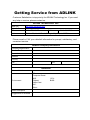
GEME-4000/H4000/S4000 5000/X5000/S5000 Series General Embedded Machine Engine User’s Manual © Copyright 2004 ADLINK Technology Inc. All Rights Reserved. Manual Rev.: 1.00 Date: April 25, 2006 Part Number: 50-1D002-200 The information in this document is subject to change without prior notice in order to improve reliability, design, and function and does not represent a commitment on the part of the manufacturer. In no event will the manufacturer be liable for direct, indirect, special, incidental, or consequential damages arising out of the use or inability to use the product or documentation, even if advised of the possibility of such damages. This document contains proprietary information protected by copyright laws. All rights are reserved. No part of this manual may be reproduced by any mechanical, electronic, or other means in any form without prior written permission of the manufacturer. Trademarks GEME® is a registered trademark of ADLINK Technology Inc. Other product names mentioned herein are used for identification purposes only and may be trademarks and/or registered trademarks of their respective companies. Getting Service from ADLINK Customer Satisfaction is top priority for ADLINK Technology Inc. If you need any help or service, please contact us. ADLINK TECHNOLOGY INC. Web Site http://www.adlinktech.com Sales & Service [email protected] TEL +886-2-82265877 Address 9F, No. 166, Jian Yi Road, Chungho City, Taipei, 235 Taiwan FAX +886-2-82265717 Please email or FAX your detailed information for prompt, satisfactory, and consistent service. Detailed Company Information Company/Organization Contact Person E-mail Address Address Country TEL FAX Web Site Questions Product Model Environment Detail Description Suggestions for ADLINK OS: Computer Brand: M/B: Chipset: Video Card: NIC: Other: CPU: BIOS: Table of Contents Introduction....................................................................................1 1.1 1.2 1.3 1.4 Product Overview............................................................................ 1 Unpacking Checklist........................................................................ 2 GEME Family .................................................................................. 3 1.3.1 Name Rule ............................................................................. 3 Specifications .................................................................................. 5 Base Unit ........................................................................................9 2.1 2.2 Dimensions ..................................................................................... 9 Base Unit Connector Pin Assignments.......................................... 13 2.2.1 VGA Connector...................................................... 13 2.2.2 USB Connector (2 Ports) ....................................... 13 2.2.3 AC input connector ................................................ 14 2.2.4 Ethernet (RJ-45) Connector ................................... 14 2.2.5 COM1/COM2 ......................................................... 15 2.2.6 Integrated PS/2 KBD/MS connector....................... 16 2.2.7 IEEE1394 Connector ............................................. 16 2.2.8 Compact Flash Connector ..................................... 17 2.2.9 Parallel Port connector........................................... 17 2.2.11 GPIO connector (GEME-H4000/X5000) .............. 18 2.2.12 DVI/LVDS, Audio Connector ................................ 19 Power Supply Unit.......................................................................21 3.1 3.2 Dimensions ................................................................................... 21 Specifications ................................................................................ 23 3.2.1 AC Power Supply................................................... 23 3.2.1 DC Power Supply................................................... 23 Getting Started.............................................................................25 4.1 IDE Boot Sequence Settings......................................................... 25 First/Second/Third/Other Boot Device ............................ 26 IRQ Information............................................................................. 27 Software Settings .......................................................................... 27 Software Support .......................................................................... 29 4.4.1 Operation System Support..................................... 30 4.4.2 Driver Support........................................................ 32 4.4.3 GEME Driver Installation List ................................. 33 4.2 4.3 4.4 Extension Modules......................................................................35 Table of Contents • i 5.0 Extension Modules Overview ........................................................ 35 5.0.1 Product series ........................................................ 35 MPC-8164 ..................................................................................... 36 5.1.1 Features................................................................. 36 5.1.2 CN2 Pin Assignments: Main connector.................. 37 ................................................................................................... 37 5.1.3 CN3 Pin Assignment: General Purpose DI/DO ports38 ................................................................................................... 38 5.1.4 MPC-8164 Dimensions .......................................... 38 MPC-8366/8372 ............................................................................ 39 5.2.1 Features................................................................. 39 5.2.2 Specifications......................................................... 39 5.2.3 SP1 Pin Assignment: I/O Connector of MPC-8372/6642 5.2.4 Dimensions ............................................................ 44 ................................................................................................... 45 MPC-7632/7632AU/7664 .............................................................. 46 5.3.1 Features................................................................. 46 5.3.2 Specifications......................................................... 46 5.3.3 CP1 Pin Assignment .............................................. 47 5.3.4 CP2 Pin Assignment .............................................. 48 5.3.5 Dimensions ............................................................ 49 PMC-RTV24G ............................................................................... 51 5.4.1 Features................................................................. 51 5.4.2 Specifications......................................................... 51 5.4.3 Pin Assignment ...................................................... 52 ................................................................................................... 52 5.4.4 Dimensions ............................................................ 53 PMC-3534G .................................................................................. 54 5.5.1 Features................................................................. 54 5.5.2 Specifications......................................................... 54 5.5.3 Pin Assignment ...................................................... 54 5.5.4 Dimensions ............................................................ 55 PMC-3544G .................................................................................. 56 5.6.1 Features................................................................. 56 5.6.2 Specifications......................................................... 56 5.6.3 Pin Assignment ...................................................... 56 ................................................................................................... 57 5.6.5 Dimensions ............................................................ 57 PMC-7841G .................................................................................. 58 5.7.1 Features................................................................. 58 5.7.2 Specifications......................................................... 58 5.7.3 Pin Assignment ...................................................... 58 5.1 5.2 5.3 5.4 5.5 5.6 5.7 ii • Table of Contents 5.8 5.7.4 Dimensions ............................................................ 59 PMC-7852G .................................................................................. 60 5.8.1 Features................................................................. 60 5.8.2 Specifications......................................................... 60 5.8.3 Pin Assignment ...................................................... 61 5.8.4 Dimensions ............................................................ 62 Appendix A: Important safety instructions ............................. 63 Appendix B: Warranty Policy ....................................................65 Table of Contents • iii 1 Introduction 1.1 Product Overview The General Embedded Machine Engine (GEME) 4000/5000 series is a complete embedded solution for Machine Automation/ Machine Vision/ Vision system integrators who are looking for a embedded controller to run their CPU-intensive applications. GEME is a rugged and compact chassis that supports an embedded SBC and power supply unit with optional storage peripherals, such as CompactFlash cards or a 2.5" HDD. Software compatibility, reliability and OS size issues can be avoided through its built-in embedded software. Although GEME is highly integrated, it can be further expanded with PMC modules and PC/104 extension modules supporting motion, vision, DIO, communications, and High Speed Link applications. With both hardware and software integrated in a single package, GEME is optimized for performance and will deliver the best reliability to our customers. Some important features of GEME are listed below: z Low power consumption, fanless CPU applied for embedded applications z Versatile functionalities: motion, vision, DIO, communications, High Speed Link z Expandable enclosure design for PMC and PC104 modules z Compact and rugged system design with wall-mounting kit z OS support: Windows CE, Windows XP Embedded, and Linux This chapter is designed to give you an overview of GEME’s platform. The chapter covers the following topics: • Unpacking Checklist • GEME Family • Specifications • Dimensions and Explode Drawing Introduction • 1 1.2 Unpacking Checklist Check the shipping carton for any damage. If the shipping carton and contents are damaged, notify the dealer for a replacement. Retain the shipping carton and packing material for inspection by the dealer. Obtain authorization before returning any product to ADLINK. Check the following items are included in the package, if there are any missing items, contact your dealer: Product GEME-4000/5000 series (Basic Base system) Included Items • All-in-one support CD-ROM (software & manuals) • Wall mounting kit: Wall mounting bracket (x4) M4 8mmScrew (8) • Power cord (L=1.8M, country of use to be specified while ordering) (for AC type only) • PS/2 Y cable • IDE flat cable (40 pin, L=57cm) • FDD flat cable (34pin, L=52cm) • 4-pin DC output harness for external drive (43cm) GEME-H4000/X5000/S • All-in-one support CD-ROM (software & manuals) 4000/S5000 series • Wall mounting kit: (Advanced Base Wall mounting bracket (x4) System) M4 8mmScrew (8) • Power cord (L=1.8M, country of use to be specified when ordering) (for AC type only) • PS/2 Y cable Note: (1) The packaging of the GEME OEM version with non-standard configuration, functionality, or package may vary according to different configuration requests. 2 • Introduction CAUTION: The board fitted inside the GEME system must be protected from static discharge and physical shock. Never remove any of the socketed parts except at a static-free workstation. Use the anti-static bag shipped with the product to handle the board. Wear a wrist strap grounded through one of the system's ESD Ground jacks when servicing system components. ! 1.3 GEME Family The GEME 4000/5000 family can be classified by CPU performance into the 4000 and 5000 series. It can be further distinguished by the availability of vision functionality and interfaces. Extension modules can be ordered to provide other functions not standard on the base unit. Please refer to the following table for available base units in the GEME family. 1.3.1 Name Rule GEME 4000 is the product series with Celeron M CPU and GEME-5000 is the product series with Pentium M CPU. GEME 4000, GEME-5000 start with Basic Base system. With several different specific PMC module installed, we call them Advanced Base system. On all the Base systems, several more PC-104 modules can be added. The Basic Base system is equipped with the IDE interface and FDD interface. nd With the 2 digit , it is used to identify the different CPU. Please refer to the below table for reference. CPU GEME-42000 / GEME-∀42000 Celeron M 1.0GHz GEME-52000 / GEME-∀52000 Pentium M 1.4GHz GEME-53000 /GEME-∀53000 Pentium M 1.1GHz Introduction • 3 The “∀” mark is the alphabet used to identify the different function, where : X: embedded PMC module with 4 channels video capture, which can support up to 120 fps H: embedded PMC module with H/W MPEG4. S: embedded PMC module with PCMCIA, CF and 2 USB2.0 ports 4 • Introduction 1.4 Specifications GEME-4000 SBC GEME-H4000 SBC Model No. CPU Cache System Memory Chipset VGA GEME-5000 GEME-X5000 EBC-P400 Ultra Low Voltage Celeron M 512 KB on-die Advanced Transfer Cache (ATC) Low Voltage Pentium M 1 MB/2 MB on-die Advanced Transfer Cache (ATC) One SODIMM socket for up to 1GB DDR333 Intel 855GME Graphics and Memory Controller Hub (GMCH) Intel I/O Controller Hub 4 (ICH4) z On-board VGA controller built-in AGP (3D hyper pipelined architecture) z Up to 1600 x 1200 in 32-bit color at 85Hz refresh rate Video memory sharing from main memory with Intel Dynamic Video Memory Technology (DVMT) z Up to 64 MB of dynamic video memory allocation DVI, LVDS 18-bit LVDS interface (Optional) DVI interface, compliant with DVI specification 1.0 TV-Out (Optional) BNC Connector BIOS Video Capture USB IEEE 1394 z Award BIOS, support PnP WIS H/W Four Conexant MPEG4 Fusion878A encoder Video decoder processor processor No No 4-CH CIF 4-CH compress, NTSC/PAL 4-CH CIF input preview Two USB ports, USB 2.0 compliant Texas Instruments TSB43AB23 1394a-2000 OHCI PHY/link-layer controller Three IEEE-1394 ports (two external , one internal) Ethernet Enhanced IDE CompactFlash Intel 82562EM 10BaseT/100BaseTx Bus Master IDE controller, EIDE interfaces for up to two devices, support PIO Mode 3/4 or Ultra DMA/100 IDE devices, including Hard Disk Drive, ATAPI CD-ROM, LS120, and ZIP drives. 50 pin socket for CompactFlash Type I/II Super I/O Chipset Winbond W83627HF Introduction • 5 Hardware Monitoring Built-in Winbond W83627HF, monitoring CPU temperature, voltage and battery,+3.3V,+5V,+12V voltage PC104 Interface Watchdog Timer COM1/ COM2: 16550 UART compatible ports with RS-232 interface,COM2 also supports RS-422,RS-485 One high-speed parallel port, SPP/EPP/ECP mode Combed PS/2 type mini-DIN connectors None 1 on-board 32-bit 33Mhz PMC module socket for functionally expansion 16-bit, PC/104 interface for functionally expansion Time-out timing select 1-255 seconds Dimensions 129mm x 167.5mm COM Ports Parallel Port Keyboard/Mouse Floppy Interface PMC Interface GEME-4000 System Power Supply (optional) GEME-H4000 GEME-5000 GEME-X5000 Universal input AC 100 VAC to 220 VAC, Max. output : +5V 11.5A, +12V 3A, -12V 0.5A DC input: 10VDC to 30VDC, Max. input current: 13A at 10VDC, Max. output: +5V 10A, +12V 1.5A, -12V 0.3A Operating Temp. -10˚-55˚C Humidity 0%-90% 183x140x95.36 mm (wall mount kit not included) [16.84 mm(H) for each extension kit ] With 512MB DDRAM With 512MB DDRAM +5V 4.0A, +12V 300mA +5V 5.5A, +12V 300mA Test conditions: (1) CPU 100% loading (2) No HDD, CD ROM, extension module +5V Max. 1A, +5V Max. 1A, None None +12V Max. 1A +12V Max. 1A Dimensions Power Consumption Power Output Storage GPIO (TTL) -10˚-50˚C -10˚-55˚C One 44-pin IDE One 44-pin IDE one 44-pin IDE one 44-pin IDE removable removable HDD HDD HDD HDD none Four digital input, Four digital output, none Operating System Windows CE, Windows XP Embedded, Linux 6 • Introduction -10˚-50˚C Four digital input, Four digital output, Operating: 5-100Hz, 0.00142 g2/Hz; 100-500Hz, -6dB/Octave, 0.5Grms, 3axes, 30 minutes/axis Random Vibration Non-operating: 5-100Hz , 0.02g2/Hz ; 100-500Hz , -6dB/Octave, 1.88Grms, 3 axes,1hr/axis (IEC 68-2-64) Warning! Always disconnect the power cord from your chassis whenever you are working on it. Do not connect the power cord while the power switch is on. A sudden rush of power can damage sensitive electronic components. Only authorized and experienced electronics personnel should open the chassis. Caution! Always ground yourself to remove any static electric charge before touching GEME. Modern electronic devices are very sensitive to static electric charges. Use a grounding wrist strap at all times. Place all electronic components on a static-dissipative surface or in a static-shielded bag. Introduction • 7 2 Base Unit This chapter will familiarize the user with available GEME interfaces and connections before getting started and includes the following information: 2.1 • Dimensions • Base Unit Connector Pin Assignments Dimensions Base Unit • 9 TOP VIEW SIDE VIEW COM2 LPT1 CF PWR ACT/LINK RESET HDD 10/100M LAN KB/MS IEEE1394 VGA USB COM1 HDD SPK OUT MIC IN CF POWER SUPPLY INPUT : 100~240VAC 50~60Hz POWER FRONT VIEW Figure 1. 10 • Base Unit GEME-4000/5000 base unit dimensions TOP VIEW SIDE VIEW COM2 LPT1 CF PWR ACT/LINK RESET HDD 10/100M CH0 LAN KB/MS CH1 CH2 IEEE1394 CH3 VGA USB COM1 GPIO POWER SUPPLY INPUT : 100~240VAC 50~60Hz POWER FRONT VIEW Figure 2. GEME-H4000/X5000 base unit dimensions Base Unit • 11 TOP VIEW SIDE VIEW COM2 LPT1 CF PWR ACT/LINK RESET HDD 10/100M LAN KB/MS IEEE1394 USB VGA POWER SUPPLY INPUT : 100~240VAC 50~60Hz Figure 3. 12 • Base Unit COM1 PCMCIA USB POWER GEME-S4000/S5000 dimensions 2.2 Base Unit Connector Pin Assignments Detailed descriptions and pin-outs for each connector are given in the following sections. 2.2.1 VGA Connector GEME provides a VGA controller for a high resolution VGA interface. It supports VGA and VESA, up to 1280 x 1024 @ 24 bpp, and video memory sharing from main memory with Intel Dynamic Video Memory Technology (DVMT). Memory size is controlled by the device driver from 1 MB up to 11 MB Signal Name Red Blue GND GND +5V N.C. HSYNC DDCCLK Pin 1 3 5 7 9 11 13 15 Pin 2 4 6 8 10 12 14 Signal Name Green N.C. GND GND GND DDCDAT VSYNC 2.2.2 USB Connector (2 Ports) The USB connectors can be used for connecting any device that conforms to the USB 2.0 specification. Many recent digital devices conform to this standard. The USB interface supports Plug and Play and Hot Swapping, which recognizes devices automatically and enables you to connect or disconnect a device whenever you want without powering down the computer. ♦ GEME provides two connectors for USB interfaces ♦ Plug & Play and hot swapping for up to 127 external devices is supported. ♦ Compliant with USB Specification Rev. 2.0; individual over-current protection. Pin # 1 2 3 4 Signal Name VCC USBUSB+ Ground Base Unit • 13 2.2.3 AC input connector GEME comes with an AC inlet connector that carries 100~240 VAC external power input, and features reversed wiring protection. PIN 1 2 3 SIGNAL Neutral Line Earth Ground 2.2.4 Ethernet (RJ-45) Connector GEME is equipped with Intel Ethernet LAN controller that is fully compliant with IEEE 802.3u 10/100Base-T CSMA/CD standards. The Ethernet port provides a standard RJ-45 jack on board, and LED indicators on the front side to show its Speed (Yellow LED) and Active/Link (Green LED) status. Pin 1 2 3 4 5 6 7 8 Signal Name TD+ TDRD+ NC NC RDNC NC LAN status LED LED Color Yellow (Speed status) Green (Link status) Status ON OFF ON OFF Blinking 14 • Base Unit Function 100Mbps 10Mbps Link Link off Data transfer in progress 2.2.5 COM1/COM2 GEME offers two serial communications interface ports: COM 1 and COM 2. IRQ and Address Setting The IRQ and I/O address range are both assigned by BIOS. The table below describes COM1/COM2 default settings: COM Port COM 1 COM 2 Mode RS-232 RS-232 Bass address 3F8h 2F8h IRQ IRQ4 IRQ3 COM1/COM2 Pin Assignment Pin 1 2 3 4 5 6 7 8 9 RS-232 DCD, Data carrier detect RXD, Receive data TXD, Transmit data DTR, Data terminal ready GND, ground DSR, Data set ready RTS, Request to send CTS, Clear to send RI, Ring indicator Note: COM2 can also support RS422 or RS485 (with Auto direction function) by adjusting jumper. The customer has to request this feature while placing the order. COM 2 6 1 9 5 Pin no. 1 2 3 4 5 6 7 RS422 TXTX+ RX+ RXGND --- RS485 DD+ --GND --- Base Unit • 15 8 9 --- --- 2.2.6 Integrated PS/2 KBD/MS connector GEME has a proprietary interface for PS/2 keyboard and mouse connections. A 6-pin mini-DIN connector is located on the rear panel of GEME. A proprietary ADLINK Y-cable is used to convert the 6-pin mini-DIN connector to two 6-pin mini-DIN connectors for the PS/2 keyboard and PS/2 mouse connections. The power provided to the keyboard and mouse is protected by a polyswitch rated at 1.1A. PIN 1 2 3 4 5 6 SIGNAL KBDAT MSDAT GND KBMS5V KBCLK MSCLK FUNCTION Keyboard Data Mouse Data Ground Power Keyboard Clock Mouse Clock 2.2.7 IEEE1394 Connector GEME comes with two IEEE 1394 interfaces, which are fully Plug & Play compliant and hot swappable. GEME’s IEEE 1394 interface fully supports the IEEE 1394-1995 standard for high-performance serial bus and the IEEE 1394a-2000 supplement. Full IEEE 1394a-2000 support includes: connection debounce, arbitrated short reset, multi speed concatenation, arbitration acceleration, fly-by concatenation, and port disable/suspend/resume. GEME has two IEEE 1394a-2000 fully compliant cable ports with transfer rates of 100/200/400 megabits per second (Mbits/s). PIN 1 2 3 4 5 6 16 • Base Unit SIGNAL +12V GND TPB0TPB0+ TPA0TPA0+ 2.2.8 Compact Flash Connector GEME’s standard CompactFlash (CF) socket has an ATA interface that is fully compatible with an IDE HDD and supports both type-I and type-II CF cards. The CF socket is on the Secondary IDE port. 2.2.9 Parallel Port connector Parallel I/O interface signals are routed to a DB25 socket on the front panel. This port supports full IEEE-1284 capability and provides a basic printer interface that supports EPP and ECP enhanced port modes IRQ and Address Setting The IRQ, I/O address range and mode are all assigned by BIOS. The following table outlines the parallel port default settings: Parallel Port Mode SPP Bass address 378h IRQ IRQ7 Signal Name Pin # Pin # Signal Name Line printer strobe PD0, parallel data 0 PD1, parallel data 1 PD2, parallel data 2 PD3, parallel data 3 PD4, parallel data 4 PD5, parallel data 5 PD6, parallel data 6 PD7, parallel data 7 ACK, acknowledge Busy Paper empty Select 1 2 3 4 5 6 7 8 9 10 11 12 13 14 15 16 17 18 19 20 21 22 23 24 25 N/A AutoFeed Error Initialize Select Ground Ground Ground Ground Ground Ground Ground Ground N/A Base Unit • 17 2.2.10 Video Capture BNC connector (GEME-H4000/X5000) GEME accepts 4 channels standard composite color (PAL, NTSC) or monochrome video formats (CCIR, EIA). Video resolution is programmable including the square-pixel (640 x 480 or 768 x 576) and the broadcast resolution. PIN SIGNAL 1 Video Signal 2 GND 2.2.11 GPIO connector (GEME-H4000/X5000) GEME’s I/O lines are TTL compatible and support single-input, single-output and single-software trigger lines. PIN 1 2 3 4 5 6 7 8 SIGNAL Digital Input 0 Digital Input 1 Digital Input 2 Digital Input 3 GND Digital Output 0 Digital Output 1 Digital Output 2 PIN 9 10 11 12 13 14 15 SIGNAL Digital Output 3 GND GND GND GND GND +5V The I/O lines are internally pulled up and have the following characteristics: Voltage Input high voltage (5μA) Input low voltage (-5μA) Output high voltage (-1.0mA) Output low voltage (100.0mA) MIN 2.0 V 0.0V 5.0V - Software trigger output : Programmable trigger scale, from 60uS ~ 16mS 18 • Base Unit MAX 5.25V 0.80V 0.5V 60uS ~16mS Trigger Signal 2.2.12 DVI/LVDS, Audio Connector Base Unit • 19 3 Power Supply Unit The entire GEME series can support either AC or DC power supplies per application requirements. The power supply unit is internally integrated into GEME system. This chapter shows the following detailed information: 3.1 • Dimensions • Specifications Dimensions TOP VIEW POWER SUPPLY INPUT : 100~240VAC 50~60Hz SIDE VIEW POWER FRONT VIEW Figure 4. GEME AC type power supply unit dimensions Power Supply Unit • 21 TOP VIEW SIDE VIEW POWER SUPPLY INPUT : 10~30VDC Max. 13A@10VDC POWER FRONT VIEW Figure 5. GEME DC type power supply unit dimensions 22 • Power Supply Unit 3.2 Specifications 3.2.1 AC Power Supply The AC power supply is a triple output 110W switching power supply, which is designed to meet Harmonics EN61000-3-2. Input Specifications Input voltage Input frequency Input current Inrush current The range of input voltage is from 91VAC to 264VAC. The nominal voltage is 115VAC 60Hz and 230VAC 50Hz. The range of input frequency is from 47Hz to 63Hz The maximum input current is 2A at 115VAC 1A at 230VAC The inrush current will not exceed 30A at 115VAC input or 60A at 230VAC input, cold start, 25 degree C Output Specifications Output +5V +12V - 12V Rated load 11.5A 3A 0.5A Peak load 15A 5A 0.5A International Standards Safety standards EMI standards EMS standards UL 60950 CSA 22.2 NO.234 EN 60 950 FCC docket 20780 curve “B" EN 55022“B" EN 61000-3-2 EN61000-4-2 6KV contact discharge, 8KV air discharge criteria A EN61000-4-3 10V/m Criteria A EN61000-4-4 2KV Criteria A 3.2.1 DC Power Supply The DC power supply is a 72 Watt triple-output switching power supply, specially designed for microprocessor-based applications; DC input from 10V to 30V; enclosed type. Power Supply Unit • 23 Input Specifications Input voltage Input current Inrush current This power supply can operate continuously from +10VDC to +30VDC, normal line is +24VDC. The maximum input current is 13A at 10VDC The maximum inrush current will not exceed 25A at 12VDC input from a cold start, with exclusion of EMI capacitors Output Specifications Output +5V +12V - 12V Rated load 10A 1.5A 0.3A Peak load 14A 3A International Standards Safety standards EMI standards EMS standards 24 • Power Supply Unit UL 1950 CSA 22.2 No. 234 VDE EN 60950 FCC docket 20780 curve “B” EN55022 class ”B” IEC-801-2 8KV air discharge IEC-801-3 3V/M IEC-801-4 2KV 4 Getting Started 4.1 IDE Boot Sequence Settings IDE device1 IDE device 3 IDE device 2 IDE Primary Master HDD-0 -- -- HDD-0 HDD-0 IDE Primary Slave -- HDD-0 -- HDD-1 IDE Secondary Master -- -- HDD-0 -- -- HDD-0 HDD-0 HDD-1 HDD-1 HDD-1 HDD-2 -- The Phoenix-Award BIOS provides a Setup utility program for specifying system configuration and settings. The Setup utility is stored in BIOS ROM. When you power up the system, BIOS is activated. Immediately pressing the <Del> key allows you to enter the Setup utility. If you are slow to press the <Del> key, POST (Power On Self Test) will continue with its test routines, thus preventing you from invoking Setup. If you still wish to enter Setup, restart the system by pressing the “Reset” button or simultaneously pressing the <Ctrl>, <Alt> and <Delete> keys. You can also restart by turning the system off and back on again. On power up, the following message will appear on the screen: Press <DEL> to Enter Setup In the Setup utility program, you can make changes by pressing the arrow keys to highlight items, <PgUp> and <PgDn> keys to change entries, <Enter> to select, <F1> for help and <Esc> to quit. When you enter the Setup utility, the Main Menu screen will appear on the screen. The Main Menu allows you to select from various setup functions and exit choices. Phoenix-AwardBIOS CMOS Setup Utility Getting Started • 25 ► Standard CMOS Feature ► Advanced BIOS Features ► Advanced Chipset Features ► Integrated Peripherals ► Power Management Setup ► PnP/PCI Configurations ► PC Health Status ► Frequency/Voltage Control Load Fail-Safe Defaults Load Optimized Defaults Set Supervisor Password Set User Password Save & Exit Setup Exit Without Saving ESC : Quit Ç È Æ Å : Select Item F9 : Menu in BIOS F10 : Save & Exit Setup Time, Date, Hard Disk Type For IDE boot sequence setting, please select “Advanced BIOS Feature”: Phoenix – AwardBIOS CMOS Setup Utility Advanced BIOS Features Virus Warning Disabled CPU Internal Cache Enabled External Cache Enabled CPU L2 Cache ECC Checking Enabled Quick Power On Self Test Enabled First Boot Device Floppy Second Boot Device HDD-0 Third Boot Device LS120 Boot Other Device Enabled Swap Floppy Drive Disabled Boot Up Floppy Seek Enabled Boot Up NumLock Status On Gate A20 Option Fast Typematic Rate Setting Disabled Typematic Rate (Chars/Sec) 6 Typematic Delay (Msec) 250 Security Option Setup OS Select For DRAM > 64MB Non-OS2 Ç È Æ Å : Move Enter : Select F5 : Previous Values +/-/PU/PD : Value Item Help Menu Level F10 : Save F6 : Fail-Safe Defaults ESC : Exit ► F1 : General Help F7 : Optimized Defaults First/Second/Third/Other Boot Device BIOS attempts to load the operating system from the devices in the sequence selected in the following items. The settings are: Disabled HDD-0 HDD-1 ZIP100 Floppy SCSI HDD-2 LAN LS120 CDROM HDD-3 HDD-0, HDD-1, HDD-2 are for IDE device, and HDD-3 is not used. 26 • Getting Started 4.2 IRQ Information The IRQ & base address settings in the GEME system are according to the “assembly order” of the PC104 cards in GEME system. Please see the follow illustration: Base Unit 1st PC104 card 2nd PC104 card 3rd PC104 card Power Supply Unit I/O Address IRQ No. Memory Address 4.3 1st PC104 card 300 9 D0000 2nd PC104 card 200 5 D4000 3rd PC104 card 280 10 D8000 Software Settings GEME system software is well installed before shipping according to the customers’ configuration options. This section provides the necessary information for the customers who need to rebuild OS. Step1: Check IRQ resources setting in BIOS.(Please set the IRQ number according to your system configuration and see the details on section 4.3). For example, you have to change the settings of IRQ 5, 9, 10 as “Legacy ISA” in BIOS if there are three PC 104 cards in GEME. The remaining IRQ settings are as “PCI/ISA PnP”. When you boot up GEME, press “DEL” key to enter BIOS setting screen as follows. Getting Started • 27 Step2: You have to register your PC104 card in Windows system. For example, you can find the “Registry Utility” from MPC-8372 folder after installing the MPC-8372 driver. The screen is as follows. If you have other PC 104 module in GEME, you can also find the corresponding utility. After pressing “New” button in the above screen, you will see the “Device Configuration” dialog. Please add the corresponding PC104 card information depending on how many cards you have in GEME. For example, you can add 28 • Getting Started one MPC-8372 card in the dialog if there is only one MPC-8372 in GEME. Please press “New” to the next step. Refer to the table in section 4.3 to select the “Base Address”, “IRQ”, and “Mem Address”. For example, the setting is as following dialog if you have one MPC-8372 card in GEME. Press the “OK” button to save this setting. It will take effect after you reboot Windows system. 4.4 Software Support If you liken GEME to a human body, the I/O would be the eyes, ears, hands, and feet; the CPU and bus the nervous system; and the software the brain, the “organ” that coordinates every operation of GEME. Hence, the operating Getting Started • 29 system’s importance is beyond comparison as it is responsible for managing core tasks and resource allocation for the hardware. It not only affects future system execution time and efficiency, but also resource requirements during software development for the whole application. Selecting a suitable OS suitable for different application requirements is an important task for system developers. When choosing an OS, they need to consider these points: stability, real-time capability, multitasking, human-machine interface (or GUI), memory size, and total cost (including application development costs, licensing costs for multiple copies, software engineering manpower, maintenance costs, etc). There isn’t necessarily only one correct choice. System developers should look at the overall situation and focus on what provides the optimal solution for the developed system when considering this issue. In this respect, GEME is allows system developers maximum flexibility by being compatible with several operating systems. 4.4.1 Operation System Support Windows 2000/XP Windows2000/XP supports GEME’s chipset drivers, allowing the user to install Windows 2000/XP themselves. ADLINK also provides OS pre-installation service for Windows 2000/XP on GEME (with a Windows 2000/XP license pre-purchased from ADLINK). As Windows 2000/XP requires a large amount of storage space, a harddrive is the best solution storage choice for GEME running Windows 2000/XP. Linux Most Linux versions (e.g. RedHat, Suse, etc) also support GEME’s chipset drivers, allowing users to install Linux themselves). As Linux also requires a large amount of storage space, a hard drive is the best solution storage choice for GEME running Linux. Windows XP Embedded Windows XP is a multitasking OS known for its stability. As a result of its overwhelming popularity, human-machine interfaces, and plentiful development tools, developing applications in Windows XP is comparatively simple. Microsoft carried over the advantages of Windows XP when releasing Embedded XP. The concept behind the design of Embedded XP is simply a modularized Windows XP. System developers only select the needed Windows XP components and functions and then organize them together to construct an XP Embedded OS. By using this architectural modularization, system integrators can readily reduce the storage space requirements of XP Embedded. The only factor determining storage space requirements is the number of function modules needed. Because XP Embedded is completely compatible with Windows XP, 30 • Getting Started developers can compile controller software in the Windows XP environment, and then transfer the code to Embedded XP for immediate use. System developers do not need to learn any new tools to use XP Embedded. Their experience on Windows XP can be directly transferred to XP Embedded, thus lowering software development costs. Another advantage is that the cost of licensing Embedded XP is much less than that of Windows XP. Currently ADLINK provides the standard XP Embedded OS image for GEME (customers must pre-purchase an XP Embedded license from ADLINK), The standard XP Embedded OS image provided by ADLINK is about 200 MB for the English language version, and 400 MB for Chinese language version. For this OS configuration, a CF card is the best storage device for GEME. The major functions inside the standard XP Embedded OS image are as follows • XP Embedded OS Kernel • Drivers for GEME H/W and peripheral cards • TCP/IP Networking • TCP/IP with file sharing and client for Microsoft network • Internet Explorer • File Manager • Language Support The standard XP Embedded OS image can meet most application needs. If the customer has special functional requirements for XP Embedded, please contact ADLINK’s field application engineers (FAE) for more detail about this OEM service. Windows CE Windows CE 4.2 incorporates a fresh new look. Because Windows CE is designed with embedded systems in mind, it requires much less storage space than does XP Embedded. Windows CE typically needs 64MB of storage space and it is possible to reduce this amount if necessary. An important feature of Windows CE supports real-time functionality. Microsoft has tried to keep API naming conventions and the development process consistent between Windows CE and Windows XP. But because Windows CE has an embedded architecture (as compared with Windows XP’s desktop system concept), the software development process will have significant differences. Newcomers to the embedded world must keep this in mind. Another factor to consider when deciding whether to use Windows CE is that licensing costs are much less than XP Embedded, thanks to Microsoft’s recent promotions. Getting Started • 31 Currently ADLINK offers the standard WinCE OS image for GEME (customer must purchase the WinCE license from ADLINK), The standard WinCE OS image requires about 25 MB for the English language version, and 30 MB for the Chinese language version. For this OS configuration, a CF card is the best storage device for GEME. The major functions included with the standard WinCE OS image are as follows. • WinCE OS Kernel • Drivers for GEME H/W and peripheral cards • TCP/IP Networking • Internet Explorer • File Manager • Language Support The standard WinCE OS image can meet most application requirements. If the customer has special functional requirements for WinCE, please contact ADLINK’s FAE for more details about this OEM service. 4.4.2 Driver Support Driver support for GEME’s peripheral cards under the different OS systems are outlined in the following table. Users can find drivers for these peripheral cards in ADLINK ALL-IN-ONE CD (Automation): Motion Cards Module No. Bus Interface MPC-8164 PC104 MPC-8372/ 8366 PC104 Description Win2000, XP & eXP driver Win CE driver Linux driver Ready Ready Ready Ready Call for status Call for status 4-axis pulse type motion 12/6-axis SSCNET motion Communication Cards Module No. Bus Interface PMC-3534G PMC PMC-3544G PMC PMC-7841G PMC 32 • Getting Started Description 4 port asynchronous serial comm.. 4 port RS-422/485 isolated serial comm.. CAN bus communication card Win2000, XP & eXP driver Win CE driver Linux driver Ready Ready Ready Ready Ready Ready Ready Call for status Call for status HSL Card Module No. Bus Interface Description Win2000, XP & eXP driver Win CE driver Linux driver PMC-7852G PMC HSL Serial I/O master card Ready Ready Ready DIO Card Module No. Bus Interface Description Win2000, XP & XP driver Win CE driver Linux driver MPC-7632/64 PC104 32/64 CH Digital I/O Ready Ready Ready 4.4.3 GEME Driver Installation List GEME add-on cards Vision WinXP/2k Built-in OS Built-in OS WinXP embedded*(1) Test & registration programs are built-in ADLINK standard image(C:\ADLINK) View Creator utility is built-in ADLINK standard image(C:\ADLINK\ Angelo) WinCE Built-in ADLINK standard image Built-in ADLINK standard image Linux*(2) .. Kernel 2.6.9 Getting Started • 33 Note*(1) ADLINK will pre-install the hardware driver, utility, and runtime library on GEME. For developing program in the Host PC, the user must install the corresponding software package with ADLINK all-in-one CD. Note*(2) Please check with ADLINK FAE about WinCE & Linux *** With the ADLINK-ALL-IN-ONE (Automation) CD, users can install drivers for Windows 2000/XP systems. For XP Embedded systems, if the XP Embedded OS is built by ADLINK, ADLINK will pre-install the drivers for GEME’s peripheral cards in the OS image. If users build XP Embedded OS image, they can also use ADLINK-ALL-IN-ONE (Automation) CD for driver installation. *** Currently the Linux drivers ADLINK provides for GEME’s peripheral cards are based on Kernel 2.4.18 (RedHat 7.3 compatible). ADLINK also provides Kernel 2.4.20 (RedHat 8.0 and 9.0 compatible) and Kernel 2.4.22(RedHat compatible) driver re-compiler service for customers. If users require this service, please contact ADLINK’s FAE for more details. For driver support for other Linux releases, please contact ADLINK’s FAE for current support status. 34 • Getting Started 5 Extension Modules 5.0 Extension Modules Overview 5.0.1 Product series GEME system is designed to be extendable by one PMC and up to 3 PC104 modules. This chapter provides information about compatible extension modules: Function Bus Motion PC104 MPC-8164 4-axis stepping & servo motion control card PC104 MPC-8372 12-axis SSCNET servo motion control card PMC PMC-3534G 4-port RS-232 serial communication module PMC PMC-3544G 4-port RS-422/RS-485 serial communication module PMC PMC-7841G CAN bus communication card HSL PMC PMC-7852G High Speed Link master controller interface module DIO PC104 MPC-7632 32-CH Digital I/O module PC104 MPC-7664 64-CH Digital I/O module Comm. Model Name. Description Note. If you need more detailed information about the above cards, please see the specific manuals. Extension Modules • 35 5.1 • • • • • • • • • • • • • • • • • • • • • • • • • • MPC-8164 5.1.1 Features 16-bit PC104 Bus axes of step and direction pulse output for controlling stepping or servomotor Maximum output frequency of 6.55 MPPS Pulse output options: OUT/DIR, CW/CCW Programmable acceleration and deceleration time for all modes Trapezoidal and S-curve velocity profiles for all modes Any 2 of 4 axes circular interpolation Any 2-4 of 4 axes linear interpolation Continuous interpolation for contour following motion Change position and speed on the fly Change speed by comparator condition 13 home return modes with auto searching Hardware backlash compensator and vibration suppression Software end-limits for each axis 28-bit up/down counter for incremental encoder feedback Home switch, index signal(EZ), positive, and negative end limit switches interface on all axes 2-axis high speed position latch input 2-axis position compare trigger output with 4k FIFO auto-loading All digital input and output signals are 2500Vrms isolated Programmable interrupt sources 8 channels of general purpose photo-isolated digital inputs 8 channels of general purpose open collector digital outputs Software supports a maximum of up to 4 MPC-8164 cards (16 axes) operation in one system Includes Motion Creator, Microsoft Windows-based application development software MPC-8164 Libraries and Utilities for DOS and Windows 98/NT/2000/XP. Also support Windows XP/NT Embedded MPC-8164 Libraries for Linux and Windows CE systems 36 • Extension Modules 5.1.2 CN2 Pin Assignments: Main connector CN2 is the major connector for the motion control I/O signals. No. 1 2 3 4 5 6 7 8 9 10 11 12 13 14 15 16 17 18 19 20 21 22 23 24 25 26 27 28 29 30 31 32 33 34 35 36 37 38 39 40 41 42 43 44 45 46 47 48 49 50 Name VPP GND OUT1+ OUT1DIR1+ DIR1SVON1 ERC1 ALM1 INP1 RDY1 GND EA1+ EA1EB1+ EB1EZ1+ EZ1VPP GND OUT2+ OUT2DIR2+ DIR2SVON2 ERC2 ALM2 INP2 RDY2 GND EA2+ EA2EB2+ EB2EZ2+ EZ2PEL1 MEL1 CMP1 SD/PCS1 ORG1 GND PEL2 MEL2 CMP2 SD/PCS2 ORG2 GND GND GND I/O Function (axisc/d) O +5V power supply output Ext. power ground O Pulse signal (+),c O Pulse signal (-),c O Dir. signal (+),c O Dir. signal (-),c O Multi-purpose signal, c O Dev. ctr, clr. signal, c I Alarm signal, c I In-position signal, c I Multi-purpose signal, c Ext. power ground I Encoder A-phase (+), c I Encoder A-phase (-), c I Encoder B-phase (+), c I Encoder B-phase (-), c I Encoder Z-phase (+), c I Encoder Z-phase (-), c O +5V power supply output Ext. power ground O Pulse signal (+), d O Pulse signal (-), d O Dir. signal (+), d O Dir. signal (-), d O Multi-purpose signal, d O Dev. ctr, clr. signal, d I Alarm signal, d I In-position signal, d I Multi-purpose signal, d Ext. power ground I Encoder A-phase (+), d I Encoder A-phase (-), d I Encoder B-phase (+), d I Encoder B-phase (-), d I Encoder Z-phase (+), d I Encoder Z-phase (-), d I End limit signal (+), c I End limit signal (-), c O Position compare output c I Ramp-down signal c I Origin signal, c Ext. power ground I End limit signal (+), d I End limit signal (-), d O Position compare output d I Ramp-down signal d I Origin signal, d Ext. power ground Ext. power ground Ext. power ground No. 51 52 53 54 55 56 57 58 59 60 61 62 63 64 65 66 67 68 69 70 71 72 73 74 75 76 77 78 79 80 81 82 83 84 85 86 87 88 89 90 91 92 93 94 95 96 97 98 99 100 Name VPP GND OUT3+ OUT3DIR3+ DIR3SVON3 ERC3 ALM3 INP3 RDY3 EXGND EA3+ EA3EB3+ EB3EZ3+ EZ3VPP GND OUT4+ OUT4DIR4+ DIR4SVON4 ERC4 ALM4 INP4 RDY4 GND EA4+ EA4EB4+ EB4EZ4+ EZ4PEL3 MEL3 LTC3 SD/PCS3 ORG3 GND PEL4 MEL4 LTC4 SD/PCS4 ORG4 GND E_24V E_24V I/O Function (axise/f) O +5V power supply output Ext. power ground O Pulse signal (+), e O Pulse signal (-),e O Dir. signal (+), e O Dir. signal (-), e O Multi-purpose signal, e O Dev. ctr, clr. signal, e I Alarm signal, e I In-position signal, e I Multi-purpose signal, e Ext. power ground I Encoder A-phase (+), e I Encoder A-phase (-),e I Encoder B-phase (+),e I Encoder B-phase (-),e I Encoder Z-phase (+),e I Encoder Z-phase (-),e O +5V power supply output Ext. power ground O Pulse signal (+),f O Pulse signal (-),f O Dir. signal (+),f O Dir. signal (-),f O Multi-purpose signal, f O Dev. ctr, clr. signal, f I Alarm signal, f I In-position signal, f I Multi-purpose signal, f Ext. power ground I Encoder A-phase (+), f I Encoder A-phase (-), f I Encoder B-phase (+), f I Encoder B-phase (-), f I Encoder Z-phase (+), f I Encoder Z-phase (-), f I End limit signal (+), e I End limit signal (-), e I Position latch input e I Ramp-down signal e I Origin signal, e Ext. power ground I End limit signal (+), f I End limit signal (-), f I Position latch input, f I Ramp-down signal f I Origin signal, f Ext. power ground Ext. power supply, +24V Ext. power supply, +24V Extension Modules • 37 5.1.3 CN3 Pin Assignment: General Purpose DI/DO ports CN3 Pin No 1 3 5 7 9 11 13 15 17 19 21 23 25 Signal Name DOCOM DOCOM DO0 DO2 DO4 DO6 -DICOM DICOM DI1 DI3 DI5 DI7 CN3 Pin No 2 4 6 8 10 12 14 16 18 20 22 24 26 5.1.4 MPC-8164 Dimensions Figure 6. 38 • Extension Modules MPC-8164 PCB Layout Signal Name DOCOM DOCOM DO1 DO3 DO5 DO7 DICOM DICOM DI0 DI2 DI4 DI6 -- CN3 (DIO) CN2 (MOTION) BUSY MPC-8164 183 Figure 7. 5.2 MPC-8164 Front panel MPC-8366/8372 5.2.1 Features MPC-8366/72 are 6/12-axis serial connection motion controller. They provide the advanced features as follows. • PC/104 interface • Servo interface: SSCNET II protocol (Update rate: 0.888 ms) • Up to 6/12 axes • 32-bit command resolution • On-line servo tuning and data monitoring • Easy wiring up to 30 meters • Multiple axes linear interpolation • Any 2 axes circular interpolation • Contour following motion • On-the-fly motion/ velocity change • Programmable interrupt source • Two 16-bit analog input channels. • 32-bit external encoder channels • Two differential pulse output channels • Software support Windows 2K/XP TM • MotionCreator and Trajectory Generator utility 5.2.2 Specifications The following lists summarize the main specifications of the MPC-8366/72 board motion control system. System Item Bus Type for PCI board Bus Type for MPC board Bus width for PCI/MPC Bus Voltage Memory usage Description PCI Rev. 2.2, 33MHz PC/104 32-bit / 16-bit 5V 16KByte Extension Modules • 39 IRQ on PCI board IRQ on MPC board Operating temperature Storage temperature General Specifications Humidity Power Consumption Type Clock DSP performance I/O Connector Board Interface SSCNet Connector Protocol Driver Bit Rate Communicati Physical layer on Maximum working length Error detection Max. No of controllable axes Servo update rate DSP Servo Loop Servo Data Monitors Servo parameter tuning Motion Velocity Profile Single motion Home move Motion Function Continuous motion Application Functions Interrupt Move Ratio Software Limit Position Compare Interlock System error check During operation stop 40 • Extension Modules Assigned by PCI controller Assigned by Software Utility 0°C ~ 60°C -20°C ~ 80°C 5 ~ 95%, non-condensing PCI (MPC)-8372/8366: +5V @ 1 A typical TI TMS320C6711 100MHz 600 MFLOPS 68-pin VHDIC 3M 10220-52A2JL SSCNET II 5.625Mhz RS-485 30m for each 6 axes CRC 8372 :12 ; 8366 : 6 0.888ms Current position Droop (deviation) Velocity Command Velocity feedback Torque command Servo alarm number …etc Parameter read/write Trapezoidal & S-Curve Jog move Single axis P to P motion Change P/V on the fly Linear interpolation: up to 4 axes 2-axis Circular interpolation 2 home mode Start / End motion list Add linear trajectory Add arc trajectory: 2 axes Add Dwell Smooth Trajectory Start/Sop command Load Trajectory from file Motion I/O status read/configure Motion status In unit of Pulse per mm Each axis has 2 soft limits Each axis has 2 comparators 2 axes interlock system Watchdog timer Possible to select conditions where interrupt occurs Optical Isolated Digital Input During alarms, etc. +Limit Switch x 12 (PEL) -Limit Switch x 12 (MEL) Proximity dog x 12 (ORG) General Purposed Input x 2 (PCI board only) Emergency Stop x 1 Digital Output DO x 2 Analog Out Analog In Encoder Interface DA x 2 AD x 2 (Available for MPC/cPCI board) 32-bit Encoder input (A,B,Z) x 3 channel ( PCI board ) 2 channel ( MPC/cPCI board ) 2 channel differential pulses Pulse Output output (Available for MPC/cPCI board) Yes z Sink or source type are selectable in all channels (all channels must be the same) z Input voltage range: 0 ~ 24V Logic H: 14.4~24V Logic L: 0~5V z Input resistor: 4.7KΩ @ 0.5W z DI change of state detection z Isolated voltage: 500 Vrms z Bandwidth: 10K Hz (0.1 ms) z Output type: Open-collector (PC3H7) z Sink Current: 6.5mA Min. z Isolated voltage: 500 VDC z Bandwidth: 10K Hz(0.1 ms) z Resolution: 16 bits z Settling Time: 10μS Max. z Output Range: ±10V z Output Coupling: DC z Output Impedance: 30Ω Max. z Output Driving: ±5mA max. z Power On State: Floating z Calibration: Self-Calibration z Gain Error: ±3% Max. z Offset Error: 1mV Max. for PCI board 0.2mV Max. for MPC board z Resolution: 16 bits, no missing code z Sampling Rate: 250kS/s z Programmable Input Range: ±10V, ±5V, ±2.5V z Calibration: Self-Calibration z Gain Error: ±0.03% Max. z Offset Error: 0.2mV Max. z Incremental Encoder Input Max. Speed : 5Mhz z Input Voltage: 0 - 5V dc z Logic H: 3~5V z Logic L: 0~2.4V z Input resistor: 220Ω @ 0.125W z Isolated voltage:500 Vrms z OUT/DIR, CW/CCW, AB phase selectable z Max. Output Frequency: 4.16 MHz Extension Modules • 41 z Isolated voltage:500 Vrms Aux. DIO No. 1 2 3 4 5 6 7 8 9 10 11 12 13 14 15 16 17 18 19 20 21 Board to board synchronous interface (PCI board only) CN4 6 TTL Level Digital Output (at CN3 on Extension bracket of PCI board only) z Voltage output high: Typical: 5V Min: 2.4v @ 15mA z Voltage output low: Typical: 0.3V @ 24mA Max: 0.5V Optional bracket for SSCNET Axis 7-12 splitter and TTL Level Digital Output for PCI-8372 only CN3 (A) , CN2 (A) 5.2.3 SP1 Pin Assignment: I/O Connector of MPC-8372/66 Name DO_COM PEL1/MDI1 MEL1/MDI2 ORG1/MDI3 PEL3/MDI7 MEL3/MDI8 ORG3/MDI9 PEL5/MDI13 MEL5/MDI14 ORG5/MDI15 IPT_COM/ EMG_COM EA1+ EA1EB1+ EB1EZ1+ EZ1PEL7/MDI19 MEL7/MDI20 ORG7/MDI21 PEL9/MDI25 I/O Function Axis - Common for Digital Output I Positive End Limit I Minus End Limit I Origin Signal I Positive End Limit I Minus End Limit I Origin Signal I Positive End Limit I Minus End Limit I Origin Signal No. 35 36 37 38 39 40 41 42 43 44 Name DO1 DO2 PEL2/MDI4 MEL2/MDI5 ORG2/MDI6 PEL4/MDI10 MEL4/MDI11 ORG4/MDI12 PEL6/MDI16 MEL6/MDI17 I/O O O I I I I I I I I - Common for Digital Input 45 ORG6/MDI18 I Origin Signal I I I I I I I I I I 46 47 48 49 50 51 52 53 54 55 EA2+ EA2EB2+ EB2EZ2+ EZ2PEL8/MDI22 MEL8/MDI23 ORG8/MDI24 PEL10/MDI28 I I I I I I I I I I Encoder A-Phase (+) Encoder A-Phase (-) Encoder B-Phase (+) Encoder B-Phase (-) Encoder Z-Phase (+) Encoder Z-Phase (-) Positive End Limit Minus End Limit Origin Signal Positive End Limit Encoder A-Phase (+) Encoder A-Phase (-) Encoder B-Phase (+) Encoder B-Phase (-) Encoder Z-Phase (+) Encoder Z-Phase (-) Positive End Limit Minus End Limit Origin Signal Positive End Limit 42 • Extension Modules Function Axis General Digital Output General Digital Output Positive End Limit Minus End Limit Origin Signal Positive End Limit Minus End Limit Origin Signal Positive End Limit Minus End Limit 22 23 24 25 26 MEL9/MDI26 ORG9/MDI27 PEL11/MDI31 MEL11/MDI32 ORG11/MDI33 IPT_COM/ 27 EMG_COM I I I I I - Common for Digital Input 28 P_GND - 29 30 31 32 33 34 O O O O O O OUT1+ OUT1OUT2+ OUT2DIR2+ DIR2- Minus End Limit Origin Signal Positive End Limit Minus End Limit Origin Signal Common for Pulse Interface Pulse signal (+) Pulse signal (-) Pulse signal (+) Pulse signal (-) Dir. signal (+) Dir. signal (-) 56 57 58 59 60 MEL10/MDI29 ORG10/MDI30 PEL12/MDI34 MEL12/MDI35 ORG12/MDI36 I I I I I Minus End Limit Origin Signal Positive End Limit Minus End Limit Origin Signal 61 EMG I Emergency Stop Signal 62 AD1 I Analog Input 63 64 65 66 67 68 DIR1+ AD2 DIR1DA1 DA2 A_COM O I O O O - Dir. signal (+) Analog Input Dir. signal (-) Analog Output Analog Output Analog Ground * MDI# is for general purpose input if it is not used for motion Extension Modules • 43 5.2.4 Dimensions CN4 CN1 S2 J1 SC1 SC2 LED1 SC1: SSCNET connector for Axis 0~5 SC2: SSCNET connector for Axis 6~11 SP1: Daughter Board connector LED1: Board Status LEDs S2: DIP switch for I/O address setting Figure 9. 44 • Extension Modules MPC-8372 PCB layout & front panel CN4 CN1 S2 J1 SC1 LED1 SC1: SSCNET connector for Axis 0~5 SP1: Daughter Board connector LED1: Board Status LEDs S2: DIP switch for I/O address setting Figure 10. MPC-8366 layout and front panel Extension Modules • 45 5.3 MPC-7632/7632AU/7664 5.3.1 Features MPC-7632/7632AU/7664 isolated DIO cards provide the following advanced features: • PC/104 interface • 16/32 channels isolated digital input channel • 16/32 channels isolated digital output channel • High output current (80mA per channel) • 2500 VRMS voltage isolation • One external interrupt channel • inputs with change-of-state function • High-level language function libraries • Software supports DOS, Windows 98/NT/2K/XP, Linux 2.4 or higher, Windows CE, and Windows XP/NT Embedded. 5.3.2 Specifications Parameter Number of channels* External interrupt channels Optical Isolated Input voltage Input Channels Input current Turn-on time (off Æ on) Turn-off time (on Æ off) Number of channels Voltage between terminals Optical Isolated Output current Output Channels Output voltage drop Turn-on time (off Æ on) Turn-off time (on Æ off) Current consumption General Specifications Isolation voltage Environmental Operating Temperature Conditions Operating Humidity Audio** THD+N @ 1KHz Value 16 (MPC-7632) 32 (MPC-7664) 1 DC12V~24V (±10%) 5~15mA/bit (Max) 3.5us (Typ) 50 us (Typ) 16 (MPC-7632) 32 (MPC-7664) DC30V (Max) 80mA(Max) 1.0 V(Max) 2.8us (Typ) 400us (Typ) 400mA @ +5V (±5%) 2.5kVRMS (Min) 0ºC - 50ºC 35% - 85% 0.1%(Max) @ 200mW into 8Ω 0.1%(Typ) @ 85mW into 32Ω * The first 3 input channels provide the Change-of-State functionality. **Audio spec for MPC-7632AU only. 46 • Extension Modules 5.3.3 CP1 Pin Assignment The pin assignment of the 50-pin SCSI connector CP1 for the 7632/7632AU/7664 DIO cards is shown below: No. Name I/O 1 INTCOM - 2 3 4 5 6 7 8 9 10 11 12 13 14 15 16 17 18 19 20 21 22 23 24 25 DI0 DI1 DICOM0 DI4 DI5 DICOM0 DI8 DI9 DICOM1 DI12 DI13 DICOM1 DO0 DO1 DOCOM0 DO4 DO5 DOCOM0 DO8 DO9 DOCOM1 DO12 DO13 DOCOM1 I I I I I I I I O O O O O O O O - Function of Axis Common for interrupt source Digital input Digital input Common for digital input Digital input Digital input Common for digital input Digital input Digital input Common for digital input Digital input Digital input Common for digital input Digital output Digital output Common for digital output Digital output Digital output Common for digital output Digital output Digital output Common for digital output Digital output Digital output Common for digital output No. Name I/O Function of Axis 26 INT I Interrupt source input 27 28 29 30 31 32 33 34 35 36 37 38 39 40 41 42 43 44 45 46 47 48 49 50 I I I I I I I I O O O O O O O O Common for digital input Digital input Digital input Common for digital input Digital input Digital input Common for digital input Digital input Digital input Common for digital input Digital input Digital input Common for digital output Digital output Digital output Common for digital output Digital output Digital output Common for digital output Digital output Digital output Common for digital output Digital output Digital output DICOM0 DI2 DI3 DICOM0 DI6 DI7 DICOM1 DI10 DI11 DICOM1 DI14 DI15 DOCOM0 DO2 DO3 DOCOM0 DO6 DO7 DOCOM1 DO10 DO11 DOCOM1 DO14 DO15 Extension Modules • 47 5.3.4 CP2 Pin Assignment The pin assignment of the 50-pin SCSI connector CP2 for the 7664 is shown below: No. 1 2 3 4 5 6 7 8 9 10 11 12 13 14 15 16 17 18 19 20 21 22 23 24 25 Name NC DI16 DI17 DICOM2 DI20 DI21 DICOM3 DI24 DI25 DICOM3 DI28 DI29 DICOM3 DO16 DO17 DOCOM2 DO20 DO21 DOCOM2 DO24 DO25 DOCOM3 DO28 DO29 DOCOM3 I/O I I I I I I I I O O O O O O O O - Function of Axis No connect Digital input Digital input Common for digital input Digital input Digital input Common for digital input Digital input Digital input Common for digital input Digital input Digital input Common for digital input Digital output Digital output Common for digital output Digital output Digital output Common for digital output Digital output Digital output Common for digital output Digital output Digital output Common for digital output 48 • Extension Modules No. 26 27 28 29 30 31 32 33 34 35 36 37 38 39 40 41 42 43 44 45 46 47 48 49 50 Name NC DICOM2 DI18 DI19 DICOM2 DI22 DI23 DICOM3 DI26 DI27 DICOM3 DI30 DI31 DOCOM2 DO18 DO19 DOCOM2 DO22 DO23 DOCOM3 DO26 DO27 DOCOM3 DO30 DO31 I/O I I I I I I I I I O O O O O O O O Function of Axis No connect Common for digital input Digital input Digital input Common for digital input Digital input Digital input Common for digital input Digital input Digital input Common for digital input Digital input Digital input Common for digital output Digital output Digital output Common for digital output Digital output Digital output Common for digital output Digital output Digital output Common for digital output Digital output Digital output 5.3.5 Dimensions Figure 11. MPC-7664 PCB layout Extension Modules • 49 Figure 12. MPC-7632 PCB layout Figure 13. MPC-7632AU PCB layout 50 • Extension Modules CP2(DIO 16~31) CP1(DIO 0~15) MPC-7664 183 Figure 14. MPC-7664 front panel CP1(DIO 0~15) MPC-7632 183 Figure 15. MPC-7632 front panel SPK OUT MIC IN CP1(DIO 0~15) MPC-7632AU 5.4 PMC-RTV24G 5.4.1 Features • • • • • • 4-channel full-frame acquisition from single video stream Up to 30fps in 32-bit, 33MHz PMC bus Color (PAL / NTSC), monochrome (CCIR / EIA) cameras On-board TTL I/O lines User-friendly ViewCreator utility Software trigger supported 5.4.2 Specifications Video Input • • • Four composite video color digitizers Video input interface: 10-pin header connectors Coaxial cable recommended Extension Modules • 51 General Purpose I/O Lines The I/O lines are TTL compatible with 1 input and 1 output GPIO interface: • One 10-pin header connector • I/O lines are internally pulled up and have the following characteristics: Voltage MIN MAX Input high voltage (20μA) 2.0V 5.25V Input low voltage (-0.2mA) 0.0V 0.80V Output high voltage (-1.0mA) 5.0V Output low voltage (100.0mA) 0.5V User EEPROM Includes 1kbit available EEPROM Form Factor 32-bit / 33MHz PMC socket board 5.4.3 Pin Assignment Video Input 9 1 10 2 PIN NO. 1 3 5 7 9 Function GND CH1video in GND CH3video in GND PIN NO. Function 2 CH0 video in 4 GND 6 CH2video in 8 GND 10 GND GPIO 9 1 10 2 52 • Extension Modules PIN NO. Function PIN NO. 1 IN0 External interrupt 2 3 OUT0 4 5 NC 6 7 NC 8 9 GND 10 Function GND NC GND +5V NC 5.4.4 Dimensions Figure 16. PCB layout of the PMC-RTV24G & DB-RTV24G 183 16.84 CH0 CH1 CH2 CH3 GPIO RTV-21G Figure 17. Front panel of PMC-RTV24G for GEME system Extension Modules • 53 5.5 • • • • • • • • • • • • • • • • PMC-3534G 5.5.1 Features IRQ and IO address automatically assigned by PCI plug-and-play 4 RS-232C communication ports with intelligent buffer High speed concurrent communication (max. 115200 bps) Suitable for modems, data display, data collection, telecommunication 5.5.2 Specifications Compliant with PCI Spec.2.1 Serial communication controller: 16C550A compatible System IO mapping: Assigned by PCI BIOS Shared IRQ Flow control Xon/Xoff control RTS/CTS control Port Capability: independent RS-232C compatible ports Baud rate: Each port can be configured to 50-115,200 bps 5.5.3 Pin Assignment Pin 1 2 3 4 5 6 7 8 9 54 • Extension Modules RS-232 DCD, Data carrier detect RXD, Receive data TXD, Transmit data DTR, Data terminal ready GND, ground DSR, Data set ready RTS, Request to send CTS, Clear to send RI, Ring indicator 5.5.4 Dimensions Figure 18. PMC-3534G PCB layout and extension card COM 6 COM 5 COM 4 COM 3 PMC-3534/44G 183 Figure 19. PMC-3534G Front panel Extension Modules • 55 5.6 PMC-3544G • • • • • • • • • • • • • • • • 5.6.1 Features IRQ and IO address automatically assigned by PCI plug-n-play communication ports with intelligent buffer RS-422/485 hardware selectable RS-485 with auto direction flow control High speed concurrent communications (max. 115200 bps 5.6.2 Specifications Compliant with PCI Spec.2.1 Serial communication controller: 16C550A compatible System IO mapping: Assigned by PCI BIOS Shared IRQ Flow control RS-485 auto direction Port Capability: 4ch RS-422/485 port (DIP switch select) Baud rate: Each port can be configured to 50-115,200 bps 5.6.3 Pin Assignment Pin 1 2 3 4 5 6 7 8 9 56 • Extension Modules RS-422 RX+ TX+ NC NC GND RXTXNC NC RS-485 NC NC NC DATA+ GND NC NC NC DATA- 5.6.5 Dimensions Figure 20. PMC-3544G PCB layout and extension card COM 6 COM 5 COM 4 COM 3 PMC-3534/44G 183 Figure 21. PMC-3544G front panel Extension Modules • 57 5.7 PMC-7841G 5.7.1 Features The PMC-7841G is a Dual-Port Isolated CAN Interface Card with the following features: • • • • • • Two independent CAN network operation Bridge support Compatible with CAN specification 2.0 parts A and B Optically isolated CAN interface (up to 2500 Vrms isolation protection) Direct memory mapping to the CAN controllers Up to 1Mbps programmable transfer rate 5.7.2 Specifications PMC-7841G Specification Table Ports 2 CAN channels (V2.0 A, B) CAN Controller SJA1000 CAN Transceiver 82c250 Signal Support CAN_H, CAN_L Isolation Voltage 2500 Vrms Operation Temperature 0 – 60° C Storage Temperature -20° – 80° C Humidity 5% – 95% non-condensing IRQ Level Set by Plug and Play BIOS I/O port address Set by Plug and Play BIOS Power Consumption 400mA @5VDC ( Typical) (without external devices) 900mA @5VDC ( Maximum) 5.7.3 Pin Assignment Pin 1 2 3 4 5 6 7 8 9 58 • Extension Modules CAN NC CAN_L Shield NC Case GND NC CAN_H NC NC 5.7.4 Dimensions Figure 22. PMC-7841G PCB layout and extension card CAN 2 CAN 1 PMC-7841G 183 Figure 23. PMC-7841G front panel Extension Modules • 59 5.8 PMC-7852G 5.8.1 Features General: • • • • One master has two HSL ports One port can drive maximum 32 modules One master can control maximum 63 slave I/O modules Maximum wiring distance for each port: 200m (serial wiring from master to last slave module) Wiring: • • Connector: RJ45 (on both master controller and slave modules) Cable: Cat.5 100 Base/TX Ethernet cable, shielded preferred Communications: • • • • • • Multi-drop full-duplex RS-422 with transformer isolation scheme Data Rate: 6Mbps I/O refresh rate: 30.1 µs x numbers of slave I/O modules (min: 3; max: 63) Communication model: single-master/multi-slave Communication method: command – response CRC12 and dedicate protocol for eliminating communication errors 5.8.2 Specifications PCI Controller: • PCI local bus specification Rev. 2.1 compliance Master Controller: • • Master controller: ASIC External Clock: 48MHz Memory: • 32KB SRAM – 12ns Interface: • • • • RS-422 with transformer isolation Full duplex communication Selectable transfer speed by dip switch (Default 6Mbps) Two ports for one control master Connector: • RJ45 connector x 4 (H1A, H1B, H2A, H2B for PMC-7852G) 60 • Extension Modules Interrupt: • 32 bits Programmable timer LED Indicator: Power status • Operating Temperature: 0 to 600C • Storage Temperature: -20 to 800C • Power Consumption: +5V @500 mA typical 5.8.3 Pin Assignment 8 ........ 1 1 PIN NO. PIN 1 PIN 2 PIN 3 PIN 4 PIN 5 PIN 6 PIN 7 PIN 8 8 PIN OUT NC NC RX+ TX− TX+ RX− NC NC Extension Modules • 61 5.8.4 Dimensions Figure 24. PMC-7852G PCB layout and extension module H1A H1B H2A LINK PMC-7852G 183 Figure 25. PMC-7852G front panel 62 • Extension Modules H2B Appendix A: Important safety instructions Read and follow all instructions marked on the product and in the documentation before you operate your system. Retain all safety and operating instructions for future use. z z z z z z z z z z z z z z z z Please read these safety instructions carefully. Please keep this User‘s Manual for future reference. The equipment can be operated at an ambient temperature of -10 to 55ºC. The equipment should be operated only from the type of power source indicated on the rating label. Make sure the voltage of the power source is correct when connecting the equipment to the power outlet. If your equipment has a voltage selector switch, make sure that the switch is set to the proper position for your area. The voltage selector switch is set at the factory to the correct voltage. For pluggable equipment, that the socket-outlet shall be installed near the equipment and shall be easily accessible. Place the power cord such a way that people cannot step on it. Do not place anything over the power cord. If the equipment is not use for long time, disconnect the equipment from mains to avoid being damaged by transient over voltage. All cautions and warnings on the equipment should be noted. Please keep this equipment from humidity. Do not use this equipment near water or a heat source. Lay this equipment on a reliable surface when install. A drop or fall could cause injury. Never pour any liquid into opening. This could cause fire or electrical shock. Openings in the case are provided for ventilation. Do not block or cover these openings. Make sure you provide adequate space around the system for ventilation when you set up your work area. Never insert objects of any kind into the ventilation openings. To avoid electrical shock, always unplug all power cables and modem cables from the wall outlets before removing covers. Lithium Battery provided (real time clock battery) “CAUTION – Risk of explosion if battery is replaced by an incorrect type. Dispose of used batteries according to the instructions” GEME VM3000 Series • 63 z If one of the following situations arises, get the equipment checked by service personnel: A. The power cord or plug is damaged. B. Liquid has penetrated into the equipment. C. The equipment has been exposed to moisture. D. The equipment has not work well or you can not get it work according to user‘s manual. E. The equipment has dropped and damaged. F. If the equipment has obvious sign of breakage. z Never open the equipment. For safety reasons, the equipment should only be opened by qualified service personnel. 64 • Extension Modules Appendix B: Warranty Policy Thank you for choosing ADLINK. To understand your rights and enjoy all the after-sales services we offer, please read the following carefully: 1. A. 3. Before using ADLINK’s products please read the user manual and follow the instructions exactly. When sending in damaged products for repair, please attach an RMA application form. All ADLINK products come with a one-year guarantee, repaired free of charge. • 4. 5. 6. The warranty period starts from the product’s shipment date from ADLINK’s factory. • Peripherals and third-party products not manufactured by ADLINK will be covered by the original manufacturers’ warranty. • End users requiring maintenance services should contact their local dealers. Local warranty conditions will depend on local dealers. This warranty will not cover repair costs due to: a. Damage caused by not following instructions. b. Damage caused by carelessness on the users’ part during product transportation. c. Damage caused by fire, earthquakes, floods, lightening, pollution, other acts of God, and/or incorrect usage of voltage transformers. d. Damage caused by unsuitable storage environments (i.e. high temperatures, high humidity, or volatile chemicals. e. Damage caused by leakage of battery fluid. f. Damage from improper repair by unauthorized technicians. g. Products with altered and/or damaged serial numbers. h. Other categories not protected under our guarantees. Customers are responsible for shipping costs to transport damaged products to our company or sales office. To ensure the speed and quality of product repair, please download a RMA application form from our company website: www.adlinktech.com. Damaged products with attached RMA forms receive priority. For further questions, please contact our FAE staff. ADLINK: [email protected] GEME VM3000 Series • 65