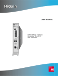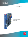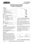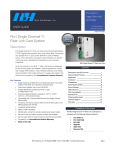
1
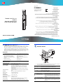
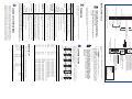
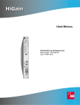
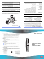
1213778
March 30, 2000
´,-m¶8f¨
REGISTERED FIRM
DNV Certification, Inc.
ISO 9001/TL 9000
Product Catalog: HRU-402-L1,
HRU-402-L3
CLEI: T1L2CW0A, T1L3KLJD
Document: 350-402-100-04, Issue 4
RS-232
DCE
Binational standard, UL-1950/CSA-C22.2 No. 950-95: Safety of Information Technology
Equipment
GR 1089-CORE - Electromagnetic Compatibility and Electrical Safety
RCV
BRG
XMT
DIS
TLOS
LB
RCV
LEV
0
EN
-15
D
S
1
GR 63-CORE - Network Equipment-Building System (NEBS) Requirements
LBK
HRU-402 REMOTE UNITS
LIST 1 (LOCAL AND LINE
POWER)
LIST 3 (LOCAL POWER)
AMI
B8ZS
SF
ESF
LP2
H
D
S
L
LP1
TELEPHONE Co. PROPERTY
Tel: 800.638.0031
Tel: 714.730.3222
Fax: 714.730.2400
Technical Assistance
14402 Franklin Avenue
Tustin, CA 92780-7013
Tel: 714.832.9922
Fax: 714.832.9924
ADC DSL Systems, Inc.
© 2000 ADC DSL Systems, Inc. All rights reserved. Information contained in this document is company
private to ADC DSL Systems, Inc., and shall not be modified, used, copied, reproduced or disclosed in
whole or in part without the written consent of ADC.
Copyright Information
ADC is a registered trademark of ADC Telecommunications, Inc. HiGain is a registered trademark of
ADC DSL Systems, Inc. Other product names mentioned in this installation guide are used for
identification purposes only and may be trademarks or registered trademarks of their respective
companies.
Trademark Information
This equipment has been tested and verified to comply with the applicable sections of the following
safety standards:
Standards Compliance
All wiring external to the products should follow the provisions of the current edition of the National
Electrical Code.
Any changes or modifications made to this device that are not expressly approved by ADC DSL
Systems, Inc. voids the user's warranty.
ALM
Modifications
1
L
HRU-402
HiGain
REM UNIT
Product warranty is determined by your service agreement. Contact your sales representative or
Customer Service for details.
Limited Warranty
This equipment has been tested and found to comply with the limits for a Class A digital device, pursuant
to Part 15 of the FCC Rules. These limits are designed to provide reasonable protection against harmful
interference when the equipment is operated in a commercial environment. This equipment generates,
uses, and can radiate radio frequency energy and, if not installed and used in accordance with the
instruction manual, may cause harmful interference to radio communications. Operation of this
equipment in a residential area is likely to cause harmful interference in which case the user will be
required to correct the interference at his own expense.
QUICK INSTALLATION
FCC Class A Compliance
HiGain
THE HRU-402 LIST 1 AND LIST 3
The HiGain® Remote Units, HRU-402 List 1 or HRU-402 List 3, function as the
remote end of a repeaterless T1 transmission system. An HRU connects to a HiGain
HDSL Line Unit (HLU), creating a HiGain system that provides 1.544 Mbps
transmission on two unconditioned copper pairs over the full Carrier Service Area
(CSA) range. HiGain Doubler Units (HDUs) can also be used to extend the range. The
HRU-402 List 1 supports both local and line powering. The HRU-402 List 3 is only
locally powered and has an expanded input voltage range of -20 to -70 volts.
INSTALLATION
FEATURES
Ultra-low wander
•
Remote provisioning
•
Narrow 200 mechanics
DS1 transmit and receive monitor jacks for
testing
•
Craft port access for maintenance terminal
connection
Lightning and power cross-protection on
HDSL and DS1 interfaces
•
Status Light Emitting Diodes (LEDs) for
Digital Signal Level 1 (DS1) and HDSL
•
1.544 Mbps full-duplex transmission on two
unconditioned copper pairs
Support for up to five spans
•
•
•
•
•
Generic and addressable repeater loopback
activation codes
SPECIFICATIONS
Extended SuperFrame (ESF), SuperFrame (SF) or THRU (unframed)
DS1 Frame Format
Alternate Mark Inversion (AMI), Bipolar with 8-zero Substitution
(B8ZS) or Zero Byte Time Slot Interchange (ZBTSI)
DS1 Line Format
1.544 Mbps ±200 bps
DS1 Line Rate
35 dB at 196 KHz, 135 Ω
Maximum Provisioning Loss
0 dB, -7.5 dB, -15 dB
DS1 Pulse Output
+13 dBm ±0.5 dBm, 135 Ω
HDSL Output
784 kbps 2B1Q full duplex
HDSL Line Code
Narrow 200 mechanics shelf (half-width 400 mechanics)
Mounting
Secondary surge and power cross-protection on all DS1 and HDSL2
ports
Electrical Protection
3.1 W (when connected to HLU-231 List 8x, HLU-319 List 5x, or
HLU-388 List 5x; 4.5W when connected to all other line units.)
Line powered: 5.2 W (List 1, sealing current on); 4.7 W (List 3,
sealing current on)
Locally powered: 4.1 W (List 1, sealing current off); 3.7 W (List 3,
sealing current off)
Power Consumption
5% to 95% non-condensing
Operating Humidity
-40 °F to +149 °F (-40 °C to + 65 °C)
Operating Temperature
1
Switch 1
Switch 2
Set the DS1 RCV LEV and TLOS loopback switches. These switches set the DS1
receive line buildout level toward the Customer Interface (CI).
Sets the DS1 receive level toward the CI according to -15 db.
-15
Default setting. Sets the DS1 receive level toward the CI to 0 db.
0
Disables the TLOS loopback option.
DIS
Default setting. Enables the TLOS loopback option. The TLOS message
displays on the HLU when the HRU is in a logic loopback state caused by a
loss of its T1 input from the CI.
ENA
2
SCURR
LPWR
(List 1 only)
Set the S1 switches (SCURR and LPWR) adjacent to the card-edge connector.
Enables the flow of simplex sealing current towards the
upstream unit. Simplexed sealing current is polarity-sensitive
and will not flow if the HDSL loops adjacent to the HRU are
reversed.
Enable (down position)
Default setting. Disables the flow of simplex sealing current
towards the upstream unit.
Disable (up position)
Configures the HRU-402 to receive power from a local -48V
supply. If local power is not present, the HRU reverts to line
power mode.
Local power (down position)
Default setting. Configures the HRU-402 to receive power
from the upstream line unit over the HDSL pairs.
Line power (up position)
1213778
March 30, 2000
Tel: 800.638.0031
Tel: 714.730.3222
Fax: 714.730.2400
´,-m¶8f¨
REGISTERED FIRM
DNV Certification, Inc.
Technical Assistance
14402 Franklin Avenue
Tustin, CA 92780-7013
Tel: 714.832.9922
Fax: 714.832.9924
Product Catalog: HRU-402-L1,
HRU-402-L3
CLEI: T1L2CW0A, T1L3KLJD
Document: 350-402-100-04, Issue 4
ISO 9001/TL 9000
ADC DSL Systems, Inc.
© 2000 ADC DSL Systems, Inc. All rights reserved. Information contained in this document is company
private to ADC DSL Systems, Inc., and shall not be modified, used, copied, reproduced or disclosed in
whole or in part without the written consent of ADC.
RS-232
DCE
Copyright Information
ADC is a registered trademark of ADC Telecommunications, Inc. HiGain is a registered trademark of
ADC DSL Systems, Inc. Other product names mentioned in this installation guide are used for
identification purposes only and may be trademarks or registered trademarks of their respective
companies.
RCV
BRG
XMT
DIS
TLOS
LB
Trademark Information
Binational standard, UL-1950/CSA-C22.2 No. 950-95: Safety of Information Technology
Equipment
RCV
LEV
GR 1089-CORE - Electromagnetic Compatibility and Electrical Safety
HRU-402 REMOTE UNITS
LIST 1 (LOCAL AND LINE
POWER)
LIST 3 (LOCAL POWER)
EN
0
-15
D
S
1
GR 63-CORE - Network Equipment-Building System (NEBS) Requirements
LBK
This equipment has been tested and verified to comply with the applicable sections of the following
safety standards:
AMI
B8ZS
Standards Compliance
SF
ESF
All wiring external to the products should follow the provisions of the current edition of the National
Electrical Code.
H
D
S
L
Any changes or modifications made to this device that are not expressly approved by ADC DSL
Systems, Inc. voids the user's warranty.
LP2
LP1
TELEPHONE Co. PROPERTY
ALM
Modifications
L
1
HRU-402
HiGain
REM UNIT
Product warranty is determined by your service agreement. Contact your sales representative or
Customer Service for details.
Limited Warranty
This equipment has been tested and found to comply with the limits for a Class A digital device, pursuant
to Part 15 of the FCC Rules. These limits are designed to provide reasonable protection against harmful
interference when the equipment is operated in a commercial environment. This equipment generates,
uses, and can radiate radio frequency energy and, if not installed and used in accordance with the
instruction manual, may cause harmful interference to radio communications. Operation of this
equipment in a residential area is likely to cause harmful interference in which case the user will be
required to correct the interference at his own expense.
QUICK INSTALLATION
FCC Class A Compliance
HiGain
THE HRU-402 LIST 1 AND LIST 3
The HiGain® Remote Units, HRU-402 List 1 or HRU-402 List 3, function as the
remote end of a repeaterless T1 transmission system. An HRU connects to a HiGain
HDSL Line Unit (HLU), creating a HiGain system that provides 1.544 Mbps
transmission on two unconditioned copper pairs over the full Carrier Service Area
(CSA) range. HiGain Doubler Units (HDUs) can also be used to extend the range. The
HRU-402 List 1 supports both local and line powering. The HRU-402 List 3 is only
locally powered and has an expanded input voltage range of -20 to -70 volts.
INSTALLATION
FEATURES
•
1.544 Mbps full-duplex transmission on two
unconditioned copper pairs
•
Generic and addressable repeater loopback
activation codes
•
Status Light Emitting Diodes (LEDs) for
Digital Signal Level 1 (DS1) and HDSL
•
Lightning and power cross-protection on
HDSL and DS1 interfaces
•
Craft port access for maintenance terminal
connection
•
DS1 transmit and receive monitor jacks for
testing
•
Narrow 200 mechanics
•
Remote provisioning
•
Support for up to five spans
•
Ultra-low wander
SPECIFICATIONS
Power Consumption
3.1 W (when connected to HLU-231 List 8x, HLU-319 List 5x, or
HLU-388 List 5x; 4.5W when connected to all other line units.)
Line powered: 5.2 W (List 1, sealing current on); 4.7 W (List 3,
sealing current on)
Locally powered: 4.1 W (List 1, sealing current off); 3.7 W (List 3,
sealing current off)
Electrical Protection
Secondary surge and power cross-protection on all DS1 and HDSL2
ports
Mounting
Narrow 200 mechanics shelf (half-width 400 mechanics)
HDSL Line Code
784 kbps 2B1Q full duplex
HDSL Output
+13 dBm ±0.5 dBm, 135 Ω
DS1 Pulse Output
0 dB, -7.5 dB, -15 dB
Maximum Provisioning Loss
35 dB at 196 KHz, 135 Ω
DS1 Line Rate
1.544 Mbps ±200 bps
DS1 Line Format
Alternate Mark Inversion (AMI), Bipolar with 8-zero Substitution
(B8ZS) or Zero Byte Time Slot Interchange (ZBTSI)
DS1 Frame Format
Extended SuperFrame (ESF), SuperFrame (SF) or THRU (unframed)
1
Switch 1
5% to 95% non-condensing
Switch 2
Operating Humidity
2
SCURR
-40 °F to +149 °F (-40 °C to + 65 °C)
LPWR
(List 1 only)
Operating Temperature
Set the DS1 RCV LEV and TLOS loopback switches. These switches set the DS1
receive line buildout level toward the Customer Interface (CI).
0
Default setting. Sets the DS1 receive level toward the CI to 0 db.
-15
Sets the DS1 receive level toward the CI according to -15 db.
ENA
Default setting. Enables the TLOS loopback option. The TLOS message
displays on the HLU when the HRU is in a logic loopback state caused by a
loss of its T1 input from the CI.
DIS
Disables the TLOS loopback option.
Set the S1 switches (SCURR and LPWR) adjacent to the card-edge connector.
Disable (up position)
Default setting. Disables the flow of simplex sealing current
towards the upstream unit.
Enable (down position)
Enables the flow of simplex sealing current towards the
upstream unit. Simplexed sealing current is polarity-sensitive
and will not flow if the HDSL loops adjacent to the HRU are
reversed.
Line power (up position)
Default setting. Configures the HRU-402 to receive power
from the upstream line unit over the HDSL pairs.
Local power (down position)
Configures the HRU-402 to receive power from a local -48V
supply. If local power is not present, the HRU reverts to line
power mode.
H
D
S
L
D
S
1
L
1
HRU-402
HiGain
REM UNIT
ALM
LP1
LP2
ESF
TELEPHONE Co. PROPERTY
EN
-15
B8ZS
SF
AMI
LBK
RCV
LEV 0
DIS
TLOS
LB
XMT
RCV
BRG
RS-232
DCE
S1 switches (SCURR and LPWR)
Located next to card-edge connector. See step 2 (Installation)
for more information
Loopback control button
Pressing the button for 5 seconds activates
a remote loopback towards the network, called a
Network Remote Loopback (NREM). Any
existing loopback is terminated before NREM
is activated. The unit can be looped down by
either pressing the LPBK control button again
for 5 seconds or by the standard loopdown inband
messages.
DS1 transmit (XMT) and receive (RCV)
bridging jacks
For non-intrusive test access
Craft port provisioning
To access all system maintenance, provisioning
and performance screens, connect a standard
9-pin terminal cable between the serial port on a PC
and the HRU craft port.
Extraction handle
Modem settings:
1200-9600 baud
8 data bits
No parity
1 stop bit
Hardware flow control: OFF
Terminal emulation: VT-100
2
1
Press the SPACEBAR several times to display the Remote Login screen.
NDU1
CREM
NDU2
CDU1
NDU4
CDU3
HDU3
NDU3
CDU2
HDU2
CDU4
CLOC
CLOC
SMJK
NREM
NDU4
NDU3
NDU2
NDU1
NLOC
Loopback
111110
111100
1111100
11000
1110000
1010010
1010001
111000
110000
1111000
Inband Code
Signal from customer is looped back to the customer at HDU4.
Signal from customer is looped back to the customer at HDU3.
Signal from customer is looped back to the customer at HDU2.
Signal from customer is looped back to the customer at HDU1.
Signal from customer is looped back to the customer at the HRU.
DSX-1 signal is looped back to the network at the HRU SmartJack
module.
DSX-1 signal is looped back to the network at the HRU.
DSX-1 signal is looped back to the network at HDU4.
DSX-1 signal is looped back to the network at HDU3.
DSX-1 signal is looped back to the network at HDU2.
DSX-1 signal is looped back to the network at HDU1.
DSX-1 signal is looped back to the network at the HLU.
Description
NREM
SMJK
TLOS
CDU1
1011001
Signal from customer is looped back to the customer at the HLU.
HDU4
CDU2
1011010
Deactivates any of the above loopbacks.
HDU1
CDU3
1111110
HRU
Customer
Premises
CDU4
11100
GNLB Loopback Commands
CREM
HLU-200
HLU-388 List 5x
HLU-319 List 5x
HLU-231 List 8x
Line Units
HDU-451 List 4 or 4B
HDU-439 List 1 or 1B
HDU-437
HDU-409
HDU-407
HDU-404
Doublers
400 mechanics shelves
200 mechanics shelves
HRE-427
HRE-425
HRE-422
HRE-420
Indoor Enclosures
HRE-454
HRE-450
Outdoor Enclosures
The HRU-402 List 1 and List 3 are compatible with the following ADC products:
COMPATIBILITY
Loopdown
HLU
Network
NLOC
Initiate loopback testing from the maintenance terminal menus or by using inband codes.
The inband codes shown below can be sent by a test set. For more information, refer to the
technical practice for the HLU line unit.
LOOPBACK TESTING
For more detailed information about the Maintenance Terminal
screens, provisioning, and loopback mode testing, download the
appropriate line unit technical practice from the ADC website at
www.adc.com. To order a hard copy, please contact your sales
representative.
Press the ENTER key to view the HiGain Maintenance Terminal Screen. The Remote
Terminal Main Menu items are replications of the line unit screens. Depending on the
HLU attached to the HRU-402, remote provisioning may be available. Refer to the
HLU technical practice for details.
To log on and access the Remote Terminal Main Menu screens using a maintenance
terminal:
55 DS1 Tip
53
XMT
List number
51
49 DS1 Ring
Alarm LED
47 HDSL2 Ring1
45
HDSL LEDs
43
41 HDSL2 Tip 1
DS1 framing LEDs
39
37 Factory Use Only
DS1 code LEDs
35 ( - )
33
Loopback LED
31
29
-48 Vdc Local Power (List 1)
27 Chassis Ground* -20 Vdc to -70 Vdc Local Power (List 3)
25
DS1 RSV LEV
and TLOS loopback
23
switches
21
19
(+)
17 Circuit Ground
15 DS1 Ring1
13 HDSL1 Ring
11
RCV
9
CLEI/ECI Bar code label
7 HDSL1 Tip
5 DS1 Tip1
3
Configuration number label
1 Chassis Ground*
(inside handle)
Card-edge Connector
56
54
52
50
48
46
44
42
Protection Switch Control 40
Factory Use Only 38
36
34
32
30
28
26
24
22
Factory Use Only 20
18
16
14
Protection Switch Power 12
10
8
6
4
2
*Chassis Ground may be tied to earth ground per local practice.
Note: Active pins are highlighted in black.
Align the HRU with the enclosure slot guides, then push the unit in until it is properly
seated in the backplane card-edge connector.
Disable the SCURR switch if you are using an HDU-451 List 1,
2, 3, or 3B.
Enable the SCURR switch if you are using the following
doublers: HDU-404, HDU-407, HDU-409, HDU-437, HDU-439
List 1 or 1B, HDU-451 List 4 or 4B.
INSTALLATION CONTINUED
3
VERIFICATION
Once the HRU is installed, verify that it is operating properly by monitoring the Status
LEDs on the front panel.
Indicates
Status LED Descriptions
LED Status
Indicates the HRU is in an Armed state.
Indicates Customer Local (CLOC) loopback state.
Indicates that the DS1 line code option is set to Bipolar with 8-Zero Substitution
(B8ZS). The LED blinks once per second when a string of excessive zeros is
detected.
Indicates that the user DS1 line code option is set to Alternate Mark Inversion
(AMI). This LED blinks once per second when a Bipolar Violation (BPV) is
detected.
Shows loopback states to and from the network and to and from the Customer
Interface (CI).
Indicates Network Remote (NREM), SmartJack (SMJK), or Transmit Loss of
Signal (TLOS) loopback.
Indicates DS1 code options. If DS1 signals are not detected, the B8ZS and AMI
LEDs will not light.
Indicates Extended Super Frame (ESF). The LED blinks once per second when a
frame error occurs.
Indicates Super Frame (SF). The LED blinks once per second when a frame error
occurs.
Indicates unframed or no signal.
Indicates framing patterns. If DS1 signals are not detected, the ESF and SF LEDs
will not light.
Indicates no activity on the HDSL loop.
Indicates a Cyclical Redundancy Check (CRC) error on the HDSL loop.
Indicates a margin alarm condition on the HDSL loop.
Indicates the HDSL loop is trying to acquire sync.
Indicates HDSL loop is in sync.
Displays HDSL Loop 1 (LP1) and Loop 2 (LP2) conditions.
Indicates a Loss of Signal (LOS) condition at the T1 input of the HRU.
Indicates a LOS condition at the T1 input of the line unit.
Shows alarm states for remote and local Loss of Signal (LOS).
Solid red
Blinking
Alarm (ALM) LED
HDSL LED
Solid green
Blinking once
per second
Blinking 4 times
per second
Blinking 10 times
per second
OFF
DS1 Framing (FRM)
LEDs (ESF and SF) (a)
ESF LED = Solid green
SF LED = Solid green
OFF
DS1 Code LEDs (B8ZS
and AMI) (a) (b)
B8ZS LED = Solid green
AMI LED = Solid green
Loopback (LPBK) LED
Solid yellow
Blinking once
per second
Blinking 4 times per
second
(a) If DS1 signals are not detected the ESF, SF, B8ZS and AMI LEDs do not light.
(b) Auto option indicates when the DS1 code is being detected as AMI or B8ZS. This option is not available
with HLU-231 List 8D and List 8E, HLU-319 List 5D and List 5E, or HLU-388 List 5D and List 5E.
LOGGING ON TO THE MAIN MENU
The HRU-402 List 1 and List 3 support local and remote logon through a maintenance
terminal (VT-100 or a PC running VT-100 terminal-emulation software) connected to the
craft port on the front panel. Remote login creates menus and screens for the HRU that are
identical to those viewed at the HLU. Once logged on, you can access the Remote Terminal
Main Menu screens to view system settings, initiate loopbacks, and provision the circuit.
Card-edge Connector
55 DS1 Tip
53
XMT
List number
51
49 DS1 Ring
Alarm LED
47 HDSL2 Ring1
45
HDSL LEDs
43
41 HDSL2 Tip 1
DS1 framing LEDs
39
37 Factory Use Only
DS1 code LEDs
35 ( - )
33
Loopback LED
31
29
-48 Vdc Local Power (List 1)
27 Chassis Ground* -20 Vdc to -70 Vdc Local Power (List 3)
25
DS1 RSV LEV
and TLOS loopback
23
switches
21
19
(+)
17 Circuit Ground
15 DS1 Ring1
13 HDSL1 Ring
11
RCV
9
CLEI/ECI Bar code label
7 HDSL1 Tip
5 DS1 Tip1
3
Configuration number label
1 Chassis Ground*
(inside handle)
32
30
28
26
24
22
Factory Use Only 20
18
16
14
Protection Switch Power 12
10
8
6
4
2
HRU-402
HiGain
REM UNIT
L
1
ALM
LP1
H
D
S
L
S1 switches (SCURR and LPWR)
Located next to card-edge connector. See step 2 (Installation)
for more information
TELEPHONE Co. PROPERTY
56
54
52
50
48
46
44
42
Protection Switch Control 40
Factory Use Only 38
36
34
LP2
ESF
SF
B8ZS
Loopback control button
Pressing the button for 5 seconds activates
a remote loopback towards the network, called a
Network Remote Loopback (NREM). Any
existing loopback is terminated before NREM
is activated. The unit can be looped down by
either pressing the LPBK control button again
for 5 seconds or by the standard loopdown inband
messages.
AMI
LBK
D
S
1
RCV
LEV 0
-15
DIS
TLOS
LB
EN
DS1 transmit (XMT) and receive (RCV)
bridging jacks
XMT
BRG
For non-intrusive test access
RCV
RS-232
DCE
Craft port provisioning
To access all system maintenance, provisioning
and performance screens, connect a standard
9-pin terminal cable between the serial port on a PC
and the HRU craft port.
Modem settings:
1200-9600 baud
8 data bits
No parity
1 stop bit
Hardware flow control: OFF
Terminal emulation: VT-100
Extraction handle
*Chassis Ground may be tied to earth ground per local practice.
Note: Active pins are highlighted in black.
INSTALLATION CONTINUED
Enable the SCURR switch if you are using the following
doublers: HDU-404, HDU-407, HDU-409, HDU-437, HDU-439
List 1 or 1B, HDU-451 List 4 or 4B.
To log on and access the Remote Terminal Main Menu screens using a maintenance
terminal:
1
Press the SPACEBAR several times to display the Remote Login screen.
2
Press the ENTER key to view the HiGain Maintenance Terminal Screen. The Remote
Terminal Main Menu items are replications of the line unit screens. Depending on the
HLU attached to the HRU-402, remote provisioning may be available. Refer to the
HLU technical practice for details.
Disable the SCURR switch if you are using an HDU-451 List 1,
2, 3, or 3B.
3
For more detailed information about the Maintenance Terminal
screens, provisioning, and loopback mode testing, download the
appropriate line unit technical practice from the ADC website at
www.adc.com. To order a hard copy, please contact your sales
representative.
Align the HRU with the enclosure slot guides, then push the unit in until it is properly
seated in the backplane card-edge connector.
VERIFICATION
LOOPBACK TESTING
Once the HRU is installed, verify that it is operating properly by monitoring the Status
LEDs on the front panel.
Status LED Descriptions
LED Status
Initiate loopback testing from the maintenance terminal menus or by using inband codes.
The inband codes shown below can be sent by a test set. For more information, refer to the
technical practice for the HLU line unit.
Indicates
Alarm (ALM) LED
Shows alarm states for remote and local Loss of Signal (LOS).
Solid red
Blinking
HDSL LED
Indicates a Loss of Signal (LOS) condition at the T1 input of the HRU.
Indicates a LOS condition at the T1 input of the line unit.
CREM
NLOC
CDU1
NDU1
CDU3
CDU2
NDU2
NDU3
CDU4
NDU4
NREM
SMJK
TLOS
CLOC
Displays HDSL Loop 1 (LP1) and Loop 2 (LP2) conditions.
Solid green
Blinking once
per second
Blinking 4 times
per second
Blinking 10 times
per second
OFF
DS1 Framing (FRM)
LEDs (ESF and SF) (a)
ESF LED = Solid green
SF LED = Solid green
OFF
DS1 Code LEDs (B8ZS
and AMI) (a) (b)
B8ZS LED = Solid green
AMI LED = Solid green
Loopback (LPBK) LED
Solid yellow
Blinking once
per second
Blinking 4 times per
second
Indicates HDSL loop is in sync.
HLU
Network
HDU1
HDU2
HDU3
HDU4
HRU
Customer
Premises
Indicates the HDSL loop is trying to acquire sync.
GNLB Loopback Commands
Indicates a margin alarm condition on the HDSL loop.
Indicates a Cyclical Redundancy Check (CRC) error on the HDSL loop.
Indicates no activity on the HDSL loop.
Indicates framing patterns. If DS1 signals are not detected, the ESF and SF LEDs
will not light.
Indicates Extended Super Frame (ESF). The LED blinks once per second when a
frame error occurs.
Indicates Super Frame (SF). The LED blinks once per second when a frame error
occurs.
Indicates unframed or no signal.
Indicates DS1 code options. If DS1 signals are not detected, the B8ZS and AMI
LEDs will not light.
Indicates that the DS1 line code option is set to Bipolar with 8-Zero Substitution
(B8ZS). The LED blinks once per second when a string of excessive zeros is
detected.
Indicates that the user DS1 line code option is set to Alternate Mark Inversion
(AMI). This LED blinks once per second when a Bipolar Violation (BPV) is
detected.
Shows loopback states to and from the network and to and from the Customer
Interface (CI).
Indicates Network Remote (NREM), SmartJack (SMJK), or Transmit Loss of
Signal (TLOS) loopback.
Indicates Customer Local (CLOC) loopback state.
Loopback
Inband Code
Description
NLOC
1111000
DSX-1 signal is looped back to the network at the HLU.
NDU1
110000
DSX-1 signal is looped back to the network at HDU1.
NDU2
111000
DSX-1 signal is looped back to the network at HDU2.
NDU3
1010001
DSX-1 signal is looped back to the network at HDU3.
NDU4
1010010
DSX-1 signal is looped back to the network at HDU4.
NREM
1110000
DSX-1 signal is looped back to the network at the HRU.
SMJK
11000
DSX-1 signal is looped back to the network at the HRU SmartJack
module.
CLOC
1111100
Signal from customer is looped back to the customer at the HRU.
CDU1
111100
Signal from customer is looped back to the customer at HDU1.
CDU2
111110
Signal from customer is looped back to the customer at HDU2.
CDU3
1011001
Signal from customer is looped back to the customer at HDU3.
CDU4
1011010
Signal from customer is looped back to the customer at HDU4.
CREM
1111110
Signal from customer is looped back to the customer at the HLU.
Loopdown
11100
Deactivates any of the above loopbacks.
COMPATIBILITY
The HRU-402 List 1 and List 3 are compatible with the following ADC products:
Indicates the HRU is in an Armed state.
(a) If DS1 signals are not detected the ESF, SF, B8ZS and AMI LEDs do not light.
(b) Auto option indicates when the DS1 code is being detected as AMI or B8ZS. This option is not available
with HLU-231 List 8D and List 8E, HLU-319 List 5D and List 5E, or HLU-388 List 5D and List 5E.
LOGGING ON TO THE MAIN MENU
The HRU-402 List 1 and List 3 support local and remote logon through a maintenance
terminal (VT-100 or a PC running VT-100 terminal-emulation software) connected to the
craft port on the front panel. Remote login creates menus and screens for the HRU that are
identical to those viewed at the HLU. Once logged on, you can access the Remote Terminal
Main Menu screens to view system settings, initiate loopbacks, and provision the circuit.
Line Units
Doublers
Indoor Enclosures
Outdoor Enclosures
HLU-231 List 8x
HDU-404
HRE-420
HRE-450
HLU-319 List 5x
HDU-407
HRE-422
HRE-454
HLU-388 List 5x
HDU-409
HRE-425
HLU-200
HDU-437
HRE-427
HDU-439 List 1 or 1B
200 mechanics shelves
HDU-451 List 4 or 4B
400 mechanics shelves
1213778
March 30, 2000
´,-m¶8f¨
REGISTERED FIRM
DNV Certification, Inc.
ISO 9001/TL 9000
Product Catalog: HRU-402-L1,
HRU-402-L3
CLEI: T1L2CW0A, T1L3KLJD
Document: 350-402-100-04, Issue 4
RS-232
DCE
Binational standard, UL-1950/CSA-C22.2 No. 950-95: Safety of Information Technology
Equipment
GR 1089-CORE - Electromagnetic Compatibility and Electrical Safety
RCV
BRG
XMT
DIS
TLOS
LB
RCV
LEV
0
EN
-15
D
S
1
GR 63-CORE - Network Equipment-Building System (NEBS) Requirements
LBK
HRU-402 REMOTE UNITS
LIST 1 (LOCAL AND LINE
POWER)
LIST 3 (LOCAL POWER)
AMI
B8ZS
SF
ESF
LP2
H
D
S
L
LP1
TELEPHONE Co. PROPERTY
Tel: 800.638.0031
Tel: 714.730.3222
Fax: 714.730.2400
Technical Assistance
14402 Franklin Avenue
Tustin, CA 92780-7013
Tel: 714.832.9922
Fax: 714.832.9924
ADC DSL Systems, Inc.
© 2000 ADC DSL Systems, Inc. All rights reserved. Information contained in this document is company
private to ADC DSL Systems, Inc., and shall not be modified, used, copied, reproduced or disclosed in
whole or in part without the written consent of ADC.
Copyright Information
ADC is a registered trademark of ADC Telecommunications, Inc. HiGain is a registered trademark of
ADC DSL Systems, Inc. Other product names mentioned in this installation guide are used for
identification purposes only and may be trademarks or registered trademarks of their respective
companies.
Trademark Information
This equipment has been tested and verified to comply with the applicable sections of the following
safety standards:
Standards Compliance
All wiring external to the products should follow the provisions of the current edition of the National
Electrical Code.
Any changes or modifications made to this device that are not expressly approved by ADC DSL
Systems, Inc. voids the user's warranty.
ALM
Modifications
1
L
HRU-402
HiGain
REM UNIT
Product warranty is determined by your service agreement. Contact your sales representative or
Customer Service for details.
Limited Warranty
This equipment has been tested and found to comply with the limits for a Class A digital device, pursuant
to Part 15 of the FCC Rules. These limits are designed to provide reasonable protection against harmful
interference when the equipment is operated in a commercial environment. This equipment generates,
uses, and can radiate radio frequency energy and, if not installed and used in accordance with the
instruction manual, may cause harmful interference to radio communications. Operation of this
equipment in a residential area is likely to cause harmful interference in which case the user will be
required to correct the interference at his own expense.
QUICK INSTALLATION
FCC Class A Compliance
HiGain
THE HRU-402 LIST 1 AND LIST 3
The HiGain® Remote Units, HRU-402 List 1 or HRU-402 List 3, function as the
remote end of a repeaterless T1 transmission system. An HRU connects to a HiGain
HDSL Line Unit (HLU), creating a HiGain system that provides 1.544 Mbps
transmission on two unconditioned copper pairs over the full Carrier Service Area
(CSA) range. HiGain Doubler Units (HDUs) can also be used to extend the range. The
HRU-402 List 1 supports both local and line powering. The HRU-402 List 3 is only
locally powered and has an expanded input voltage range of -20 to -70 volts.
INSTALLATION
FEATURES
Ultra-low wander
•
Remote provisioning
•
Narrow 200 mechanics
DS1 transmit and receive monitor jacks for
testing
•
Craft port access for maintenance terminal
connection
Lightning and power cross-protection on
HDSL and DS1 interfaces
•
Status Light Emitting Diodes (LEDs) for
Digital Signal Level 1 (DS1) and HDSL
•
1.544 Mbps full-duplex transmission on two
unconditioned copper pairs
Support for up to five spans
•
•
•
•
•
Generic and addressable repeater loopback
activation codes
SPECIFICATIONS
Extended SuperFrame (ESF), SuperFrame (SF) or THRU (unframed)
DS1 Frame Format
Alternate Mark Inversion (AMI), Bipolar with 8-zero Substitution
(B8ZS) or Zero Byte Time Slot Interchange (ZBTSI)
DS1 Line Format
1.544 Mbps ±200 bps
DS1 Line Rate
35 dB at 196 KHz, 135 Ω
Maximum Provisioning Loss
0 dB, -7.5 dB, -15 dB
DS1 Pulse Output
+13 dBm ±0.5 dBm, 135 Ω
HDSL Output
784 kbps 2B1Q full duplex
HDSL Line Code
Narrow 200 mechanics shelf (half-width 400 mechanics)
Mounting
Secondary surge and power cross-protection on all DS1 and HDSL2
ports
Electrical Protection
3.1 W (when connected to HLU-231 List 8x, HLU-319 List 5x, or
HLU-388 List 5x; 4.5W when connected to all other line units.)
Line powered: 5.2 W (List 1, sealing current on); 4.7 W (List 3,
sealing current on)
Locally powered: 4.1 W (List 1, sealing current off); 3.7 W (List 3,
sealing current off)
Power Consumption
5% to 95% non-condensing
Operating Humidity
-40 °F to +149 °F (-40 °C to + 65 °C)
Operating Temperature
1
Switch 1
Switch 2
Set the DS1 RCV LEV and TLOS loopback switches. These switches set the DS1
receive line buildout level toward the Customer Interface (CI).
Sets the DS1 receive level toward the CI according to -15 db.
-15
Default setting. Sets the DS1 receive level toward the CI to 0 db.
0
Disables the TLOS loopback option.
DIS
Default setting. Enables the TLOS loopback option. The TLOS message
displays on the HLU when the HRU is in a logic loopback state caused by a
loss of its T1 input from the CI.
ENA
2
SCURR
LPWR
(List 1 only)
Set the S1 switches (SCURR and LPWR) adjacent to the card-edge connector.
Enables the flow of simplex sealing current towards the
upstream unit. Simplexed sealing current is polarity-sensitive
and will not flow if the HDSL loops adjacent to the HRU are
reversed.
Enable (down position)
Default setting. Disables the flow of simplex sealing current
towards the upstream unit.
Disable (up position)
Configures the HRU-402 to receive power from a local -48V
supply. If local power is not present, the HRU reverts to line
power mode.
Local power (down position)
Default setting. Configures the HRU-402 to receive power
from the upstream line unit over the HDSL pairs.
Line power (up position)