1
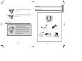
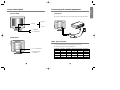
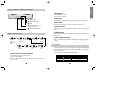
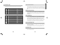
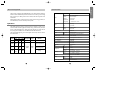
*1¿
97.3.29 10:25 AM ˘ ` 1
Contents
2
UserÕs Guide
How to get the most enjoyment with monitor
2
¥ Features
3
¥ General Safety precautions
4
¥ Maintenance
Installation
5
¥ Packing List
6
¥ Control description
7
¥ Connecting with external equipment
7
¥ Video input terminal
8
On Screen Display(OSD) Control Button
8
OSD Control Procedure
9
Using Hot key
10
On Screen Display Setting
11
Preset Mode chart
13
Microcontroller features
14
Power management
15
Specifications
English
5
*1¿
97.3.29 10:25 AM ˘ ` 2
This is a 15.0Ócolor LCD monitor to display signals from PC or Video
equipment.
This manual has been prepared to assist you in becoming familiar with your
new display monitor.
Features
¥15 .0Ó viewable XGA (1024 X 768) resolution LCD module
¥262,144 Color Display
¥Brightness (250cd/m2)
¥Viewing angle (U/D: 55°/60°, R/L : 70°/70°)
¥DPMS (Display Power Management Signaling)
¥OSD (On screen Display) controls, Multi Language OSD Menu
¥Implement the DDC 1/2B features.
DDC 1/2B uses a formerly unconnected signal pins in the 15 -pin VGA
connector.
The system will perform ÒPlug&PlayÓ feature if both monitor and host
systems support DDC 1/2B protocol.
Note
Some computer systems are not compatible
with the DDC standard.
If your monitor is displaying a wrong
resolution, please check your computer
system including a DDC compatible video
card and contact HANSOL Service Center.
2
General Safety precautions
This Monitor has been engineered and manufactured to assure your safety, and
you can prevent your safety from serious electrical shock and other hazards by
keeping in the following attentions.
1
Do not place heavy, wet or magnetic on the
monitor or the power cord. Never cover the
ventilation openings with any material and
never touch them with metallic of
inflammable materials.
2
Avoid operating the monitor in the place
extremely heated, humid or affected by dust.
Temperature : 0 ~ 40°C
Humidity : 30 ~ 80RH
3
Be sure to turn the monitor off before
plugging the power cord into the socket of
power source.
Make sure that the power cord and the other
cords are securely and rightly connected.
4
Overloaded AC outlets and extension cords
are dangerous. So are frayed power cords and
broken plugs. They may result in a shock or
fire hazard. Call your service technician for
replacement.
3
English
How to get the most enjoyment with monitor
*1¿
97.3.29 10:25 AM ˘ ` 4
5
Do not use the sharp tool such as pin or
pencil to avoid the scratch on the LCD
surface.
6
Do not use the solvent such as benzene to
clean the monitor. It will damage to LCD
surface.
English
Installation
Packing List
Maintenance
P LCD 15.0Ó MONITOR
Do not open the monitor. There are no user
serviceable components inside.
There is dangerous high voltage inside, even
when power is off. If the display monitor does
not operate properly, remove the power cord
from the wall outlet, and contact your dealer.
Careless use and un-professional maintenance are able to cause serious electrical
shock and other hazards.
P VGA CABLE
P USERÕS GUIDE
4
P POWER CORD
P AC / DC ADAPTOR PMONITOR INSTALLATION
PROGRAM DISKETTE
5
*1¿
97.3.29 10:25 AM ˘ ` 6
■
Connecting with external equipment
Front View
■
English
Control description
Cautions
Be sure to turn off the power of your computer before connecting the Monitor.
P OSD KEY
M (Menu)
o
p
S (Select)
P POWER KEY
P LED INDICATOR
■
Rear View
Video input terminal
A 15 pin D-sub connector is used as the input signal connector.
Pin and input signs are shown in the table below
P 12V DC POWER JACK
P VGA(15PIN D-SUB)
CONNECTOR
6
Pin number Signal name Pin number Signal name Pin number
2
3
Red
Green
1
5
6
N.C
GND
4
8
9
GREEN-GND
BLUE-GND
7
11
12
Logic-GND
N.C
10
14
15
H-sync
V-sync
13
7
Signal name
Blue
RED-GND
+5V
SDA (DDC)
SCL (DDC)
*1¿
97.3.29 10:26 AM ˘ ` 8
■
English
On Screen Display (OSD) Control Button
Exit Menu
Press the MENU key to exit.
The power LED is lit green.
■
P 5 POWER ON / OFF
P 4 POWER LED INDICATOR
The OSD images are disappeared automatically after few seconds inactivity.
■
P 3 SELECT
■
■
OSD Control Procedure
3
Move the
MENU Icon
Select the MENU
1
■
DPMS mode
The LED indicates different status when this unit operates in different power
saving modes.
2
End of
adjustment
Normal mode
When video signal is working with normal display condition, power LED is lit
Green.
P 1 ENABLE THE OSD MENU/ EXIT
Start press the
MENU key to
enable the OSD
MENU
Auto save
The monitor automatically saves the new setting while OSD is exit.
P 2 SELECT THE FUNCTION(q ,Q)
ADJUST THE VALUE(+ ,-)
1
Auto exit
2
Move the Bar
1
Exit
1
End of adjust the
value
3
Select the
Function
2
adjust the
value
Main menu & control selection
Press the MENU key to access the main menu.
The power LED is blinking.
Please the select MENU Icon the control function you wish to adjust by
the o or pkey.
8
■
Not Supported Video
When unsuitable signal is detected, the OSD displays ÒNot Supported VideoÓ
message.
Using Hotkey
Frequent adjustments such as AUTOMATIC ADJUSTMENT, BRIGHTNESS
and CONTRAST can be done in easy without using MENU key which display
all of the control menu.
Following table describes the allocation of the HotKey
OSD Button
Function
Automatic Adjustment
Contrast
Brightness
9
*1¿
97.3.29 10:26 AM ˘ ` 10
Preset Mode chart
English
On Screen Display Setting
Timing Charts
Auto Adjustment
Geometry
Automatically adjust the vertical position, Horizontal
position, Horizontal size and Phase
Color Balance
Automatically adjustment the contrast of the screen
Horizontal Position
Adjust the horizontal position
Vertical Position
Adjust the vertical position
Horizontal Size
Adjust the width of the screenÕs image
Phase
Adjust the noise of the screenÕs image
Brightness
Adjust the intensity of the screen
Contrast
Adjust the contrast of the screen
Color
Support video timings this monitor shall be capable of display following video
timing chart.
Video
Sync
Front Porch(T5)
Active(T4)
Back Porch(T3)
Sync Width(T2)
Period(T1)
Input timing limits
Temperature
Adjust the color temperature of the screenÕs image
Red
Control the intensity of the Red colour of the screenÕs image
Green
Control the intensity of the Green colour of the screenÕs image
Blue
Control the intensity of the Blue colour of the screenÕs image
OSD Language
H-sync pulse width 1.0us§ZSync Pulse Width§Z8.0us
V-sync pulse width 0.04ms§ZSync Pulse Width§Z0.5ms
Note
Language
English
English
French
French
German
German
Italian
Italian
Spanish
Spanish
If the width of Sync pulse is out of input timing
range, monitor may be able to operate abnormal.
Be sure to check the sync pulse width of input
timing.
Input level limits
Advanced
Factory Preset
Load the factory preset mode
Sharpness
Adjust the sharpness of the screenÕs image
DOS/GFX
Select resolution 720 X 400 or 640X 400 mode
OSD H. Position
Adjust the horizontal position of the OSD
OSD V. Position
Adjust the vertical position of the OSD
Cancel
Exit Without Saving
10
Low level : 0.4V max
High level : 2.4V min
Note
For better quality of display image, use the timing
and polarity shown in the preset mode table.
Please see your video card userÕs guide to
ensure compatibility.
11
*1¿
97.3.29 10:26 AM ˘ ` 12
The timing shown in the following table will be factory preset for display.
Horizontal
Frequency
Period(T1)
Sync Width(T2)
Back Porch(T3)
Active(T4)
Front Porch(T5)
Pixel
KH2
µs
µs
µs
µs
µs
640
31.469
31.778
2.542
3.178
25.422
0.635
720
31.469
31.778
3.813
1.907
25.422
0.636
640
31.469
31.778
3.813
1.907
25.422
0.636
640
37.500
26.667
2.032
3.810
20.317
0.508
640
37.861
26.413
1.270
3.810
20.317
0.762
640
35.000
28.571
2.116
3.175
21.164
2.116
800
35.156
28.444
2.000
3.555
22.222
0.667
800
37.879
26.400
3.200
2.200
20.000
1.000
800
46.875
21.333
1.616
3.232
16.162
0.323
800
48.077
20.800
2.400
1.280
16.000
1.120
1024
48.363
20.677
2.092
2.462
15.754
0.369
1024
56.476
17.707
1.813
1.920
13.653
0.320
1024
60.023
16.660
1.219
2.235
13.003
0.203
1024
57.928
17.247
1.662
2.078
13.299
0.208
Line
H2
ms
ms
ms
ms
ms
Y/N
H
Sync Polarity
V
350
70.087
14.268
0.095
1.905
11.136
1.145
N
P
N
400
70.087
14.268
0.064
1.080
12.711
0.413
N
N
P
480
59.940
16.683
0.064
1.048
15.253
0.318
N
-
480
75.000
13.333
0.080
0.427
12.800
0.027
N
-
480
72.809
13.735
0.079
0.528
12.678
0.238
N
-
480
66.667
15.000
0.086
1.110
13.714
0.086
N
-
600
56.250
17.778
0.057
0.626
17.067
0.028
N
-
600
60.317
16.579
0.106
0.607
15.840
0.026
N
-
600
75.000
13.333
0.064
0.448
12.800
0.021
N
-
600
72.188
13.853
0.125
0.478
12.480
0.021
N
-
768
60.004
16.666
0.124
0.600
15.880
0.062
N
-
768
70.069
14.272
0.106
0.513
13.599
0.053
N
-
768
75.029
13.328
0.050
0.466
12.795
0.017
N
-
768
72.117
13.866
0.121
0.448
13.246
0.086
N
-
Vertical
Frequency
Period(T1)
Sync Width(T2)
Back Porch(T3)
Active(T4)
Front Porch(T5)
Interlaced
The microcontroller automatically detects the video board installed in your
system. When you turn on the monitor, the Micro controller first checks the
display mode memory stored in the user setting area and the factory presetting
area.
Display modes memory
The microcontroller has memory capacity to store 24 different display modes
including timing formats and display settings. This memory capacity is
divided into two parts. One is the user setting area, the other is the factory
presetting area.
User setting area
The user can add nonstandard modes. If you adjust display Image, the image
is saved automatically. Then the microcontroller always detects and displays
the last mode stored in the user setting area when the monitor is turned on.
The user setting area maintains the last 6 display modes set by the user in its
memory. When the user setting area is full(6 modes are registered), if new
nonstandard timing is registered, the oldest timing settings will be deleted.
Factory presetting area
There are 14 display modes stored in this area. These display modes are preset
at the factory and include most of the display modes currently available(see
Timing Chart of this manual).
You can also retrieve the factory preset mode by selecting the RECALL menu.
Automatic save
The monitor automatically saves the setting value after certain times
(20 sec) of adjusting OSD menu.
12
13
English
Microcontroller features
Preset Mode Table
*1¿
97.3.29 10:26 AM ˘ ` 14
Specifications
This monitor equipped with DPMS(Display Power Management Signaling)
function which automatically leads the monitor to the state of power saving
that consumes just a little power less than 5Watt, when the computer is left
unattended.
Although the monitor can be left in power-saving mode for longer periods, we
recommend that you turn it off after your daily work
Operation
The DPMS function requires support from the computer system of any
software DPMS function applied, currently being used. If the keyboard(or
mouse) is left unattended for a certain period, the program or system will set
the sync signals to DPMS modes. The DPMS function has three status.
The recommended signals, power consumption and recovery times are shown
in the table below.
Status
On
Standby
Signal
Power
Recovery
Hsync Vsync Video Consumption Time
Pulse Pulse Active 30Watt (Max)
Off
Alternating
Green/Orange (0.5sec)
No
Pulse Pulse Blank
No
Suspend Pulse
Blank
Pulse
LED
Indicator
Green
Less than
5 Watt
No Blank
No
Pulse
Pulse
Within
2sec
Alternating
Green/Orange (1sec)
Orange
14
Type
TFT Color
Size
Dot Pitch
Brightness
Response Time
Viewing Angle
15.0Ó viewable, diagonal
0.297 X 0.297(mm)
250 cd/m2(Typ)
40msec Max.
U/ D : 55°/60°, R/ L: 70°/70°
Input
Signal
Type
RGB Analog
15pin D - sub
Sync
H - Freq
V - Freq
31.5KHz ~ 60KHz
56Hz - 75Hz
LCD
Video Band Width
Display
Active Area
Color
Resolution(max)
User Controls & OSD Controls
Power Management
Power Consumption
Power
Plug & Play
Tilt
U/D
Operating
Temperature
Storage
Operating
Humidity
Storage
Approval
Unit
Weight
Carton
Dimension(W X H X Dmm)
80MHz Max
304.1(H) X 228.1(V)
262.144(Normal), 16.777.216(Expansion)
1024 X 768@75Hz
Contrast, Brightness, H/V Position etc.
VESA DPMS
30Watt(Max)
DC 12V 2.5A
VESA DDC1/2B
35°/ 5°
0 to 40°C
- 10 to 50°C
30% to 80%(Non - condensing)
5% to 90%(Non - condensing)
TCO99, FCC, CE, UL, MPRII
4.35Kg
6.25Kg
393 X 190 X 393 mm
15
English
Power management