1
P Chassis
for Motorhomes
General Information
for Alignment
http://users.sisna.com/cebula/P-Chassis-AlignmentProcess.pdf
Version 1.4 –December 2, 2006
Introduction
The intent of this document is to provide both reference information and guidance to get
the Chevrolet P Chassis to perform as it was designed to perform and maybe even make a
few improvements. I've tried to highlight these in bold.
A majority of the information is taken from the 1995 and 1997 “Chevrolet Motor Home Chassis
Service Guide” for the P Chassis. However, the information has been presented in what is felt
to be a logical sequence to accomplish that most elusive item for this chassis – good
handling.
Age is the common enemy of the chassis. It has been around a long time and many of the
older motorhomes on this chassis are showing signs of age. The idea here is to simply get
appropriate repairs done to bring the chassis back to good condition and then figure out the
correct specifications for alignment.
Along the way, you have probably encountered your share of not-so-competent mechanics
and/or alignment shops. Matter of fact, many alignment shops simply don't know how to
deal with this motorhome version of the P Chassis and wind up treating it like a truck.
We will show you that simply telling the alignment shop that it's a “P30 Chassis” will almost
guarantee you an incorrect alignment. Your Class A motorhome is NOT built on a “P30
Chassis”. The correct general term is a “Motorhome P Chassis”. The P Chassis was also
used for what is referred to as a Commercial (Forward Control) truck. The same chassis
series has been used for G10, G20, G30, P20, P30, and Motorhomes under a '32 - 52'
designation. What's more, the alignment specs are different for the motorhome chassis
because they were made slightly different.
If you decide to do some of the repair work yourself, such as replacing bushings, remember
that you can generally 'rent' specialty front end tools from your local parts store at a cost of
$0.00 when you buy the parts from them. A deposit is all that is generally required. You can
probably get some good instructions on safely using the tools too.
Chevrolet had 7 model numbers for the Motor Home P Chassis, only the ones with '-52'
were destined for Class A motorhomes. Class C motorhomes were also built on some of
the Commercial truck chassis. Those Class C models would rightfully be referred to as using
the 'P-30' Chassis and would use the alignment specs for the truck version.
P30832
P31132 - 52
P31432 - 52
P31832 - 52
P31932 - 52
P32032 - 52
P32132 - 52
125” wheelbase
137” wheelbase
159” wheelbase
178” wheelbase
190” wheelbase (Start-up production in 1991) (19.5” wheels)
208” wheelbase (Start-up production in 1988) (19.5” wheels)
228” wheelbase
The Motorhome Chassis also has different frame rails. Be careful to NOT use
adjustment/maintenance information from a Forward Control Chassis manual for your
Class A motorhome. Some things are common, some things are not. The motorhome
chassis is basically a light-duty truck model and there are modern improvements that can be
made. These will be noted in the text in bold.
It is unfortunate that even GM's documentation varies in what it names these chassis. The
“P30” term is simply too generic to help when specifics are needed.
If the 5th thru 7th positions in your VIN number are “P37”, then you have the motorhome
version of the chassis. Actually, it is the '7' that tells us we have the motorhome version of
the chassis. (See Appendix C for the VIN breakdown.) To me it sounds logical to refer to
the chassis as a P37 based on this, but that is not a generally accepted chassis designation.
Note that since Workhorse (now International) took over the chassis business, their
reference for all models of this chassis prior to acquisition seems to be “P32”. Still incorrect
to help us.
But, not to get too far ahead of the process we will describe on the following pages.
Stay with it and I think you will come out satisfied in the end.
Table of Contents
The Process.................................................................................................................. 1
Worn Parts................................................................................................................... 1
Air Bags....................................................................................................................... 6
Weight..........................................................................................................................7
Tires............................................................................................................................. 8
Ride Height................................................................................................................ 10
Frame Angle...............................................................................................................15
Alignment.................................................................................................................. 17
Appendix A – Front Load Height Curve................................................................... 19
Appendix B – Rear Load Height Curve.....................................................................20
Appendix C – VIN..................................................................................................... 21
Appendix D – An Alignment Primer......................................................................... 24
Appendix E – Tire Inflation (as of 1995)...................................................................25
Appendix F – Towing................................................................................................ 27
How do I determine my rear axle ratio?.....................................................................27
Appendix G – Chart for properly matching tires to rims/wheels...............................29
Weights Worksheet.................................................................................................... 30
Understanding motorhome weights........................................................................... 31
RVIA weight label..................................................................................................... 31
How to weigh your motorhome................................................................................. 32
The Process
The first step to maintaining proper vehicle handling is through the regular inspection and
replacement of suspension bushings, ball joints, tie rod ends and just about everything else
that makes up the front and rear end suspensions of the motorhome.
The second step is to perform a suspension alignment. Sounds straightforward enough, but
the P Chassis has been given a reputation for not handling very well, even after an alignment
has been done. The catch seems to be that many of the motorhomes experiencing drivability
problems have old, worn, saggy parts. Sound familiar? Not only that, but there doesn't seem
to be a lot of expertise out there in alignment shops for this chassis. In other words, you
have to take the ball in your own hands and verify everything is checked and in good shape
BEFORE an alignment is performed, even to the point where YOU supply the alignment
specs to the alignment shop.
Let's go through the process in a step-by-step manner. Read through once to get the picture.
Then start to get 'er done.
Worn Parts
Make sure that worn parts are replaced, everything is tight, everything is there and a proper
lube job has been done. What worn parts?
1. Ball joints
2. Tie rod ends
3. Steering relay rods
4. Damper (that horizontal shock)
5. Steering gear
6. Shock absorbers
7. Loose control arms
8. Loose or missing stabilizer bar attachments
9. Front wheel bearings
10.Bushings, including those on the torsion bars – front and rear.
11.Air bags properly inflated
12.Spring problems
Some details:
Before you attempt to crawl under the front end for inspection, it might be worthwhile to
take a trip to the local car wash where you can use a high pressure spray to knock off the
gunk. Steam cleaning, solvent and elbow grease are alternatives. Don't forget goggles to
protect your eyes and wear junky clothes. Don't point that high-pressure spray directly on
the air bags and any hoses or any part of the radiator. You can drill right through, just like
you can drill through your own hand if you point it incorrectly. Don't forget to clean the rear
Main Body Page 1 of 38 Total Pages
axle housing and suspension parts too.
Proper lube of ball joints means lifting the motorhome by a frame member so the
suspension hangs free and then lube the zerks. Don't forget to wipe the zerks clean before
you lube. Otherwise, you will be pushing gritty dirt into the joint. If the motorhome is lifted
for lubrication by driving up on wheel ramps, the ball joints are under enough tension to
inhibit full flow around the entire ball socket. When lifted, it is a good time to check ball
joint wear.
To do this you will need a caliper that will measure the lower ball joint distance between the
tip of the ball stud and tip of the grease fitting below the ball joint while the suspension
hangs free. Then, change the point you are lifting the front end so that you are supporting
the weight of the control arms at each wheel or each lower control arm. Again measure
between the same points on each lower ball joint. The difference between the two
measurements for each should not exceed 3/32 of an inch. Remember, even new ball joints
have play in them. If they didn't, they wouldn't move. If you replace, replace in pairs.
Look at all the rubber washers and bushings for cracks, bulges and wear. The upper and
Main Body Page 2 of 38 Total Pages
lower control arm bushings get pretty bad after 10-20 years. These are cheap to buy and
labor is the real cost. If you can replace them yourself, do it. Also, using a spray-on rubber
lube on suspension points on a regular basis is cheap insurance – once you know they are in
good shape. An improvement you can make is to use the newer poly bushings.
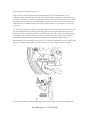
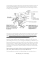
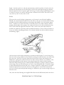
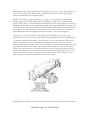
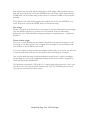
The steering linkage is located forward of the front cross member. The P Chassis linkage is
illustrated below. Steering effort is transmitted to left- and right-hand adjustable tie rods
through a relay rod. The relay rod is connected to an idler arm on the right and to the
pitman arm on the left. The fit of the shafts in the linkage support assemblies should be tight
with end play not exceeding .003. If it exceeds .003 inches in either assembly, adjust to
within 0 to .003 inches. Set large lock nut torque cap to 25 ft. lbs. and then loosen 1/16 turn
and tighten lock nut. If there is side play, replace the bushings. Lube the linkage under
'normal' conditions every 7,500 miles or every 3,000 miles if used in 'dusty' conditions. The
“support assembly” in the illustration below is also known as a “bellcrank”. These two
bellcranks are obvious points for improvement. More modern versions are much more
heavy duty, the SuperSteer version is one to consider. Expensive, but one of the best
improvements to make for handling.
Many motorhomes sit in storage for a long time between use. That steering damper (it's
really a shock absorber) can accumulate rust on its horizontal exposed rod. If it does get
heavily rusted and you just jump in after a long storage period and drive off, that rusty rod
may rip up the seal as soon as it moves inward when you turn the steering wheel. Good idea
to check it and possibly clean it off. Turn the steering wheel so as to extend the rod fully
while you check it. If it's badly rusted, it's probably a good idea to replace the damper. Same
thing applies to the shocks. Think about some preventive measures added to your preMain Body Page 3 of 38 Total Pages
storage checklist to help prevent this situation. Check the damper attachments to make sure
they are tight. Rubber bushings should be replaced if they are worn, cracked or crushed.
Check for leaks or noisy operation(it's a shock absorber). In 1991 the GM part number of
the damper changed to 22011982.
The steering is a recirculating ball type and needs basic checks for fluid level and condition
(ever think of changing that fluid?), drive belt tension, loose mountings, and loose pump
pulley. If the power steering pump needs to be replaced, be aware that the motorhome
version is different from the standard Commercial P-Series version. It is a stronger pump
with higher pressure ratings. The wrong one will definitely affect steering effort.
Shocks are generally checked for leaks, bad bushings or damage from getting hit by road
junk and being bent. However, if you are chasing down bad handling, a worthwhile step is to
disconnect the lower part of each shock and find out if it really has resistance to movement,
both up and down. You might be surprised. Always replace in pairs. Don't forget to look at
the mounts for breaks or broken welds. Replacing with a stronger rear shock may require
reinforcement to the rear mounts. Instructions should be with the shocks, and may require
some welding.
Improvements are easily made with these shocks by replacing with modern heavy
duty versions. Bilstein and Koni make for excellent upgrades here.
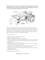
The front stabilizer bar (see below) has 4 rubber bushings, one at each end and two on
Main Body Page 4 of 38 Total Pages
frame mounts. Make sure those mounts are tight and all the bushings are in good shape. An
improvement to this stabilizer bar is to replace it with a much stronger version such
as the IPD 1 5/8” version and use polyurethane bushings. The 1 5/8” bars available
are 10 to 12 times stronger than the stock 1 1/4” sway bar.
The front wheel bearings require lube every 12,000 miles with high-temperature grease –
really. Check the bearings by raising the motorhome and supporting it at the front lower
control arm on each side. Now you can spin the wheel and check for noise or roughness. To
check for tight or loose bearings, grip the tire at the top and bottom and move the wheel
assembly in and out on the spindle. If hub assembly movement is less than .001 inch (too
tight) or more than .005 inch (too loose), adjustment is needed.
The adjustments steps are:
1.
2.
3.
4.
Remove the hub cap or wheel disc from the wheel.
Remove the dust cap from the hub.
Remove the cotter pin from the spindle and spindle nut.
Tighten the spindle nut to 12 ft. lbs. while turning the wheel assembly forward by hand to
fully seat the bearings. This will remove any grease which could cause excessive wheel
bearing play later.
5. Back off the nut to the “just loose” position.
6. Hand tighten the spindle nut. Loosen the spindle nut until either hole in the spindle lines
up with a slot in the nut (not more than ½ flat).
7. Install the new cotter pin. Bend the ends of the cotter pin against the nut. Cut off the
extra length to ensure that the ends will not interfere with the dust cap.
8. Measure the looseness in the hub assembly. There will be from .001 to .005 inch end play
when properly adjusted.
9. Install the dust cap on the hub.
10.Replace the wheel cover & hub cap.
Main Body Page 5 of 38 Total Pages
Doesn't sound like something you can easily determine? Take it to a mechanic you trust.
Air Bags
Air bags are an interesting item to folks with this chassis. Leaks can be located by removing
the bag from the vehicle, inflating it and submerging it – just like looking for a tire leak.
Actually, if it doesn't hold pressure, you have a leak. The logical repair is a replacement. If
you replace, replace bags as a pair.
There are basic guidelines for inflation depending on which version of the P Chassis you
have. The air pressure should never be under 10 PSI unless you are removing/replacing the
airbag.
Air Bags Front:
For a 4,300-lb suspension, 40-50 PSI.
For a 5,000-lb suspension, 50 PSI.
For a 5,300-lb suspension, 70 PSI.
For a 5,500-lb suspension, 90 PSI.
The GM part number is 367762 for the bags used in the 4,300 and 5,000-lb suspensions.
The GM part number is 15631881 for the bags used in the 5,300 and 5,500-lb suspensions.
This is an Airlift H.D. Bag. The part numbers can be updated at any time, and a new part
number of 15731951 was released for 1984 through 1997, but your handy GM dealer should
be able to figure it out. Be aware that these front air bags are contributors to the GAWR
(Gross Axle Weight Rating) for the chassis. Underinflation actually will decrease the rating
and will undoubtedly affect handling. Overinflation makes the ride harder and doesn't really
add much to the rating.
REAR:
Rear air bags are NOT part of the original chassis as supplied by Chevrolet. They are either
added by the coach manufacturer or installed by after-market suppliers to cure sagging rear
spring problems. There is no reason to believe they can be used in the rear to cure
overweight problems unless other items in the rear suspension are also beefed up. Tag axles
added by a coach manufacturer generally use air bags instead of springs. You need to get the
inflation specs from the manufacturer. The good objective for having them as an add-on
AFTER the coach was manufactured, would be for the empty coach to sit level with almost
empty rear air bags, and then inflate to compensate for various loading configurations up to
whatever max the airbag manufacturer has specified.
If you are inflating any airbags to compensate for out-of-level problems, it might be
worthwhile to consider replacing the coil springs in front and/or getting new or re-arched
springs for the rear. Think in terms of the age of your motorhome. Springs do have a limit to
their life. The 'ride height' check we will do in a bit and the charts in Appendix A and B will
help with this determination. As one of the improvements, new springs can be exactly
Main Body Page 6 of 38 Total Pages
matched to the actual axle weight of your coach and you can eliminate the air bags
when done properly.
One improvement you might want to consider for the rear is installation of a rear
track bar. This will help with that “tail-wagging-the-dog” feeling you might be
experiencing, this is a good modification if you tow something heavy.
Weight
Wait a second. Before you start throwing new springs, bags, etc. at the motorhome, have you
checked its weight? You're looking for the GAWR. At a minimum, you should be able to
find the label that gives the rating for your motorhome for the front and the rear axle. Front
4,300 lbs. and rear 7,500 lbs. is a common combination for a short chassis motorhome with
a 137 inch wheelbase. Add them up and you come up with the GVWR (Gross Vehicle
Weight Rating) of 11,800 lbs for our example.
That 4,300 lbs. for the front means that each tire is expected to carry 2,150 lbs. In other
words, the front is expected to be balanced side to side. Same goes for the rear. 7,500 lbs.
means that each dual pair of tires is expected to carry 3,750 lbs. (that's 1,875 lbs. per tire).
This means these are the MAXIMUM weights at each corner of the motorhome. It was
designed for these weights. You can't simply put on a 'better' tire or overinflate the tire or
airbags to compensate for higher weight at one corner. Could be that the wheel bearings,
springs or the axle are the limiting factor and you might crunch something if you exceed a
corner weight.
Anyway, get it weighed. Preferably each corner separately. You might check with your local
police and find out if they will help. They stop large trucks on the highway and conduct
random weight checks – so they have the equipment and may be willing to help you since
you are pursuing a safety aspect of driving your coach.
Once weighed, you may find your handling problem real quick. First, you cannot exceed the
maximum for the corner. Second, you really want to be balanced side-to-side on each axle
for best handling. Move stuff around until you can achieve this. Incidentally, weigh with the
same maximum configuration that duplicates how you travel. Full fuel tank, full fresh water.
If you travel with much in the holding tanks, you should also take that into consideration
and try to duplicate it – maybe even fill them up too. Load up with all the clothes, tools,
passengers, etc. that you normally carry. Make sure you are in the driver's seat or a
representative amount of weight has been placed there. You're not going to be graded on
this by anyone but yourself (well, maybe your spouse). You may find you have to change
some habits and dump tanks more often, carry less goodies, carry less water, lose some
weight.........
At this point, worn parts are taken care of and the motorhome is within weight parameters.
We are almost ready to head to the alignment shop. Maybe you have even added some of
Main Body Page 7 of 38 Total Pages
the suggested improvement parts.
Almost.
How about those tires?
Tires
No brand or type tire recommendation is presented here. However, the first rule is that you
do not mix different types of tires on the vehicle such as radial, bias and bias-belted tires
except in emergencies. Best option is that all tires on an axle are the same brand, type of
tread and same age. A 'highway' (also known as 'steering') version for the front and a
'traction' version for the back is OK. Current recommendation is to replace any tire that is 5
to 6 years old. Unless you drive the motorhome quite a bit, chances are they will have 7080% of the tread still left on them after 5 or 6 years. Check around – especially with your
local tire dealers. You might find someone that puts on a lot of miles on a light truck that
will buy your old tires. They may use them up in a matter of months, before they really get
too old, and you can sometimes get up to half the price of the new ones. Win-win for both
of you.
The next rule is that the tire is of adequate capacity for the load it is required to carry and
you keep it inflated accordingly.
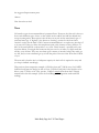
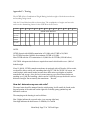
That previous front suspension example (4,300 lbs. front and 7,500 lbs. rear) for GAWR
indicated each front tire had to be able to carry 2,150 lbs. Each pair for the back has to be
able to carry 3750 lbs. or 1875 lbs. per tire. I added a sample chart from the P Chassis
manual below for this example. (Note the Load Range tire designation under each PSI
reading.)
Main Body Page 8 of 38 Total Pages
7.50-16 Bias Ply
30
PSI
C,D,
E
Lbs per
1620
tireSingle
Lbs per
1430
tireDuals
35
C,D,
E
40
C,D,
E
45
C,D,
E
50
D,E
55
D,E
60
D,E
65
E
70
E
75
E
1770
1930
2060
2190
2310
2440
2560
2670
2780
1565
1690
1815
1930
2040
2140
2245
2345
2440
Looks like 50 PSI would be a good choice for both the front and rear tires in the chart
above. The placard for this particular motorhome said 60 PSI. This is probably because of
the accepted rule to add 5 – 10 PSI if you intend to hit 65mph or better and also to help
cover a bit of loss between air checks. A Load Range D or E tire will do the trick if you
never cold inflate over 60 lbs. If you think you need 65 lbs., A Load Range E tire would be
required. Incidentally, many of these tires have a maximum speed rating on them. 65Mph
max is not uncommon. Also, Bias Ply tires are probably not what you will use today.
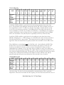
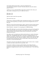
Looks like 50 PSI would be a good choice for the radial tire in the chart below from
Michelin. Bumping by 5 – 10 PSI will get you to 60 PSI for the same reasons noted above.
Note that this chart says “per position”. That means the left rear, right rear, left front or
right front. That also means that the capacity listed for the rear duals is for a PAIR of tires.
These Radial tires are maximum rated for 3,042 lbs. each – when inflated to 80 PSI. That
doesn't mean you can put 80 PSI in each tire and increase the capacity for the axle. Nor
should you just inflate to the max without a reason. Overinflation is almost as bad as
underinflation for handling. All you are really doing by adding too much air is making the
ride harder, and messing up the handling. Do it right. There is an optimum pressure for your
tires, giving the highest possible grip. Any pressure over this will bulge the tread in the center
causing a loss of traction because there is less rubber in contact with the road, and any
pressure under this will cause excess distortion of the tire and a loss of traction.
LT235/85R16 LRE
PSI
35
40
Lbs per
position- 1700 1870
Single
Lbs per
position- 3090 3400
Duals
45
50
55
60
65
70
75
80
2030
2205
2335
2485
2623
2765
2905
3042
3690
4015
4250
4520
4765
5030
5290
5556
One more thing. Use the size tire recommended by the manufacturer. This is especially
important to ensure the tires match the rim's capacity, fit in the wheel well, and in the case of
Main Body Page 9 of 38 Total Pages
duals, are properly spaced from each other. If the duals touch sidewalls, they won't last and
are a hazard. (If you do decide on bigger or wider tires, work with a pro. Substituting
LT235/85R16 tires in place of 7.50-16 tires is probably not going to work in the duals
position without changing rims too – they would be too close together.) By the way, a bent
rim can cause problems, but should be caught when you have the tires balanced. Mention
that you want this checked to ensure someone with experience looks at the rims instead of
the new guy.
Current load and inflation information for popular auto tire sizes may be obtained from your
local tire dealer, the manufacturer's web site or tables may be obtained free by sending a
stamped, self-addressed business-size envelope to "Tables," Tire Industry Safety Council,
Box 1801, Washington, D.C. 20013. See the Appendices in this document for an extract
from the P Chassis manual with inflation info. The chart for tire inflation in one of the
appendices is from the service manual and is not current (it was published in 1995). It is
provided as a general guideline – but exact inflation pressures should be obtained from your
tire manufacturer for your brand and model of tire.
Don't forget to torque the wheels correctly using a torque wrench – NOT an impact tool.
8-bolt wheels (9/16 bolts) get 140 ft. lbs.
5-bolt front wheels and 10-bolt rear wheels get 180 ft. lbs.
We're still not quite ready for that alignment.
There are two more items to check. Ride height and frame angle. Both affect the caster that
will be set during the alignment. Without these numbers, you CANNOT come up with a
valid CASTER setting. This is the one that most frequently is set incorrectly.
Ride Height
Ride height is checked at four points. Tolerance for manufacture of the springs is ± ½ inch.
If the side-to-side measurements are not equal, or within the tolerance of 1”, some work
needs to be done. Also, the front-to-rear ratio for each side should be close to the same.
However, there are steps that can be taken to fix or correct these measurements quite a bit.
Ride height measurement points are specified by the manufacturer. On some vehicles, it is
from the frame to the ground, a specific point on the underside of the body to ground, or
between components as specified by the manufacturer.
The measurement for the P Chassis is taken as illustrated in the next diagrams. The best
circumstance is to disconnect one end of each shock absorber before making this check
(good time to check the shocks too) and the motorhome must be on an absolutely level
surface. If the surface is not perfectly level, you can shim to level by placing squares of
plywood under each wheel until the tops of the plywood at each corner are at the same level
Main Body Page 10 of 38 Total Pages
height. Another option is to take the measurements, mark the position of each corner tire
and turn the motorhome around 180 degrees, park in the same marks facing the opposite
direction and check the four points again. An average of each reading should bring you close
to actual. Of course, you need to start this with an almost-level location. This won't work
very well if you do it on the side of a hill.
REAR:
The reason the rear ride height is important to us is because it can affect the handling.
Basically, the measurements should be the same side-to-side, just as the front. Before doing
anything, check the rubber bushings on the springs and shackles. Look for broken spring
leaves – evidence of a crack in the side of a leaf may be the only visible evidence without
complete disassembly of the springs. Also make sure there are no obvious broken mounts.
The U-bolts should be tight and not broken. Take a close look at the welds where the
shackles are attached to the frame and the shackles themselves. If one of these is broken or
loose, you will have handling problems. (You already checked the shocks and their mounts
and bushings, right?)
One last item to check before attempting to measure the ride height. You are looking for a
bent rear axle housing. Indications are found by noticing the inner dual tires wear more than
the outer ones. Also look for grease lube leaks at the bottom of the axle housing at the
differential. A split gasket near the bottom area almost always indicates an overload, or flex
and housing distortion, which destroys the gasket between the carrier and the housing.
Failed rear wheel bearings may be another possible indication to prompt a check for a bent
axle housing. They can also fail because of a lack of rear differential lube. (You didn't forget
to check this during the last lube did you?) A couple of potholes at high speed on a heavilyloaded motorhome can do the trick. However, if the previous owner of the motorhome
took care of these leaks and replaced bearings, it is difficult to spot a bent housing except for
inner tire wear.
Also, since the wheel bearings are supplied with lube from the differential, make sure that it
Main Body Page 11 of 38 Total Pages
is full to the appropriate level and changed on a regular basis. All lubricants lose
effectiveness over time. Every four oil changes ('normal' or 'dusty' cycle) will do the job. The
differential can run a temperature approximately 100 degrees above the ambient
temperature. Air passing over the housing is the only thing that carries away this heat. Make
sure the housing is not severely covered with dirt or dried mud which will insulate and help
retain and increase the heat. (Go back to the car wash and hit the housing with the highpressure spray.) The exhaust pipe shouldn't be too near the housing. Don't mix lubricant
brands – this can cause foaming and reduce heat transfer. If you run at high speeds, it can
cause aeration and heat transfer capability will be diminished.
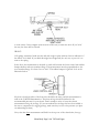
Ride height for the P Chassis rear is checked on each side between the top of the axle tube
and the bottom of the frame above the axle tube. You are looking for this “D” measurement
to be equal side-to-side. If these are not equal, your weight side-to-side may be unequal or
springs may be sagging. In any case, an attempt should be made to get these as equal as
possible. Check Appendix B for information on the rear spring capacities for various P
Chassis models. (The illustration has a single on the left and a dual on the right because it
applies to either situation including non-motorhome versions of the P Chassis.)
Here is a case study right out of the Chevy P Chassis manual:
“GM CASE STUDY: A motor home was loaded to a maximum GVW, both front and rear. Sufficient air
was applied to a typical after-market leveling device to establish a 'dead-level' frame. In this case study,
wheel travel was limited to ¾ inch before the after-market device “went solid metal-to-metal” between
the rear axle and the frame. This severe limitation on wheel travel promoted a “crash-through situation”
on even the slightest bump. The force from this “crash-through situation” was transmitted into the
vehicle frame, rear axle and the coach itself. GM has determined that these types of after-market leveling
devices can be very damaging to the motor home and also can affect vehicle handling and are therefore
potentially very dangerous.
“If vehicle weights cannot be shifted due to vehicle build, consideration should be given to adding spring
leaves or spacer blocks.”
The spacer blocks mentioned above refer to making the side-to-side rear ride height
Main Body Page 12 of 38 Total Pages
measurement equal. (This supposes that the weight is not in excess of the axle rating and you
have moved your movable stuff around to help balance the side-to-side weight.) Spacer
blocks are fabricated in local machine shops.
NOTE: The addition of a spacer block ( 2 ½” wide, 6” long, thickness as needed) can
actually improve overall ride quality while the addition of a leaf tends to reduce the ride
quality of the vehicle. A new motorhome manufactured with an extra spring on one side is a
bad design. They didn't get the weight balance right and compensated with the springs. You
would also have to be very careful in this situation with the tire inflation. The heavier side is
the weight to use to determine the correct pressure for all tires on that axle. You cannot
simply divide the total axle weight in half in this situation – that can be dangerous.
The thickness of the spacer block is determined by the difference in the side-to-side
measurements at the rear axle. Once the thickness is determined and the block fabricated, a
¾ inch hole is drilled in the center. A slip-fit dowel, as long as the thickness of the spacer
block, is inserted into the hole of the block. This keeps the center of the axle and the
existing spring properly aligned. The U-bolts will need to be replaced with longer ones if the
spacer block is more than ¾” thick. Also, the rear flexible brake hose that runs from the
frame to the axle may need to be lengthened since you are increasing the distance from its
mount on the frame to the connection on the axle. Check by slowly lifting the rear by the
frame and allow the rear axle to hang loose. Be careful to check while doing this so you
don't accidentally rip up that brake hose in case it is too short.
Modifying the rear side-to-side measurements will affect the front side-to-side measurements
Main Body Page 13 of 38 Total Pages
to some extent. Once complete with the work in the rear, re-check the front. If you 'twist'
the rear, the front will be affected.
FRONT:
Coil springs sometimes break near the end and wedge in place without obvious indication of
the failure. Look hard. If you think this might have happened, the only way to prove it is to
remove the spring.
In the front, the measurement is checked on each side between the lower control arm rubber
bumper bracket and cross member flange. This measurement must be perpendicular to the
cross member flange. It is from “iron to iron”. The rubber bumper is ignored. Look at the
illustration below.
Key here is that both sides of the front axle should be the same, and this measurement is
used in the CASTER determination. The front air bags should be inflated to the
recommended pressure for your chassis. Don't attempt to raise or lower the chassis
measurements using the air bags. (If your motorhome has air bags that have been added to
the rear to compensate for sagging springs, make sure they are set to the pressure you plan
on maintaining in them.)
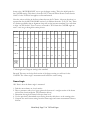
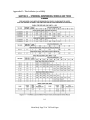
Now, take that front measurement and find it in the top row of the chart below, then go
Main Body Page 14 of 38 Total Pages
down to the “MOTOR HOME” row to get the degree setting. This is the initial point for
the CASTER setting. This chart is from the 1995 “Chevrolet Motor Home Chassis Service
Guide” for the P Chassis but applies to all manufactured.
Note the various vehicles in the first column that use the P Chassis. Also note that there is a
separate line for the MOTOR HOME version. It is different from the “P-20, 30” line. There
is a distinct possibility that an alignment shop will use the incorrect numbers if you tell them
to align “my P30 chassis”. But of course, we intend to TELL them the CASTER angle we
want – once we go through this entire process.
INCHES
1 1/2
1 3/4
2
2 1/4
2 1/2
3 1/2°
3 1/4°
3°
3°
2 3/4°
2 1/2°
2 1/4°
3°
2 3/4
3
3 1/4
3 1/2
3 3/4
4
4 1/4
4 1/2
4 3/4
2 3/4°
2 1/2°
2 1/4°
2°
2°
1 3/4°
1 1/2°
2°
1 1/2°
1°
3/4°
1/2°
1/4°
0°
-1/4°
2 1/2°
2 1/4°
2°
1 3/4°
1 1/2°
1 1/4°
1°
1/2°
1/2°
1/4°
0°
5 1/2°
5 1/4°
5°
4 3/4°
4 1/2°
4°
3 3/4°
3 1/2°
3 1/4°
3°
5
G-10, 20
G-30
P-20, 30
CLASS A
MOTOR
HOME
(32 – 52)
3°
3” ride height and 5 degrees setting is the standard.
But wait! This may not be the final version of the degree setting you will use for the
CASTER. The “frame angle” measurement will affect the caster setting.
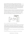
Frame Angle
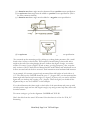
OK. Here is how the frame angle is measured:
1. Park the motor home on a level surface.
2. Place a protractor with a level gage against the bottom of a straight section of the frame
rail near the chassis midpoint. (See illustration below)
3. Determine the angle the frame rail slopes from level.
4. Use the previously-determined caster setting from the table above as the starting point.
5. Compute the actual caster setting from the frame angle and caster measurement taken as
follows:
Main Body Page 15 of 38 Total Pages
(a) A down-in-rear frame angle must be subtracted from a positive caster specification.
(b)An up-in-rear frame angle must be added to a positive caster specification. (This is
the most common situation.)
(c) A down-in-rear frame angle must be added to a negative caster specification.
(d) An up-in-rear frame angle must be subtracted from a negative caster specification.
(You can make up the measuring tool by picking up a cheap plastic protractor, file a small
notch at the 0 center on the flat side. Then capture a knotted string in that notch with a
weight at the end of the string hanging down to indicate the degree of angle - not rocket
science. Of course, if your eyesight is as bad as mine, get a big protractor.) Also, note that
early versions of the P Chassis Service Manual had the words 'added' and 'subtracted' in a &
b above reversed and c & d above reversed. Their instructions were backward and incorrect.
As an example, let's assume you previously measured front ride height on both sides as 4
1/2”. The table says the CASTER should be set to 3 ¼ degrees. But, you then measured the
frame angle and found an up-in-rear angle of 3 degrees. (b) above says you need to add that
figure and you wind up with a setting of 6 ¼ degrees. That's the figure you should tell the
alignment shop to use for CASTER – in this example.
If you should measure the frame angle on both sides of the motorhome and come up with
one side positive angle and one side negative angle, stop and get some help. But, this would
be rather extreme.
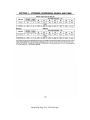
Two more settings to go for the alignment: CAMBER and TOE-IN.
Here's the table from the same 1995 manual. Note that there is no line for “P-20, 30.”
Interesting.
Main Body Page 16 of 38 Total Pages
MODEL
CAMBER
TOE-IN (IN.)
G10, 20
.5°
3/16”
G30
.2°
3/16”
.25° ± .25°
0° to .06°
CLASS A
MOTOR HOME (32 – 52)
Toe-in was reduced from 5/16 inch in 1985 as part of a GM trend reducing toe-in. If
equipped with radial tires, some tire manufacturers would suggest toe-in specifications of
1/32 inch to 1/8 inch. Basically, you want the tires parallel, if you can't get them exactly on
zero, make sure it is toward that .06 degrees of toe-in and NOT toe-out. All prior years of
this chassis should use the specs above.
Alignment
OK, we fixed everything we could fix and everything else is in pretty good shape with
weights balanced and tires and airbags inflated correctly.
Remember: (Appendix D)
CASTER affects your vehicle's low-speed steering, high-speed stability as well as how well
your vehicle drives in a straight line (on-center feel). Too little caster will cause your car to
"wander" and make it feel unstable at high speeds. Too much caster causes hard steering and
can also result in excessive road shock and shimmy. Caster does not affect tire wear.
The CAMBER angle is designed and adjusted per vehicle to keep the tires on the outside of
a curve flat on the ground during a turn. If you have too much positive camber, your tires
will wear on the outside. Too much negative camber will wear them on the inside. If there is
too much of a difference between the camber settings on the front wheels, the vehicle will
tend to pull sharply to one side.
TOE settings affect the handling characteristics of a vehicle in turns. Toe-in introduces
Understeer going into a curve and may make the vehicle feel like the back end is trying to
come around to the front end. Toe-out introduces Oversteer in a curve and makes the
vehicle feel like it is "diving" into the turn too sharply. If the tires are toed-in too much, the
tread will be "worn" off, starting from the outside edges. If they are toed-out, the wear will
start from the inside. This type of wear is called "feathering" and can be felt by running your
hands across the tread of the tire.
Seems we are ready to now tell the alignment guys in our example how we want things set.
We already know the coach is level, not overweight and in good shape because we fixed
everything. For our example we tell them to set CASTER for 6 ¼ degrees, CAMBER at .25
degrees plus or minus .25 degrees and TOE-IN at 0 degrees or slightly plus up to .06
degrees.
After the wheel alignment is completed take the vehicle for a test drive. Note any wandering,
drifting or pulling that would indicate that the alignment is still out-of-spec.
Main Body Page 17 of 38 Total Pages
CONGRATULATIONS!
Your Class A motorhome should no longer be yanking on your shoulder sockets and you
can enjoy the next trip a little better. You also should now have a better feel for why some
maintenance needs to be done, the airbags should be consistently inflated to the same
pressures and the tire pressures maintained properly. They all affect handling and safety.
The Appendices following this are for further information.
A and B help in determining if your springs are up to snuff.
C will give you the ability to interpret your VIN number.
D is basic information on the adjustable points of an alignment.
E is a couple of pages from the P Chassis manual with tire inflation information. This is
generic and you should use the manufacturer's chart for your brand and model tire.
F is derived from the P Chassis manual to help you determine if you are exceeding the
towing recommendation for your configuration. You might be surprised here.
Good luck,
Mike Cebula
Main Body Page 18 of 38 Total Pages
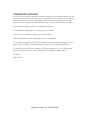
Appendix A – Front Load Height Curve
Known weights compared to actual dimensions can determine if the spring is performing
according to its rating. Actual measurements will be ±½-inch on the chart and normally
considered within the spring makers production capability.
Main Body Page 19 of 38 Total Pages
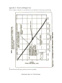
Appendix B – Rear Load Height Curve
Main Body Page 20 of 38 Total Pages
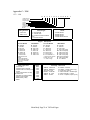
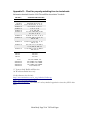
Appendix C – VIN
1979 - 1980
C P Y 3 7 9 3 1 0 0 0 0 1
1. Selling Division
2. Chassis Type
3. Engine Description
4. Series
5. Body Type
6. Model Year
7. Assembly Plant
8. Vehicle Sequence
Number
1.
Selling Division
C - Chevrolet
T - GMC Truck
1973-75 Models
Q - 250 Six
T - 292 Six
X - 307 V8
V - 350-2 V8
Y - 350-4 V8
M - 400-4 V8
Z - 454-4 V8*
L - 454-4 V8**
2.
Chassis Type
C - Conventional
K - 4-wheel drive
G - Forward Control w/unitized
body
P - Forward Control
Engine
1976 Models
D - 250 Six
T - 292 Six
Q - 305-2 V8
V - 350-2 V8
L - 350-4 V8
U - 400-4 V8
S - 454-4 V8*
Y - 454-4 V8**
* 6000-lb and under
GVWR
** Over 6000 GVWR
***Conventional models
only (1977), All models
(1978-79)
1234-
10/1500
20/2500
30/3500
10/1500
3.
Description
1077-79 Models
D - 250 Six
T - 292 Six
U - 305-2 V8
L - 350-4 V8
R - 400-4 V8
S - 454-4 V8***
Y - 454-4 V8****
Z - 5.7L Diesel*****
****Moror Home Chassis
models (1977 only)
*****1078-79 only)
5.
Body Type Code
1 - 4-door Cab
2 - Forward Control Chassis
3 - Chassis-Cab or Cutaway Van
4 - Pickup
5 - Chevy Van/Vandura or Step
Van/Value Van
6 - Suburban or Sportvan/Rally
7 - Motor Home Chassis
8 - Blazer/Jimmy Utility
9 - Stake
6.
Model
Year
3 - 1973
4 - 1974
5 - 1975
6 - 1976
7 - 1977
8 - 1978
9 - 1979
A - 1980
4.
Series
Series
Series
Series
Series w/F44l
1980 Models
D - 250 Six
T - 292 Six
G - 305-2 V8
L - 350-4 V8 (LS9)
M - 350-4 V8 (LT9)
P - 350-2 V8 (LF5)
R - 400-4 V8 (LF4)
S - 454-4 V8 (LF8)
W - 454-4 V8 (LE4)
X - 400-4 V8 (LE4)
Z - 5.7L Diesel
7.
Assembly Plant Code
A - GMAD - Lakewood
B - GMAD - Baltimore
F - Chevrolet - Flint
J - GMAD - Janesville
S - GMAD - St. Louis
V - GMTC - Pontiac
Z - GMAD - Fremont
O - GMTC - Pontiac (Vans only)
3 - Chevrolet - Detroit
4 - GM of Canada - Scarborough
5 - GM of Canada - London
8 - Isuzu - Fujisawa, Japan (LUV)
Main Body Page 21 of 38 Total Pages
1981 – 1983
1 G B J P 3 7 W ? C 3 3 0 4 6 1 1
Country
1 = U.S. Built
2 = Canadian Built
J =Japan Built
Manufacturer
G = General Motors
8 = Isuzu Motors
A
B
C
D
O
T
Y
5
6
Type
Chevrolet Bus*
Chevrolet Truck Incomplete
Chevrolet Truck
GMC Truck Incomplete
GMC Bus*
GMC Truck
Isuzu
GMC MPV
Chevrolet MPV
* 10 or more passengers
GVWR Range
B 3001 - 4000
C 4001 - 5000
D 5001 - 6000
E 6001 - 7000
F 7001 - 8000
G 8001 - 9000
H 9001 - 10,000
J 10,001 - 14,000
K 14,001 - 16,000
Code Series
1 - 1/2 Ton
2 - 3/4 Ton
3 - 1 Ton
8 - 1/2 Ton (ElCamino/
Caballero)
Body Type
0 Sedan Pickup
1 Hi-Cube/Cutaway/
Utility Box
2 Forward Control
3 Four-Door Cab
4 Two-Door Cab
5 Van
6 Suburban
7 Motor Home Chassis
8 Utility (Jimmy/Blazer)
9 Stake
Line and Chassis
C Conventional Cab
4x2
K Conventional Cab
4x4
P Forward Control
4x2
G Chevy Van/Vandura,
Sportvan/Rally & Cutaway Van
L LUV
4x2
R LUV
4x4
S Conventional Cab*
4x2
T Conventional Cab*
4x4
W El Camino/Caballero
* S-10/15
Production Sequence Number
100,000 - 500,000 - Chevrolet
500,000 - 999,999 - GMCr
Check Digit
Year
B - 1981
C - 1982
D - 1983
E - 1984
F - 1985
G - 1986
*A
A
B
C
D
F
G
*H
H
*J
J
*K
L
M
N
P
S
T
W
Y
*Z
Engine
3.8L V6
(LD5)
1.9L L4
(Isuzu)
2.8L V6
(LR2)
6.2L Diesel (LH6)
4.1L L6
(LE3)
5.0L V8
(LF3)
5.0L V8
(LG9_
5.0L V8
(LG4)
5.0L V8
(LE9)
4.4L V8
(l39)
6.2L Diesel (LL4)
3.8L V6
(LC3)
5.7L V8
(LS9)
5.7L V8
(LT9)
1.8L L4
(Isuzu)
5.7L V8
(LF5)
2.2L Diesel (Isuzu)
4.8L L6
(L25)
7.4L V8
(LE8)
2.0L L4
(LQ2)
5.7L Diesel (LF9)
* For El Camino/Caballero models only
Main Body Page 22 of 38 Total Pages
Assembly Plant
B - Baltimore, MD
F - Flint, MI
J - Janesville, WI
S - St. Louis, MO
E - Pontiac East, MI
V - Pontiac, MI
Z - Fort Wayne, IN
1 - Oshawa, ON
2 - Moraine, OH
3 - Detroit, MI
4 - Scarborough, ON
7 - Lordstown, OH
8 - Shrieveport, LA
0 - Pontiac, MI
1984 - 1995
1 G B J P 3 7 N 8 M 3 3 0 4 6 1 1
Nation of Origin
1 = U.S. Built
2 = Canadian Built
3 = Mexico Built
Manufacturer
G = General Motors
Code Make
A Chevrolet Bus*
B Chevrolet Incomplete
C Chevrolet Truck
D GMC Incompletge
E Cadillac Incomplete
H GM of Canada Bus
T GMC Truck
IGJ GMC VanBus
IGK GMC MPV
IGN Chevrolet MPV
* Van with 4th seat
GVWR/BRAKE SYSTEM
B 3001 - 4000
Hydraulic
C 4001 - 5000
Hydraulic
D 5001 - 6000
Hydraulic
E 6001 - 7000
Hydraulic
F 7001 - 8000
Hydraulic
G* 8001 - 9000
Hydraulic
H 9001 - 10,000 Hydraulic
J 10,001 - 14,000 Hydraulic
K 14,001 - 16,000 Hydraulic
L 16,001 - 19,500 Hydraulic
* Includes G-Van Bus
Code Series
1 - 1/2 Ton
2 - 3/4 Ton
3 - 1 Ton
0
1
2
3
4
5
6
7
8
9
Check Digit
Code Body Type
Pickup Panel Delivery
Hi-Cube Cutaway Van
Forward Control
Four-Door Cab
Two-Door Cab
Van
Suburban
Motor Home Chassis
Utility (Jimmy/Blazer)
Stake
Line and Chassis Type
R Conventional Cab
4x2
D Military Truck
4x4
V Conventional Cab
4x4
G Van
4x2
P Forward Control
4x2
S Sm Conventional Cab 4 x 2
T Sm Conventional Cab 4 x 4
M Sm Van
4x2
Production Sequence Number
Year
E - 1984
F - 1985
G - 1986
H - 1987
J - 1988
K - 1989
L - 1990
M - 1991
N - 1992
P - 1993
R - 1994
S - 1995
T - 1996
V - 1997
W - 1998
X - 1999
Assembly Plant
B - Baltimore, MD
F - Flint, MI
J - Janesville, WI
S - St. Louis, MO
E - Pontiac East, MI
V - Pontiac, MI
Z - Fort Wayne, IN
1 - Oshawa, ON
2 - Moraine, OH
3 - Detroit, MI
4 - Scarborough, ON
7 - Lordstown, OH
8 - Shrieveport, LA
0 - Pontiac, MI
Engine Type and Make
Producer
Type
RPO
C DDAD
6.2L V8 Diesel LH6
E Pontiac
2.5L L4 TBI
LN8
F Powertrain 6.5L V8 Diesel
L65
H Chevrolet 5.0L V8 TBI
LO3
J Chevrolet 7.4L V8 SFI
L29
K Chevrolet 5.7L V8 TBI
LO5
M Chevrolet 5.7L V8 4BBL
LT9
N Chevrolet 7.4L V8 TBI
L19
R Chevrolet 2.8L V6 TBI
LL2
W Chevrolet 7.4L V8 4BBL
LE8
Z Chevrolet 4.3L V6 TBI
LB4
Main Body Page 23 of 38 Total Pages
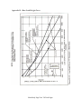
Appendix D – An Alignment Primer
Main Body Page 24 of 38 Total Pages
Appendix E – Tire Inflation (as of 1995)
Main Body Page 25 of 38 Total Pages
Main Body Page 26 of 38 Total Pages
Appendix F – Towing
The GCWR (Gross Combination Weight Rating) includes weight of both the motorhome
and anything being towed.
Only the V8 and diesel models are shown here. The combination of engine and rear axle
ratios are the determining factor for the GCWR on the P Chassis.
GCWR
10,000
10,500
11,000
ENGINES
11,500
12,000
12,500
13,500
14,000
14,500
15,000
16,000
19,000
4.10
4.56
4.88*
REAR AXLE RATIOS
5.7L (350)
V8 GAS
3.08
6.2L V8
DIESEL
3.42
3.23
3.42
3.73
4.10
3.73
4.10
4.56
7.4L (454)
V8 GAS
3.21
4.56
5.13*
3.42
3.73
*Motorhome chassis only.
NOTE:
GCWR for unit with 4L80E transmission is 21,000# with GVWR of 16,500#.
For GVWRs less than 16,000#, the maximum GCWR is 19,000#.
Max GCWR with the 475 transmission is 19,000# for all GVWRs (1990 & before).
CAUTION: Adequate size brakes are required on towed vehicle/trailers over 1,000 of
loaded weight.
If our 11,800 lb. GVWR example motorhome is equipped with a 454 and a 4.88 rear axle,
we should be able to safely tow something that is up to 7,200 lbs. WOW! Of course, we
would equip it with remote brakes because those hills seem to get higher as both the
motorhome and we age. Also, the law in some states says you need remote brakes on
anything over 1,000 lbs. Installing a hitch rated at 10,000 lbs just says the hitch is safe at
that towed weight. Not necessarily the motorhome. Be safe.
How do I determine my rear axle ratio?
The actual ratio should be stamped into the axle housing. It will usually be found on the
forward portion of the axle tube on the right side. Probably pretty gummed up and
difficult to read too.
The stamping on the housing is read as follows:
First 3 digits indicate the rear axle ratio. (you can stop right here)
Next digit indicates the build source C=Buffalo, K=Canada
Main Body Page 27 of 38 Total Pages
Next 3 digits indicates the day built - expressed in Julian Date form
Last digit indicates the shift 1=1st shift, 2=2nd shift. (Don't have any idea what the
purpose of this is.)
Another way is to try and find the RPO codes sticker somewhere in the coach, your
Chevy dealer can interpret it for you. The RPO info I have is:
RPO 066 is 4.10
RPO 005 is 4.56
Don't have info for the 4.88 or any others.
Those are the easy ways.
The hard way is a little more difficult with a motorhome than with a car, but is absolutely
the most accurate especially if you suspect a previous owner changed out the rear end here goes:
Raise the rear axle off the ground, support, support, chock front wheels and then support
some more to make sure it is safe. Transmission should be in neutral and emergency
brake off (chocks - remember?). You are going to be UNDER this thing.
Make a BIG chalk mark on one side of the driveshaft that can be seen from alongside the
vehicle (you don't really want to be under it very long for this). Make a corresponding
mark on the side of the housing that aligns with the driveshaft mark, on the pinion
housing would be good.
Now make a mark on the right rear tire either exactly at the top or exactly at the bottom.
Maybe make a corresponding chalk mark on the fender for alignment purposes. The
objective is to SLOWLY rotate that tire one complete revolution while someone watches
the drive shaft chalk marks and counts the revolutions. (The tire on the other side of the
driveshaft should be turning at the same rate. Both wheels off the ground is the better
procedure for a limited slip differential.)
The number of turns the driveshaft makes indicates the ratio. In other words, 4 complete
revolutions and almost another full one is probably a 4.88.
If you choose to lift just one of the rear wheels off the ground, change the above
procedure by rotating the tire TWO full turns. (With one wheel on the ground and not
spinning, the ring gear turns half as much. 2 turns of the lifted wheel = 1 turn of the ring
gear.)
Main Body Page 28 of 38 Total Pages
Appendix G – Chart for properly matching tires to rims/wheels.
Information obtained from the 1994 Tire and Rim Association Yearbook.
TIRE SIZE
(1)
APPROVED RIM CONTOURS (2)
LIGHT TRUCKS
6.50 16LT
7.50 16LT
LT225/75 16
41⁄2K, 4.50E, 5K, 6K, 6L
5.50F (SDC), 6K, 6L, 61⁄2L, 7L
6J, 61⁄2J, 6K, 61⁄2K, 61⁄2L, 7J, 7K, 7L
LT245/75 16
LT265/75 16
LT285/75 16
LT215/85 16
61⁄2J, 61⁄2K, 61⁄2L, 7J, 7K, 7L
7J, 7K, 7L, 8J, 8L
8J, 8L, 8LB, 8KB
51⁄2J, 51⁄2K, 5.50F (SDC), 6J, 6K,
LT235/85 16
LT255/85 16
61⁄2J, 61⁄2L, 7J, 7K, 7L
6J, 6K, 6L, 61⁄2J, 61⁄2L, 7J, 7K, 7L
61⁄2J, 61⁄2L, 7KB, 7J, 7K, 7L, 8J,
8KB, 8L, 8LB
LT235/70 16
6J, 6K, 6L, 61⁄2J, 61⁄2K, 61⁄2L, 7J, 7K,
7KB, 7L, 71⁄2J
LT255/70 16
61⁄2J, 61⁄2K, 61⁄2L, 7J, 7K, 7KB, 7L,
LT275/70 16
71⁄2J, 8J, 8KB, 8L, 8LB, 81⁄2J
7J, 7K, 7KB, 7L, 71⁄2J, 8J, 8KB, 8L,
8LB, 81⁄2J, 9J
8.00 16.5
8.75 16.5
9.50 16.5
8 19.5
225/70R 19.5
245/70R 19.5
265/70R 19.5
305/70R 19.5
6.00, 6.75
6.00, 6.75
6.75, 8.25
5.25, 6.00, 6.00RW, 6.75
6.00, 6.00RW, 6.75, 6.75RW
6.75, 6.75RW, 7.50, 7.50RW
7.50, 7.50RW, 8.25, 8.25RW
8.25, 8.25RW, 9.00
A ' ' denotes both Radial and Bias tires.
An 'R' indicates Radial tires only.
Good reference sites for info:
http://www.trucktires.com/us_eng/technical/index.asp
http://www.accuridewheels.com/
http://www.us-tra.org/ (not much of a safety-minded organization since they SELL their
info)
Main Body Page 29 of 38 Total Pages
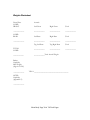
Weights Worksheet
From Plate:
GAWR
FRONT
Actuals:
Left Front
Right Front
Total
____________
____________
____________
____________
GAWR
REAR
Left Rear
Right Rear
Total
____________
____________
____________
____________
Tag Left Rear
Tag Right Rear
Total
TOTAL
GAWR
____________
____________
____________
____________
____________Total Actual Weight
Brakes
Capability
Max Weight
(digit 4 of VIN)
____________
VIN # _______________________________________
GCWR
Capability
(Appendix F)
____________
Main Body Page 30 of 38 Total Pages
Understanding motorhome weights
You've probably heard it said that a chain is only as strong as its weakest link. This theory
applies to motorhome chassis as well.
The chassis manufacturer establishes weight ratings and limitations based on the major
components of the system — the engine, transmission, brakes, axles, tires and frame. These
components are designed to accommodate a particular weight, and if they are overloaded,
their life expectancy diminishes rapidly.
So, it is important for motorhome owners to understand the various weight definitions used
by motorhome and chassis manufacturers. Of course, the next step is to have your
motorhome weighed after you have loaded it for travel to make sure it falls within the
various ratings.
Weight definitions
GVWR (gross vehicle weight rating): the maximum permissible weight of the fully loaded
motorhome, including liquids, passengers and cargo. The GVWR is equal to or greater than
the sum of the unloaded vehicle weight (UVW) plus the net carrying capacity (NCC).
GCWR (gross combination weight rating): the value specified by the motorhome
manufacturer as the maximum allowable combined weight of the motorhome and the
attached towed vehicle.
GAWR (gross axle weight rating): the maximum allowable weight each axle assembly is
designed to carry, as measured at the tires, including the weight of the assembly itself.
GAWR is established by considering the rating of each of its components (tires, wheels,
springs and axle) and rating the axle on its weakest link. The GAWR assumes that the load is
equal on each side of the vehicle.
RVIA weight label
In September 1996, the Recreation Vehicle Industry Association (RVIA) established a
requirement for its RV manufacturer members to disclose weight carrying information that
would assist both a buyer and an owner in understanding and complying with weight
limitations of motorhomes. The following terms and their associated weights are reflected
on a label, found in a cabinet inside the coach.
UVW (unloaded vehicle weight): the weight of the motorhme as built at the factory with full
fuel, engine oil and coolants. The UVW does NOT include cargo, fresh water, LP gas,
occupants or dealer-installed accessories.
NCC (net carrying capacity): the maximum weight of all occupants including the driver,
food, tools, LP gas, fresh water, personal belongings, dealer-installed accessories, and the
Main Body Page 31 of 38 Total Pages
tongue weight of the towed vehicle that can be carried by this motorhome. (NCC can be
determined by subtracting the UVW from the GVWR.)
It's important to look at the definition of each term, particularly the UVW and NCC. Note
that UVW is defined as leaving the factory with full fuel, oil and coolants. The NCC
represents how much "stuff," including fresh water, the motorhome can carry.
The UVW does not include the weight of any dealer-installed accessories, which means the
buyer must deduct the weight of these accessories from the NCC.
Keep in mind that NCC is the total carrying capacity. However, the distribution of the
weight plays a role. So, it may not be possible to load a motorhome to its NCC without
exceeding an axle or tire rating. Weighing your motorhome by individual wheel position
after you have loaded it is the only way to be certain that you are not exceeding any
limitations.
In September 2000, the RVIA modified the label to provide more detail for the
buyer/owner. The term NCC is no longer used. Two new terms are found on the label,
along with their associated weights:
SCWR (sleeping capacity weight rating): the manufacturer’s designated number of sleeping
positions multiplied by 154 pounds (70 kilograms).
CCC (cargo carrying capacity): the GVWR minus each of the following: UVW, full fresh
(potable) water weight (including water heater), full LP-gas weight, and SCWR.
This new label permits the buyer/owner to determine the carrying capacity (CCC) based on
a personal calculation of actual passengers carried, the amount of fresh water on board, and
the amount of LP-gas carried.
Use the RVIA label as a guide to narrow your selection of vehicles, but keep in mind its
limitations.
This information was provided by A'Weigh We Go, a national weight safety program that is now a service
of the Recreation Vehicle Safety Education Foundation (RVSEF). The Foundation sponsors nine RV
safety programs and conducts educational seminars.
How to weigh your motorhome
The first time to weigh your motorhome is even before you finalize the purchase. That way
you can determine whether the vehicle will meet your needs in terms of carrying capacity.
Weigh before you pay
Main Body Page 32 of 38 Total Pages
When purchasing a motorhome, you may not find a place to weigh your motorhome wheel
by wheel, as weighing experts recommend. However, you can weigh each axle. Then, you
can evaluate the placement of storage areas, liquid tanks, major appliances, slideouts,
generator, LP-gas tank, etc. to see whether the distribution of these heavy components could
cause problems. If the capacity is not reasonably distributed, you may have difficulty loading
the coach within its limits.
When buying or weighing a coach, you must have a good knowledge of your personal
weight carrying requirements. To help in your calculations, here are the approximate weights
(pounds per gallon) of the liquids motorhomes can carry:
water -- 8.3; A full 60 gallon water tank uses up nearly 500 pounds of your capacity!
gasoline – 5.6;
diesel fuel -- 6.8;
propane -- 4.2.
When determining your requirements, keep in mind that everything you put in the RV has
weight. We know from our weighing program that the average couple carries approximately
2,000 pounds of "stuff," and many full-timing couples may carry as much as 3,000 pounds.
Weighing your motorhome is critical to ensuring that no ratings limitations are exceeded.
Weighing by wheel position
Ideally, you will weigh the motorhome by individual wheel position. Considering the
multitude of floor plans, slideouts, generators, holding tanks and the location of storage
space available, RVs are frequently severely biased to one corner or one axle.
If you weigh your RV on a truck scale by axle and find that the vehicle is within GVWR, it
could be that the vehicle exceeds a tire rating, especially if the GAWR is equal to the sum of
the tire ratings, which is frequently the case.
Use a certified scale
To weigh your vehicle by individual wheel position, we suggest you use a certified scale.
"Certified" means that a qualifying agency inspects the scale periodically to verify its
accuracy. Most truck stop scales are certified, as are most grain elevators, co-ops, and other
scales used in various trades.
The key is to find a scale that permits you to place individual wheel positions on the scale
independently, while keeping the vehicle level and all wheels in the same plane. It is not
critical to have the wheel in a particular position on the scale, and do not be concerned with
what portion of the motorhome is on the scale and what portion is not. The individual
wheel loads will be the same regardless of your position on the scale, as long as you keep the
vehicle level.
Determining the loads
When weighing a motorhome in this manner, first determine the individual wheel loads,
Main Body Page 33 of 38 Total Pages
then calculate the axle loads and the actual gross vehicle weight. Add the wheel loads for
each axle and compare the total to the GAWR for that axle. If the total is greater than the
GAWR, then you exceed this rating. If the total is at or near the GAWR, a tire overload is
probably.
Now, add all of the wheel loads together and compare that total to the GVWR for your
coach. If the total exceeds the GVWR, then you exceed that rating.
Tire ratings
Be sure to compare your wheel loads to the ratings of your tires. Remember that tire ratings
vary with inflation pressure. If you discover a tire overload, resolve it immediately.
Knowledge of tire load and inflation ratings can improve tire performance -- and prevent
accidents.
Towed vehicle weight
If you tow a vehicle behind your motorhome, determine its weight and compare it to the
tow rating of your hitch system. Also, compare the total weight of your motorhome and
towed vehicle to the GCWR for your coach.
If you tow a trailer or another vehicle that imparts vertical load to your coach, you will want
to verify that this hitch load does not exceed the vertical load rating of your hitch.
Also, keep in mind that many chassis manufacturers specify that if a vehicle exceeding a
certain weight is to be towed, supplemental braking for the towed vehicle is required; so,
check with the chassis manufacturer.
This information was provided by A'Weigh We Go, a national weight safety program that is now a service
of the Recreation Vehicle Safety Education Foundation (RVSEF). The Foundation sponsors nine RV
safety programs and conducts educational seminars.
Main Body Page 34 of 38 Total Pages