1
’
Legal Notices
Fractal Audio Systems Axe-Fx II Owner’s Manual. Contents Copyright © 2011 -2014. All Rights Reserved.
No part of this publication may be reproduced in any form without the permission of Fractal Audio Systems.
Fractal Audio Systems, Axe-Fx, Axe-Fx II, Axe-Fx II XL, Axe-Fx II Mark II, G2 Modeling Technology (“G2”), Humbuster,
Multipoint Iterative Matching and Impedance Correction (“MIMIC”), UltraRes, Virtual Vacuum Tube (“VVT”) are
trademarks of Fractal Audio Systems. Manufacturer names and product names mentioned herein are trademarks
or registered trademarks of their respective owners, which are in no way associated with or affiliated with Fractal
Audio Systems. The names are used only to illustrate sonic and performance characteristics.
Important Safety Instructions
WARNING: To reduce the risk of fire or electric shock, do not expose
this appliance to rain or moisture.
CAUTION: To reduce the risk of fire or electric shock, do not remove
screws. There are no user serviceable parts inside. Refer servicing to
qualified service personnel.
1.
2.
3.
4.
5.
6.
7.
8.
9.
Obey all warnings on the Axe-Fx II and in this User Guide.
Keep away from sources of heat such as heat ducts, registers or appliances which produce heat.
Connect only to a proper AC outlet of 100–240V, 47–63 Hz.
Keep the power cord in good condition. Do not kink, bend, or pinch. If the cord becomes
damaged, discard and replace it.
If not using your Axe-Fx II for extended periods of time, disconnect from AC mains.
Protect the unit from rain and excessive moisture.
Refer servicing to qualified personnel only.
Do not operate the unit and obtain service if:
a. Liquids or excessive moisture enter the unit.
b. The unit operates incorrectly or performance is inconsistent or erratic.
c. The unit has been dropped and/or the enclosure damaged.
Prolonged exposure to high volume levels can cause hearing damage and/or loss. The use of
hearing protection in high volume situations is recommended.
Doc v15.0b
Doc v15.0b
i
Certificate of Conformity
Fractal Audio Systems, USA, hereby declares on its own responsibility that the following products:
Axe-Fx II Digital Guitar Preamplifier and Effects Processor
Axe-Fx II Mark II Digital Guitar Preamplifier and Effects Processor
and Axe-Fx II XL Digital Guitar Preamplifier and Effects Processor
That are covered by this certificate, and marked with CE label, conform to following standards:
EN60065
(IEC 60065)
Safety requirement for mains operated electronic and related apparatus for household and
similar use.
EN 55103-1
Product family standard for audio, video, audio-visual, and entertainment lighting control
apparatus for professional use. Part 1: Emission.
EN 55103-2
Product family standard for audio, video, audio-visual, and entertainment lighting control
apparatus for professional use. Part 2: Immunity.
with reference to regulations in following directives: 73/23/EEC, 89/336/EEC.
June 2014
Clifford Chase, President
Fractal Audio Systems
EMC / EMI
This equipment has been tested and found to comply with the limits for a Class B Digital device, pursuant to part 15 of the FCC
rules. These limits are designed to provide reasonable protection against harmful interference in residential installations. This
equipment generates, uses and can radiate radio frequency energy and, if not installed and used in accordance with the
instructions, may cause harmful interference to radio communications. There is no guarantee that interference will not occur in
a particular installation. If this equipment does cause harmful interference to radio or television reception, which can be
determined by turning the equipment off and on, the user is encouraged to try to correct the interference by one or more of
the following measures:
Reorient or relocate the receiving antenna.
Increase the separation between the equipment and receiver.
Connect the equipment to an outlet on a circuit different from that to which the receiver is connected.
Consult the dealer or an experienced radio/TV technician for help.
About the Author
Matt Picone is a music technology product specialist, sound designer, creative director, and musician with over 25 years of
experience spanning guitars, amps, effects, synthesizers, software, and beyond. He has worked with artists including Dweezil
Zappa, Adrian Belew, Steve Vai, John Petrucci, the Edge, Neal Schon, Periphery, Animals As Leaders, Scott Appleton (Def
Leppard/Rush/etc.) and more. This work is based extensively on the original Axe-Fx manual by Fractal Audio founder and Axe-Fx
creator Cliff Chase. Many thanks to our team of dedicated beta-testers, preset creators, copy-editors and proofreaders,
especially Cooper Carter, Ian Chesal, Alexander Van Engelen, Buddy Gill, and Friedlieb Jung-Merkelbach.
You may report manual corrections or suggestions in our forum at http://forum.fractalaudio.com
ii
Doc v15.0b
Foreword
Thank you for purchasing an Axe-Fx II, one of the most powerful musical instrument processors
ever produced. Please take the time to read through this manual to become acquainted with
the Axe-Fx II.
Thinking back to a date when the first Axe-Fx units rolled off the line back in 2006, it would
have been a challenge to predict the scale of what was to follow… that the product would be
such a worldwide success that we would have a hard time keeping it in stock; that musicians
would rally around the unit, from online “Axe-evangelists” to the world’s most celebrated pro
players; that we’d soon be writing the foreword to a manual for the sequel: the Axe-Fx II.
Nevertheless, the Axe-Fx II is here. Advances in technology and knowledge, along with the
shared insights of our community, have allowed us to design and produce a next-generation
product that represents a giant step forward. If you owned a Standard or an Ultra, we think
you’ll be very impressed with all the updates, additions and improvements. If you’re new to the
Axe-Fx family, this is an incredible place to start.
It has been said that the Axe-Fx “restored digital to its rightful place as the superior solution to
musical effects processing.” Every aspect of the Axe-Fx II has been designed to deliver the latest
word in this commentary. It has twice the power of the Axe-Fx Ultra (while even the older
“Standard” still has more horsepower under the hood than any competitor). For the player, this
means better sound, smarter features, and improved performance.
In 2014 we introduced the Axe-Fx II XL, with upgraded/expanded memory and peripherals. We
think it is the best of our products ever, and we hope you agree.
—Fractal Audio Systems, May 2014
Doc v15.0b
iii
TABLE OF CONTENTS
Table of Contents
Foreword .......................................................................................... iii
Table of Contents .............................................................................. iv
What’s New .......................................................................................1
1 Introduction ..................................................................................4
1.1 What is the Axe FX II? .............................................................................. 4
1.2 The Inventory/Grid Concept ..................................................................... 6
1.3 Connectivity and More ............................................................................. 7
1.3.1
My Head Hertz… ....................................................................................................................................7
2 Overview ......................................................................................8
2.1 The Front Panel ........................................................................................ 8
2.2 The Rear Panel ....................................................................................... 10
2.3 Computer Integration ............................................................................ 12
2.3.1
2.3.2
2.3.3
2.3.4
2.3.5
Minimum Requirements ......................................................................................................................12
Software Installation ............................................................................................................................12
Capabilities...........................................................................................................................................13
Fractal-Bot ...........................................................................................................................................14
Axe-Edit ................................................................................................................................................14
3 Connections ................................................................................ 15
3.1 Setting Levels ......................................................................................... 15
3.2 The PEDAL Jack(s)................................................................................... 16
3.3 System Parameters ................................................................................ 16
3.4 Connection Diagrams ............................................................................. 17
3.4.1
3.4.2
3.4.3
3.4.4
3.4.5
3.4.6
3.4.7
3.4.8
3.4.9
iv
Axe-Fx II into Self-Powered Full-Range Speakers.................................................................................18
Axe-Fx II into Studio Monitors .............................................................................................................18
Axe-Fx II with Power Amp and Guitar Speakers ..................................................................................19
Axe-Fx II Effects Loop ...........................................................................................................................20
Axe-Fx II Digital Audio Interconnection ...............................................................................................20
Axe-Fx II Four Cable Method (“4CM”) .................................................................................................21
Direct to FOH plus Real Amps on Stage ...............................................................................................22
Axe-Fx II as Effects Processor Only (with Guitar Amps) .......................................................................23
Axe-Fx II as a Computer Audio Interface .............................................................................................24
Doc v15.0b
TABLE OF CONTENTS
3.4.10
3.4.11
Axe-Fx II XL and MFC-101 Mark III .......................................................................................................25
Axe-Fx II XL & MFC-101 Mark III: One Possible “Big Rig” .....................................................................26
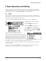
4 Basic Operation and Editing ......................................................... 27
4.1 Presets ................................................................................................... 27
4.2 The Grid ................................................................................................. 28
4.2.1
4.2.2
4.2.3
4.2.4
4.2.5
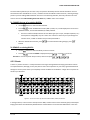
Inserting and Removing Blocks ............................................................................................................28
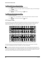
Shunts ..................................................................................................................................................29
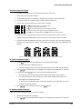
Connector Cables .................................................................................................................................30
Moving Blocks on the Grid ...................................................................................................................32
Example Presets on the Grid ................................................................................................................33
4.3 Editing Sounds ....................................................................................... 35
4.3.1
Quick Control .......................................................................................................................................36
4.4 X/Y Switching ......................................................................................... 36
4.4.1
X/Y Quick Jump ....................................................................................................................................37
4.5 Bypassing a Block ................................................................................... 37
4.6 Loading Effects from another Preset ...................................................... 37
4.7 Saving Changes ...................................................................................... 38
4.7.1
Swapping the Locations of Two Presets ..............................................................................................38
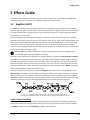
5 Effects Guide ............................................................................... 39
5.1 Amplifier [AMP] ..................................................................................... 39
5.1.1
5.1.2
5.1.3
5.1.4
Basic Amp Parameters (TYPE, PRE, PWR, EQ Pages) ...........................................................................40
Amp Speaker Parameters ....................................................................................................................42
Amp Dynamics Parameters ..................................................................................................................43
Advanced Amp Parameters .................................................................................................................44
5.2 Cabinet [CAB] ......................................................................................... 48
5.2.1
User Cabs .............................................................................................................................................50
5.3 Chorus [CHO] ......................................................................................... 51
5.4 Compressor [CMP] ................................................................................. 53
5.5 Crossover [XVR] ..................................................................................... 55
5.6 Delay [DLY] ............................................................................................ 56
5.6.1
5.6.2
5.6.3
5.6.4
5.6.5
Doc v15.0b
Mono Delay..........................................................................................................................................57
Stereo Delay .........................................................................................................................................58
Dual Delay ............................................................................................................................................59
Ping-Pong Delay ...................................................................................................................................60
Sweep Delay.........................................................................................................................................60
v
TABLE OF CONTENTS
5.6.6
5.6.7
5.6.8
Reverse Delay ......................................................................................................................................60
Tape Delay ...........................................................................................................................................61
Delay Common Parameters .................................................................................................................62
5.7 Drive [DRV] ............................................................................................ 64
5.8 Effects Loop [FXL] ................................................................................... 66
5.9 Enhancer [ENH] ...................................................................................... 67
5.10
Feedback Send [SND] & Return [RTN].................................................. 68
5.11
Filter [FLT] ........................................................................................... 68
5.12
Flanger [FLG] ....................................................................................... 69
5.13
Formant [FRM] .................................................................................... 71
5.14
Gate/Expander [GTE]........................................................................... 72
5.15
Graphic Equalizer [GEQ] ...................................................................... 73
5.16
Looper [LPR] ........................................................................................ 73
5.17
Megatap Delay [MGT] ......................................................................... 75
5.18
Mixer [MIX] ......................................................................................... 76
5.19
Multiband Compressor [MBC] ............................................................. 77
5.20
Multi-Delay [MTD] .............................................................................. 78
5.20.1
5.20.2
5.20.3
5.20.4
5.20.5
5.20.6
5.20.7
5.20.8
5.20.9
5.20.10
5.21
Tremolo/Panner [PAN] ........................................................................ 86
5.22
Parametric EQ [PEQ]............................................................................ 87
5.23
Phaser [PHA] ....................................................................................... 89
5.24
Pitch Shifter [PIT] ................................................................................ 91
5.24.1
5.24.2
vi
Quad Tap Delay ....................................................................................................................................79
Plex Delay .............................................................................................................................................80
Plex Detune ..........................................................................................................................................82
Plex Shift ..............................................................................................................................................82
Band Delay ...........................................................................................................................................83
Quad Series Delay ................................................................................................................................83
Ten-Tap Delay ......................................................................................................................................84
Rhythm Tap Delay ................................................................................................................................85
Diffusor ................................................................................................................................................86
Quad Tape Delay ..............................................................................................................................86
Detune .................................................................................................................................................93
Fixed Harmony .....................................................................................................................................93
Doc v15.0b
TABLE OF CONTENTS
5.24.3
5.24.4
5.24.5
5.24.6
5.24.7
5.24.8
5.24.9
Intelligent Harmony .............................................................................................................................94
Classic Whammy ..................................................................................................................................97
Octave Divider .....................................................................................................................................97
Crystals .................................................................................................................................................98
Advanced Whammy .............................................................................................................................99
Arpeggiator ........................................................................................................................................100
Custom Shifter ...................................................................................................................................101
5.25
Quad Chorus [QCH] ........................................................................... 102
5.26
Resonator [RES]................................................................................. 104
5.27
Reverb [REV] ..................................................................................... 105
5.28
Ring Modulator [RNG] ....................................................................... 107
5.29
Rotary Speaker [ROT] ........................................................................ 108
5.30
Synth [SYN] ....................................................................................... 109
5.31
Tone Matching [TMA]........................................................................ 110
5.32
Vocoder [VOC]................................................................................... 111
5.33
Volume/Pan [VOL] ............................................................................ 112
5.34
Wahwah [WAH] ................................................................................ 113
5.35
Input Noise Gate ............................................................................... 114
5.35.1
Input Impedance ................................................................................................................................114
5.36
Output Mixer .................................................................................... 115
5.37
Common Mix Parameters .................................................................. 116
6 Global Blocks............................................................................. 118
6.1 Introduction ......................................................................................... 118
6.2 Using Global Blocks .............................................................................. 118
6.2.1
6.2.2
6.2.3
6.2.4
6.2.5
Saving to a Global Block .....................................................................................................................119
Loading and Linking a Global Block ....................................................................................................120
Loading Global Blocks without Linking ..............................................................................................120
Unlinking Preset and Global Blocks ...................................................................................................121
Backing Up/Sharing Presets Containing Global Blocks ......................................................................122
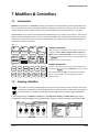
7 Modifiers & Controllers ............................................................. 123
7.1 Introduction ......................................................................................... 123
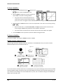
7.2 Creating a Modifier .............................................................................. 123
Doc v15.0b
vii
TABLE OF CONTENTS
7.2.1
7.2.2
7.2.3
7.2.4
7.2.5
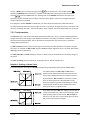
Transformations.................................................................................................................................125
Scale and Offset .................................................................................................................................126
Damping .............................................................................................................................................127
Auto Engage .......................................................................................................................................127
Program Change Reset ......................................................................................................................128
7.3 Control Sources .................................................................................... 128
7.3.1
7.3.2
7.3.3
7.3.4
7.3.5
7.3.6
7.3.7
7.3.8
LFO1 & 2 ............................................................................................................................................128
ADSR 1 & 2 .........................................................................................................................................129
Sequencer ..........................................................................................................................................130
Envelope Follower .............................................................................................................................130
Pitch Detector ....................................................................................................................................131
Manual Knobs ....................................................................................................................................131
Scene Controllers ...............................................................................................................................131
External Controllers ...........................................................................................................................131
8 Global Parameters..................................................................... 132
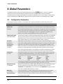
8.1 Configuration Parameters .................................................................... 132
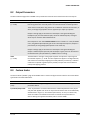
8.2 Output Parameters .............................................................................. 133
8.3 Custom Scales ...................................................................................... 133
9 Input/Output Parameters .......................................................... 134
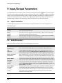
9.1 Input Parameters ................................................................................. 134
9.2 Audio Parameters ................................................................................ 134
9.3 MIDI Parameters .................................................................................. 136
9.4 Control Parameters .............................................................................. 138
9.5 Pedal Parameters ................................................................................. 140
9.6 X/Y Quick-Jump Assign ......................................................................... 140
10 Utilities ................................................................................... 141
10.1
LCD Contrast...................................................................................... 141
10.2
Preset Utilities ................................................................................... 141
10.3
Status Meters .................................................................................... 141
10.4
Reset System ..................................................................................... 142
10.5
IR Capture ......................................................................................... 142
10.6
Firmware ........................................................................................... 144
viii
Doc v15.0b
TABLE OF CONTENTS
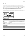
11 Tuner ...................................................................................... 145
12 Tempo .................................................................................... 146
12.1
Setting the Tempo ............................................................................. 146
12.2
Synchronizing Sound Parameters ...................................................... 146
12.3
Tempo to Use .................................................................................... 147
12.4
Auto Delay ........................................................................................ 147
12.5
Metronome ....................................................................................... 147
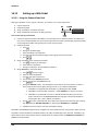
13 Backing Up and Restoring ........................................................ 148
13.1
13.1.1
13.1.2
MIDI/SysEx Backup and Restore ........................................................ 148
Dumping to a computer .....................................................................................................................148
Restoring from a Computer ...............................................................................................................149
13.2
Onboard ROM Backup and Restore ................................................... 149
13.3
Machine-to-Machine Transfers.......................................................... 150
14 Firmware Updates................................................................... 151
14.1.1
Axe-Fx II XL Failsafe Firmware............................................................................................................151
15 Troubleshooting ...................................................................... 152
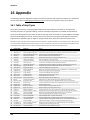
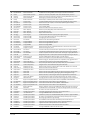
16 Appendix ................................................................................ 154
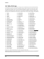
16.1
Table of Amp Types ........................................................................... 154
16.2
Table of Cab Types ............................................................................ 158
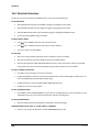
16.3
Loading User Cab IRs ......................................................................... 159
16.4
Shortcuts Overview ........................................................................... 160
16.5
60-Second Edit Guide ........................................................................ 161
16.6
Understanding Preset Size Limits ....................................................... 162
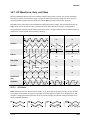
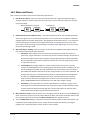
16.7
LFO Waveforms, Duty, and Phase ...................................................... 163
16.7.1
LFO Phase...........................................................................................................................................163
16.8
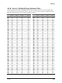
Tempo Cross Reference ..................................................................... 164
16.9
Mono and Stereo............................................................................... 165
16.10
Mixology......................................................................................... 166
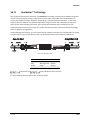
16.11
Humbuster™ Technology ................................................................ 167
Doc v15.0b
ix
TABLE OF CONTENTS
16.12
Setting up a Wah Pedal ................................................................... 168
16.12.1
16.12.2
16.13
Using the Onboard Pedal Jack .......................................................................................................168
Using an Expression Pedal on an MFC-101 ....................................................................................169
Setting Up Spillover ........................................................................ 170
16.13.1
16.13.2
16.14
Within a Single Preset ....................................................................................................................170
Across Different Presets.................................................................................................................170
Using Send and Return ................................................................... 171
16.14.1
16.14.2
16.15
Creating Feedback Loops ..............................................................................................................171
Extending the Length of Effect Chains ...........................................................................................172
Scenes ............................................................................................ 173
16.15.1
16.15.2
16.15.3
16.15.4
16.15.5
16.15.6
16.15.7
Selecting Scenes .............................................................................................................................174
SETTING UP SCENES .......................................................................................................................174
SAVING SCENES ..............................................................................................................................174
SPILLOVER IN SCENES ....................................................................................................................175
SCENES AND MIDI ..........................................................................................................................175
MFC-101 Scene Features ...............................................................................................................176
Table of CC# Values for Scene Select .............................................................................................176
16.16
Modifier Power! ............................................................................. 177
16.17
Glossary & Resources ..................................................................... 178
16.18
Axe-Fx II XL Bank & Preset Numbers Table ...................................... 181
16.19
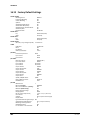
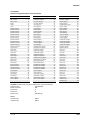
Factory Default Settings .................................................................. 182
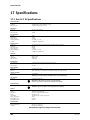
17 Specifications .......................................................................... 184
17.1
Axe-Fx II XL Specifications ................................................................. 184
17.2
Axe-Fx II Mark II Specifications .......................................................... 185
17.3
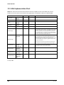
Midi Implementation Chart ............................................................... 186
Warranty ....................................................................................... 187
End User License Agreement .......................................................... 188
x
Doc v15.0b
WHAT’S NEW
What’s New
Years of R&D at Fractal Audio Systems have yielded our next-generation product, the Axe-Fx II. With twice the
power of our former flagship the Ultra, the Axe-Fx II unveils new state-of-the-art algorithms and an innovative
array of great hardware and software features and improvements. This all-in-one preamp/effects processor
stunningly recreates complete signal chains—stompboxes, amps, cabs, mics, studio effects, and more—with
unprecedented power, flexibility, and control. The Axe-Fx II takes "real amp tone and feel" to the next level,
offering the latest word on restoring digital to its rightful place as the superior solution for guitar processing.
Twice the Processing Power
Our philosophy is never to cut corners on processing power. Our new state-of-the-art algorithms required a
powerful platform on which to operate, so the Axe-Fx II features two 600 MHz dual-core Analog Devices
TigerSHARC™ Digital Signal Processors working in tandem. One is devoted solely to amp modeling while the other
handles effects and system tasks. Mated to the processors is double the RAM of previous Axe-Fx products. The
Axe-Fx II is by far the most powerful instrument processor ever created, with more raw, real-time audio processing
horsepower than anything available at any price. Yet, unlike power-hungry PCs, it consumes less than 40W.
G2 Amp Modeling™ with Virtual Vacuum Tube™ Technology and MIMIC™
All this power would be useless without superior algorithms to take advantage of it. Years of research have yielded
our G2 Amp Modeling Technology, comprising major breakthroughs in both preamp and power amp modeling.
First, we created our new Virtual Vacuum Tube technology, or VVT. VVT is a complete departure from the static
waveshaping technology used by other products. It is a digital replica of a vacuum tube, complete with time,
frequency, and level dependencies. This creates a level of dynamic realism in a class of its own.
Next, we rewrote the book on power amp modeling. G2 models the entire power amp, including the phase
inverter, power tubes, output transformer, power transformer, choke, filter caps, and more. The results are
amazing: tight bass, powerful midrange, silky highs, plus highly expressive touch sensitivity.
Our amp models are the result of thousands of hours of incredibly detailed analysis of the actual amps that
inspired them. We spent a small fortune searching out and purchasing vintage and modern amplifiers to add to our
reference collection. Multi-point Iterative Matching and Impedance Correction (MIMIC™) technology is a
significant advancement in amplifier simulation unmatched by any other product at any price point.
Improved Speaker Simulation, On-board IR Capture and UltraRes™
The Axe-Fx II cabinet simulator supports both High-Res (2048) and UltraRes™ formats, with 150+* factory Impulse
Responses (IRs) — including creations by Fractal Audio Systems, RedWirez, OwnHammer, Kalthallen, Jay Mitchell,
James Santiago, TheAmpFactory, and John Petrucci of Dream Theater — plus 512* "USER CAB" memory locations
and built-in tools to create your own Axe-Fx II User Cab IRs from a real speaker cab. UltraRes™ is a proprietary
technique that enhances the spectral resolution of an IR without adding CPU burden or storage requirements.
Tone Matching to “Clone” any Tone
The Axe-Fx II features a Tone Matching block with the capability to match the sound of a real or recorded amp. It
does this by analyzing the difference between the sound of your preset (the “local” signal) and a “reference”
(usually the signal from one or more mics/preamps on a real amp, or a high quality recording.) Tone matching
eliminates guesswork to create exact “clones” of your favorite tone. A separate Tone Match Mini-manual is
provided.
*The Axe-Fx II Mark 2 has only 130+ factory IRs and 100 user IR slots.
Doc v15.0b
1
WHAT’S NEW
Easier-to-Use Front Panel Features
A new, custom-designed 160x80 backlit LCD provides improved readability and more spacious screen layouts. In
addition to the main VALUE knob, new QUICK CONTROL knobs provide hands-on access to four additional onscreen parameters. Ten block types—Amp, Cab, Chorus, Drive, Delay, Flanger, Phaser, Pitch, Reverb, and
Wahwah—are now equipped with two fully independent parameter sets called “X” and “Y.” The X/Y switching
feature allows one block to have all of its settings switched at the touch of a button (during editing) or via MIDI
remote control (during performance). The X and Y buttons also double as user-definable “quick jump” keys that
can be set up to open the EDIT menus of any two blocks without going through the grid. A built in FLASH ROM
enables onboard backups of preset banks and system settings.
Axe-Fx II/Computer Integration with Onboard USB
The new onboard Audio Class 2.0 compliant USB interface provides great capabilities for recording and computer
integration. You can record high quality 48k/24-bit audio from the Axe-Fx II directly to the computer, play or
rd
process audio tracks from the computer through the Axe-Fx II, and use two-way high-speed MIDI without a 3 party interface. On USB 2.0 or better systems, you can simultaneously record both the main processed stereo outs
and a pair of dry channels for easy re-amping.
New I/O Capabilities and Less Noise
All rear analog inputs are now balanced like the onboard XLR outputs. The ¼" unbalanced outputs feature our
Humbuster™ technology, which senses and subtracts the ground noise of equipment connected with a simple
stereo-to-mono cable. This can provide up to 20 dB reduction in ground noise without resorting to dangerous
"cheater plugs" or expensive isolation transformers.
We designed the Axe-Fx II with the “Four-Cable Method” in mind. Special analog processing keeps the noise floor
even lower on outputs designed to be connected to the front of an amplifier.
The front panel input uses a proprietary circuit and dedicated A/D converter for astonishingly low noise. The
original Axe-Fx was hailed for its low-noise performance; the Axe-Fx II provides an almost 10 dB SNR improvement
with the same pristine quality. A high-quality headphone jack is also provided.
Designed for Unity Gain
The Axe-Fx II uses digitally controlled potentiometers to operate as a unity-gain device irrespective of the input
trim controls. Simply set the input trims with the LED input meters and you are done. Another benefit of this
technique is that Amp and Drive blocks are unaffected by trim settings.
Improved Digital I/O
In addition to its USB interface, the Axe-Fx II sports SPDIF and AES input and output connectors. 7-pin MIDI In and a
selectable MIDI Out/Thru jack are provided for interconnection with other MIDI-controllable equipment.
Built for MFC-101 and FASLINK™
Both the XL and the Axe-Fx II Mark II feature an EtherCON port for connecting an MFC-101 MIDI Foot Controller
via network cables (the original Axe-Fx II has an Ethernet port only). The Axe-Fx II XL also features an onboard
FASLINK™ port for connecting an MFC-101 Mark III over a standard XLR cable. FASLINK™ carries power (without
the need for a wall-wart) and bi-directional communication between the two units. Don’t worry if you own an
MFC-101 original or Mark II—an optional FASLINK™ adapter allows you to use this new connection standard. A
rd
MIDI port for use with 7-pin phantom power or 5-pin MIDI cables (for connecting 3 party MIDI interfaces or
pedalboards, for example) is also provided.
2
Doc v15.0b
WHAT’S NEW
New FX Processing Features and Enhancements
The effects-processing capabilities of the Axe-Fx II have been vetted and endorsed by some of the most
discriminating players in the world. The sound and features of our effects provide extremely authentic
representations of many classic originals, plus the range to take you where no tone has gone before. Now, with a
TYPE control to instantly set all other parameters, it is easier than ever to dial in classic settings on many effect
blocks. “Types” include tape and analog "bucket brigade" delay effects, “script" and "block" logo phasers,
“dimension” chorus, jet flanger, vibe phaser, many classic wah pedals, whammy, and too many more to list here.
Share Settings Across Multiple Presets with Global Blocks
Those familiar with “Global Amps” from previous Axe-Fx products will appreciate Global Blocks. Those new to AxeFx products will appreciate how this feature allows centralized control of a preset collection. You can save any
effect “block” to a special memory area, then load it into multiple presets with a "link" to keep all copies
synchronized to the master. You can even update the master from any linked instance. Should you choose to
remove a link, this leaves both the original and the new copy fully independent of each other.
Axe-Fx II XL New Features
This manual covers both the Axe-Fx II Mark II and the newer Axe-Fx II XL. Both units have the same DSP and amp
modeling capabilities, but the XL offers the additions of expanded memory and peripherals as detailed below:
Built-in FASLINK™ port for connection to MFC-101 Mark III over conventional XLR cables.
Dedicated MIDI IN, OUT, and THRU jacks (vs. shared OUT/THRU in the Mark II).
Two onboard PEDAL jacks (vs. one in the Mark II).
Primary VALUE entry via optical encoder with a lifespan of 1,000,000+ rotations.
“Secret Sauce III” instrument input features an even lower noise floor.
128 Mb of non-volatile Super-FLASH memory allows for storing 512 presets and 512 user cabinets, plus
copious memory reserves for future expansion.
Double-capacity preset size allows for expanded functionality including X/Y switching on more blocks and
possible future implementation of more effect instances per preset.
Built-in backup firmware allows recovery in the event of complications during update.
Backward compatibility with Axe-Fx II Mark I/II presets via Axe-Edit software.
Improvements and Enhancements, plus More to Come...
Aside from the many features covered in this brief introduction, there are many more things in the Axe-Fx II that
we hope will make it one of the most exciting and rewarding products you have ever owned. The upgradeable
firmware of our products means that the best is always yet to come, with free updates released regularly in the
form of easy-to-install downloads.
Doc v15.0b
3
INTRODUCTION
1 Introduction
1.1 What is the Axe FX II?
The Axe-Fx II is an advanced digital preamp and effects processor for guitar, bass, and other musical instruments. It
replaces amps, speakers, microphones, stompboxes, studio processors, and more. It is an all-in-one, end-to-end
great tone solution in a single black box.
Inside, a virtual environment allows you to build your dream rig (hundreds of them, in fact). Choose from an
inventory of hundreds of classic and innovative components. Select and arrange things any way you like, limited
only by the unit’s ample CPU resources and your imagination. “Dial in” your signature sound using basic controls,
or go deeper with advanced parameters, then save presets for instant recall when playing, performing, or
recording.
The sound is of uncompromising quality, due both to extremely high standards of hardware design and to our
advanced proprietary software algorithms. The Axe-Fx II, like its predecessors, asserts that digital has reclaimed its
birthright as the superior solution for musical instrument processing. Words fall short. You only need to plug in and
play to realize that this is “the real deal.”
A Word on Modeling
You may have noticed that the Axe-Fx II is not typically described as a “modeler.” This is not to diminish its debt to
heritage; on the contrary, we’ve done thousands of hours of deep analysis of the greatest amps, cabs, and effects
of all time. In fact, amps and pedals, their vacuum tubes and other components, plus speaker cabs and many
effects, are painstakingly replicated to perform exactly like the originals. But while the unit includes emulations
based on specific product types, it goes well beyond simply presenting models—with their limited controls,
features, and sounds—to offer a do-it-yourself modeling platform. If it’s models you want, we can give them to
you, but why stop there?
The Axe-Fx II removes limits instead of recreating them. Take our Wahwah effect, for example. You might just plug
in and start cryin’, or you could tune the pedal sweep, tweak the resonance, overdrive the circuit, and tailor the
sound to your exact wishes. Try the Plexi. Dial it in just right. Then open things up and hear what happens when
you drop in the tonestack from a modern Rectifier (all it takes is one turn of a knob to make the change). There are
hundreds more ways that the sound can be customized. Rediscover your all-time favorites, or go crazy creating
sounds you only wished someone would put in a product. And you don’t need to be an engineer to do so, as the
unit is extremely user-friendly.
You are not alone in the quest for tone, either. The Fractal Audio online community has amassed a wealth of
knowledge and is ready to share expertise on every subject, from the deviling details of differently dated diodes in
dilapidated distortions to how to set up your favorite artist’s “exact gear used in the exact order with the exact
settings for the first half of the second bridge of the third bonus track off the re-master.”
In comparison to its predecessors, the Axe-Fx II has some great new capabilities as an effects modeler. Just as our
previous products allowed you to select, for instance, a “TYPE” of Amp, Cab, or Drive, now the Chorus, Delay,
Flanger, Phaser and other effects include a control to automatically dial in all-time favorites—settings like
4
Doc v15.0b
INTRODUCTION
“dimension chorus”, “tape delay”, “analog flanger”, “script 90 phaser”, and many more. Once you make a
selection, however, you can go beyond the model. With deep recreations of the intricacies and interactions behind
great tone, we create not only a sample or profile but a multidimensional whole enchilada. Again, just plug in and
hear it for yourself.
To re-pose the original question then, what is the Axe-Fx II?
The Axe-Fx II is the new flagship processor from Fractal Audio, with far more power and many more capabilities
than the former heavyweight champion, Axe-Fx Ultra—twice the DSP in fact, allowing it to deliver far more
detailed amp modeling, plus numerous other upgrades. It contains our best-ever guitar amplifier simulation and
effect technology—state-of-the-art algorithms designed to sound and feel like the real thing. It is a fully routable,
fully programmable, real-time controllable, multi-effects processor offering the utmost in sound quality, with
unrivaled flexibility and control options. It is a modeling platform upon which you can create any number of
incredible guitar tones—able to replace entire rigs of traditional gear with a single black box. Let’s take some of
these concepts a bit further:
Routable: Place effects freely in any order and layout—series, parallel, or complex networks, including feedback
loops and external send and return, at any point in the signal chain.
Programmable: Every effect has a full complement of parameters offering desirable features and tremendous
range. Gone are the limits of processors with restrictive options or little-to-no depth.
Controllable: Many parameters—including all the usual expression pedal suspects and every effect bypass
switch—can be operated remotely via MIDI, offering great real-time performance control capabilities. You can map
control curves, assign multiple parameters at once, tap powerful global controllers, and much more.
Multi-Fx: The Axe-Fx II offers all the classic effects plus a few new ones. The massive “effects inventory” allows any
preset to use two or more of almost every effect block type, so you can build huge virtual rigs. In addition, many
effects now include X/Y states so you can instantly swap one set of settings for another without changing presets.
Almost all the effects in the Axe-Fx II process in full stereo.
Utmost Quality: Sound quality is our first-and-foremost criterion for the success of the Axe-Fx II. This shows in the
hardware design and in every detail of our proprietary natural processing software algorithms. Many of these
replicate patterns that occur in nature (thus our company name of Fractal Audio Systems). The amp simulations
use unique, dynamic, non-linearity generators that produce smooth, even-ordered harmonics, giving a depth to
the sound that other processors lack. Our effects have been vetted and championed by some of the world’s most
demanding and discriminating players.
Rig Replacer: Having everything in one box has some great advantages, especially when that box is as powerful
and versatile as the Axe-Fx II. In addition to being able to replace big rigs outright, this tightly integrated, unified
system offers certain fringe benefits. No longer does changing a drive pedal mean fighting with cables half-an-inch
too short. No longer must you labor over deciding which amps your tour’s budget will or won’t allow you to ship or
handle. Gone are the headaches and hassles of systems of so many boxes strung together with so many wires,
prone as they are to failure and noise. And let’s say a small meteor hits the stage and obliterates your Axe-Fx II:
you can literally restore to a new unit during the intermission and be up and running again for the next set.
Finally, after you’ve replaced your entire rig, the Axe-Fx II lets you continually re-invent it without ever touching
Velcro, rack screws, or your credit card.
Doc v15.0b
5
INTRODUCTION
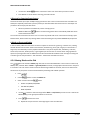
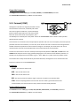
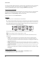
1.2 The Inventory/Grid Concept
In the real world, we are limited by the equipment we own and by the fact that building a rig requires making
commitments. On the Axe-Fx II, these limitations are lifted, with the ability to tap a vast inventory of virtual amps,
cabs, effects, mixers, and more. You have the freedom to set them up, dial them in, save them as presets, and then
do it all again, as often as you like.
Axe-Fx II presets are created by selecting components—like amps, cabs, or effects—from an inventory, and placing
them as “blocks” into the slots of a 12×4 “grid.” As with their real-world components, blocks must be connected
together using “cables”—virtual ones in this case. Blocks in adjacent columns may be connected directly together,
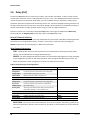
with splits and merges as needed. Passive “shunts” carry signal through otherwise empty grid spaces.
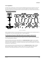
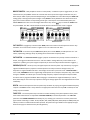
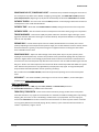
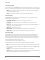
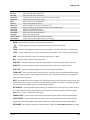
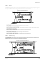
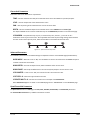
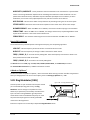
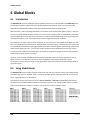
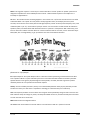
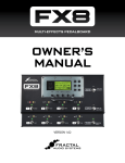
Figure 1-1 – The Inventory/Grid Concept
(Note: Seven empty columns were removed from the illustration and are represented by •••)
The figure above presents a stylized example of an Axe-Fx II preset. The INPUT is routed through a SHUNT to feed a
“WAH” block. (The shunt has no effect on the sound and is shown only to introduce the concept of its use.) The
WAH block is connected to an “AMP” block (we might set its type to “Plexi Normal”), which in turn feeds a “CAB”
(one of the many “4x12” options, perhaps). This is routed to a reverb (“REV”) and then to the OUTPUT.
The size of a preset is limited only by the grid structure, block inventory, and total processing power or “CPU”.
You’ll be pleased to discover that there is enough CPU power to allow large and complex creations.
6
Doc v15.0b
INTRODUCTION
The subject of creating and modifying presets on the grid is covered in detail in section 4: Basic Operation and
Editing (p.27). The inventory of blocks available to every Axe-Fx II preset is listed below:
Amp (×2)
Cab (×2)
Chorus (×2)
Compressor (×2)
Crossover (×2)
Delay (×2)
Drive (×2)
Effects Loop
Enhancer
Filter (×4)
Feedback Return
Feedback Send
Flanger (×2)
Formant
Gate/Expander (×2)
Graphic EQ (×4)
Looper
Megatap Delay
Mixer (×2)
Multiband Compressor (×2)
Multi-Delay (×2)
Tremolo/Panner (×2)
Parametric EQ (×4)
Phaser (×2)
Pitch Shifter (×2)
Quad Chorus (×2)
Resonator (×2)
Reverb (×2)
Ring Modulator
Rotary (×2)
3-Voice Synth (×2)
Tone Matching
Vocoder
Volume/Pan (×4)
Wahwah (×2)
Shunt (36)
In addition to the blocks listed above, each preset also includes a programmable Input Noise Gate (p. 114) and an
Output Mixer (p. 115). Of course, having components on the grid is just the beginning. Every block can be edited,
with parameters representing all the basic knobs you would expect to find, and advanced menus for deep control.
See the Effects Guide (p. 39) for more detail on blocks and their parameters.
A powerful new feature of the Axe-Fx II allows you to maintain your own collection of Global Blocks (p.118) that
can be inserted and then kept synchronized across multiple presets.
Twenty-two different Modifiers & Controllers (p. 123) are provided to automate or remotely control various
parameters in any preset. These are LFO 1, LFO 2, ADSR 1, ADSR 2, Envelope, Pitch Detector, Sequencer, Manual
A/B/C/D, and External 1–12.
1.3 Connectivity and More
The grid and effects inventory may be the centerpiece of the Axe-Fx II, but it is the powerful connectivity and
companion features that allow the system to be so much to so many. The hardware itself is covered in Section 2:
Overview (p. 8), which also details the new USB features for Computer Integration (p. 12). Rig design is covered in
Section 3: Connections (p. 15), where many diagrams are included.
Configuration and connectivity on the Axe-Fx II are managed with a number of user-specifiable options, listed and
described in Section 8: Global Parameters (p. 132), and Section 9: Input/Output Parameters (p. 134). Meanwhile,
Section 10: Utilities (p. 141) can fill out your understanding of functions related to general use and maintenance.
Finally, Sections 11 through 14 cover the Tuner (p. 145) and Tempo (p.146) functions, plus the basics of Backing
Up and Restoring (p. 148) and Firmware Updates (p. 151).
1.3.1 My Head Hertz…
As even this brief introduction demonstrates, the Axe-Fx II contains an entire world of diverse possibilities. Only
the precise terminology of audio engineering allows comparably diverse communities of casual and professional
players, producers, engineers, and others to use and enjoy this powerful device. In case you want to familiarize
yourself with specific audio terms or come up to speed on other topics, the Appendix is filled with useful material,
including a Glossary (p. 173). It is followed by Specifications (p. 187) and your Warranty (p. 184).
Doc v15.0b
7
OVERVIEW
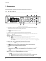
2 Overview
Review the following to familiarize yourself with the hardware features of the Axe-Fx II.
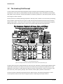
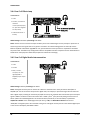
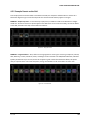
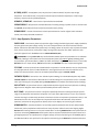
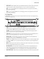
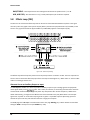
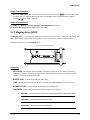
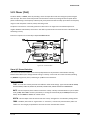
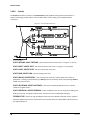
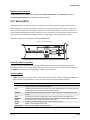
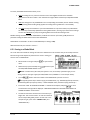
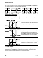
2.1 The Front Panel
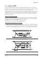
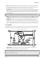
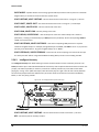
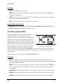
The front panel shown is that of the Axe-Fx II XL. It is functionally identical to that of the Axe-Fx II Mark II.
Figure 2-1 – The Axe-Fx II Front Panel
1. The Axe-Fx II is housed in a powder-coated steel enclosure with an anodized aluminum faceplate.
Dual front handles allow easy rack mounting and removal.
2. The
Switch turns the unit on or off.
3. The 160 × 80 pixel LCD is where all menu and function screens are displayed.
4.
and
5.
LED meters display the levels of incoming signals. See p. 15 for more detail.
LEDs communicate important events:
– This LED is lit when any change has been made to the current preset.
– This LED is lit while data is received at the MIDI IN port.
,
– These flash briefly whenever the signal level at the corresponding output
causes the D/A converter to clip. Section 3.1 on p. 15 has more information on Setting Levels.
6. In RECALL mode, the
wheel selects and loads presets as it is turned.
In edit or menu screens, it changes the value of the selected parameter.
7. The
button executes commands, commits changes, accesses sub-menus, and more.
works for cancel, escape, and various other functions.
8. In RECALL mode, the four
buttons select and load presets. Up = +1; Down = -1; Left=-10; Right =+10.
In edit or menu screens, these are used to select between on-screen parameters or options.
9. The
buttons step through menu pages, shown as tabs at the top of the display.
10. The 12 main front panel menu/function buttons are listed below.
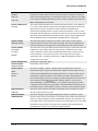
– This menu contains four pages: EDIT, MOVE, GATE, and MIX.
8
EDIT contains the grid where presets are created by inserting blocks and cables (p. 27).
MOVE has various utilities for moving preset components on the grid (p. 32).
Doc v15.0b
OVERVIEW
INPUT/GTE contains parameters for the Noise Gate and Instrument input impedance (p. 114).
OUTPUT page contains a mixer for overall level control of a preset (p. 115).
– Select any block on the layout grid and press this button to open its EDIT menu.
Press repeatedly to cycle through EDIT menus of all blocks in the preset (top-to-bottom, left-to-right).
– This menu contains pages for seven of the internal controllers available to every preset,
plus a Modifiers overview screen. See Modifiers & Controllers on p. 123 for details.
– This button toggles the bypass state of the currently selected block (p. 37).
Double click BYPASS in any block EDIT menu to access SAVE/LOAD GLOBAL BLOCKS (p. 118).
– This menu contains four pages: CONFIG, OUT1, OUT2, and SCALES. See p. 132 for details.
CONFIG contains parameters that globally affect the sound of all presets.
OUT1 and OUT2 each hold a 10-band graphic EQ and master GAIN control for the given outputs.
SCALES allows the creation of custom harmonies for use with the pitch shifter block.
– Engages the tuner (p. 145) and displays its menu. Press
or
to close.
– Contains six pages used to configure the various input and output options of the Axe-Fx II.
See p. 134 for details.
– This menu contains various utility functions. See p. 141 for details.
– Enters RECALL mode, the main operating mode for use during musical performance.
The Axe-Fx II always defaults to RECALL mode when you power it on.
– Enters the STORE menu where you can save, rename, or swap presets. See p. 37 for details.
– Bypasses the Axe-Fx II, routing the input directly to the output, defeating all processing,
lighting the BYPASS LED and showing a flashing on-screen warning. Press again to un-bypass.
Double-clicking the BYPASS button in any block EDIT menu initializes that block to default settings.
– Flashes the current tempo on its built-in LED. You can also tap this button once to enter the
TEMPO menu, or two or more times to set a new tempo. The tempo can also be entered using a
remote switch or set via MIDI. See p. 146 for more information about Axe-Fx II tempo control.
11.
– On the Axe-Fx II, certain effects offer two fully independent sets of settings, called “X” and “Y”.
Think of them like two different “channels” for a given amp or effect. You can switch between X and Y to
access different sound settings without changing presets (see p. 36).
and buttons perform other functions as well. See section 4.4 on p. 36
12.
– The four Quick Control knobs, A, B, C, and D, perform different functions depending
on what Axe-Fx II screen or menu is shown. See section 4.3.1 on p. 36 for more information.
13.
– These controls set the output levels of OUTPUT 1 and OUTPUT 2 (“FX Send”). See
section 3.1 on p. 15 for information on setting levels. OUTPUT 1 also controls headphone jack levels.
14.
15.
– Connect stereo headphones here to monitor OUTPUT 1 L+R.
– Plug your instrument into this Instrument Input Jack, designed specifically for use with electric,
acoustic, and bass guitars. Plugging a line-level device into this input may cause clipping of the input
amplifier and is not recommended.
The Axe-Fx II Mark II features “Secret Sauce II” instrument input for a low noise floor.
The Axe-Fx II XL features “Secret Sauce III” instrument input for an even lower noise floor.
Doc v15.0b
9
OVERVIEW
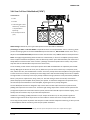
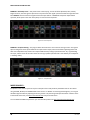
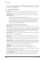
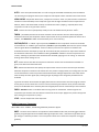
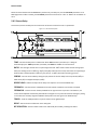
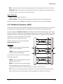
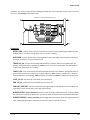
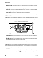
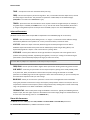
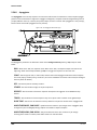
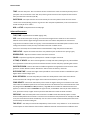
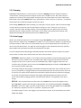
2.2 The Rear Panel
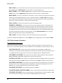
The following section details the rear panel of the Axe-Fx II. Please note differences between the Mark II and XL
models in numbered areas 22 (MIDI), 24 (MFC and FASLINK™) and 25 (PEDALS).
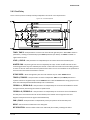
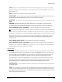
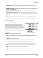
Figure 2-2 The Rear Panel of the Axe-Fx II XL
Figure 2-3 The Rear Panel of the Axe-Fx II Mark II
10
16.
Left/Mono and Right, Balanced (1/4” Tip-Ring-Sleeve) Jacks – Connect line-level input sources
to these jacks, being sure to set the INPUT 1 LEFT SELECT to REAR in the I/O menu (p. 134).
17.
– Left/Mono and Right, Balanced (1/4” Tip-Ring-Sleeve) Jacks (“
”) – Connect to the
output(s) of outboard equipment when using the FX Loop block (p. 66). You can also use this as an
auxiliary input to any point in the signal chain of any preset using the FX Loop block.
18.
– This section includes the Left and Right Output 1 unbalanced (1/4”) Jacks, Balanced (XLR)
jacks, and XLR Ground Lift Switch. The main processed output of the Axe-Fx II appears at these jacks. Use
the XLR jacks to connect to balanced inputs, employing the provided ground lift switch if necessary to
reduce unwanted 60-cycle hum. Use the 1/4” unbalanced outputs to connect to unbalanced inputs, such
as those on some guitar power amps or other devices.
19.
– Left/Mono and Right, Unbalanced (1/4” Tip-Sleeve) Jacks (“
”) — The output from
Connect to he inputs(s) of outboard equipment when using the FX Loop block (p. 66). You can also use
this as an auxiliary output to tap any point of the signal chain for any preset using the FX Loop block. New
Humbuster™ technology, featured on Left and Right Output 1 and Output 2 unbalanced (1/4”) Jacks
uses a simple TRS-to-TS cable to significantly reduce ground hum. See Section 16.11 on p. 167.
Doc v15.0b
OVERVIEW
20.
– This includes both S/PDIF and AES/EBU format Input and Output Jacks. Only one or the
other pair of jacks can be active at any time depending on the setting of the SPDIF/AES SELECT parameter
in the I/O:AUDIO menu (p. 134). These jacks transmit and receive at a fixed rate of 48k.
21.
– This provides the means to connect the Axe-Fx II to a PC or Mac, enabling a host of two-way audio
and MIDI capabilities. See section 2.3 on p.12. Like the digital i/o, USB Audio operates only at 48k.
22.
jacks – The Axe-Fx II XL has separate dedicated MIDI IN, MIDI OUT and MIDI THRU jacks.
Unlike a shared/soft MIDI THRU, the XL’s dedicated MIDI THRU jack adds no latency, but it is "hard-wired"
to the MIDI IN PORT, and therefore does not pass signals from other MIDI inputs. For THRU functionality
when using an MFC-101 at the FASLINK™ or MFC port of an Axe-Fx II XL, MIDI OUT can be made to work
as a soft THRU by setting MFC ECHO TO MIDI OUT to "ON" (on the MIDI page of the I/O menu).
The Axe-Fx II Mark II has a MIDI Out/Thru combo jack that transmits or forwards MIDI signals to another
device. MIDI THRU is disabled by default but can be enabled on the MIDI page of the I/O menu).
23.
Jack – When using the MFC-101 MIDI Foot Controller over a 7-pin MIDI cable,
connect the supplied AC Adapter to this jack to provide power to the floor unit via pins 6+7. Some other
MIDI controllers also support the use of phantom power on pins 6+7.
WARNING! Do not connect an AC adapter with a rating higher than 1A to the Phantom Power jack. Doing
so will damage your Axe-Fx II.
24.
Control Port – This RJ45 jack allows you to use a standard (non-crossover) CAT5/Ethernet cable to
connect the Axe-Fx II to a Fractal Audio Systems MFC-101 MIDI Foot Controller. The cable used to connect
the Axe-Fx II and MFC-101 carries two-way data communication and phantom power without needing an
external “wall wart” adapter. High quality Ethernet/EtherCON cables are available via
http://www.fractalaudio.com/cables. (Axe-Fx II “Original Version” supports only Ethernet, not EtherCON.)
WARNING! DO NOT connect the MFC jack to an Ethernet device such as a computer, hub, switch, or
router, as damage to one or both units could occur! Damage of this type leaves tell-tale signs on the
motherboard and is NOT covered under warranty.
Always ensure that the Axe-Fx II power is OFF before inserting/removing Ethernet/EtherCON cables.
Be careful not to insert other types of connectors such as USB or guitar cables into the MFC port of the
Axe-Fx II, as doing so can damage your unit, leaving tell-tale damage NOT covered under warranty.
The
connector of the Axe-Fx II XL allows you to connect to the FASLINK™ port of an MFC-101
Mark III. The standard XLR cable used for a FASLINK™ connection powers the MFC without an external
“wall wart” adapter, and carries 2-way communications. An optional XA-2 FASLINK™ Adapter allows you
to connect the Axe-Fx II XL to an earlier MFC-101.
The optional XA-1 FASLINK adapter adds a FASLINK port to the Axe-Fx II Mark II.
Find FASLINK™ adapters at http://shop.fractalaudio.com
25.
Jack – This jack is used to connect an external expression pedal or switch to control various
functions of the Axe-Fx II. See p. 16 for more information on this function.
26. Main Power Input – Insert the supplied power cable and connect the other end to a grounded AC power
receptacle.
Doc v15.0b
11
OVERVIEW
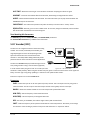
2.3 Computer Integration
USB provides every Axe-Fx II with a host of great features.
2.3.1 Minimum Requirements
Windows Minimum Requirements:
OS: Windows 8.x, Windows 7 SP1, Windows Vista SP2 (All versions compatible with x86 or x64).
CPU: Intel Core 2 @1.6 GHz or better, or AMD equivalent
Memory: 1GB minimum
USB 2.0 support required
Mac Minimum Requirements:
OS X: 10.6.8 for MIDI over USB (Fractal-Bot, Axe-Edit, Cab-Lab, etc.)
10.9 or later required for USB audio. An issue in older versions causes audio pops.
CPU: Intel Processor
Memory: 512MB minimum
USB 2.0 Support required
2.3.2 Software Installation
Although the Axe-Fx II is fully class-compliant, software installation is still required on all platforms. Without drivers
installed, USB capabilities will not work correctly. Both Mac and Windows versions can be downloaded from our
web site at http://www.fractalaudio.com/support. Step-by-step instructions are included with the installer.
12
Doc v15.0b
OVERVIEW
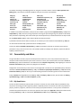
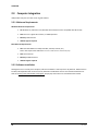
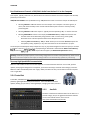
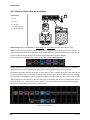
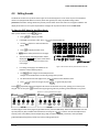
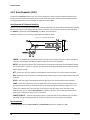
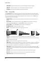
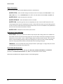
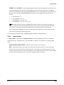
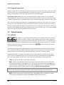
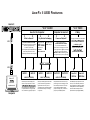
2.3.3 Capabilities
The USB 2.0 class-compliant driver provides two channels of 48k/24-bit audio from the computer to the Axe-Fx II,
up to four channels from the Axe-Fx II to the computer, and two-way MIDI-over-USB. All features can be used
simultaneously. Note that even though the Axe-Fx II is fully class-compliant, you must still install the drivers found
at http://fractalaudio.com/support .
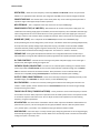
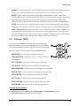
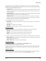
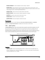
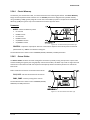
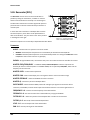
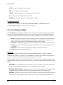
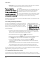
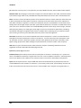
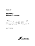
Figure 2-4 – USB Features
Audio and MIDI ports (shown in the top dotted-outline boxes above) have different names on different systems. In
many applications, you can also assign “friendly names” to audio and MIDI ports.
Two Simultaneous Channels of 48k/24-bit Audio from the Computer to the Axe-Fx II
Two output channels allow audio to be sent from the computer to the Axe-Fx II where it can be processed by the
unit or simply played back to OUTPUT 1.
To process computer audio with the onboard effects, set the MAIN INPUT SELECT (p. 134) to “USB.” Computer
audio will be routed to the grid INPUT. This allows you to re-amp a dry track, for example, or use the Axe-Fx II to
process other audio or plugin tracks. It is possible to simultaneously record the processed output on the computer
using the Axe-Fx II audio inputs (0/1).
To pass unprocessed computer audio through the Axe-Fx II, set the MAIN INPUT SELECT (p. 134) to “ANALOG
(IN1)” (the default setting) or “SPDIF/AES.” Computer audio is mixed with the regular output of the Axe-Fx,
allowing you to play along with backing tracks or use the Axe-Fx II as a high quality “soundcard.”
Doc v15.0b
13
OVERVIEW
Four Simultaneous Channels of 48k/24-bit Audio from the Axe-Fx II to the Computer
Four outputs, typically numbered 1–4, allow audio to be routed from the Axe-Fx II to the computer and recorded,
processed, or monitored.
USB/DIGI OUT SOURCE in the I/O:AUDIO menu (p. 134) determines what is sent to the first pair of USB outputs:
Selecting OUTPUT 1 L+R sends the Axe-Fx II main output to the computer. The same signal is, of
course, still routed normally to the rear XLR and unbalanced jacks. Use this to record your fullyprocessed guitar.
Selecting OUTPUT 2 L+R routes output 2—typically the FX loop block (p. 66) —to the first two outs.
Selecting MAIN INPUT routes the main input (see MAIN INPUT SELECT p. 134) to the first two outs.
A similar result can be obtained by using OUTPUT 1 with a “shunts-only” preset (p. 29).
Remember to turn off the Input Noise Gate and set Output levels to 0.0
Switching INPUT 1 LEFT SELECT (p. 134) to “REAR” allows you to record the line level outputs of a
microphone preamp, keyboard, or any other sound source via the rear INPUT 1 L/R jacks.
The second pair of USB Outputs always outputs the raw, dry, unprocessed signal from the main input (i.e. the front
jack or the rear
jack, depending on both what is selected under INPUT 1 LEFT SELECT (p.
134)) and the rear
jack). These require USB 2.0 support (see Minimum Requirements above).
Warning: As with all input/output systems, certain routing configurations can result in audio feedback loops. Please exercise
care not to route active outputs to active inputs, or damage could occur to connected amps, speakers, or your hearing.
Two-way High-Speed MIDI Communication
MIDI-over-USB enables the Axe-Fx II and the computer to communicate back and forth. You can edit, perform
updates, send program changes from a sequencer, synchronize the tempo, automate sound changes, and more.
MIDI-over-USB is considerably faster than “legacy” MIDI, and allows two-way communication with the computer
over a single cable.
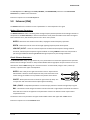
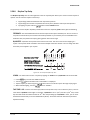
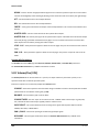
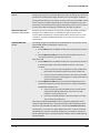
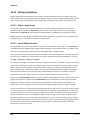
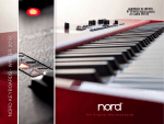
2.3.4 Fractal-Bot
Fractal-Bot, available from http://www.fractalaudio.com/fractal-bot.php is a
powerful, lightweight MIDI Utility for the Axe-Fx II. Use Fractal-Bot for firmware
updates, backing up your Axe-Fx, restoring backups, managing User Cabs, and more.
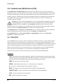
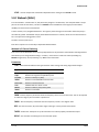
2.3.5
Axe-Edit
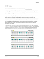
Axe-Edit is a full-featured software editor for the Axe-Fx II. It
provides a large, easy-to-use graphical interface that allows
you to create and edit sounds. Learn more at
http://www.fractalaudio.com/axe-edit
14
Doc v15.0b
CONNECTIONS
3 Connections
Before making connections, be sure to turn down the volume of your amps and switch off all power. Take
extreme care NEVER to connect the SPEAKER outputs of an amplifier to any jack on the Axe-Fx II as this will
damage one or both devices. If you’re not sure, don’t do it!
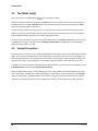
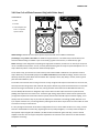
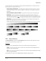
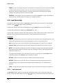
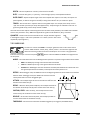
3.1 Setting Levels
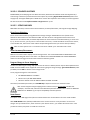
For the Axe-Fx II to work properly, it is important that input and
output levels be configured correctly.
INPUT LEVELS are set with “soft-knobs” on the INPUT page of the
I/O menu. Adjust according to the level of input source material
until “hot” signals “tickle” the red LEDs on the front panel INPUT
meters. The red LED lights at -6 dB (below clipping). Some sources
may not reach ideal levels but can still be used with no problems.
Changing input levels will NOT affect what you hear. Inputs are compensated, meaning that as you lower trims
to optimize signal-to-noise ratio going into the converters, the output of the converters is adjusted inversely
so “what you hear” (and what reaches the signal processor) always remains the same.
Each input has its own dedicated analog-to-digital converter. The
improved signal-to-noise performance.
input jack parallels the rear inputs for
The front panel
and knobs independently control the volumes at the corresponding rear
panel jacks. The output knob simultaneously controls
XLR and ¼-inch jacks, and the unit’s headphone
jack level. Optimal levels will depend on what the Axe-Fx II is connected to.
To operate with unity gain, set the Output Level knobs to maximum. If you then route shunts from the input to the
output you will get out exactly what you put in. (If you’re not using the Axe-Fx in the loop of a tube amp, unity gain
is likely not relevant.)
If levels result in clipping of attached equipment, turn down the front panel
minimum setting, volume is reduced but may not be silent.
knobs. At the
NOTE: The Axe-Fx II uses digital potentiometers to adjust the output levels. These actually contain hundreds of tiny resistors
and switches. As such, some noise may be generated while adjusting the knobs.
If the
or
LEDS light while you use the Axe-Fx II, the problem is not trim settings but levels in the
digital domain. Chances are that the effects in your preset—many of which can increase gain significantly—are
simply too hot. Reduce the output of one or more blocks (the AMP block OUTPUT LEVEL is usually a good starting
point) or adjust the main GAIN slider of the preset’s output mixer (see p. 115).
When you need to adjust the level of all of your presets at once because some are clipping, you can also use the
GAIN slider on the OUT1 or OUT2 graphic equalizers to make a global adjustment. (p. 133)
Clipping can also be caused if you have increased the BOOST/PAD setting for one of the converters and can be
reduced if you adjust this setting to be closer to 0 dB (see p. 134). Block or preset adjustment may still be required.
Doc v15.0b
15
CONNECTIONS
3.2 The PEDAL Jack(s)
Note: the Axe-Fx II XL has two onboard
jacks. The Mark II has one.
Connect an expression pedal or footswitch to the pedal jack to control sound functions. You must first configure
the TYPE, and perform a simple calibration routine when using an expression pedal. See section 9.5 on p.140 for
how to use the PEDAL page of the I/O menu.
Any type of external switch can be used, as long as its contacts make and break the connection between tip and
sleeve on a regular 1/4” guitar cable. Expression pedals should have a linear resistance taper and max resistance
between 10kΩ and 100kΩ, and must be used with Tip-Ring-Sleeve cables.
To control sound parameters, you must first assign the PEDAL jack to an “EXTERNAL CONTROLLER” and then set up
a “MODIFIER.” This topic is covered in section 7: Modifiers & Controllers on p. 123, with a section specifically
about External Controllers on p. 131.
3.3 System Parameters
As you will discover, the Axe-Fx II has a range of flexible input/output options. The hardware descriptions cover the
basics, but seeing a few complete setups can also be helpful as you decide how to connect other equipment. The
following section illustrates some typical setups, some of which require specific “System Parameter” settings. For
example, when using a real, physical guitar cab, the global “Speaker Simulation” switch should be set to “OFF.”
In addition to the short introductions provided with the diagrams below, system parameters are detailed in section
8: Global Parameters, and section 9: Input/Output Parameters.
Many of the basic setups shown in the following pages can be easily combined or expanded. Make a mono setup
stereo. Add an MFC-101 MIDI Foot controller for intelligent remote control. Connect a computer to run Axe-Edit,
our free software editor. Combine multiple Axe-Fx II units into a single rig. Countless combinations are possible,
and creativity and experimentation can be as valuable here as when you are creating tones or dialing in effects.
16
Doc v15.0b
CONNECTIONS
3.4 Connection Diagrams
This overview will help familiarize you with the various inputs, outputs, and control connections of the Axe-Fx II.
The diagrams that follow in sections 3.4.1 through 3.4.10 illustrate several real-world applications.
Note that the Axe-Fx II Mark II has a shared MIDI OUT/THRU, and that MIDI THRU must be enabled in the I/O:MIDI
menu. The Mark II also does not have a FASLINK™ port, so an MFC-101 would be connected via MIDI,
Ethernet/EtherCON or a FASLINK™ adapter.
Figure 3-1 – I/O Overview
Doc v15.0b
17
CONNECTIONS
3.4.1 Axe-Fx II into Self-Powered Full-Range Speakers
COMPONENTS:
Guitar
Axe-Fx II
Self-Powered Full Range
Speaker(s)
Headphones (opt.)
Global Settings: Default
I/O Settings: Default
Notes: With its built-in amp and speaker simulations, the Axe-Fx II can be played directly into P.A. or other selfamplified, full-range, flat-response (FRFR) speakers. Externally amplified (passive) FRFR speakers are equally wellsuited. This might just as easily be a Front-of-House system with floor or in-ear monitors. In this configuration, the
Axe-Fx II creates all aspects of the end-to-end guitar chain for the ultimate in tonal flexibility—stompboxes, amps,
cabs, post effects, and more. Optional headphones provide an alternate way to listen when cabs are not present or
are switched off. Balanced (XLR) or unbalanced (1/4”) jacks and cables can be used to connect the Axe-Fx II, with the
former providing the advantage that less noise will be picked up over longer cable runs. If only one speaker is used,
set OUT 1 MODE in the I/O menu (p.134) to one of the mono options.
3.4.2 Axe-Fx II into Studio Monitors
COMPONENTS:
Guitar
Axe-Fx II
Mixer (opt.)
Studio Monitors
Headphones (opt.)
Global Settings: Default I/O Settings: Default
Notes: This is essentially identical to the diagram shown above for Self-Powered FRFR speakers. The point to take
away here is that any system intended for full-range monitoring or sound reinforcement—from small computer
speakers to the P.A. at a huge arena—represents a suitable counterpart to the capabilities of the Axe-Fx II.
18
Doc v15.0b
CONNECTIONS
3.4.3 Axe-Fx II with Power Amp and Guitar Speakers
COMPONENTS:
Guitar
Axe-Fx II
Power Amp and
Guitar Speakers
-ORAmp Head/Combo
with FX RETURN jack
(power amp input)
and Guitar Speakers
`
Global Settings: Power Amp Simulation ON or OFF (see below), Speaker Cabinet Simulation OFF
I/O Settings: Set OUT1 MODE (p.134) as required for stereo or mono.
Notes: Depending on the character of the amplifier being used, Power Amp Simulations may need to be ON or OFF
for this type configuration.
Power Amp simulations should be turned ON when using a “neutral-sounding” (Solid State) power amp that
does NOT significantly affect the tone or feel.
Power Amp simulations should be turned OFF when using the RETURN on a tube head or combo, or a guitaroriented tube power amp—one that significantly affects to the tone and feel.
In either case, it is completely safe and reasonable to try both settings to see which you prefer.
Whenever you use the Axe-Fx II with traditional guitar speaker cabinets (whether open back or closed, small or
large, alone or in pairs) it is best to turn Speaker simulations OFF in the CONFIG page of the GLOBAL menu (p. 132).
Guitar speakers differ from full-range speakers in that they are voiced to focus on traditional electric guitar sounds:
mids tend to be prominent, highs rolled off, etc.
The settings required for this type of operation are not ideally suited for monitoring through the Axe-Fx II
headphone jack, as what you hear through headphones will not sound like what you will hear through the speakers.
Switching Power Amp and Speaker Sims on and off, however, is simple and can be done as needed to switch back
and forth.
Doc v15.0b
19
CONNECTIONS
3.4.4 Axe-Fx II Effects Loop
COMPONENTS:
Guitar
Axe-Fx II, connected as
desired to
monitors/mixers/amps/
etc. (see other diagrams
for setup ideas)
Outboard Processor or
Preamp
Global Settings: See Below I/O Settings: See Below
Notes: The Axe-Fx II has a stereo FX Loop that allows you to insert outboard gear such as preamps or processors at
almost any point in the signal chain of any preset. You’ll learn more about editing presets in section 4, and the
Effects Loop block is detailed on page 66. For now, just be aware that custom presets are required for the Effects
Loop to be used. The Effects Loop configuration above is compatible with other setups that do not utilize INPUT2 or
OUTPUT2 for other purposes. Global and I/O options should be set accordingly.
3.4.5 Axe-Fx II Digital Audio Interconnection
COMPONENTS:
Guitar
Axe-Fx II
Mixer, recorder,
computer, etc. with
digital (S/PDIF or
AES/EBU) inputs and/or
outputs
Global Settings: Default I/O Settings: See below.
Notes: The digital connector jacks on the Axe-Fx II allow it to interface with a variety of devices with S/PDIF or
AES/EBU I/O. You can connect to the inputs of a digital mixer, for example, or process the signal from another unit
with a digital output, avoiding an unnecessary D/A:A/D round trip. The required clock rate for both input and output
rd
signals is 48kHz. The Axe-Fx must be the master clock. “SLAVE” your 3 party device by setting its clock source to
AES or S/PDIF. The onboard digital outs can monitor OUTPUT1, OUTPUT2, or the main INPUT, as specified in
USB/DIGI OUT SOURCE on the AUDIO page of the I/O menu (p. 134). The MAIN INPUT SOURCE must be set to
“SPDIF/AES” for digital inputs to be connected to the grid. A valid signal must be present at the selected digital input
or the Axe-Fx II will display “NO INPUT CLOCK!”
20
Doc v15.0b
CONNECTIONS
3.4.6 Axe-Fx II Four Cable Method (“4CM”)
COMPONENTS:
Guitar
Axe-Fx II
Guitar Amp with a series
1
effects loop and built-in
or separate Guitar
Speaker(s).
Second Amp for Stereo
(opt.)
Global Settings: Defaults OK, since typical 4CM presets will not have AMP or CAB blocks!
I/O Settings: Set INPUT and OUTPUT MODES as required for stereo or mono (Remember: even in a stereo rig, when
you are connecting a guitar to the front INSTRUMENT input of the Axe-Fx II, INPUT 1 MODE must be set to “LEFT”.)
Adjust the two OUTPUT BOOST PAD parameters to lower the noise floor. See p.134 for details on these parameters.
Notes: This highly integrated setup places the Axe-Fx II simultaneously “in front of” an amplifier’s preamp section,
where it replaces traditional stompboxes, and in its effects loop, where “post” effects like delay and reverb have a
totally different sound than when used “out front”. (Although a head and separate cab are shown, many combo
amps also offer an onboard effects loop and can be used as well.)
To use the 4CM, you will need to create special presets where AMP and CAB blocks are replaced by the FX LOOP
block (p. 66). Signal hits the Axe-Fx II first, into any effects that you want in front of the amp—compressor, drive,
wah, and the like. Then, the FX LOOP block is used to “insert” the preamp of the actual amplifier on the grid. Output
2 of the Axe-Fx II has an all-new, extremely low-noise design that is well suited for feeding the front of an amplifier.
The signal makes a “round trip” to the amp’s preamp and back to the grid, where it is then processed by additional
blocks—your post FX: maybe chorus, delay, reverb, etc. The final routing is via Axe-Fx II OUT1/L to the Return
(Power Amp Input) of the amplifier which powers your speaker. To extend this configuration for optional stereo,
connect OUT1/R to the RETURN of a second amplifier, bypassing that unit’s preamp altogether.
The new Boost/Pad functions are designed to help run the OUT1 and OUT 2 D/A converters at optimum levels,
padding their outputs for even lower noise. To find the right setting, adjust either of these controls upwards until
you light the respective OUT CLIP LED on the front panel, then back off a few dB to prevent further clipping. You’ll
actually hear the noise floor drop as you make these adjustments.
Humbuster™ technology (p. 167), featured on all 1/4" outputs of the Axe-Fx II, can also provide a significant
reduction of ground hum when simple stereo-to-mono cables are used to connect to an amp or other device.
The no-amp/no-cab presets required for this setup are not well suited for headphone monitoring, as what you hear
in the headphones will not include any power amp or speaker simulations.
1
Note: If your amp’s effects loop is the PARALLEL type, the chain of post-FX-loop blocks must be set to output a wet-only signal.
Doc v15.0b
21
CONNECTIONS
3.4.7 Direct to FOH plus Real Amps on Stage
COMPONENTS:
Guitar
Axe-Fx II
Guitar Amp
with Guitar Speaker
Front-of-House P.A.
Global Settings: Default I/O Settings: Set OUT1 MODE and OUT 2 MODE as required for stereo or mono
Notes: This setup is similar to others in which the Axe-Fx II is used direct into full-range speakers. Here, however, a
special preset feeds both the direct and power amp/cab rig by placing an FX LOOP block between the AMP and CAB,
so signal is passed to Output 2 before it is processed by the CAB block and passed to Output 1.
Note: A template is provided in preset memory location 381: “OUT1->FOH OUT2->CAB”
Another possibility is to use a preset with two totally separate signal paths. In the example below, the top (direct)
signal path contains a fully simulated guitar chain, while the second (backline) does not use a CAB sim.
The backline chain differs from the direct chain in several key ways. First, its AMP block has the “SAG” parameter set
to “0.00” to disable power amp simulation in that block only. Since real guitar speakers and a power amp are being
used at Output 2, no CAB block is inserted. Duplicates of effects following the amp are placed. This is useful because
different settings may be required to “sweeten” each system. The backline chain ends in an FX LOOP block, which is
routed via OUTPUT 2 to a power amp. If a very “neutral” amp is used, the SAG of that second AMP block might be
set higher for simulated tube power amp tone and dynamics.
Figure 3-2 – A Dual Chain Preset
22
Doc v15.0b
CONNECTIONS
3.4.8 Axe-Fx II as Effects Processor Only (with Guitar Amps)
COMPONENTS:
Guitar
Axe-Fx II
Guitar Amplifier with
built-in or separate
speaker cabinet
Global Settings: Defaults OK, since special presets required should not have AMP or CAB blocks!
I/O Settings: Change INPUT 1 LEFT SELECT to “REAR” if using the Axe-Fx II in an effects loop as shown above, left.
Leave the default setting of “FRONT” if you are connecting a guitar to the Axe-Fx II, as shown above, right.
Notes: Although it was designed for complete guitar signal path simulation, the Axe-Fx II can also be put to superb
use as a standalone FX processor. As such, it can be placed between guitar and amp to replace stompboxes or in an
amp’s effects loop where a rack processor would normally appear.
To use either setup, you will need to create custom presets without AMP or CAB blocks. For operation inside an
amp’s effects loop, use the REAR input(s) and set INPUT 1 LEFT SELECT (section 9.2) accordingly. Presets in this case
will likely contain only those effects that sound best after a preamp: chorus, EQs, delays, reverbs, certain types of
pitch shift and modulation, et al.
For the best-case scenario when running in front of an amp, recognize that Output 2 of the Axe-Fx II has an all-new,
extremely low-noise design that is well suited for this purpose. Effects-only presets should terminate in an FX LOOP
block to route signal to OUTPUT2. (In this case, nothing would be connected to the FX RETURN of the Axe-Fx II.)
The new Boost/Pad functions are designed to help run the OUT1 and OUT 2 D/A converters at optimum levels,
padding their outputs for even lower noise. To find the right setting, adjust either of these controls upwards until
you light the respective OUT CLIP LED on the front panel, then back off a few dB to prevent further clipping. You’ll
actually hear the noise floor drop as you make this adjustment. Humbuster™ technology (p. 167), featured on all
1/4" outputs of the Axe-Fx II, can also significantly reduce ground hum when simple stereo-to-mono cables are used
to connect to an amp or other device.
It is easy enough to extend each of the above configurations for use in stereo. With the Axe-Fx II in a loop, connect
OUT1 R to the RETURN of a second amp, bypassing that unit’s preamp altogether, or run fully within the loops of
two separate amps using IN1 L/R and OUT1 L/R. With the Axe-Fx II between guitar and amp, connect a second
amplifier to OUT2 R. The no-amp/no-cab presets required for the scenarios in this section are not well suited for
headphone monitoring.
Doc v15.0b
23
CONNECTIONS
3.4.9 Axe-Fx II as a Computer Audio Interface
COMPONENTS:
Guitar
Axe-Fx II
Computer meeting
minimum requirements
(p. 12)
Powered Monitors
Headphones (opt.)
Global Settings: Default I/O Settings: See below
Notes: The Axe-Fx II offers great features when connected via USB to a computer. Pair this system with
headphones, studio monitors, or any other full-range listening system.
Simultaneously record stereo processed guitar and dry tracks for reamping.
2
Route stereo audio from the computer through the Axe-Fx II while simultaneously processing your guitar
so you can play along with tracks.
Send audio from the computer to the Axe-Fx II for processing (and send it back to record the result).
Use the Axe-Fx II rear inputs to record other line-level audio sources, with or without Axe-Fx II processing.
Use two-way, high-speed MIDI over USB for control/automation or Axe-Edit, the companion Editor
Librarian for the Axe-Fx II.
See section 2.3 for full details on USB audio and MIDI capabilities.
rd
The Axe-Fx II can also be used in conjunction with any 3 -party audio/MIDI interfaces.
2
USB 2.0 required for more than two simultaneous channels from the Axe-Fx II to the computer.
24
Doc v15.0b
CONNECTIONS
3.4.10
Axe-Fx II XL and MFC-101 Mark III
COMPONENTS:
Guitar
Axe-Fx II
XLR Cable (for
FASLINK™)
MFC-101 Mk III
MIDI Foot Controller
Global Settings: Determined by how the Axe-Fx II is to be used with other connected amps/speakers/etc.
I/O Settings: Determined by how the Axe-Fx II is to be used with other connected amps/speakers/etc.
Notes: The Axe-Fx II XL provides a significant advantage over its predecessors in that it can be connected directly to
the Fractal Audio MFC-101 Mark III MIDI foot controller via FASLINK™. FASLINK™ offers several advantages over
traditional MIDI or Ethernet/EtherCON connections. A standard XLR cable—easy-to-find and built to withstand
abuse on stage—carries bidirectional communications to support an MFC-101 running in “Axe-Fx Mode,” with
automatic preset name and tuner display on the floor, “smart” tri-state Instant Access Switch LED support,
TotalSync (where changes made at the Axe-Fx also happen on the MFC) and more.
When FASLINK™ is used, the MFC-101 still transmits/receives standard MIDI data to/from the Axe-Fx II XL, which can
then forward messages to other devices (Note: The MIDI THRU port is hardwired to MIDI IN… You must instead use
the MIDI OUT port and enable MFC ECHO TO MIDI OUT in the MIDI page of the I/O menu of the XL. This is not
required on a Mark II, but you must ENABLE MIDI THRU in the same menu on that unit.)
Though the XL and Mk III are shown above, you can in fact use any Axe-Fx II with any MFC-101. For a complete list of
connectivity options, please see the MFC-101 Quickstart Guide, available on the support page of fractalaudio.com.
High-quality XLR, Ethernet and EtherCON cables can be found at http://www.fractalaudio.com/cables
WARNING: Do not connect the MFC-101 power adapter to the MFC-101 or to the Phantom Power jack
of the Axe-Fx II while using FASLINK™ or an Ethernet/EtherCON cable. The Axe-Fx II provides required
power to the MFC from its internal power supply.
Always ensure that the Axe-Fx II is powered OFF before connecting or disconnecting the MFC-101.
Doc v15.0b
25
CONNECTIONS
3.4.11
Axe-Fx II XL & MFC-101 Mark III: One Possible “Big Rig”
Here the Axe-Fx II XL is the centerpiece of a “big rig,” combining the capabilities of several other diagrams shown
above. The main outs feed a pair of powered FRFR cabs, so you can design and monitor sounds through the
speakers you’ll perform with. Meanwhile, USB provides all of the usual computer audio and MIDI integration
rd
features, with full-range studio monitors connected to a 3 -party audio interface for monitoring and playback.
We’ve added an outboard processor in the FX LOOP (so you can clone its settings and put it on eBay ;)
*Note that MIDI OUT is used for MIDI THRU on the XL when an MFC-101 is connected via FASLINK™ or EtherCON.
Enable MFC ECHO TO MIDI OUT (In I/O:MIDI). On an earlier Axe-Fx II, the MIDI OUT/THRU would be used.
26
Doc v15.0b
BASIC OPERATION AND EDITING
4 Basic Operation and Editing
Once you have set up your Axe-Fx II with speakers/amps/monitors or a pair of headphones, you can begin to
audition the factory preset sounds and learn to make changes by following this detailed guide to basic operation.
For a super-condensed version, see the 60-Second Edit Guide on p. 161 of the Appendix.
4.1 Presets
Each factory preset is a complete “end-to-end” guitar sound with amps, cabs, and effects—perfectly mixed and
ready to perform. In the sections that follow, you’ll learn to view, edit, and create presets from scratch. To begin,
let’s look at the ways to load the presets stored in the Axe-Fx II.
Presets are accessed from the PRESET page of the RECALL menu. There are 4 ways to change the preset:
1. The
knob selects Presets sequentially.
2. The UP/DOWN
3. The LEFT/RIGHT
buttons change by +/- 1
buttons change by +/- 10
4. Turn the
to “DIR” for a directory of all
presets by number. The “A-Z” page lists all presets by
name. Use the wheel to navigate and press
to load the selected preset.
The Axe-Fx II Mark II has 384 presets. The XL has 512.
Presets can also be loaded using MIDI program change commands
rd
from external devices, such as an MFC-101 or 3 party MIDI Interface.
Although it isn’t indicated in the display, presets are organized into
banks. Bank A contains presets 0–127, B contains 128–255, and C
contains 256–383. On the Axe-Fx II XL, presets 384– 511 are in Bank D.
(See p. 181 for a cross-reference on CC#0 bank/program changes and preset numbers.)
An onscreen message will be displayed in the main RECALL screen for any preset containing one or more links to
Global Blocks (p. 118).
Each Axe-Fx II preset also contains eight SCENES. The current Scene is shown on the recall screen and can be
changed with the “A” QUICK CONTROL knob. For more on setting up SCENES, see p. 173.
Doc v15.0b
27
BASIC OPERATION AND EDITING
4.2 The Grid
The grid, located on the EDIT page of the LAYOUT
menu, is a 12 × 4 “matrix” where effect “blocks”
are inserted and connected to build presets. The INPUT
appears at the left, the OUTPUT at the right. The display can fit a 5 × 4 section of the 12 × 4 grid at any one time,
with the ability to scroll to off-screen areas using the
buttons. A bottom scrollbar indicates where you are in
the overall left-to-right layout.
Figure 4-1 – In this image of an empty grid, off-screen areas are grayed.
4.2.1 Inserting and Removing Blocks
As explained in “The Concept” on page 6, the Axe-Fx II grid must be populated with blocks—components pulled
from a large inventory of amps, cabs, stompbox, studio effects, mixers, and more. The insertion, modification, or
removal of blocks happens at the grid cursor, a filled rectangle controlled with the
buttons.
Figure 4-2 – Grid Operations
To INSERT a BLOCK into an empty space…
Use the
buttons to select the desired empty grid location.
Turn the
wheel. Available block names (AMP 1, CAB 1, etc.) will be displayed on the screen in
alphabetical order, and the selected block (if visible) will flash.
When the desired item is found, press
to insert it into the grid. To cancel, press
instead.
As detailed above in The Inventory/Grid Concept (p. 6), every preset draws from its own complete inventory of
available blocks. As you place them on to the grid, they are removed from the inventory.
28
Doc v15.0b
BASIC OPERATION AND EDITING
The total number of blocks you can insert in any one preset is dictated by the fact that CPU utilization must not
exceed around 94%. Each block has a “cost,” and when the sum of all blocks reaches the limit, a warning message
prevents you from adding additional blocks. The Axe-Fx II is extremely powerful, and most presets do not come
close to the limit. See Understanding Preset Size Limits on p. 162 for more on this subject.
To CHANGE the type of an existing BLOCK…
Use the
buttons to select the desired block.
Turn the
wheel. Available block names (AMP 1, CAB 1, etc.) will be displayed on the screen in
alphabetical order, and the selected block (if visible) will flash.
The Axe-Fx II offers multiple instances of most block types (ex: 2 Amps, 4 Graphic Equalizers, etc.)
To keep the list manageable, only the “next-in-line” instance is shown as you cycle through the
insertion menu, so AMP 2 is hidden until you have placed AMP 1.
When the desired block is shown, press
instead.
. To cancel without making changes, press
To REMOVE an existing BLOCK…
Use the
buttons to select the block you wish to remove.
Turn the
wheel until NONE is displayed and press
, or press
to cancel.
Shortcut! To remove any block except a Shunt, select it and press
4.2.2 Shunts
A shunt is a passive connector—a utility block that carries signal through otherwise empty grid locations. Shunts
are required because, although you may only wish to have a few components in your chain, signal does NOT flow
through an Axe-Fx II preset unless you completely connect the INPUT to the OUTPUT. A single Axe-Fx II preset can
contain up to 36 shunts.
Figure 4-3 – Shunts are used to span distances between INPUT, BLOCKS, and OUTPUT.
In the figure above, a shunt connects the Input to the WAH, and five shunts connect the Delay [DLY] to the Output.
Empty grid locations are indicated by dotted outlines and the absence of a three-letter abbreviation or thru-line.
Doc v15.0b
29
BASIC OPERATION AND EDITING
To INSERT a SHUNT into an empty grid location…
Use the
buttons to select the desired empty grid location.
Turn the
wheel once to the right. “SHUNT” will be displayed in a popup, and the selected grid
space will flash if not hidden.
Press
. To cancel without inserting, press
instead.
To CHANGE any other block type into a SHUNT…
Select the desired block.
Press
Press
. “SHUNT” will be displayed in a popup, and the selected space will flash if not hidden.
. To cancel without inserting, press
instead.
4.2.3 Connector Cables
As mentioned above, a preset’s INPUT must be connected to its OUTPUT in order for that output to produce any
sound. Blocks (including shunts) create the components of a chain, but these still need to be connected to one
another for signal to “flow.” This is done using routing connectors, commonly referred to as “cables.”
Figure 4-4 – Two otherwise identical presets shown WITH and WITHOUT connector cables between the blocks.
The second example above would produce NO SOUND as nothing is “wired up” to pass signal to the output!
If a preset is unexpectedly silent, inspect it carefully for one or more missing cables.
A key concept to understand is that every connector/cable is stereo. The grid allows 4 full stereo paths, and
most blocks are stereo in/stereo out. Even blocks which process audio in mono (like AMP or DRIVE output in stereo
and have a left-right BALANCE control. The Effects Guide (p. 39) covers the mono/stereo capabilities of each block
type in detail. For now, remember that every connector/cable is stereo in and of itself.
30
Doc v15.0b
BASIC OPERATION AND EDITING
The Rules of Axe-Fx II Cables
No cables = No sound. Even one missing link will break the entire chain.
Signal always flows from LEFT to RIGHT.
A cable MUST originate from a BLOCK or a SHUNT. Empty locations are not viable origins.
If you try to connect to an EMPTY location, a SHUNT will be created there.
You can ONLY connect to blocks in the next column to the right.
The
represents the origin of a connector cable.
The shows valid possible destinations.
The symbol shows destinations that are illegal/unavailable.
Any columns farther left or right would also be illegal/unavailable.
If the
were in a different ROW, every would still be in the same place.
Cables are created AUTOMATICALLY between the INPUT and any blocks in the first column.
Cables are created AUTOMATICALLY between the OUTPUT and any blocks in the last column.
You may freely SPLIT or MERGE the signal up to four ways at any point. This is sonically transparent
and there is zero risk of inherent phase or other problems in the split/merge itself. CROSSING is also
possible.
Figure 4-5 – Cables can CROSS one another without issue. Routings can be as COMPLEX as required.
To Create a Connector Cable…
Use the
buttons to select the block where you wish the cable to BEGIN.
You can’t start from an EMPTY grid space!
The first and last grid columns are automatically connected to the INPUT and the OUTPUT.
Press
. The selected block and its neighbor to the right will alternately flash as “selected.”
Use the UP or DOWN
buttons to select the desired destination block.
Remember that you will be prevented from trying to select blocks in other columns.
It is possible to select an empty location, but a shunt will be added automatically at the
destination if you complete the cable.
Be sure to select a destination that is not already connected to the origin block, or you will
REMOVE that cable (see below).
Press
. To cancel without connecting, press
instead.
To Remove a Cable Connector…
Cables are removed in much the same way as they are created.
Select the block where the cable begins.
Press
Doc v15.0b
. The selected block and its neighbor to the right will alternately flash as “selected.”
31
BASIC OPERATION AND EDITING
Use the UP or DOWN
buttons to select the “other end” of the cable you wish to remove.
Press ENTER. To cancel without removing, press EXIT instead.
A Shortcut for Spanning Empty Spaces
This shortcut allows you to span multiple empty grid columns with a series of automatic shunts and cables. This
technique is especially useful when you have placed your last effect block and need to wire it to the output or if
you want to fill an empty row with shunts.
Select any block that is followed by a series of empty spaces.
PRESS and HOLD the
button. The intervening spaces will be automatically filled with shunts
and connected with cables.
You can also use this shortcut for small “runs” to connect any blocks with one or more columns of empty space
between them, but be careful: any existing cables encountered along the way will be REMOVED by the process!
A Word on Shunts and Cables
In the real world, cables and connectors can have an impact on the tone of a guitar rig. In the Axe-Fx II, nothing
could be further from the truth. Shunts and connectors, whether long, short, split, merged, or crisscrossed in a
huge mess, have absolutely no sonic properties whatsoever. They do not impart color, add latency, suck tone,
create load, invite hum, develop shorts, or get tangled up in the road case. A word of advice: merging identical
copies of a split signal will result in additive level increase and should be avoided in favor of simply increasing one
or another gain or level parameters. And remember… both shunts and cables are stereo!
4.2.4 Moving Blocks on the Grid
The
menu also includes a MOVE page with tools to move individual blocks or entire rows or columns UP,
DOWN, LEFT, or RIGHT. When a block or a grid row/column is moved, it changes places with the item in the space
it is moved to. This can result in certain connector cables being modified or removed, so be sure to observe how
the elements of your preset are interconnected before proceeding with a MOVE operation.
Press
.
Use the
buttons to select the MOVE tab.
Select a function with the
wheel:
EFFECT LEFT/RIGHT/UP/DOWN
COLUMN LEFT/RIGHT
ROW UP/DOWN
Use the
buttons to select the target effect block or row/column you wish to move. Look for the
SOLID square(s) in the grid representation on the screen.
Press
32
to execute the move.
Repeat this step to move the same target again in the same direction.
Doc v15.0b
BASIC OPERATION AND EDITING
4.2.5 Example Presets on the Grid
Four sample presets are shown below as visualized in Axe-Edit, the companion software editor to the Axe-Fx II.
Review the diagrams to get a sense of how presets are constructed and how they appear on the grid.
EXAMPLE 1: Simple Amp Tone – In this extremely simple preset, an AMP and a CAB are combined for a straightahead tone. Shunts and connectors (which appear in Axe-Edit almost as one continuous cable), connect the INPUT
to the AMP, the AMP to the CAB, and the CAB to the OUTPUT.
Figure 4-6 – Amp/Cab Preset
EXAMPLE 2: Long Pedal Chain – Here, effects are strung together to create a giant virtual rig. Compressor, Volume,
Wah, Whammy, Tremolo, Overdrive, Phaser, and Flanger are all connected to an AMP/CAB combination, followed
by Delay and Reverb. As you can see, the Axe-Fx II supports a great number of simultaneous effects; this preset
uses just a portion of the unit’s total CPU power, leaving considerable room for more effects on other rows.
Figure 4-7 – A Pedal Chain
Doc v15.0b
33
BASIC OPERATION AND EDITING
EXAMPLE 3: Dual Amp Preset – This preset shows a dual-amp rig. A series of effects (Wahwah, Drive, Phaser)
begins the chain, then the signal is split into two amps and two cabs. Signal is panned hard left and right with CAB
block BALANCE controls and then merged to feed stereo post effects. A Multiband Compressor helps balance
dynamics, while spaces in the chain leave plenty of room for future expansion.
Figure 4-8 – Dual Amp Preset
EXAMPLE 4: Complex Routing – The program below demonstrates a more intricate routing scenario. The signal is
split and merged at various points between the input and the output, with various effects appearing before and
after two independent amps. Notice the complex feedback-loop routing in parallel with the “dry” signal feeding
the amps, and the reverb at the end of the chain running in parallel. (Reverb level is controlled by an envelope for
a “ducking” effect).
Figure 4-9 – Complex Preset
MORE EXAMPLES…
The presets in this section represent only four examples of the nearly limitless possibilities that can be created
using the GRID, BLOCKS, and CONNECTORS of the Axe-Fx II. In addition to reviewing these diagrams, you can gain
valuable insight and ideas by exploring the factory presets or by discussing techniques with other members of the
Fractal Audio community. Visit forum.fractalaudio.com and join the discussion.
You can download additional presets for your Fractal Audio products at http://axechange.fractalaudio.com
34
Doc v15.0b
BASIC OPERATION AND EDITING
4.3 Editing Sounds
The blocks of the Axe-Fx II represent diverse types of real-world equipment. In the same way that such hardware
devices are equipped with different controls, blocks also typically have many adjustable settings called
parameters. Parameter settings determine precisely how an effect will sound. These are arranged on PAGES in the
display of the Axe-Fx II. The system of parameters and pages for any block is referred to as its EDIT menu.
To Open the EDIT Menu for Any Effect Block…
With a preset loaded in normal
Press
to display the GRID.
If the GRID is not shown at first, press
Use the
block.
Press
mode…
to reach the EDIT tab.
buttons to select the desired
to display the EDIT menu.
buttons select parameters on the page.
The name of the selected parameter will be
displayed in .inverse. with “VAL” shown above
if it is a knob, or “>” shown to its left in text
menu pages.
In scrolling menu pages, the sidebar has an
indicator to show relative position.
Figure 4-10: Press EDIT with any block selected on the Grid
The
wheel changes the selected parameter.
Changes can be auditioned in real-time by playing while you edit.
For effect blocks with multi-page menus, the
Press
to return to the grid, or press
buttons select between them.
to go back to play mode.
Pressing
repeatedly will step through the EDIT menus for all blocks in a preset, sparing you a return trip to
the grid. You can also press
without entering the grid to go directly to editing a selected block in any preset.
Figure 4-11 – Three Typical EDIT menu pages.
The above figure shows three pages of typical EDIT menus (from the AMP block). Notice the tabbed labels near the
top: PG1, PG2, EQ, ADV, and MIX. Select between these using the
buttons. The third example shows a
text-only menu. Some blocks, like the Graphic EQ (p. 72), Parametric EQ (p. 87), and others, have specialized
graphical displays designed to provide rich, intuitive editing experiences.
Doc v15.0b
35
BASIC OPERATION AND EDITING
4.3.1 Quick Control
The functions of the
or function is selected.
, ,
and
knobs depend on which Axe-Fx II menu
In the main
screen, the A knob selects SCENES. See section 16.15 on p. 173.
1
In every EDIT menu , A, B, C and D are dynamically mapped to four on-screen
parameters for easy editing of multiple controls without the
keys. Mapping is
indicated by a small A, B, C or D above or to the left of on-screen parameters.
When editing Amp TYPE, A, B, and C are conveniently mapped to DRIVE, MASTER, and LEVEL.
While on the MANUAL page of the
menu, A, B, C and D work as “Manual knob” modifier sources,
allowing control of assigned parameters. See p. 131.
While STORING a preset, A, B, C and D are used as shortcuts to enter text. See p. 38.
4.4 X/Y Switching
One of the new features of the Axe-Fx II is X/Y switching, available on many different effect block types:
Axe-Fx II Mark II: Amp, Cab, Chorus, Delay, Drive, Flanger, Pitch Shifter, Phaser, Reverb, and Wahwah.
Axe-Fx II XL: All of the above, plus Compressor, Gate/Expander, Graphic EQ, Parametric EQ, Trem/Pan, and Mixer.
Each instance of each of these blocks is equipped with two fully independent sets of parameters—“X” and “Y”—
making it possible to switch between two completely different sound settings using only one block. You can
change between X and Y instantly at the touch of a front panel button (while editing) or by using MIDI remote
control (during performance). When you save a preset, the current X/Y state of each X/Y block is saved as well, so
the preset loads with your choices already selected. The X/Y state of each X/Y block is also stored in every scene
(see Scenes on p.173).
The benefits of X/Y Switching are considerable. You might simulate amp channel switching (X as American Clean
and Y as British Crunch). This won’t require the CPU overhead of two separate amp blocks! Another application is
channel-switching effects. Instead of painstakingly tuning modifiers for morphing (p. 123), you can just dial in X,
dial in Y, and switch between them at will. Imagine a delay that can be switched at will from pristine dotted-eighthnote echoes with light feedback to one with saturated, modulated quarter-note echoes and heavy feedback.
X/Y switching is generally seamless, but the AMP block requires a moment to reload when you change XY.
It is important to understand that MODIFIERS (see p. 123) are SHARED between X and Y states.
To Use X-Y Switching
Open the desired block for editing.
All blocks default with the X state selected. Dial in all parameters for the X state.
Press
and dial in all parameters for the Y state.
Save the preset (see p. 38).
2
Each available X/Y switch has its own dedicated global MIDI CC# assignment for remote switching . This option is
found in the I/O:CONTROL menu. See p. 138 for details.
1
Exceptions: Quick control functions work in PEQ blocks, but letters are not shown. Mixer type blocks do not support Quick Control.
36
Doc v15.0b
BASIC OPERATION AND EDITING
X-Y / Y-X Copying
You can copy all of the settings from X to Y, or Y to X, by double tapping the button for the one you want to copy
to, and then pressing
to confirm. So, to copy X to Y, double-tap and then press
. If you accidentally
double tap when you don’t want to copy, press
to cancel.
4.4.1 X/Y Quick Jump
The X and Y buttons also double as user-definable Quick-Jump keys. These allow quick access to the EDIT menus of
your two favorite blocks from almost any screen without needing to “drill down” through the grid. You might, for
instance, set “X” to jump to AMP1, while “Y” might be assigned to bring up the PHASER1 menu.
Quick-Jump is disabled if you are already in the EDIT menu of another block (including Global Blocks or Modifier
sub menus), or if you are in the process of SAVING (where X and Y are used for quick character entry).
Quick Jump settings are assigned in the X/Y page of the I/O menu, detailed on p. 140.
4.5 Bypassing a Block
Can you imagine a stompbox that can’t be stomped? Neither can we.
3
Any effect on the Axe-Fx II can be bypassed (or engaged) in three different ways:
1.
2.
3.
Press the front panel
button while the block is either selected in the grid or open to edit.
Note that accidentally double tapping or holding FX BYP will enter the Global Blocks menu instead
(see p. 118). Press
and try again if this happens.
4
Use a MODIFIER (section 7) attached to the block’s BYPASS MODE parameter.
By remote control via the block’s global remote bypass function, which may be set to “PEDAL” or to any
MIDI CC# on the CTRL page of the I/O menu (p. 134.)
A bypassed block is shown on the grid with a dotted outline.
When you bypass any block, one of several things can actually happen depending on how its BYPASS MODE
parameter is set. For more on this, see the section on Common Mix Parameters beginning on p.116.
Every SCENE stores the bypass state for every block in a preset. See section 16.15 on p. 173.
4.6 Loading Effects from another Preset
The Recall Effect function makes it possible to load block settings directly from one preset to another. To perform
this operation, select the EFFECT tab of the RECALL menu using the
buttons. Select the preset and block that
you want to load from and press
. “EFFECT RETRIEVED!” will be displayed, and the “local” block (whether or
not it is already on the grid in the current preset) will be updated with all settings from the “retrieved” block. All
settings for both X and Y are recalled for those effects that support X/Y. Modifiers (p. 123) are also recalled. If the
block you are trying to load is not found in the preset you try to load it from, “EFFECT NOT FOUND” will be shown
instead. Note that you can also recall NOISE GATE, MAIN OUTPUT, and INTERNAL CONTROLLER (LFO1, LFO2, etc.)
settings.
2
As noted in the section which covers I/O parameters, X is in fact the “ON” state for these CC switches (64-127) and Y is the OFF (0-63).
The MIXER, FB SEND, and SHUNT blocks have no bypass functions.
4
The ENHANCER has no BYPASS MODE parameter.
3
Doc v15.0b
37
BASIC OPERATION AND EDITING
4.7 Saving Changes
After making various changes, you will undoubtedly want to save the results of your edits.
To store a sound in place, without changing its name or location…
Press
to show the STORE screen.
Press
to initiate the process, and
again to confirm.
The message “STORED!” is displayed when the operation completes.
To store a sound to a new location or with a new name…
The Axe-Fx II has hundreds of numbered preset memory locations. It is possible at any time to save any preset into
any location. It is also possible to change the NAME of a preset before you store it.
Press
to show the STORE screen.
Use the
buttons to select between the two available functions:
The LOCATION parameter selects where the preset will be stored:
The
wheel selects numbered memory locations.
left/right skip by 10.
Navigating down to the NAME parameter allows you to edit preset names before saving:
Press
Turn the
wheel to select from all available characters.
The “ ” knob selects UPPER CASE letters.
The “ ” knob selects LOWER CASE letters.
The “ ” knob selects NUMBERS.
left/right or the “ ” knob will move the cursor position.
The “ ” button inserts a character at the cursor position.
The “ ” button deletes a character at the cursor position.
You can use up to 23 characters in a preset name.
to Store, then press
again to Confirm.
The message “STORED!” is displayed when the operation completes.
4.7.1 Swapping the Locations of Two Presets
The Axe-Fx II has a new feature that allows you to SWAP the locations of two saved presets. This is useful, for
instance, if you want to re-order the factory presets without overwriting any of them, or if you need to move a
“keeper” preset to a different location so you can overwrite its previous location with a newer entry. To SWAP two
presets:
Press
Use
38
and
keys and the
to the right to the SWAP page.
wheel to select the two presets whose locations you want to switch.
Press
to Store.
Press
completes.
to Confirm. The message “SWAPPED!” will briefly appear when the operation
Doc v15.0b
EFFECTS GUIDE
5 Effects Guide
The Axe-Fx II offers 34 different basic block types that can be combined freely up to the limit of available DSP
resources to create your own presets. An alphabetical listing of block types follows.
5.1 Amplifier [AMP]
The Amp block reproduces the sounds of an impressive array of vintage and modern guitar and bass amplifiers,
with 185+ different “types” based on stock, custom and hybrid models. You get great amp sounds from the Axe-Fx
II using only the basic drive and tone controls on PG1 and PG2 of the edit menu. In general most knobs behave
exactly like those on actual amp.
The first few pages of easy knobs cover everything you need to dial in your amps. Other pages with advanced
parameters offer deeper control, but don’t fear the unknown: values are set “right” for all models by default. That
said, a deeper understanding of the AMP block offers deeper control. Knowledge puts more tones at your fingers
and enables “mods” that would require a seasoned tech in the real world. (Even he/she would be unable to
achieve many of the options possible with the virtual amps in the Axe-Fx II). It may be best if you can operate and
listen to the unit while you read this section.
Note: The Cab block (p. 48) is equally vital in creating an overall sound. If you’re not getting the tones
you’re expecting from an amp, try different cab settings.
The “heart” of the Amp block is its capacity for ultra-realistic distortions, created using G2 Modeling Technology™,
our proprietary dual-stage non-linearity generators. The virtual preamp and power amplifier stages emulate the
type of distortion generated by a tube preamps and power amps. The models offers near exact control behavior
for the drive and tone stack over the full range of operation. This means you can set onscreen controls to match
those of the original amps to dial in familiar settings and generally achieve expected results. MIMIC™ technology
closes any gaps between the model and the actual amp.
Each Axe-Fx II preset can use two fully independent Amplifier blocks. Presets that use a single amp block run in
high resolution, providing the utmost in fidelity and resistance to aliasing. This mode is automatic and is selected
whenever there is only one amp block in the layout grid. Adding a second amp block will revert both to normal
resolution (in which the modeling is still of extremely high quality.) Note that switching between high and normal
resolution presets there can be an additional switching latency as amp blocks need to be soft-reset.
Figure 5-1 – A simplified diagram of the AMP block. The AMP block processes audio in mono.
INPUT SELECT and BALANCE parameters allow flexibility when combining the AMP with stereo effects.
Amp X/Y Channel Switching
Each instance of the Amplifier block stores two fully independent sets of parameters called X and Y. Selecting
between these allows you to change all block settings—instantly—at the touch of a switch or button (excluding
any Modifier assignments). See X/Y Switching on p. 36 for more information.
Doc v15.0b
39
EFFECTS GUIDE
5.1.1 Basic Amp Parameters (TYPE, PRE, PWR, EQ Pages)
Amp Type
Amp types are presented in an alphabetical list. A complete table appears on p. 154. It is possible to adjust DRIVE,
MASTER, and LEVEL parameters directly from the TYPE page by using the A, B, and C knobs.
A note on DRIVE controls: there are three possible drive configurations which vary based on the selected amp TYPE. Some
amps have only an INPUT DRIVE control (i.e. BRIT 800, DELUXE VERB.) Other types have both INPUT DRIVE and OVERDRIVE
(e.g. USA LEAD, ODS-100 LEAD.) Finally, those models that simulate “jumpering” the inputs of a 4-hole amplifier (e.g. PLEXI
50W JUMP, HIPOWER JUMPED) have separate individual TREBLE DRIVE and NORMAL DRIVE controls, which behave like
Input Drive Controls for their respective channels.
INPUT DRIVE – (aka “Drive”) sets the amount of preamp gain/distortion. Used in conjunction with the
MASTER (see below), INPUT DRIVE determines whether the sound will be clean, slightly broken up, moderately
overdriven, or completely distorted.
The Axe-Fx II faithfully reproduces the sound of the treble peaker circuit on the INPUT DRIVE control found on
many amps. This can be heard as the low frequencies are attenuated more than the highs when the INPUT
DRIVE is turned down (and vice versa).
For amps which have no MASTER VOLUME, the INPUT DRIVE functions as the amp’s VOLUME control.
OVERDRIVE – The OVERDRIVE control appears only for certain amp types. Note that DRIVE and OVERDRIVE
are applied to the appropriate points in the circuit for the amp being modeled, i.e. prior to the last triode
stage or prior to the third triode.
INPUT TRIM – Amps without OVERDRIVE will display the INPUT TRIM instead. This allows you to adjust for
more or less preamp gain than the actual circuit being modeled. This is different than the Input DRIVE control
because DRIVE interacts with the surrounding circuitry, changing frequency response as it is varied.
BOOST – Toggles an additional 12 dB of gain at the input of the amp sim. (For amp types that have an
OVERDRIVE control (see above,) BOOST appears only on the ADVANCED page.)
BASS, MID, TREBLE – While other modelers use simple filters to approximate amp tone controls, the AxeFx II replicates exactly the frequency and phase response of a classic passive tonestack. In most instances,
matching knob settings between the Axe-Fx and the original amp will recreate the same tones.
Some of the original amps simulated on the Axe-Fx II do not have all of the tone controls offered on our
models. Some, for example, have no mid control. To faithfully simulate the configuration of the original, set
any superfluous controls to noon (or “0.00” if you are using the “ACTIVE” tonestack type; see below). Of
course, you may still adjust to achieve tones the original amp does not have.
Extreme tone and high gain settings can cause pickup squealing or excessive noise. This is especially true
with the TONESTACK TYPE (p. 54) set to “ACTIVE.”
BRIGHT – This is a high treble filter between the preamp and power amp, useful to darken or brighten the
tone in a unique way. This control accurately replicates the “Presence” control on the original version of the
“USA Pre” type amps. (Not to be confused with the “BRIGHT SWITCH” (see below) which engages/disengages a
capacitor across the drive pot.
40
Doc v15.0b
EFFECTS GUIDE
BRIGHT SWITCH – Many amplifiers contain a “treble peaker,” included as a pull or toggle switch, or even
hard-wired. Every amp TYPE on the Axe-Fx II includes this control (even if the original mode does not). The
effect may be subtle or quite pronounced depending on the amp TYPE. This is also affected by the BRIGHT CAP
setting (p.54). If the original amp had no bright circuit, BRIGHT is OFF by default but can still be turned on to
apply circuit values suited to an amp of that general type. If the amp has a hard-wired treble peaker, the
default BRIGHT state is ON. To turn the bright switch ON or OFF, use the
keys to select the TREBLE knob
and press ENTER. The “BRT” switch beneath the knob will fill to indicate that the circuit is engaged.
BRIGHT switch ON
BRIGHT switch OFF
CUT SWITCH – (engaged by a switch beneath BASS) reduces the amount of low frequencies into the amp
simulation. This can be used to achieve a “tighter” tone or to reduce low-end “flub”.
FAT SWITCH– In the same way the TREBLE knob (above) also controls BRIGHT, the MID operates as a “Fat”
switch, emphasizing midrange “body” by shifting the tonestack center frequency down.
SAT SWITCH – The Saturation Switch engages a popular mod between the preamp and the tonestack for a
thicker, more aggressive distortion character. “ON” and “IDEAL” settings differ only in their effect on the
output level. (“IDEAL” gives you the higher output level you wish a real amp had with saturation engaged ;-)
PRESENCE/HI-CUT – Boosts (or cuts) the upper frequencies from the power amp simulator by varying the
negative feedback frequency response. Increased presence can help a sound cut through a heavy mix.
Amps with no negative feedback circuits in their design cannot utilize a presence circuit. If NEGATIVE FDBK is
set to “0.00,” PRESENCE becomes a negative high-shelf equalizer at the output of the power amp, and its label
changes to “HI-CUT.” This allows you to control the high-frequency response of the power amp for models
that don’t have any negative feedback. When changing to a model with no negative feedback (i.e. Class-A,
Mr.Z, Recto Red), be sure to check your presence settings as settings higher than zero might darken the sound
undesirably.
DEPTH – Boosts low frequencies from the power amp simulation by varying the negative feedback frequency
response. The DEPTH control is set by default to an appropriate value when the amp TYPE is selected, but this
setting may be overridden.
TUBE TYPE – The virtual power amp in the Axe-Fx includes modeling of the plate impedance of the power
tubes. Plate characteristics are adjustable via DYNAMIC DAMPING, an advanced parameter. The TUBE TYPE
parameter sets DYNAMIC DAMPING automatically for you, allowing you to select from common power tube
types instead of selecting a number. EL34, EL84, 6L6, 6V6, KT66, KT88, 6550, 6973, 6AQ5 and 300B (triode) are
offered, as well as an ideal tetrode and ideal pentode. The power tube type defaults to the appropriate type
when the amp type is selected but may be changed freely.
Doc v15.0b
41
EFFECTS GUIDE
NEG FDBK – This controls the amount of negative feedback, or damping, in the power amp simulation.
Higher values give a tighter and brighter sound but can sound harsh at very high master volume levels. Lower
values give a loose and gritty sound and feel. Like many other power amp parameters, NEGATIVE FEEDBACK is
set to an appropriate value whenever you change the amp TYPE, but it can then be changed as desired. For
example, you might dial in some negative feedback on a “Top Boost” to give the power amp a more
“American” sound while still retaining the preamp voicing.
MASTER VOLUME – The almighty Master Volume is a very important control. It determines the distortion
and dynamics characteristics of the power amp simulator, and its setting is key to an amp’s sound. As the
Master is turned up, the entire character of the amp will change. The tone controls will have less influence on
the sound, and the sound will have more “bloom” and touch sensitivity. Settings for MASTER don’t necessarily
correspond to knob positions on the amp being modeled. With a little experimentation on your favorite AxeFx II amps, you will learn to appreciate the qualities of different DRIVE and MASTER VOLUME settings and how
to find the great tones offered by different combinations.
When you select an amp TYPE, the MASTER will change to an appropriate/typical setting for that amp. If a
real amp doesn’t have a Master, the “correct” setting for MASTER VOLUME is 10.0.
At high Master settings, less drive is usually required, especially for high-gain types.
Amps designed for preamp distortion will typically sound great with the MASTER VOLUME set low to
prevent the tone becoming muddy or noisy. This includes the USA Lead types, SOLO 100, and others.
Amps with negative feedback (damping greater than zero) tend to have a “crunchier” power amp
distortion, which can get “raspy” if driven too hard. You can experiment with the interactivity of DAMPING
(see Advanced Parameters, below) and MASTER VOLUME to achieve desired distortion timbres.
Setting SAG (see below) to zero will disable Power Amp simulation, at which point the MASTER becomes a
simple level control with 40 dB of range.
If more power amp gain is desired, the MASTER VOLUME TRIM parameter (See section 5.1.4) can be used
for increased range.
OUTPUT LEVEL – This is a copy of the LEVEL control on the MIX page for easy volume adjustment without
page turning. This only affects volume. It has no effect on tone! For many people, this is the “go to” parameter
for setting the output level of a preset.
Amp EQ Page
The amp block includes a built-in graphic equalizer, eliminating the need to use a separate block for tone-shaping.
You can change the number of bands to a variety of types. Press
to reset all EQ bands to flat. See Graphic
Equalizer [GEQ] on (p.73) for additional detail on bands, Q, etc.
5.1.2 Amp Speaker Parameters
These parameters shape the virtual speaker impedance curve and the resulting resonances in the virtual power
amp. Amp/Speaker interaction causes an increase in power amplifier response at certain frequencies, affecting the
tone. Note that the power amp frequency response will not equal the speaker impedance if the NEGATIVE FDBK is
greater than “0” (because negative feedback flattens the response curve).
LOW FREQ, LOW Q, LOW RES – Guitar loudspeakers have a low-frequency resonance, typically about
100 Hz. This shifts up slightly when the speaker is mounted in an enclosure. This resonance causes an increase
in the power amplifier response due to the finite output impedance of the power amp.
42
Doc v15.0b
EFFECTS GUIDE
HI FREQ, HI RES – A loudspeaker voice-coil presents an inductive load to the power amp at high
frequencies. This inductive load, in conjunction with the output transformer capacitance, creates a highfrequency resonance at the specified frequency.
XFRMR LF, XFRMR HF – These set the output transformer bandwidth.
SPEAKER DRIVE –This parameter simulates distortion caused by pushing a speaker too far. It interacts with
the MASTER, which determines how hard the actual power amp is pushing.
XFRMR DRIVE – Controls how hard the virtual output transformer is driven. Higher values simulate a
smaller, more easily saturated transformer.
5.1.3 Amp Dynamics Parameters
SUPPLY SAG – This controls power amp dynamics. Higher settings simulate higher power supply impedance,
and thus greater tube plate voltage “droop,” for a more compressed feel. This control interacts with the
Master and will have little effect if the power amp is not being pushed. As the power amp is pushed and draws
more virtual current from its virtual power supply, the Sag control will have more effect. (Note this same
parameter appears in the ADVANCED menu as MAINS IMPEDANCE (SAG).
IMPORTANT: Turning SUPPLY SAG fully counterclockwise defeats power amp simulation for an individual
AMP block, allowing it to be used into an external (real) tube power amp without globally disabling power
amp simulation. (See section 8.1 on p. 132 or the “FOH + Real Amps” diagram on p. 22 for more.) In this mode,
MASTER works as a simple volume, DEPTH is deactivated, and PRESENCE turns into a simple shelving filter.
CF COMP – Controls the amount of cathode follower compression. This will default to zero (no compression)
for amp types that do not have a cathode follower in the original circuit, but can be set anywhere on any
model. This same parameter is shown in the Advanced Parameters page as CATHODE THRESH.
CATHODE SQUISH – The Axe-Fx II has “cathode squish modeling” for cathode biased power amp models.
CATHODE SQUISH sets the amount of bias shift due to cathode voltage rise. This parameter is set to a suitable
value upon selecting of an amp TYPE. (Setting CATHODE SQUISH to zero defeats the cathode squish modeling.)
PICK ATTACK – This parameter controls a sophisticated dynamic range processor that operates on leading
edge transients. Negative values reduce pick attack while positive values enhance it.
OUT COMP – This parameter controls a compressor specifically tailored to reducing the output dynamic
range of the Amp block. Note that this compressor runs in the master DSP and if set to a non-zero value will
increase CPU usage. The Out Comp parameter controls the amount of compression (compression ratio). In the
Advanced menu the user can also adjust the compression threshold via the advanced “Comp Thrshld”
parameter, if desired. The bar graph at the bottom of the menu displays the amount of gain reduction.
XFRMR MATCH – Transformer Match is an extremely powerful parameter that sets the relative output
transformer primary impedance to determine how easily the power tubes are driven into clipping. Higher
MASTER Volume settings result in a more pronounced effect. Increasing XFRMR MATCH causes power tubes to
clip sooner. Decreasing XFRMR MATCH causes power tubes to clip later and therefore the phase inverter and
grid clipping becomes more predominant. At higher settings, the resonance settings on the SPEAKER page of
the AMP block will be more pronounced. For optimum results bring up the MASTER until the desired amount
Doc v15.0b
43
EFFECTS GUIDE
of power amp distortion is achieved, then adjust matching until the character of the distortion is as desired.
The various LF and HF resonance parameters interact strongly with this parameter so be sure to experiment
with those as well when crafting a tone.
5.1.4 Advanced Amp Parameters
INPUT SELECT – The AMP block processes audio in mono. This control determines how incoming stereo
signals will be processed. You can input only LEFT or RIGHT channels, or SUM L+R (the default setting).
MODELING MODE – Formerly “Grid Modeling,” this parameter has been renamed and repurposed. It
offers the following choices:
Authentic – Replicates a tube amplifier with the utmost accuracy.
Smooth – Sets Triode Hardness to minimum, essentially creating an ideal preamp—and turns off grid
conduction in the power amp. This removes some of the “nasty” distortion that tube amps create.
Ideal – Removes most of the “warts” from the modeling which includes grid conduction, output
transformer distortion, bias shifting and AC power supply modeling. Supply sag, screen voltage
effects and crossover distortion are still modeled.
Ideal/Smooth – Combines the ideal and smooth options.
BOOST – Toggles an additional 12 dB of gain at the input of the amp sim.
INPUT TRIM –Allows you to adjust the relative gain of the preamp. Increasing the value will cause the amp
to have more gain than designed and vice versa. It is simply a linear gain applied at the input to the block. You
can use it to give a typically clean amp a bit more oomph or decrease the gain of a very high-gain amp. Note
that this is different than the Input Drive control because the Drive control interacts with the surrounding
circuitry and changes the frequency response as it is varied.
MSTR VOL TRIM – Allows you to adjust the range of the MASTER. Increasing the value above 1.0 will cause
more gain in the virtual power amp and vice versa.
BRIGHT, SAT – These appear on the PRE page, but are offered here with modifier attachment options.
LOW-CUT FREQ – This control allows you to reduce the amount of low-frequency content at the input to
the amp simulator. This parameter defaults to a value for each type but can be overridden if desired.
HIGH-CUT FREQ – This control sets the cutoff frequency of a low-pass filter at the very end of the preamp
simulation. It defaults to a preset value for each amp type but can be overridden if desired. Experiment with
this to fine-tune your tone. For example, some of the higher-gain amp types are characterized by fairly heavy
filtering after the preamp stage. Increase or decrease for a brighter or darker tone.
DYN PRESENCE – increases or decreases highs when the virtual power amp is pushed.
DYN DEPTH – Uses the low-frequency speaker information from the SPEAKER page to set inversehomomorphic filters resulting in a very musical low-end control. Dynamic depth is not present on real amps,
but provides a valuable tone-shaping tool on the Axe-Fx.
Note: DYNAMIC PRESENCE, DYNAMIC DEPTH and CHARACTER (see below) are powerful. A little goes a long way.
DYNAMIC DAMPING – The Axe-Fx virtual power amp models the plate impedance of the power tubes.
They give tight bass and warm highs at higher MASTER settings, with “3-dimensional” tone. The plate
44
Doc v15.0b
EFFECTS GUIDE
characteristics are adjustable via the Dynamic Damping parameter. The value of this control is changed when
you set the TUBE TYPE parameter on the PWR page.
DEFINITION – This control is a basic “tilt EQ” which adds highs/cuts lows, or vice versa. It is located at the
amp input, so its effect is heard before preamp distortion or a front-end tone stack.
CHARACTER, CHARACTER FREQ – These two parameters control a powerful inverse homomorphic filter
which adjusts tone dynamically in a very musical way. CHARACTER FREQUENCY sets the center frequency of the
filter while CHARACTER sets how pronounced the effect is. To darken the tone when playing harder, one might
set the frequency to 10000 Hz and the amount to a negative value. A positive setting would have the reverse
effect of brightening the amp when pushed. CHARACTER defaults to zero when amp type is changed.
BRIGHT CAP – Sets the value of a virtual capacitor to determine the sonic effect of the BRIGHT switch
(above). Increasing this will make the preamp brighter and vice versa.
MV CAP – This sets the value of the bright cap across the Master Volume pot
TONESTACK TYPE – The BASS, MID and TREBLE controls operate by default as “passive” controls. That is,
they simulate exactly the frequency and phase response of the classic passive tonestacks found in the original
amplifiers our simulations are based on. The TONESTACK TYPE control lets you change this behavior from
PASSIVE to ACTIVE, or to substitute the passive tonestack of another amp type.
Selecting the “ACTIVE” type gives each tone control +/- 12 dB boost/cut operation for up to twice the
range of a typical amplifier. Since the active tone controls are more sensitive, small adjustments have
bigger effects, and less extreme settings still achieve pretty extreme sounds. For example, full PASSIVE
treble for a high-gain British amp would be equivalent to only +5.0 dB ACTIVE, leaving 7 dB of additional
headroom! Active tone controls do not interact like those of a typical amplifier, so when you adjust the
treble, the mid and bass are not affected. This can make dialing in a certain tone easier and quicker than
it might be with a PASSIVE tonestack.
Selecting a substitute tonestack allows you to mix and match amps and tone stacks to create your own
hybrids. This allows you to use, for example, a Plexi-type tonestack on a Blackface amp model, or a
modern German tonestack in a British Preamp.
TONESTACK FREQ – Sets the center frequency of the tone controls to determine their effect on the sound.
This control works whether you are using ACTIVE, PASSIVE, or substitute tone stacks.
This parameter defaults to an appropriate value whenever you change the amp TYPE, but it can then be
changed as desired. However, if you subsequently change the TONESTACK TYPE, the TONESTACK FREQUENCY will
not necessarily be correct anymore.
TONE LOCATION – This control lets you change the location of the tone stack. “PRE” places the tone stack
at the input to the preamp, “POST” places the stack between the preamp and power amp. “MID” places it
between the last two triode stages, and “END” places it after the power amp (which is physically impossible
with a real amp). Defaults to an appropriate value whenever you change the amp TYPE.
EQ TYPE – This determines the number of bands for the amp block’s built-in graphic equalizer, and whether
it will be variable Q, constant Q, or passive type.
PRESENCE FREQ – This multiplier alters the center frequency of the amp’s PRESENCE control, which is
naturally determined based on the current selection for amp TYPE.
Doc v15.0b
45
EFFECTS GUIDE
DEPTH FREQ – Alters the center frequency of the amp’s DEPTH and DYN DEPTH controls. This parameter
defaults to an appropriate value whenever you change the amp TYPE, but can then be changed as desired.
POWER TUBE BIAS – Sets the bias point of the virtual power amp. Lower values approach pure Class-B
operation. Higher values approach pure Class-A operation.
NEG FEEDBACK – This is a duplicate of the same control on the amp’s POWER page.
POWER SUPPLY TYPE, AC LINE FREQ – Selects between AC and DC virtual power supply types. AC
rectification and resulting supply ripple are modeled, and the line frequency is also selectable. Note that high
values of Sag with low B+ Time Constant values can cause “ghost notes” when the supply type is AC (as in a
real amp). Lower B+ Time Constant values will make the amp feel “faster” but too low can cause ghost notes.
MAINS IMP. (SAG) – This is a duplicate of the SUPPLY SAG parameter on the DYNAMICS page.
Preamp modeling uses screen voltage from “power amp in” calculations rather than operating independently.
This improves feel as preamp voltage drops with power amp sag. The effect is more noticeable as SAG is
increased. Note that preamp sag has a long time constant and, as such, the initial pick attack is relatively
unaffected while sustained sounds undergo compression. This results in a “chewier” sensation.
PREAMP SAG –Turning this ON replicates the behavior of an integrated tube head or combo amp as
described above. Turning this OFF replicates the preamp sag behavior of separate preamp and power amp.
B+ TIME CONSTANT – Controls the rate of change in the power tube plate supply. Lower values give a
bouncier feel, while higher values give a tighter feel.
CATHODE SQUISH, SQUISH TIME – The Axe-Fx II has “cathode squish modeling” for cathode biased
power amp models. CATHODE SQUISH sets the amount of bias shift due to cathode voltage rise and SQUISH
TIME sets the time constant of the cathode network. These parameters are set to default values upon
selection of an amp TYPE. (Setting CATHODE SQUISH to zero defeats the cathode squish modeling.)
OUTPUT COMP, COMP THRESHLD – These control the output compressor (detailed previously on the
DYNAMICS page.) The THRESHOLD can only be set here, on the ADVANCED page.
BIAS EXCURSION — The Axe-Fx II accurately models grid conduction and resulting bias excursion. This
results in a more dynamic, thicker and bouncier tone. BIAS EXCURSION controls how much the grid voltage
droops when the grids conduct.
TRIODE1 PLATE FREQ, TRIODE2 PLATE FREQ – These parameters set the cutoff frequency of the last
two triodes in the chain. Many amps have a capacitor across this triode’s plate resistor. This capacitor is used
to smooth the response and reduce noise. You can adjust the amount of capacitance, and the resulting
frequency, using these parameters.
MV LOCATION – Sets the location of the Master Volume. Most amps have the Master Volume before the
phase inverter (“Pre PI”). On some amps (like the AC types) the Master Volume is after the phase inverter
(“PI”). A third option, “pre-triode,” is the default for amp types based on Hiwatt® models.
AMP VOICING – Voices the amp to a variety of tonal styles, taking the guesswork out of mix engineering by
automatically adjusting the overall tone. Choose “Neutral” for the raw amp sound or choose one of the other
voicings for a quick “mix-ready” tone.
46
Doc v15.0b
EFFECTS GUIDE
POWER AMP LO CUT, POWER AMP HI CUT – These filters are provided for shaping the tonal color of
the virtual power amp. Note that in addition to applying a voicing filter, the POWER AMP VOICING parameter
(Basic Amp Parameters, beginning on p. 40) will also automatically set values for POWER AMP LO and HI CUT.
CATHODE THRESH – This is the same as the CF COMP parameter on the DYN page. Determines the amount
of compression in the virtual cathode follower.
CATHODE TIME – Works with the CATHODE THRESH and RATIO, setting the attack time of the compressor.
CATHODE RATIO – Sets the maximum amount of compression with lower values giving more compression.
TRIODE HARDNESS – Controls how rapidly the power tubes enter saturation. Higher values give a more
aggressive character while lower values give a smoother breakup. This parameter defaults to an appropriate
value for each amp TYPE.
PREAMP BIAS – Controls the bias point of the last triode (cathode follower not counted) in the virtual
preamp. Depending on the bias points of the previous stages, this can alter both the harmonic content and the
attack characteristics. Typically, if the previous stage has a negative bias then increasing this value will be
more noticeable and vice-versa.
POWER AMP BIAS – Adjusts the offset voltage of the virtual power amp to vary the symmetry of the
clipping of the virtual power amp. A value of zero produces nearly symmetrical clipping with very little even
harmonics. Higher values are increasingly asymmetrical which increases even harmonics. Small amounts of
even harmonics can make the power amp distortion sound “warmer” and more bell-like while higher amounts
will give a “fuzzier” tone. Most amps have some amount of offset and the amp models will default to a typical
value. Note that this parameter is only applicable for push-pull power amp types. For single-ended power
amps the Power Tube Bias parameter sets the symmetry (as always).
Don’t confuse this with POWER TUBE BIAS, which sets the quiescent operating current of the virtual power
tubes.
USE MIMIC™ – This switches MIMIC™ processing on or off. For more on MIMIC™, see the white paper
available on the support page of our web site.
AMP Trem/Mix Page
The Amplifier block also has a MIX page with LEVEL, BALANCE, and BYPASS MODE parameters.
See Common Mix Parameters on p. 116 for more information.
TREM FREQ, TREM DEPTH – These create true bias tremolo by varying the bias of the virtual power
tubes. Bias Tremolo is very organic and varies based on a multitude of variables including power amp settings,
damping, bias, and more. It is also “self-ducking” and decreases as you play harder. On some amp types,
extreme bias TREM DEPTH can result in excessive crossover distortion. On other amps the amount of tremolo
can vary greatly between loud and soft playing. All this, however, is part of the allure of bias tremolo as it
results in a particularly “organic” sound.
Doc v15.0b
47
EFFECTS GUIDE
5.2 Cabinet [CAB]
The Speaker Cabinet Simulator (“Cab” for short) recreates the tonal characteristics of any number of speaker
cabinet configurations. The Axe-Fx II XL contains over 155 built-in “factory” cabinet simulations, plus 512 memory
locations for loading custom “User Cab” files. (The Mark II contains 130+ factory and 100 user cabs). The Cab block
also offers room and microphone simulations (including sub-millisecond delays), plus basic tone controls.
rd
Factory cabs include custom creations by Fractal Audio Systems, selections from 3 -party libraries by
OwnHammer, RedWirez, and Kalthallen, TheAmpFactory, plus contributions from Fractal Artists John Petrucci,
James Santiago, and loudspeaker design engineer Jay Mitchell.
The cab block supports both standard (2048) resolution IRs, and newer UltraRes™ format IRs. UltraRes™ is a
proprietary format that enhances the resolution of an IR without added CPU burden or storage requirements.
Each Axe-Fx II preset can use two fully independent Cab blocks.
Cab X/Y Channel Switching
Each instance of the Cab block stores two fully independent sets of parameters called X and Y. Selecting between
these allows you to change all block settings—instantly—at the touch of a switch or button (excluding any
Modifier assignments). See X/Y Switching on p. 36 for more information.
Cab Parameters
INPUT SELECT – For use in the mono cab modes. This control determines how incoming stereo signals will
be processed. Options include inputting only LEFT or RIGHT channels, STEREO or SUM L+R. This can be used,
for example, to run two Cabinet blocks in parallel for stereo processing by setting one to Left and the other to
Right.
MODE – Offers “HI-/ULTRA-RES,” “NORMAL RES” (formerly “MONO LO-RES”) and “STEREO” modes.
The CAB block can load two different IR formats: Standard Axe-Fx II (2048) Res and UltraRes™. The MODE
parameter determines how a loaded IR is used to process audio. With MODE set to "HI-/ULTRA-RES", Standard
Res IRs load in High (2048) mode, while UltraRes IRs load in UltraRes mode. When MODE is set to "NORMAL
RES" (Formerly "LO RES MONO") all IRs load as "NORMAL" (1024.) “STEREO” mode gives you two "NORMAL"
(1024) IRs.
Figure 5-2 –HI-/ULTRA-RES and NORMAL RES modes.
Figure 5-3 –STEREO mode
48
Doc v15.0b
EFFECTS GUIDE
To use a stereo Cab block with two amps, set the balance control for one AMP
fully left, the balance control for the other fully right, and set the Cab block
MODE set to “STEREO.” See Stereo Cab Mode Parameters (below) for more
information.
Figure 5-4 Two Amp Blocks into a STEREO Cab
CAB (TYPE) – Sets the cabinet type by selecting from “FACTORY” and “USER” IRs. Cabinet types are listed in
the table in section on p.158. The four SCRATCHPAD locations found at the end of the list are designed to
allow you to “audition” cabs before committing them to a memory location. This capability is especially useful
when user cab memory is full, or when you are using Cab-Lab (available from http://shop.fractalaudio.com).
Please note that the contents of the SCRATCHPADs are cleared every time you restart the Axe-Fx.
SPKR SIZE – This control “scales” the IR to simulate shrinking or enlarging the virtual speaker. This effect can
be used to shift where the tone “sits” in a mix, or to create dramatic effects. Subtle settings (0.9-1.1) will
sound most natural. SPKR SIZE is not offered in STEREO modes or when the selected IR is running in UltraRes.
MIC (TYPE) – Selects the microphone simulation type used. There are ten different types based on classic
guitar cabinet microphones.
Manufacturer and product names mentioned below are trademarks or registered trademarks of their respective owners,
which are in no way associated or affiliated with Fractal Audio Systems. The names are used only to illustrate sonic and
performance characteristics of the Axe-Fx II MIC TYPES.
57 DYN (based on the Shure® SM57®)
58 DYN (based on the Shure® SM58®)
421 DYN (based on the Sennheiser MD 421 II®)
87A COND (based on the Shure® Beta 87A®)
U87 COND (based on the Neumann® U87®)
E609 DYN (based on the Sennheiser® e609® Silver)
RE16 DYN (based on the Electro-Voice® RE16®)
R121 COND (based on the Royer Labs® R-121®)
D112 DYN (based on the AKG® D112®)
67 COND (based on the Neumann® U67®)
“NULL” is a perfectly transparent mic with a PROXIMITY control (below.)
“NONE” disables ALL mic processing in the CAB block.
PROXIMITY – Simulates the classic proximity effect, causing an increase in bass or low frequency response
as proximity is increased. The PROXIMITY control has no effect when MIC TYPE is set to “NONE.”
PROXIMITY FREQ – This allows tuning the frequency range over which the proximity effect occurs.
DELAY – This short delay (0.000-1.000 ms) provides the ability to simulate microphone distance as employed
to create interesting phase or comb filter effects. You’ll need to have two parallel cabs with different delay
settings to hear this. Furthermore, the effect is most pronounced when the cabs are summed to mono.
LINK – Available only when the Cab MODE is set to “STEREO”, LINK turns the LEFT channel parameters into
master controls, which set identical values for LEFT and RIGHT parameters. You can still override the right
channel parameters values if desired.
ROOM LEVEL, ROOM SIZE – These controls determine the level and virtual size of a room reverb
simulation that is built into the cab simulator block. Increase to add room ambience to the sound.
Doc v15.0b
49
EFFECTS GUIDE
MIC SPACING – Increases delay times inside the room reverb simulation by simulating the distance of the
room microphone from the sound source.
LOW-CUT/HI-CUT – Adjusts the cutoff points of first order high-pass and low-pass filters. Increase the lowcut to reduce bass boom. Decrease the high-cut to darken the tone.
MOTOR DRIVE – This models the effect of high power levels on the tone of the speaker. The Motor Drive
parameter controls the relative drive level and, therefore, the intensity of the effect.
AIR, AIR FREQ – Adds “air” and sets the cutoff frequency to determine if it is dark or bright sounding.
Stereo Cab Mode Parameters
When the MODE of the CAB block is set to “STEREO”, independent instances of the following parameters appear
for left and right.
CAB (TYPE) L/R
MIC L/R
PROXIMITY L/R
LEVEL L/R
PAN L/R – Pan Parameters appear only when cab MODE is stereo.
DELAY L/R
SPKR SIZE is not offered when CAB MODE is set to “STEREO”.
Cab Mix Parameters
The Cab block MIX page also has LEVEL, BALANCE, and BYPASS MODE parameters.
See Common Mix Parameters on p.116 for more information.
5.2.1 User Cabs
In addition to the onboard “Factory” cabs, the Axe-Fx II allows you to store 500 (on the XL) or 100 (on the Mark II)
“User” IR files onboard. Here’s how it works. First, you download a free or commercial IR. Then, using Axe-Edit,
rd
Cab-Lab, Fractal-Bot or a 3 party MIDI utility, you transmit the file in SysEx format to a “User Cab Slot” on your
Axe-Fx. The sound of that cab is then available on your unit. For step-by-step instructions on loading User Cab IRs,
see section 16.3 of the Appendix on p. 159.
An excellent source for free Cab files is http://axechange.fractalaudio.com, our online download center for presets
and cabs. Fractal Audio Systems also offers professional user cab IRs at http://shop.fractalaudio.com.
The results of Tone Matching (p. 110) can also be saved into a user cab memory.
You can also capture your own User Cab IRs, using a built in utility and a mic’d cab. See IR Capture on p. 142.
As you scroll through user cabs by their numbers in the Cab TYPE parameter, NAMES will appear in the bottom of
the display. These names come from within the data of the user cab SysEx file. Names can be changed before the
file is loaded into the Axe-Fx II, but not after.
50
Doc v15.0b
EFFECTS GUIDE
5.3 Chorus [CHO]
A chorus unit creates one or more delayed copies of the input signal and modulates each of these to create the
layered effect of different voices. Used subtly, the effect can be ambient and liquid, while more extreme settings
can produce a vibrato or “Leslie” effect. The Axe-Fx II offers a high-quality, multi-voice stereo chorus capable of
producing anything from exceptionally smooth ensemble effects to a wildly detuned warble.
Each Axe-Fx II preset can use two fully independent Chorus blocks.
Figure 5-5 – The Chorus Block
Chorus X/Y Channel Switching
Each instance of the Chorus block stores two fully independent sets of parameters called X and Y. Selecting
between these allows you to change all block settings—instantly—at the touch of a switch or button (excluding
any Modifier assignments). See X/Y Switching on p. 36 for more information.
Basic Chorus Parameters
TYPE – This control instantly sets other Chorus parameters for different useful sound settings. Types include:
DIGITAL MONO, DIGITAL STEREO, ANALOG MONO, ANALOG STEREO, JAPAN CE-2, WARM STEREO, 80’S STYLE,
TRIANGLE CHORUS, 8-VOICE STEREO, VINTAGE TAPE, and DIMENSION. Rate, Depth, Level, Balance, Bypass
Mode, and Global Mix are not affected.
NUMBER OF VOICES – Each stereo channel in the chorus can have from one to four voices. Increasing the
number of voices increases the fullness of the effect. Use two voices for a vintage chorus effect, or use up to
eight for a lush, multi-layered ensemble.
RATE – This controls the speed at which the chorus oscillates. Use low settings with higher depths for slowmoving sounds. Increase the rate and depth for vibrato effects. Set fully counterclockwise to sync the chorus
LFO to global LFO1. When RATE is shown in parenthesis, it is being set automatically by the TEMPO parameter
(see below). Set the TEMPO to “NONE” for manual control.
DEPTH – Sets the delay modulation, which determines the amount of detune heard from each voice.
Tip: Rate and depth are usually used inversely (high rate/low depth or low rate/high depth), but other settings can also
produce “interesting” effects. For precise control of depth, turn the AUTO DEPTH parameter on the ADVANCED page to OFF.
MIX – Sets the ratio of wet and dry (duplicated from the MIX page). A setting of 50% produces the most
prominent effect. Try setting the mix to 100% for vibrato effects.
TEMPO – Sets the chorus rate in rhythmic relation to the global tempo. For example, if the tempo is set to
“1/4” and the global tempo is 120 BPM, the chorus modulation rate will automatically be set to 2 Hz (BPM/60
= Hz). To ignore the global tempo, set the tempo control to NONE.
Doc v15.0b
51
EFFECTS GUIDE
Advanced Chorus Parameters
DELAY TIME – Adjusts the minimum delay time from 0.0–50.0 ms. Lower values create a more unified
sound while higher values go beyond double tracking towards “slap back.”
LOW CUT – Adjusts the cutoff frequency of a high-pass filter at the output of the processed signal. This
control removes bass frequencies and can be useful to create chorus effects designed for bass guitar.
HIGH CUT – Adjusts the cutoff frequency of a low-pass filter at the output of the processed signal.
Decreasing this value creates a darker chorus effect reminiscent of an age when typical effects were unable to
reproduce the full frequency spectrum. Lower this to achieve those sounds some might call “warm.”
LFO PHASE – Adjusts the phase differential between left and right LFO waveforms, which creates a
noticeable effect on the stereo width of the chorus.
LFO TYPE – Sets the “shape” of the modulation. Sine and Triangle are the most commonly used waveforms.
Note: Whenever the number of voices is set to more than two, the LFO type will be changed automatically to
“SINE.” If the number of voices is greater than two and the LFO type is changed to something other than
“SINE,” the number of voices will be reset to two.
See section 16.7 on p.163 for more information on LFO waveform shapes and phase.
AUTO DEPTH – Scales DEPTH to create a consistent sound at any RATE. This control simplifies dialing in
“musical” results. For precise control or wild sounds, you may wish to turn it OFF.
PHASE REVERSE – Allows Left, Right or both channels of the effect to be phase inverted.
DRIVE – This control allows you to simulate the gentle distortion produced by overdriving an “analog bucket
brigade” delay chip of the type used in many vintage chorus effects. Set to zero for “pristine clean.”
WIDTH – Widens the sound, creating a difference between left and right delay times by scaling the right time
downwards from the value set (see DELAY TIME, above) toward 1 ms as width goes from 0–100%.
LFO2 RATE – Adjusts the rate of the secondary LFO. This LFO modulates the primary LFO and can be used to
create more interesting effects.
LFO2 DEPTH –Adjusts the depth of the secondary LFO.
STEREO SPREAD – Controls stereo width by setting the pan position of the two delays from hard-panned
(100%) to dead center (0%).
DIMENSION MODE – Allows simulating the famous “Dimension” style rackmount and pedal chorus units:
Off: Dimension mode is not active.
Low: A neutral version of the Dimension with no tonal coloration.
Med: Classic Dimension processing buttons 1-3. Set RATE and DEPTH to taste.
High: Classic Dimension processing button 4. Set RATE and DEPTH to taste.
The Chorus block also has a MIX page with LEVEL, BALANCE, and BYPASS MODE parameters.
See Common Mix Parameters on p.116 for more information.
52
Doc v15.0b
EFFECTS GUIDE
5.4 Compressor [CMP]
A compressor reduces the difference between loud and soft sounds by reducing the level of—or compressing—
loud signals. The reduction is triggered when the input signal exceeds a set threshold. While a compressor reduces
the volume of loud sections, it can simultaneously boost overall level for greater perceived sustain.
In guitar pedalboards, a compressor is often placed at the start of an effects chain (though using the effect in front
of high-gain distortion can increase noise or squealing). In the recording studio, a Compressor is typically placed
towards the end of a signal chain to smooth irregular levels. The Axe-Fx II provides both pedal and studio-type
compressors (detailed below).
Compressor X/Y Channel Switching
Each instance of the Compressor block stores two fully independent sets of parameters called X and Y. Selecting
between these allows you to change all block settings—instantly—at the touch of a switch or button (excluding
any Modifier assignments). See X/Y Switching on p. 36 for more information.
Each Axe-Fx II preset can use two fully independent Compressor blocks.
Pedal-Type and Common Compressor Parameters
TYPE – The Axe-Fx II contains three different compressor types: STUDIO, PEDAL 1 and PEDAL 2. The STUDIO
type simulates the behavior of popular high-end “Feed Forward” stereo studio compressors. The PEDAL types
simulate classic stompbox “Feedback” compressors. “PEDAL 2” uses a smoother detector which pumps less.
Figure 5-6 – The Compressor Block's "Pedal" Type
Figure 5-7 – The Compressor Block's "Studio" Type
Doc v15.0b
53
EFFECTS GUIDE
AUTO – Turns the Dynamic Attack filter on or off. Turning this switch ON automatically varies the ATTACK
rate according to the program material; the compressor will respond to faster transients with a faster attack.
LOOK AHEAD – Despite fast attack times, a compressor can fail to “catch” very fast transients. Look Ahead
introduces a short audio delay so the compressor’s gain control stage has sufficient time to respond to the
detector, which is side-chained with no delay. Look ahead can reduce “popping,” especially when heavy
compression is used on very percussive sources.
MIX – Sets the ratio of wet (compressed) and dry sounds. This should normally be set to “100%.”
THRSH – (Threshold) Sets the level at which automatic volume reduction will occur. When input power
exceeds the threshold, the compressor reduces output volume as set by the RATIO. (When the TYPE is set to
“PEDAL”, the THRESHOLD is hidden and automatically set to “minus infinity”).
SUSTAIN/RATIO – In “PEDAL” type compression, SUSTAIN increases compression amount as the knob is
turned clockwise. In “STUDIO” type compression, SUSTAIN is replaced by RATIO, which sets the input-to-output
ratio for signals above the THRESHOLD. A ratio of 2.00 (2:1) means that an input that is 10 dB over the
threshold will increase the output by only 5 dB. A ratio of 10.00 (10:1) means that an input that is 10 dB over
the threshold is reduced to a mere 1 dB above. Setting the RATIO to “INFINITY” turns the compressor into a
“limiter,” reducing any level above the threshold to the threshold, applying a sort of “ceiling” or “brick-wall
limiting” above which nothing can rise.
ATT – Attack rate sets how fast the Compressor reduces the volume once the threshold is exceeded. For
guitar, a fast attack rate often works best.
REL – Release rate determines how quickly the output volume returns to normal once the input level falls
below the compressor’s threshold. Fast release rates can produce a snappy attack, but a setting that is too fast
can cause distortion if used in conjunction with fast attack times and high compression ratios. Slow release
times can keep the entire signal quiet, reducing the gain of passages even though they are below the set
threshold.
In general the release rate should be set slightly faster than the natural release rate of the program material.
An easy way to set the release rate is to strum a chord, watch the gain reduction meter (on PG2 of the EDIT
menu) and set RELEASE rate so the decay observed is slightly faster than the natural decay of the instrument.
EMPH – EMPHASIS creates a cool effect similar to using a filter on the detector. It boosts highs at the
compressor input and then cuts them back to normal levels at the output. Apply this to prevent thumpy lows
from causing your compressor to “pump.”
LEVEL – Sets the output level of the compressor.
Studio Compressor Parameters
When TYPE is set to “STUDIO”, the following additional parameters appear:
KNEE – The knee control “softens” the operation of the threshold and the ratio, introducing gain reduction
gradually as signals approach the threshold. With high compression ratios, a hard knee may produce abrupt
gain changes. A soft knee produces a more “transparent” effect since it causes the compressor to engage
gradually.
54
Doc v15.0b
EFFECTS GUIDE
MAKEUP – Automatic Makeup gain, when turned ON, compensates the output level to maintain perceived
loudness at the current threshold and ratio. The LEVEL control can then be used for fine control.
DETECT – Selects whether the compressor will use RMS (“Root Mean Square”), PEAK, or RMS + PEAK
detection. RMS detection is smoother and generally used to even out the level of the program material over a
long period of time. Peak detection, commonly used with guitar, is useful for fast limiting. RMS + Peak
combines the best attributes of both: the speed of a peak detector and the smoothness of an RMS detector.
FILTER – Sets the frequency of a high-pass filter on the input of the compressor’s detector stage. Raising the
filter frequency can help prevent low frequencies from “pumping” the entire mix. Does NOT filter the output.
SCSEL – SIDECHAIN SELECT determines which signal is used to feed the compressor’s detector. “NONE” is the
normal setting and selects the compressor’s input (sum of the rows feeding the block). You can also use the
input from a designated row, or either of the main inputs. The BLOCK L and BLOCK R options are useful when
the compressor follows an effect with one side out of phase (delay, chorus, enhancer).
5.5 Crossover [XVR]
This two-way stereo crossover contains 4th-order Linkwitz-Reilly filters.
Each Axe-Fx II preset can use two crossover blocks. You can create a threeway crossover by feeding one output of the first to the input of the second.
Each Axe-Fx II preset can use two fully independent Crossover blocks.
XOVER FREQ – Sets the crossover frequency of the filters.
FREQ MULTIPLIER – When set to “×10,” the crossover frequency is
multiplied by ten.
LEFT LOW LEVEL – Sets the level of the left input low-pass filter.
LEFT HI LEVEL – Sets the output level of the left input high-pass filter.
RIGHT LOW LEVEL – Sets the output level of the right input low-pass filter.
RIGHT HI LEVEL – Sets the output level of the right input high-pass filter.
LEFT LOW PAN – Sets the panning of the left input low-pass filter.
LEFT HI PAN – Sets the panning of the left input high-pass filter.
RIGHT LOW PAN – Sets the panning of the right input low-pass filter.
RIGHT HI PAN – Sets the panning of the right input high-pass filter.
Crossover Mix Parameters
The Crossover block also has a MIX page with LEVEL, BALANCE, and BYPASS MODE parameters.
See Common Mix Parameters on p.116 for more information.
Doc v15.0b
55
EFFECTS GUIDE
5.6 Delay [DLY]
The Axe-Fx II Delay block lets you create classic, modern, and innovative echo effects. A “delay” records an input
and then plays it back later in time, creating the effect of an echo...echo…echo. Modified tape recorders were once
used for this purpose, but these had sound quality, noise, and reliability concerns. Solid-state (“analog”) delays
provided an alternative to tape but had shortcomings of their own. The advent of digital technology paved the way
for delays with pristine sound, longer times, and superior flexibility, plus the ability to use additional processing to
simulate the favorable “nostalgic” qualities of tape, analog, and even lo-fi digital predecessors.
Each Axe-Fx II preset can use two fully independent Delay blocks. Don’t forget the additional two Multi-Delay
blocks (p. 78), the one Megatap Delay block (p. 75), and the new Looper block (p. 73).
Delay X/Y Channel Switching
Each instance of the Delay block stores two fully independent sets of parameters called X and Y. Selecting between
these allows you to change all block settings—instantly—at the touch of a switch or button (excluding any
Modifier assignments). See X/Y Switching on p. 36 for more information.
Delay Common Parameters
TYPE – The Delay TYPE control sets various parameters of the delay block to achieve popular delay effects
instantly. See the table below for a listing of DELAY block types.
CONFIG – The delay configuration determines which one of several base delay algorithms is used. Depending
on the configuration you select on PG1 of the delay block, PG2 is configured with different parameters. The
details and parameters of each configuration are listed in the subsections that follow.
Table 1: Delay Block Types and Configurations
TYPE
Configuration
Digital Mono
Analog Mono
Vintage Digital
2290 w/ Mod
Full-range, a pristine modern delay (Default Mono).
Frequency response and character of an analog delay.
Uses bit-depth reduction for a lo-fi vibe.
Based on a former industry-standard unit.
MONO DELAY
Mono Tape
A config with MOTOR SPEED and other tape controls.
TAPE DELAY
Digital Stereo
Analog Stereo
Stereo Tape
Ambient Stereo
Ducking Delay
Full-range, a pristine modern delay (Default Stereo).
Frequency response and character of an analog delay.
Frequency response and character of a tape delay.
Ultra-wide echoes.
“Ducking” automatically lowers delay volume when you
play harder, resulting in a less “cluttered” mix.
STEREO DELAY
Dual Delay
A default setting for the dual delay.
DUAL DELAY
Ping-Pong Delay
A default setting for the ping-pong delay.
PING PONG
Sweep Delay
A default setting for the sweep delay.
SWEEP
Reverse Delay
A default setting for the Reverse delay.
REVERSE
INPUT GAIN – Sets the input level into the delay lines. This lets you to attach a controller (e.g. pedal) to the
delay level input level for operation similar to that of an “Aux Send.” In other situations this control should be
set at 100%.
56
Doc v15.0b
EFFECTS GUIDE
MSTR FDBK – Master Feedback scales any and all feedback parameters on PG2 of the Delay. Note that the
range of this control is 0–200%, making it possible (easy, in fact) to “overload” the feedback loop.
MIX – This is a copy of the MIX control on the MIX page, placed here for easy adjustment of the wet/dry
balance without page flipping.
LEVEL – This is a copy of the LEVEL control on the MIX page, placed here for easy adjustment of the overall
volume without page flipping.
5.6.1 Mono Delay
The Mono Delay can be used for a variety of great sounding standard and exotic delays. This configuration sums
the inputs into a single delay line.
Figure 5-8 – The Mono Delay Block
TIME – Sets the time of the delay in milliseconds When TIME is shown in parenthesis, it is being set
automatically by the TEMPO parameter (see below). Set TEMPO to “NONE” to regain manual control.
FEEDBK – Sets the amount of delay feedback (a.k.a. regeneration) to determine the number of repeats.
Negative values phase invert the signal in the feedback loop.
ECHO PAN – Controls the placement of the “wet” signal (the echoes) in the stereo image. Note that this is
different than the MIX page BALANCE control, which acts on the mix of both wet and dry.
REPEAT HOLD – This switch defeats the inputs of the delay and “captures” the current feedback loop,
which plays infinitely, as long as the REPEAT HOLD switch remains ON.
TEMPO – Sets the TIME parameter in rhythmic relation to the global tempo. For example, if the global tempo
is 120 BPM, and TEMPO is set to “1/4” (one echo per beat), time will be 500 ms. To ignore the global tempo,
set to “NONE.”
DRIVE – Determines the amount of distortion created by a drive model in the delay path. Use this to simulate
the way cascading feedback overloads a tape or analog delay.
BIT REDUCTION – This control makes it possible to create the lo-fi sounds of vintage digital delays. The
number shown is the number of bits to be subtracted from 24-bit full scale. To create a 16-bit delay, for
example, set BIT REDUCTION to “8” (24 – 8 = 16). Bit Reduction is often used with high-frequency rolloff.
RIGHT POST DELAY – Widens echo sounds by adding 0–100 milliseconds of delay at the right (wet) output.
Doc v15.0b
57
EFFECTS GUIDE
Please be aware that because the MONO delay contains only one delay line, the two LFO PHASE parameters on its
MOD page have no effect. Similarly, the LFO TARGET parameters must be set to “LEFT” or “BOTH” for modulation to
occur.
5.6.2 Stereo Delay
This stereo-in/stereo-out delay has the convenience of common controls for most L-R parameters.
Figure 5-9 – The Stereo Delay Block
TIME – Sets the left delay time in milliseconds. When TIME is shown in parenthesis, it is being set
automatically by the TEMPO parameter (see below). Set TEMPO to “NONE” for manual control.
RATIO – Sets the right channel time as a percentage of the left. 100% results in both channels having equal
delay time. Settings close to 100% (e.g. 99.6%) will subtly widen the echo sound, while ratios corresponding to
whole number relationships like 7:8 (87.5%), 3:4 (75%) or 1:2 (50%) will create interesting “grooves.”
SPREAD – Controls stereo width by setting the pan position of the two delays from hard panned (100%) to
dead center (0%) to swapped hard pan (-100%).
REPEAT HOLD – Defeats the inputs of the delay and “captures” the current feedback loop.
FEEDBACK L – Sets the amount of feedback for the left channel to determine the number of repeats.
FEEDBACK R – Sets the amount of delay feedback for the right channel. To preserve “tail” balance, this
control will be adjusted automatically when RATIO is changed. You may override automatic settings by setting
a new value here manually. Negative feedback values phase invert the signal in the feedback loop.
TEMPO – Locks the TIME parameter in rhythmic relation to the global tempo.
DRIVE – Sets the amount of distortion in the delay path.
BIT REDUCTION – Sets the number of bits to be subtracted (from 24 bits), enabling lo-fi effects.
58
Doc v15.0b
EFFECTS GUIDE
5.6.3 Dual Delay
This is a stereo-in/stereo-out delay with fully independent controls for most L-R parameters.
Figure 5-10 – The Dual Delay Block
TIME L, TIME R – Dual parameters to set the time of the left and right delay lines. When TIME is shown in
parenthesis, it is being set automatically by the TEMPO parameters (see below). Set TEMPO to “NONE” to
regain manual control.
LEVEL L, LEVEL R – Dual parameters to independently set the volume levels of the dual delay lines.
MASTER PAN – The panning of each voice is multiplied by this value. A value of 100% will result in each
voice being panned as set in the individual pan controls. A value of 0% will result in both voices being panned
to center. A value of -100% will reverse the position of the voices. You can use a modifier on this parameter to
move the voices around the stereo field in real time.
R TIME RATIO – Allows the right delay line time to be reduced. Very for subtle TEMPO offsets!
TEMPO L, TEMPO R – Dual parameters to lock the independent TIME L and/or TIME R parameters in
rhythmic relation to the global tempo. See the TEMPO section under the MONO DELAY config (p.57) for more
about the relationship between BPM and delay time in milliseconds.
FEEDBK L->L, FEEDBK R->R – Dual parameters to independently set the amount of feedback for the left
and right channels, determining the number of repeats heard.
FEEDBK L->R, FEEDBK R->L – Dual parameters to independently set the amounts of cross feedback for
the delay lines. This controls how much of the left delay line is fed back into the right and vice versa.
Negative values phase invert the signal in the feedback loop.
PAN L, PAN R – Dual parameters to independently set the pan positions of the dual delay lines.
DRIVE – Sets the amount of distortion in the delay path.
BIT REDUCTION – Sets the number of bits to be subtracted (from 24 bits), enabling lo-fi effects.
Doc v15.0b
59
EFFECTS GUIDE
5.6.4 Ping-Pong Delay
The echoes of this easy-to-use Ping-Pong Delay alternate between left and right channels in stereo. The Ping-Pong
Delay uses the same algorithm as the Stereo Delay (p. 66), except the ECHO PAN parameter is replaced by SPREAD.
SPREAD – Controls stereo width by setting the pan position of the delay outputs from hard pan (100%) to
mono (0%) to swapped hard pan (-100%).
RATIO – Allows altering the time difference between the two echoes of the ping-pong.
5.6.5 Sweep Delay
The Sweep Delay uses the same algorithm as the Stereo Delay (above, p. 67), but adds an LFO-driven stereo
bandpass filter after the outputs of the delay.
START FREQ, STOP FREQ – These controls set the range of the filter sweeps.
RESONANCE – Sets the resonance of the filter. Some might describe this as an “intensity” control.
SWEEP TYPE – Sets the waveform of the LFO that controls the sweeps. See section 16.7 on p. 163 for more
information on LFO waveform shapes and phase.
SWEEP RATE – Sets the speed of the sweeps.
SWEEP TEMPO – Locks the SWEEP RATE parameter in rhythmic relation to the global tempo.
SWEEP PHASE – Adjusts the phase differential between left and right sweep LFO waveforms.
5.6.6 Reverse Delay
The Reverse Delay simulates the impossibility of a performance from the future being heard backwards in the
present. It does so by using a delay line to first record for a set time period and then to play that recording
backwards. While the first recording plays, the next snippet is being recorded so that reverse playback appears to
continue seamlessly. If you can think of your performance as a train, this is like individually reversing each car in
place instead of flipping the whole thing from front-to-back.
To hear only the backwards sound, make sure MIX is set to “100%.”
The Reverse Delay uses the same layout as the Mono Delay (5.6.1, above) except as noted below:
TIME – Sets the length of time that the delay line will “record” before reverse playback begins. When TIME is
shown in parenthesis, it is being set automatically by the TEMPO parameter (see below). Set TEMPO to “NONE”
for manual control.
FEEDBK – Sets the amount of feedback to add additional repeats to the reversed snippets.
ECHO PAN – Controls the placement of the wet (reverse playback) signal in the stereo field. Note that this is
different than the MIX page BALANCE control, which affects both wet and dry.
60
Doc v15.0b
EFFECTS GUIDE
RUN – When this is turned ON, the reverse playback process is active and can be heard. Turning RUN to OFF
will mute playback (though any samples in the buffer will still silently run out). This switch can be remotely
operated with a modifier (attached, for example, to a footswitch) to stop and start playback.
TRIG RESTART – When this is set to “ON” the reverse playback restarts when triggered via the RUN control.
If set to “OFF,” playback continues from the current position. The combination of RUN+TRIG RESTART can be
used to precisely align reversed passages to certain moments in a performance or to re-align tempo-based
reversing to the groove.
Tip: If you’re working with a sequencer, assign an EXTERNAL controller and re-trigger this every few bars to keep sync.
TEMPO – Locks the TIME parameter in rhythmic relation to the global tempo. See the TEMPO section under
the MONO DELAY type (above) for more about the relationship between BPM and delay time in milliseconds.
XFADE TIME – Sets the crossfade time between reverse audio snippets. When the playback position
approaches the delay time, a new snippet begins playback at time zero. The crossfade time controls how long
it takes for the old snippet to fade out and the new one to fade in. You can achieve interesting and rhythmic
variations by setting long crossfade times. For classic reverse delay sounds, set this at or near minimum value.
5.6.7 Tape Delay
The Tape Delay simulates a tape echo with two heads and motor speed control. It is ideal for vintage tape echoes,
but can also create vintage digital or analog delay effects. Built in EQ and modulation make it warm and warbly.
Figure 5-11 – The Tape Delay Block
MOTOR SPEED – Sets the relative speed of the tape motor from 50% to 200%. This parameter can be
modified in real time, making it possible to “time warp” delayed material.
NOTE: The effect of MOTOR SPEED is cumulative with that of the onboard LFOs (see Delay Common Parameters on p. 61). To
accommodate maximum flexibility for these individual controls, it is possible that extreme settings may “clip” modulation by
pushing time excursion beyond the “legal limit.”
Doc v15.0b
61
EFFECTS GUIDE
HEAD 1 TIME – Sets the distance between the virtual record and play heads, in milliseconds. Note that time
heard will be shorter if MOTOR SPEED is increased above 1.0, or longer if below 1.0.
HEAD 1 TEMPO – Locks the HEAD 1 TIME parameter in rhythmic relation to the global tempo. See the
TEMPO section under the MONO DELAY config (p. 66) for more information on tempo and time.
HEAD 2 RATIO – The Axe-Fx II tape delay has two heads, or “taps” on the loop. This control sets the relative
position of the second playback head from zero to a maximum of 100%—the HEAD 1 TIME value. Settings
close to 100% (e.g. 95%) can widen the echo sound, while values expressing whole number relationships like
2:8 (87.5%), 3:4 (75%), 2:3 (66%) or 1:2 (50%) create rhythmic grooves.
LEVEL 1, LEVEL 2 – These set the output level of each of the playback heads.
FEEDBACK 1, FEEDBACK 2 – These set the amount from each playback head to be routed back to the
recording head to create feedback or “regeneration”. Higher values will create a greater number of echoes
over time. Because each head replays its own feedback signals plus those of the other head, the sound can
very quickly become dense or even out of control—and dangerously loud. Increase feedback settings slowly,
and watch the front panel clip LED as a warning indicator. Lowering MASTER FEEDBACK first can also help.
Negative values phase invert the signal in the feedback loop.
PAN 1, PAN 2 – These place the outputs from each head within the stereo listening field.
Note that the “MONO TAPE” TYPE uses the “TAPE” CONFIG, but the “STEREO TAPE” uses the “STEREO” CONFIG.
5.6.8 Delay Common Parameters
Delay Modulation Parameters
Modulation systematically changes delay time, resulting in Doppler-like changes to the speed and pitch of the
echoes. This can create chorus effects, the “wow and flutter” of a worn tape delay, or extreme “Ray Gun” sounds.
LFO1 TYPE, LFO2 TYPE – Sets the “shape” of the modulation. See section 16.7 on p. 163 for more
information on LFO waveform shapes. Remember that the shift in pitch is determined by the slope of the LFO,
so a TRIANGLE waveform actually creates a sound that you might expect from a SQUARE waveform.
LFO1 TARGET, LFO2 TARGET – Sets whether the LEFT, RIGHT, or BOTH delay line(s) will be modulated.
(MONO, PINGPONG, and REVERSE configurations use only the LEFT delay line).
LFO1 RATE, LFO2 RATE – Sets the delay time modulation speed. When any RATE is shown in parenthesis, it
is being set automatically by a TEMPO parameter (see below). Set the TEMPO to “NONE” for manual control.
LFO1 TEMPO, LFO2 TEMPO – Sets the LFO rate in rhythmic relation to the global tempo. For example, if
the tempo is set to “1/4” and the global tempo is 120 BPM, the LFO rate will automatically be set to 2 Hz
(BPM/60 = Hz). To ignore the global tempo, set these controls to NONE.
LFO1 DEPTH, LFO2 DEPTH – Sets the depth of delay time modulation.
LFO1 DEPTH RANGE, LFO2 DEPTH RANGE – Sets the range of delay time modulation to LOW or HIGH.
LFO1 PHASE, LFO2 PHASE – Sets the LFO phase offset for the right delay line. See section 16.7 on p. 163
for more information on LFO phase. Has no effect on MONO, REVERSE, and TAPE configs.
62
Doc v15.0b
EFFECTS GUIDE
The MOD page also contains the ducking controls. Ducking causes the “wet” level to be lowered automatically
when the level of your playing goes above a set threshold. Then, when you play more quietly or pause, the effect
volume increases so that the echoes fill the spaces.
DUCKER ATTEN – Attenuation sets the amount by which the effect volume will duck (decrease). A setting
of 20 dB, for example, will decrease the echoes by 20 dB when the input level is above the threshold. Set to
0.0 to defeat the ducker.
DUCKER THRSHLD – Sets the trigger level of the ducker. If the input signal exceeds this value, the delayed
signal will be reduced by the amount set with the ATTENUATION control.
DUCKER REL TIME – Sets how long it takes for the delay signal to return to normal when the input goes
below the threshold. A short value here causes the ducked echoes to return to full volume the moment you
stop playing. Longer times cause the levels to swell back more gradually.
Finally, the MOD page contains some other cool parameters.
DIFFUSION – Sets the amount of echo diffusion. This causes the echoes to get “blurry” and can be used to
smooth the sound.
DIFF TIME – Sets the delay time for the diffuser.
PHASE REV – Allows the Left, Right, or Both delay line outputs to be phase inverted.
Delay EQ Parameters
The delay features an equalizer inside the loop (before the feedback tap) to shape echo tone over time.
LOW CUT – Sets the frequency of the low-cut filter. Increase for thinner sounds.
HIGH CUT – Sets the frequency of the high-cut filter. Decrease for darker sounds.
SLOPE – Sets the filter slopes, in dB per octave, of the high and low-cut filters.
Q – Sets the resonance of the high and low-cut filters. High values create boosted peaks at the cutoff points.
FREQ 1, GAIN 1, Q 1 – Controls for one of two peaking filters. Select the frequency to boost or cut, and set
Q to determine the width of the effect.
FREQ 2, GAIN 2, Q 2 – Controls for the second peaking filter.
Delay Mix Parameters
The Delay block has a MIX page with LEVEL, BALANCE, and BYPASS MODE parameters.
See Common Mix Parameters on p.116 for more information.
Delay MIX works differently than other MIX parameters. The dry signal stays constant at unity until Mix reaches
50% then decreases linearly to zero. Conversely the wet signal starts at zero and then increases linearly to unity
when Mix reaches 50%.
A Word on “Spillover”
The Axe-Fx II Delay is capable of “spillover,” which means that effect tails ring out when the effect is bypassed or
when you change presets. For more on this subject, please see Setting Up Spillover on p. 170.
Doc v15.0b
63
EFFECTS GUIDE
5.7 Drive [DRV]
The Drive block replicates 29 different, classic stompbox effects, ranging from sublime to intense. The overdrive
(“OD” or “DRIVE”) types are based on a cold-cathode tube model and give a warm, mellow overdrive tone. The
BOOST types don’t distort much unless the drive is set quite high. BOOST types are primarily tone-shaping devices
useful for “pushing” an amp. Distortion types (“DIST”) are based on a variety of tube and solid-state models and
give classic distortion tones. The fuzz (“FUZZ”) types are based on a hard-clipping distortion and give a raspy sound.
Drive effects include the basic controls you will find on their real world equivalents: tone, drive amount, and level,
plus advanced controls like SLEW, BIAS, CLIP TYPE, and more, enabling you to create drives with custom gain and
tone-shaping. Each Axe-Fx II preset can use two fully independent Drive blocks.
Figure 5-12 – A stylized block diagram of the DRIVE block
Drive X/Y Channel Switching
Each instance of the Drive block stores two fully independent sets of parameters called X and Y. Selecting between
these allows you to change all block settings—instantly—at the touch of a switch or button (excluding any
Modifier assignments). See section 4.4 on p. 36 for more about X/Y switching.
Drive Parameters
TYPE – Selects the type of drive pedal or effect. A complete list follows.
Manufacturer names and product names mentioned below are trademarks or registered trademarks of their respective owners, which are in
no way associated with or affiliated with Fractal Audio Systems. The names are used only to illustrate sonic and performance characteristics
of the Fractal Drive TYPES, which have been created by incredibly detailed analysis of the actual amps that inspired them.
TYPE
NOTES
Rat Dist
Pi Fuzz
Tube Drv 3-knob
Super OD
Treb Boost
Mid Boost
T808 OD
Fat Rat
T808 MOD
Octave Dist
Plus Dist
Hard Fuzz
FET Boost
Tape Dist
Based on the ProCo™ Rat Distortion.
Based on the Big Muff® Pi Fuzz.
Based on the Chandler™ Tube Driver that actually contained a 12AX7 (3-knob version)
Based on the Boss™ Super Overdrive.
Based on a classic Treble Booster.
A custom mid-boost overdrive.
Based on the Ibanez™ TS-808® Tube Screamer overdrive.
A modified version of the Rat Dist. A bit fuller and smoother.
Captures the most popular TS overdrive mods.
An octave distortion based on the Tycobrahe® Octavia®.
Based on the MXR™ Distortion Plus.
A hard-clipping, 60s-style fuzz.
A gentle, smooth clipping booster with tone controls.
Simulates the clipping of an overdriven reel-to-reel tape deck.
64
Doc v15.0b
EFFECTS GUIDE
Full OD
Blues OD
Shred Dist
M-Zone Dist
Bender Fuzz
BB Pre
Face Fuzz
Master Fuzz
Bit Crusher
Eternal Love
Esoteric ACB
Esoteric RCB
Zen Master
Tube Drv 4-knob
FAS LED-Drive
Based on the Fulltone™ Fulldrive OD Pedal.
Based on the Marshall™ Bluesbreaker®.
Based on the Marshall™ Shredmaster®.
Simulates the Boss™ Metalzone™, popular for extreme gain settings.
Based on the classic Tonebender circuit.
Based on the Xotic® Pedals BB Preamp®.
Based on Dallas Arbiter Fuzz Face®.
Based on the Maestro Fuzztone, aka Satisfaction fuzz.
Based on a black box we found lying in the trash outside Studio Harshclip.
Based on a Lovepedal® Eternity.
Based on the Xotic® Pedals AC Booster®.
Based on the Xotic® Pedals RC Booster®.
Based on Hermida® Zen Drive.
Based on the Chandler™ Tube Driver (4-knob version)
Designed by Fractal Audio Systems based on LED clipping.
DRIVE – Sets the amount of gain/overdrive/distortion/fuzz/boost.
Note: A high-gain drive before a high-gain amp can cause noise and squealing.
TONE – Determines the high/low character of the drive simulation, just as the tone knob on a pedal would.
LEVEL – Sets the output level. Even a clean-sounding drive can be used to “push” an amp to more distortion.
MIX – Controls the ratio of dry to wet. This should normally be set to “100%.”
BAL – Sets the left/right output balance of the block.
LOW CUT – Controls the frequency of the input high-pass filter. Increase to prevent "flubby" distortion.
HIGH CUT – Controls the frequency of the output low-pass filter. Lower this for a darker sound.
CLIP TYPE – Controls the type of clipping circuit used for the distortion generation.
SLEW LIMIT – Limits the large-signal frequency response. Turning up this control simulates the limited highfrequency response inherent in drive pedals using early op-amps. This parameter defaults to an appropriate
value when a type is selected.
BIAS – Sets the bias point for the clipping circuit. Varying this setting controls the relative amount of even and
odd harmonics. Set very high or very low for a unique “sputtering” effect. Use caution, as setting this too high
or too low with certain clipper types can render the block inaudible.
BIT REDUCE – Creates digital distortion by reducing the resolution of the audio signal. The number shown is
the number of bits that will be subtracted from 24-bit full scale. To create 4-bit audio, for example, set BIT
REDUCE to “20.” Tip: It is supposed to sound nasty!
SAMPLE RATE – Another nasty lo-fi distortion, Sample Rate reduction creates intentional aliasing effects.
INPUT SELECT – The Drive block processes audio in mono. This control determines how incoming stereo
signals will be processed. Options include inputting only LEFT or RIGHT channels or SUM L+R (the default).
BYP MODE – Sets the bypass mode of the block to MUTE or THRU. See Common Mix Parameters on p.116.
Doc v15.0b
65
EFFECTS GUIDE
BASS/TREBLE – These adjust the low-end and high-end of the built-in equalizer from +/- 12 dB.
MID, MID FREQ – Sets mid-boost or cut (+/- 12 dB) and frequency for the built-in equalizer.
5.8 Effects Loop [FXL]
The Axe-Fx II has a full-stereo effects loop that can be used to insert outboard hardware anywhere in the signal
chain of a preset. Any signal at the input of the [FXL] block is passed to the physical OUTPUT 2 (“FX SEND”) on the
Axe-Fx II. Any signal received at the physical INPUT 2 (“FX RETURN”) appears at the outputs of [FXL].
Figure 5-13 – Effects Loop Routing
The Effects Loop block is frequently used to insert the preamp section of a head or combo. The main output of the
Axe-Fx is then routed to the effect loop input of the real amp. See the diagram on p. 21 for more on “the four cable
method” of setting up the Axe-Fx II.
Alternate Use as an Auxiliary Output or Input
The FX Loop Block doubles as a means to provide an auxiliary output or Input. Feeding signal to the [FXL] block
routes signal directly to the
jacks. This is useful, for instance, to send a fully processed mix to the frontof-house while simultaneously feeding a real power amp and speaker cabs. See the example on p. 22 for more
details. Alternatively, you might use the INPUTS and not the OUTPUTS so the [FXL] block allows a second input
signal to be “injected” on to the Axe-Fx layout grid at any point. It is possible to process (discretely) up to four
channels of input in this way and have them mixed to a single pair of outputs.
The SEND page of the FX Loop is a standard Axe-Fx mixer. See page Mixology on p. 166 for details. The FX LOOP’s
setting for MAIN is stored per scene (see SCENES on p. 158).
66
Doc v15.0b
EFFECTS GUIDE
The FX Loop block has a MIX page with LEVEL, BALANCE, and BYPASS MODE parameters. See Common Mix
Parameters on p. 116 for more information.
Each Axe-Fx II preset can use one FX Loop block.
5.9 Enhancer [ENH]
The Enhancer offers two modes to increase “spatialization” or stereo separation of a signal.
Modern Enhancer Parameters
The Modern Enhancer creates a widening effect through frequency-based separation of left and right channels. In
comparison to the Classic Enhancer, it does not introduce the risk of phase cancellation issues when the signal is
later summed to mono, and therefore poses less of a risk for use in presets.
WIDTH – Determines the character of the effect, shaping the bands of frequency separation.
DEPTH – Determines how far to the left and right opposing frequency bands will be spread.
LOW CUT, HI CUT – These set crossover frequencies to determine which parts of the signal will be
enhanced, and which parts will pass through unmodified. Increasing LOW CUT causes lower frequencies to
pass through unaffected. Decreasing HI CUT allows high frequencies to pass through unaffected.
Classic Enhancer Parameters
The Classic Enhancer delays the right channel by a very small amount to increase the apparent stereo separation
between the left and right channels. It also provides individual left and right phase and pan controls. You can use
these with or without WIDTH settings as a “channel converter” to reduce width, merge to mono, switch L/R
channels, or perform other types of manipulation.
WIDTH – Sets a delay for the right channel from 0–20 ms. Adjust until the
desired effect is achieved. Certain frequencies may cancel each other out at
various settings, and effects can vary based on the position of the listener.
INVERT – Allows phase inversion of the left or right channel (or both). Use
in conjunction with the width control to adjust apparent widening.
PAN L, PAN R – Independent parameters to control the pan positions of the left and right output signals.
BAL – The Balance control changes the relative volumes of the left or right outputs. Sometimes the enhancer
effect will cause a shift in the apparent stereo placement of sound. The balance control may be used to
compensate for this.
The Enhancer has no mix parameters or bypass mode modifier switch. Both types offer a LEVEL control.
Each Axe-Fx II preset can use one Enhancer block.
Doc v15.0b
67
EFFECTS GUIDE
5.10 Feedback Send [SND] & Return [RTN]
The Feedback Send and Feedback Return blocks allow you to route signal from any point to any other point,
bending the rule that it must only flow from input to output. No connection will be visible between the two blocks,
but signal nonetheless flows from the output of the SEND to the input of the RETURN. Both blocks must be used
for either to function. The primary function of the Send and Return blocks is to allow effects to be inserted inside
the feedback loop of a delay. The MIX of the delay in the loop is normally set to “100%,” since direct signal
recirculation results in instability.
Warning: Use caution with the Feedback blocks, as you can easily program an unstable loop and cause
internal clipping and/or very high sound levels, which may damage your hearing. With the RETURN
block MIX at 100%, set its LEVEL control to minus 80 dB and bring it up slowly. If you start to hear
squealing or other signs of instability, return the LEVEL control to minimum and analyze your routing for possible
causes of instability. See Using Send and Return on p. 171 for creative application ideas.
The Feedback Send block has SEND LEVEL and OUTPUT LEVEL controls. The latter controls the amount of signal that
passes through the block. Each Axe-Fx II preset can use one FB Send and one FB Return block.
The Feedback Return block has MIX, LEVEL, BALANCE, and BYPASS MODE parameters. See Common Mix
Parameters on p. 116 for more on these.
5.11 Filter [FLT]
The stereo Filter block can be used for simple or spectacular sound shaping. It allows a variety of different effects
with real-time control of useful parameters. It can also be used as a “boost” by setting the TYPE to NULL or as a
treble (or mid) booster with greater programmability than the ones in the DRIVE block. The Filter block is equipped
with individual left and right pan controls. These allow you to adjust the placement of the left and right output
signals in the stereo field. You can use these controls to turn a stereo signal into two mono outputs (set both to
0.0) or to reduce the stereo separation, or you can use them as general stereo manipulation tools.
The filter is stereo-in/stereo-out. Each Axe-Fx II preset can use four fully independent Filter blocks.
Parameters
TYPE – Selects between Null, Lowpass, Bandpass, Highpass, Low Shelf, High Shelf, Low Shelf 2 (passive type),
High Shelf 2 (passive type), Peaking, Peaking 2 (Variable Q type), Notch, or Tilt EQ. The NULL type has no effect
on frequency response but allows gain, phase, pan and other adjustments to be made.
FREQ – Sets the center frequency of the filter.
ORDER – Selects different filter slopes. 2nd = 12 dB/ octave, 4th = 24 dB/ octave
Q – Sets the “Q” of the filter. Higher values give sharper responses.
GAIN – Sets the gain at the center frequency for the shelving and peaking filter types.
LOWCUT, HICUT – These first-order filters provide additional tone-shaping capabilities.
LEVEL – Sets the output volume level of the block.
BAL – Sets the output balance of the block.
68
Doc v15.0b
EFFECTS GUIDE
PAN L, PAN R – These controls allow you to adjust the placement of the left and right output signals for
stereo width adjustment or stereo-to-mono conversion.
BYP – Sets the bypass mode of the block. See Common Mix Parameters on p.116 for more information.
5.12 Flanger [FLG]
The sound of a Flanger can range from
subtle chorusing, to swooshing jet plane, to
robotic drainpipe. The effect was intended
to duplicate the sweeping comb-filter
sound created when one of two tape decks
playing synchronized material is shifted out
of time by pressing a finger on the “flange”
Figure 5-14 - The Flanger Block
of the tape reel (hence the term). Great
examples of tape flanging can be heard in “Itchycoo Park” by the Small Faces or the "Listen to the Music" by the
Doobie Brothers. The flanger effect has evolved through countless variants, but almost all of them have a
“feedback” control (sometimes called “regeneration” or “intensity”) which returns some of the output signal to the
input and intensifies the characteristic sweep. A regenerative flanger is a real attention-getter.
Each Axe-Fx II preset can use two fully independent Flanger blocks.
Flanger X/Y Channel Switching
Each instance of the Flanger block stores two fully independent sets of parameters called X and Y. Selecting
between these allows you to change all block settings—instantly—at the touch of a switch or button (excluding
any Modifier assignments). See X/Y Switching on p. 36 for more information.
Basic Parameters
TYPE – This control instantly sets other Flanger parameters for useful sound settings. Types include: DIGITAL
MONO, DIGITAL STEREO, ANALOG MONO, ANALOG STEREO, THRU-ZERO, and STEREO JET.
TIME – Adjusts the delay time from 0—10ms. This changes the character of the effect. Low values give a
phaser-like sound whereas high values are more ringy and metallic. Adjust to taste.
RATE – Controls the frequency of the Low Frequency Oscillator, which varies delay time to create the sweep.
Use low settings rate with high depths for slow-moving sounds. Increase the rate for vibrato effects. Set fully
counterclockwise to sync the Flanger LFO to global LFO1. When RATE is shown in parenthesis, it is being set
automatically by the TEMPO parameter (see below). Set the TEMPO to “NONE” for manual control.
DEPTH – Sets the maximum delay variation. Higher depths increase the amount of detuning. Usually, the rate
and depth settings should be varied inversely, so an increase in rate warrants a decrease in depth. Unique
sounds can also be obtained by ignoring this convention and using other combinations of rate and depth.
Doc v15.0b
69
EFFECTS GUIDE
FDBK – Feedback sets the amount of wet signal fed back to the input. Extreme values give the flanger a more
intense quality as it produces sharp resonances in the frequency response. With negative FEEDBACK values, the
wet signals are out of phase with the dry, creating sounds with a different character than those created using
positive feedback.
Note that extreme feedback at minimum flanger DRIVE settings will cause a siren-like ringing oscillation.
MIX – Sets the ratio of wet and dry (duplicated from the MIX page).
TEMPO – Locks the flanger rate in rhythmic relation to the global tempo. For example, if the tempo is set to
“1/4” and the global tempo is 120 BPM, the rate will automatically be set to 2 Hz (BPM/60 = Hz). To ignore the
global tempo set the tempo control to NONE.
Advanced Parameters
THROUGH ZERO – Setting this to ON adds a delay to the dry path equal to half the sweep depth. This can
emulate true tape deck flanging, where one of the two tapes is first ahead of, and then behind, the other.
PHASE REVERSE – Controls the phase of the wet output signal. Either or both channels can be inverted.
Use to increase the effect of through zero flanging.
HIGH CUT – This filters the wet portion of the effect signal, gently rolling off treble at the set frequency with
a slope of 6db. Set to lower values for a “darker” flanging sound.
LOW CUT – Adjusts the cutoff frequency of a high-pass filter in the flanger’s feedback loop, gently removing
bass frequencies as the value is increased for a “thinner” flanging sound.
DRIVE – This control allows you to simulate the gentle distortion produced by overdriving an analog “bucket
brigade” delay chip of the type used in many vintage flanger effects. Set to zero for “pristine clean.”
LFO PHASE – Adjusts the phase difference between the left and right LFO waveforms. For maximum stereo
spread, set this to 180 degrees. For mono flanging, set this to zero.
LFO TYPE – Sets the “shape” of the modulation waveform.
See section 16.7 on p.163 for more information on LFO phase and waveform types.
LFO HICUT – Lowering this control filters the LFO waveform, rounding sharp turns in its shape. Certain
waveform types (saw, square, random) otherwise have “discontinuities,” which can cause clicks or pops as
their values jump from one extreme to another. Lowering the LFO HICUT frequency will mitigate this.
AUTO DEPTH – Scales DEPTH to create a consistent sound at any RATE. This control simplifies dialing in
“musical” results, but for precise control or wild sounds you may wish to turn it OFF.
STEREO SPREAD – Controls stereo width by setting the pan position of the two delays from hard panned
(100%) to dead center (0%).
DRY DELAY SHIFT – When THRU ZERO (above) is engaged, this allows shifting the cancellation point from
the center of the waveform to the edge or anywhere in between.
70
Doc v15.0b
EFFECTS GUIDE
Flanger Mix Parameters
The Flanger block also has a MIX page with LEVEL, BALANCE, and BYPASS MODE parameters.
See Common Mix Parameters on p.116 for more information.
5.13 Formant [FRM]
Although the wah effect was originally intended to mimic
the sound of the human voice, it obviously falls a little
short in this regard. The talk-box, a system which plays
guitar sounds through a tube into a real human mouth,
comes far closer to the sound of actual speech, but is
considerably more unwieldy than a wah pedal. The Axe-Fx II Formant Filter makes "talk-box" effects possible
without the fuss and muss.
A formant filter is an extension of the wah principle but operates with a far more vocal quality. Formants represent
particular resonances of instruments, or in this case, of the human vocal tract. The human vocal tract generates a
handful of formants to produce the vowel sounds we recognize. For example, the vowel sound "eee" can be
reproduced with a bank of narrow bandpass filters with various frequencies and amplitudes.
The Axe-Fx II Formant Filter can be set statically or blend dynamically between START, MID, and END vowels. The
CONTROL knob sweeps across this range, gradually changing from one vowel to the next between positions. For
example, we can program the Formant Filter to go "III – AAA – OOO" for a “yoww” sound as a pedal is moved.
The Formant Filter usually sounds best when placed after distortion, although there are no hard and fast rules.
Each Axe-Fx II preset can use one Formant block.
Parameters
START – Sets the start vowel sound.
MID – Sets the mid vowel sound.
END – Sets the end vowel sound.
RES – Sets the resonance of the filters. Higher resonance can yield a more dramatic effect.
CTRL – Controls morphing between vowel sounds. The start vowel is generated with the knob
counterclockwise, the mid vowel at 12 o’clock, and the end vowel at fully clockwise.
Formant Mix Parameters
The Formant block has a MIX page with MIX, LEVEL, BALANCE, BYPASS MODE, and GLOBAL MIX parameters.
See Common Mix Parameters on p.116 for more information.
Doc v15.0b
71
EFFECTS GUIDE
5.14 Gate/Expander [GTE]
The downward Expander module is sort of a “reverse compressor” that increases the difference between loud
sounds and soft sounds by lowering the volume of soft sounds even further. When set up to completely silence
incoming signals below a certain threshold, the expander is called a gate.
Gate/Expander X/Y Channel Switching
Each instance of the Gate/Expander block stores two fully independent sets of parameters called X and Y. Selecting
between these allows you to change all block settings—instantly—at the touch of a switch or button (excluding
any Modifier assignments). See X/Y Switching on p. 36 for more information.
Each Axe-Fx II preset can use two fully independent Gate/Expander blocks.
Figure 5-15 – The Gate/Expander Block
THRSH – (Threshold) Sets the level below which automatic volume reduction will occur. When input level is
lower than the threshold, the expander reduces output volume as set by the RATIO.
RATIO – Sets the gain expansion ratio to determine how greatly signals below the threshold will be reduced.
For example, when a ratio of “2” is chosen, for every dB the input signal falls below the threshold, the output
signal will drop by 2 dB.
ATT – Attack time. Sets how quickly the Gate/Expander restores the gain once the threshold is exceeded.
REL – Release time. Sets how quickly the Gate/Expander reduces the gain once the signal has fallen below the
threshold.
HOLD – Sets how long the Gate/Expander holds the gate open once the threshold has been exceeded.
SCSEL – Selects the sidechain input source. NONE is the normal setting and selects the block input (sum of
the rows feeding the block) as the sidechain source. The other settings allow isolating a single row or main
input as the sidechain input. The other rows are summed as usual. By using a row or main input as the
sidechain input, you can use the Gate/Expander as a ducker or de-esser. You can also choose either of the
main inputs as sidechain sources, i.e. Input 1 or Input 2.
LOWCUT/LOCUT – These sets the frequency of low- and hi-pass filters on the sidechain input. The filters
only shape the signal feeding the detector. They do not affect the tone of the signal at the outputs.
Mix Parameters
The Gate/Expander block has LEVEL, BALANCE, and BYPASS MODE parameters, detailed on p.116.
72
Doc v15.0b
EFFECTS GUIDE
5.15 Graphic Equalizer [GEQ]
The Graphic Equalizer is a multi-band equalizer capable of running in 5,7, 8, or 10 band configurations.
Each instance of the Graphic EQ block stores two fully independent sets of parameters called X and Y. Selecting
between these allows you to change all block settings—instantly—at the touch of a switch or button (excluding
any Modifier assignments). See X/Y Switching on p. 36 for more information.
Each Axe-Fx II preset can use four fully independent Graphic Equalizer blocks.
The TYPE determines the number of bands:
10 Band
8 Band
7 Band
5 Band
Band 1
Band 2
Band 3
Band 4
Band 5
Band 6
Band 7
Band 8
Band 9
Band 10
31
80
100
80
63
160
200
240
125
320
400
750
250
640
800
2200
500
1250
1600
6600
1000
2500
3200
--
2000
5000
6400
--
4000
10k
---
8000
----
16k
----
Each band can boost or cut up to 12 dB. The outermost bands are shelving filters.
Each of the modes can be run as Constant Q or Variable Q. In a variable Q equalizer, the bandwidth varies as a
function of boost/cut levels, such that lower boosts/cut levels result in a lower Q.
Two Passive EQ types are also offered: 4-band (Low, Low Mid, High Mid, and High) and 3-band (Low, Mid, High).
These passive EQ models capture the characteristic sound of vintage analog gear.
For any type, press ENTER while on PAGE 1 to reset all bands to flat.
The AMP block (p.39) has a built-in graphic equalizer at its output, making it unnecessary to follow it with a
separate GEQ. There is also a global, 10-band graphic equalizer on each output (p. 133), which can be used to
modify the sound of all presets at once.
The Graphic Equalizer is stereo-in/stereo-out. Its LEVEL, BALANCE, and BYPASS MODE parameters are covered in
additional detail on p.116.
5.16 Looper [LPR]
The Axe-Fx has a full-featured Looper which allows you to create multi-layered performances in real time. The
maximum loop time varies from 15 to 60 seconds, depending on your choices for mono/stereo/undo. Looper
functions can be operated from the Axe-Fx front panel or remotely via MIDI. Fractal Audio Systems’ MIDI Foot
Controller product, the MFC-101, offers a dedicated LOOPER CONTROL MODE for the Axe-Fx II.
Looper CC# assignments can be changed on the CONTROL page of the I/O menu (p. 138).
Looper Basic Controls
RECORD – When you press RECORD, the Looper starts recording (if you hadn’t guessed as much we have to
wonder…) Here’s something that’s not as obvious: press record again to stop recording and instantly start
playback. This prevents you needing to hunt around for more than one footswitch to start a loop. If the record
length reaches the maximum allowed for the current mode, recording will end and playback will stop
automatically.
Doc v15.0b
73
EFFECTS GUIDE
PLAY – This switch has two functions: use it to stop recording and begin playback, or use it to instantly stop
playback that is already rolling. A momentary switch can be assigned to PLAY for stutter effects.
ONCE – Toggles “auto-stop at loop-end,” so that if playback is running, the looper will stop automatically
when it reaches the end of the loop. If playback is already stopped, ONCE will start playback, play through the
loop and then stop. You cannot go directly from RECORD to ONCE.
STACK – Overdubs audio on an existing loop. Pressing it again stops the addition but playback continues.
Existing audio is faded every time through the loop based on the setting of the DUB MIX parameter on the
Looper’s MIX page.
UNDO – This removes the most recently recorded overdub. Undo removes a given “take,” defined as
everything between when you pressed STACK to start overdub recording and when you turned it off.
REV – Pressing this reverses the direction of the Looper. Playback and STACK recording are supported.
HALF – Slows the Looper’s speed to half. Playback and normal or overdub recording are supported at half
speed. For double speed playback, record in half speed and then switch back to normal. Note: Halving the
speed slightly reduces high-end frequency response.
Each Axe-Fx II preset can use one Looper block.
Looper Advanced Controls
MODE – Selects the Looper mode, determining mono/stereo, looper length, and undo. Whenever you
change the mode, the looper memory will be entirely cleared.
MONO – Recording and playback are in mono. Maximum loop length is 60 seconds. Undo is not possible.
STEREO – Recording and playback are in stereo. Maximum loop length is 30 seconds. Undo is not possible.
MONO UNDO – Recording and playback are in mono. Maximum loop length is 30 seconds. Undo works.
STEREO UNDO – Recording and playback are in stereo. Maximum loop length is 15 seconds. Undo works.
QUANTIZE, RECORD BEATS –
With QUANTIZE set to any value
except “OFF”, loop length is forced to
a whole number of beats/subdivisions
of the GLOBAL TEMPO (p. 146). If you
stop recording too soon or too late, it will be extended or trimmed to the nearest quantize “tick” value.
RECORD BEATS allows you to pre-determine the number of units. Recording ends and playback automatically
begins when you reach the designated length (unless PLAY IMMEDIATELY is set to “OFF”; See below.)
THRESHOLD – The Axe-Fx Looper can start recording automatically when the input exceeds a given level.
THRESH LEVEL – sets the level that must be exceeded (at the input of the LOOPER) for recording to begin.
DUB MIX – Actually located on the Looper’s MIX page, this determines how much layers are reduced when
you STACK new layers. If you never want old layers to decay, set this to 100%, but be aware that adding
additional layers in this way can result in excessive signal and clipping.
PLAY IMMEDIATELY – Turning this OFF disables automatic playback upon completion of recording.
74
Doc v15.0b
EFFECTS GUIDE
Looper Trim Parameters
The "Trim" feature allows you to trim the start and end points of the loop. Use
keys to select either Start
or End and then turn the value wheel to adjust the trim. Modifiers can be attached to START or END by
pressing
when either is selected.
Looper Mix Parameters
The Looper has a MIX page with LEVEL, BALANCE, and BYPASS MODE parameters.
See Common Mix Parameters on p. 116 for more information.
5.17 Megatap Delay [MGT]
The Megatap Delay is a 2.5 second, 40-tap delay line with parametric control of time, amplitude, and panning. This
effect can be used to create interesting sonic patterns or to increase “density” before reverberant effects.
Each Axe-Fx II preset can use one Megatap block.
Figure 5-16 – The Megatap Delay Block
Parameters
INPUT GAIN – Sets the input level to the effect. The primary purpose of this is to allow you to attach a
controller (e.g. pedal) to the delay level input level for operation similar to that of an “Aux Send.” In other
situations, this control should be set at 100%.
MASTER LEVEL – Controls the overall level of the delay.
TIME – Sets the delay time of the last tap. The echoes will be distributed between zero and this time.
NUMBER OF TAPS – Sets the number of taps (repeats) on the delay line.
TIME SHAPE – Specifies how the time between taps changes as they progress.
Doc v15.0b
CONSTANT – The time between taps will not change, regardless of the TIME ALPHA setting.
INCREASING – The time between taps will increase.
DECREASING – The time between taps will decrease.
75
EFFECTS GUIDE
UP / DOWN – The time between taps will increase and then decrease.
DOWN / UP – The time between taps will decrease and then increase.
SINE – The time between taps will decrease and then increase repeatedly in a sinusoidal
progression. Higher alpha increases the number of sine cycles.
TIME ALPHA – Sets the acceleration of the rate of time change across the taps. A setting of 0% results in no
effect, while 100% results in an extreme effect.
Ex: Decreasing, Moderate Alpha
Ex: Decreasing, Higher Alpha
AMPLITUDE SHAPE – This specifies how the volume increases or decreases from tap to tap.
AMPLITUDE ALPHA – Sets the acceleration of the rate of volume change across the taps.
A setting of 0% results in no effect, while 100% results in an extreme effect.
PAN SHAPE – This specifies how the pan changes from tap to tap as they progress.
PAN ALPHA – Sets the acceleration of the rate of pan change across the taps.
A setting of 0% results in no effect, while 100% results in an extreme effect.
TIME RANDOMIZE – Controls how much the tap spacing is randomized.
Megatap Mix Parameters
The Megatap block has a MIX page with MIX, LEVEL, BALANCE, BYPASS MODE, and GLOBAL MIX parameters.
See Common Mix Parameters on p. 116 for more information.
5.18 Mixer [MIX]
The Mixer block contains a simple, linear mixer able to combine up to four stereo signals into either a stereo or
mono mix. Each pair of gain and balance controls corresponds to a row of the grid. For a more thorough
description of how Axe-Fx II mixers work, see section 16.10, Mixology, on p. 166.
Mixer X/Y Channel Switching
The Mixer block stores two fully independent sets of parameters called X and Y. Selecting between these allows
you to change all block settings—instantly—at the touch of a switch or button (excluding any Modifier
assignments). See section 4.4 on p. 36 for more about X/Y switching.
Page 1 Parameters
GAIN 1 – Sets the level for the incoming signal from a block in row 1 of the column left of the mixer.
76
Doc v15.0b
EFFECTS GUIDE
BAL 1 – Sets the balance between left and right signals of the block in row 1 of the column left of the mixer.
GAIN/BAL 2, 3, 4 – These pairs of controls respectively set the level and balance of incoming signals from
the blocks in rows 2, 3, and 4 of the column left of the mixer.
Page 2 Parameters
LEVEL – Sets the level of the output mix.
OUTPUT MODE – Specifies whether the outgoing mix should be stereo or summed to dual mono.
Each Axe-Fx II preset can use two Mixer blocks. Note that on the Mark II, the mixer cannot be BYPASSED.
5.19 Multiband Compressor [MBC]
The Axe-Fx II contains a three-band compressor that is great for mastering or compressing a mix. It also works as a
tone-shaping tool, providing independent level and dynamics control over low, mid, and high frequencies.
The basic principle of the Multiband Compressor is that the input is divided into three component signals using a
crossover. Compression is applied to the bands individually before they are recombined. The MBC lets you isolate
frequency bands of the input material and apply different types or amounts of compression to each. Multiband
compression is a de-facto mastering tool and can greatly
improve a final mix or a complex guitar sound.
Each Axe-Fx II preset can use two fully independent
Multiband Compressor blocks.
Parameters
FREQ1 – Sets the crossover frequency between
bands 1 and 2 from 50–500 Hz.
FREQ2 – Sets the crossover frequency between
bands 2 and 3 from 1000–10000 Hz.
Each compressor section has its own menu page with
the following parameters:
THRSH – Sets the threshold above which output
compression starts to occur.
RATIO – Sets the input-to-output ratio for signals
Figure 5-17 – Stylized view of the Multiband Compressor
above the THRESHOLD. A ratio of 2.00 (2:1) means
an increase of 2 dB is needed at the input to produce an increase of 1 dB at the output.
ATT – Attack rate. Sets how long it takes for compression to occur once the signal exceeds the threshold.
Slower values allow more of the loud signal to punch through before the compressor can reduce it.
Doc v15.0b
77
EFFECTS GUIDE
REL – Release rate. Sets how long it takes for the level to return to normal after the signal falls beneath the
threshold. Slower times can cause the compressor’s gain reduction to remain in effect even after a loud signal
has given way to a quieter section.
LEVEL – Sets the output level of the selected band.
DET – Determines whether the selected band will use RMS (“Root Mean Square”) or PEAK detection. RMS
detection is smoother and is generally used to even out levels over a long period of time. Peak detection,
commonly used with guitar, is useful for fast limiting.
MUTE – Mutes the output of the band. By muting two bands, you can solo the third. By muting one band,
you can focus on its contribution to the overall mix.
5.20 Multi-Delay [MTD]
The Multi-Delay is a rhythmic multi-tap delay block. Each Axe-Fx II preset can use two fully independent MultiDelay blocks, each of which may be set to any one of ten sub-algorithms: Quad Tap, Plex Delay, Plex Detune, Plex
Shift, Band Delay, Quad Series, Ten-Tap, Rhythm Tap, Diffusor, and Multi Tape Delay. These are detailed below.
TYPE
Quad-Tap
Plex Delay
Plex Detune
Plex Shift
Band Delay
Quad-Series
Ten-Tap Delay
Rhythm Tap
Diffusor
Quad Tape Delay
A stereo delay line offering four taps, each with its own parameters. A truly creative delay experience.
Four delay lines interacting in a matrix of feedback, with overall feedback set as DECAY TIME.
Same as the above, but with a pitch detune control for each line. Gorgeous ambience!
Extending shifter range to +/- 24 results in sounds from sweet and shimmery to scary and surreal.
Similar to the quad-tap, with bandpass filters at the output of each tap.
Four delays in series interact through a very cool and unique feedback structure.
Create cool rhythms with ten independent taps on a ten-second delay and an innocative “decay” control.
Enter LEARN mode and tap out the rhythm you want to hear.
Multiple delay lines in a matrix create lush reverb-like effects.
Similar to the TAPE config of the DELAY block, Quad-Tap offers four heads plus a MOTOR SPEED control.
Multi-Delay Common Parameters
Every Multi-Delay TYPE shares a common set of PAGE 1 parameters. The TYPE control selects which of the abovementioned sub-algorithms to use, and INPUT GAIN determines the amount of signal fed to the effect.
Master Parameters
Most types have one or more “MASTER” parameters, summarized here. Not all MASTER parameters appear in
every type; those that do are at the top of menu PAGE 2. MASTER parameters scale the effects of other controls
and can be controlled with a modifier for interesting real-time changes.
MASTER TIME – Scales all the delay times in the block.
MASTER LEVEL – Scales the output levels of all taps at once.
MASTER PAN – Scales all tap pan amounts, essentially acting as a width or spread control. Negative values
will reverse pan placement in left and right channels.
78
Doc v15.0b
EFFECTS GUIDE
MASTER FEEDBACK – Scales the feedback amounts of all taps or diffusors.
MASTER FREQ – Scales the frequency values for the filters of all four taps from 0.316–3.162×. You can
create dynamic filter effects by using a modifier to change this parameter in real-time, but be sure not to set Q
values too high or too low, or the result will be difficult to hear.
MASTER PITCH – Scales the values for all shift parameters in the block.
MASTER DETUNE – Scales the values for all detune parameters in the block.
MASTER Q – Scales the Q values of all four taps from 0.1–10.0×
MASTER RATE – Scales the rate of all LFOs in the block.
MASTER DEPTH – Scales all the depths of all LFOs in the block.
Mix Parameters
All Multi-Delay types share a common MIX page with MIX, LEVEL, BALANCE, BYPASS MODE, and GLOBAL MIX
parameters. See Common Mix Parameters on p.116 for more information on these controls.
5.20.1
Quad Tap Delay
The Quad Tap Delay offers four “taps,” each of which extracts a signal from any point in the delay line. It is useful
for cool creative and rhythmic effects. Each tap has its own level and pan controls, plus a bandpass filter with
adjustable frequency and Q. Four feedback controls are provided, but the sum of the four feedbacks may not
exceed 100%. Notice that feedback from all four taps is summed at the input, so even if its output level is reduced
to 0%, a tap with any feedback value greater than zero will still be heard the next time another tap plays.
Figure 5-18 – The Quad Tap Multi-Delay Block
Parameters
TEMPO 1,2,3,4 – Sets the corresponding TIME parameter in rhythmic relation to the global tempo. For
example, if the global tempo is 120 BPM, and TEMPO is set to “1/4” (one echo per beat), time will be 500 ms.
To ignore the global tempo, set to “NONE.”
Doc v15.0b
79
EFFECTS GUIDE
TIME 1,2,3,4 – Sets the time when the selected tap will be heard, from 0-2000 ms. When any TIME is shown
in parenthesis, it is being set automatically by the corresponding TEMPO parameter (see below). Set TEMPO to
“NONE” for manual control.
LEVEL 1,2,3,4 – Sets the level at the output of the selected tap.
PAN 1,2,3,4 – Sets the pan for the selected tap in the stereo mix.
FEEDBACK 1,2,3,4 – Sets the level of the selected tap in the overall feedback blend. Note that the sum of
the four feedback values cannot exceed 100%. Negative values phase invert the signal in the feedback loop.
FREQ 1,2,3,4 – Sets the center frequency of the bandpass filter for the selected tap.
Q 1,2,3,4 – Sets the width of the bandpass filter for the selected tap. Higher values result in a narrower
range of frequencies passing through.
DIFFUSION – Sets the mix level of the diffuser block that precedes the delay line. Diffusion “smears”
transients and can be used as a type of reverb for creating interesting ambience effects.
DIFFUSION TIME – Longer times will smear transients over a longer period.
DUCKER ATTEN – (Ducker Attenuation) Sets the amount by which the effect volume will duck (decrease). A
setting of 20 dB, for example, will decrease the echoes by 20 dB when the input level is above the threshold.
Set to 0.0 to defeat the ducker.
DUCKER THRSHLD – (Ducker Threshold) Sets the trigger level of the ducker. If the input signal exceeds this
value, the delayed signal will be reduced by the amount set with the attenuation control.
DUCKER REL TIME – Sets how long it takes for the delay signal to return to normal when the input drops
below the threshold. A short value here will cause the ducked echoes to “pop back” into the sonic forefront
the moment you stop playing. Longer times will cause the level to swell back in more gradually.
LFO 1 AS MASTER – Locks the rates of the LFOs for taps 2, 3, and 4 to the settings for LFO1.
LFO 1,2,3,4 RATE – Sets the rate of modulation for the selected tap. Remember that while LFO1 is set as
the master, the controls for 2, 3, and 4 will have no effect on the sound. When any RATE is shown in
parenthesis, it is being set automatically by the corresponding TEMPO parameter (see below). Set the TEMPO
to “NONE” for manual control.
LFO 1,2,3,4 TEMPO – Synchronizes the rate of the LFO for the selected tap in relation to the global tempo.
For example, if the tempo is set to “1/4” and the global tempo is 120 BPM, the LFO rate will automatically be
set to 2 Hz (BPM/60 = Hz). To ignore the global tempo, set these controls to NONE.
LFO 1,2,3,4 DEPTH – Sets the modulation depth for the selected tap. Remember that while LFO1 is set as
the master, the controls for 2, 3, and 4 will have no effect on the sound
5.20.2
Plex Delay
In terms of delay effects, a multiplexer, or “plex,” is a feedback network through which each of several delay lines
is fed back to itself and all the others. The result is a very smooth, reverb-like effect. When combined with
80
Doc v15.0b
EFFECTS GUIDE
modulation, the result is a huge and lush-sounding space effect that can have qualities of echo, reverb, and chorus
all at once. The Plex Delay uses four delay lines.
Figure 5-19 – The Plex Delay Multi-Delay Type
Parameters
DECAY TIME – Sets the amount of time required for the echoes to fade by adjusting the coefficients of the
feedback matrix. Use caution, as high decay times can result in instability.
DIFFUSION – Sets the amount of cross coupling between delay lines. Higher values increase the density of
the echoes and result in a more reverb-like sound.
TEMPO 1,2,3,4 – Sets the corresponding TIME parameter in rhythmic relation to the global tempo. For
example, if the global tempo is 120 BPM, and TEMPO is set to “1/4” (one echo per beat), time will be 500 ms.
To ignore the global tempo, set to “NONE.”
TIME 1,2,3,4 – Sets the time before the selected tap will be heard, from 0-2000 ms. Setting these values to
prime numbers will result in a dense array of repeats. When any TIME is shown in parenthesis, it is being set
automatically by the corresponding TEMPO parameter (see below). Set TEMPO to “NONE” for manual control.
LEVEL 1,2,3,4 – Sets the level at the output of the selected tap.
PAN 1,2,3,4 – Sets the pan for the selected tap in the stereo mix.
LOW CUT, HIGH CUT – Sets the cutoff frequency for gentle high and low-pass filters in the feedback loop
of the delays. These controls affect all four taps simultaneously.
DUCKER ATTEN – (Ducker Attenuation) Sets how much the ducker reduces delay levels. A setting of 20 dB,
will decrease the echoes by 20 dB when the input level is above the threshold. Set to 0.0 to defeat the ducker.
DUCKER THRSHLD – (Ducker Threshold) Sets the trigger level of the ducker. If the input signal exceeds this
value, the delayed signal will be reduced by the amount set with the attenuation control.
Doc v15.0b
81
EFFECTS GUIDE
DUCKER REL TIME – Sets how long it takes for the delay signal to return to normal when the input drops
below the threshold. A short value here will cause the ducked echoes to return to full volume the moment you
stop playing. Longer times will cause the level to swell back gradually.
LFO 1 RATE – Sets the rate of modulation. When RATE is shown in parenthesis, it is being set automatically
by the TEMPO parameter (see below). Set the TEMPO to “NONE” for manual control.
LFO 1 TEMPO – Synchronizes the rate of the LFO in relation to the global tempo.
LFO 1 DEPTH – Sets the modulation depth. Increasing modulation adds a chorus effect to the Plex Delay.
5.20.3
Plex Detune
The Plex Detune is based on the Plex Delay (5.20.2 above) but adds four high-quality pitch shifters with a range of
+/- 50 cents to the output of the delay taps. Like the LFOs of the Plex Delay, these shifters help create layered
effect tails rich with pitch variations. With the following exceptions, the Plex Detune is identical to the Plex Delay.
Figure 5-20 – Plex Detune (and Plex Shift) Multi-Delay Type
CROSSFADE – Sets the amount of overlap used in the granules of the pitch shifters. Lower settings give a
“grainy” sound, while higher values smooth the sound.
DETUNE 1,2,3,4 – Sets the amount of detune within a range of +/- 50 cents. Small values create a subtle
shimmer; higher settings create descending or ascending cascades.
In comparison to the Plex Delay, the Plex Detune has no LFO or modulation parameters.
5.20.4
Plex Shift
The Plex Shift is nearly identical to the Plex Detune, which is itself very similar to the Plex Delay. Its pitch shifters,
however, are granted a two-octave range with SHIFT parameters. This sub-algorithm has the same parameters as
the Plex Detune (5.20.3, above) with two exceptions:
DIRECTION – This determines whether small granules of audio in the pitch shifter are played back forward
or reversed. To understand how this works, imagine a word whose individual letters have been mirror-imaged
but are still in the correct left-to-right order (“
”). In this case, the letters are very short snippets of
82
Doc v15.0b
EFFECTS GUIDE
audio. These are reversed (and possibly pitch-shifted) but are played back in the order in which they were
recorded. The length of the snippets depends on the TIME setting of the tap.
SHIFT 1,2,3,4 – This sets the amount of pitch shift applied at the output of each tap within a range of +/- 24
semitones.
5.20.5
Band Delay
The Band Delay, shown below, creates filter sweep echoes with a bandpass filter at the output of each of four
parallel delay lines.
Figure 5-21 – The Band Delay Multi-Delay Type
5.20.6
Quad Series Delay
The delay lines of the Quad Series Delay are connected end-to-end so that their times are compounded as the
signal travels from one to the next. Each line has its own output tap, however, so the output of any line can also be
heard as it enters the next delay in the series. If you then set each delay time to 100 ms, you would hear echoes at
100, 200, 300, and 400 ms after the input.
Figure 5-22 – The Quad Series Multi-Delay Type
The parameters of the Quad Series Delay are identical to those of the Quad Tap delay (5.20.1 above), except for
the absence of the diffusor block controls, the FEEDBACK SEND and RETURN parameters, and the single FEEDBACK
control.
Doc v15.0b
83
EFFECTS GUIDE
FDBK SEND – Specifies which delay output (1–4) should be tapped to feedback to the input.
FDBK RET – Specifies which delay input (1–4) the feedback tap should be returned to.
FEEDBACK – Sets the amount of feedback from the send to the return.
5.20.7
Ten-Tap Delay
The Ten-Tap Delay provides a unique way to control the time, pan, and spacing of one to ten separate echoes.
Instead of feedback, it uses an innovative DECAY control to determine how the level of the ten taps changes over
time. The levels of individual delay taps can also be adjusted from -80 to +20 dB. Pan is set as a SHAPE that can
change automatically as the taps progress.
MONO/STEREO – Sets the mode of the Ten-Tap Delay. In mono mode, twice as much delay per tap is
possible.
DELAY TIME – Sets the time between delay taps. When TIME is shown in parenthesis, it is being set
automatically by DELAY TEMPO (below). Set DELAY TEMPO to “NONE” for manual control.
DELAY TEMPO – Sets the DELAY TIME in rhythmic relation to the global tempo.
NUMBER OF TAPS – Sets the exact number of repeats.
DECAY – Sets how rapidly the volumes of the repeats decay over time.
SHUFFLE – Sets the amount of time-offset for the odd taps to give a shuffle feel to the repeats.
SPREAD – In stereo mode, this sets the spread of the repeats. At maximum, the left channel is panned fully
left and the right channel fully right.
RATIO – Sets the ratio of the left-to-right delay time in stereo mode.
PAN SHAPE – Controls the shape of the panning as a function of tap number. The repeats can move slowly
from one side to the other (“increasing” or “decreasing”), stay “constant,” or move back and forth (“sine”).
Dynamic pan effects are disabled if the Ten-Tap Delay is set to “STEREO” mode.
PAN ALPHA – Controls how quickly the repeats move as a function of tap number and pan shape. Higher
values produce a more pronounced effect. To alternate left-to-right, set the PAN SHAPE to SINE and the PAN
ALPHA to maximum.
LOW CUT – Sets the cutoff point of the high-pass filter. Higher values produce a thinner sound.
HIGH CUT – Sets the cutoff point of the low-pass filter. Lower values produce a darker sound.
TAP LEVEL (1–10) – Sets the relative level of the selected tap.
84
Doc v15.0b
EFFECTS GUIDE
Rhythm Tap Delay
5.20.8
The Rhythm Tap Delay uses the same algorithm as the Ten-Tap Delay but allows you to create a custom rhythm of
repeats. You can enter the rhythm in three ways:
1.
2.
3.
By specifying milliseconds between each tap and the previous.
By specifying some number of quantized time units (“divs”) between each tap and the previous.
By tapping a rhythm with the
button and the LEARN function.
The parameters for the Rhythm Tap Delay include those of the Ten-Tap Delay (5.20.7 above) plus the following:
FEEDBACK – Sets the feedback level from the final repeat to the input of the delay line. You can use this in
conjunction with the decay to control the overall decay behavior. If you set decay to zero and feedback to a
moderate value, the pattern will repeat, getting quieter each time through.
QUANTIZE – Quantizes the tap times to the entered note value. This can be used to aid in tapping in a
rhythm. The tap times will be rounded to the nearest multiple of the note duration. You can change this value
even after you’ve tapped in your rhythm.
Figure 5-23 – The concept of Rhythm Tap "divs"
LEARN – Use this function to enter a rhythm by tapping. For LEARN to work, QUANTIZE must be turned OFF.
Use the
keys to select the LEARN Parameter
Turn the
wheel clockwise until “<TAP ENTER>” is displayed.
Tap the rhythm you want using the
button. Be sure to include a tap for the original (dry) signal.
When finished tapping, turn the
wheel to “<DONE>”.
TAP TIME 1–10 – Sets the time of the tap (relative to the previous one) in ms or divisions (“divs”). Divs are
”
th
units with the QUANTIZE value length. For example, if QUANTIZE is set to “1/16 , each div is 1/16 note, and all
ths
tap times will sound some whole number of 16 after the preceding tap. If QUANTIZE is “OFF”, you can enter
millisecond values directly or use the LEARN feature (above). Times that have been learned may be further
adjusted manually.
Doc v15.0b
85
EFFECTS GUIDE
5.20.9
Diffusor
A diffuser uses feedback delays to increase density, “smearing” transients to create interesting reverb effects. At
certain time and feedback settings, taps can be heard individually, but the diffusor is typically used to create a lush
blanket of sound. This algorithm chains four diffusors in series and controls the matrix with a single feedback
parameter.
MASTER FEEDBACK – Sets the feedback amount to determine density. Together with the individual delay
time settings, this determines the character of the effect and the amount of “smear.”
LFO 1 RATE – Sets the rate of modulation to add a chorus-like sound to the tail of the effect.
LFO 1 TEMPO – Synchronizes modulation to a rhythmic value in relation to the global tempo.
LFO 1 DEPTH – Sets the modulation depth to determine the intensity of time variations/chorusing.
TEMPO 1,2,3,4 – Sets the corresponding TIME parameter in rhythmic relation to the global tempo. For
example, if the global tempo is 120 BPM, and TEMPO is set to “1/4” (one echo per beat), time will be 500 ms.
To ignore the global tempo, set to “NONE.”
TIME 1,2,3,4 – Sets the time of each diffusor from 0-2000 ms. When any TIME is shown in parenthesis, it is
being set automatically by the corresponding TEMPO parameter (see below). Set TEMPO to “NONE” for manual
control.
5.20.10 Quad Tape Delay
The Quad Tape Delay adds a MOTOR SPEED parameter to the “QUAD TAP” Multi-Delay type, also reducing the
number of LFOs from four to two. Like the classic Space Echo effect, it can produce wild oscillating echoes in
complex rhythmic patterns. For details on MOTOR SPEED, see section 5.6.7 on p.61.
5.21 Tremolo/Panner [PAN]
The Tremolo/Panner block, as its name suggests, has two uses. Tremolo varies the volume of a signal in a pulsing
or chopping way, while the Panner (often referred to a “auto-pan”) varies left and right channel volumes to create
the illusion of motion in the stereo field. Tremolo can be used to get classic "surf" sounds (add some spring
reverb!) or to create stark, modern “chopper” effects (use a square wave LFO!) Panning covers anything from slow
swings to psychotic shudders.
Tremolo/Panner X/Y Channel Switching
Each instance of the Trem/Pan block stores two fully independent sets of parameters called X and Y. Selecting
between these allows you to change all block settings—instantly—at the touch of a switch or button (excluding
any Modifier assignments). See X/Y Switching on p. 36 for more information.
Each Axe-Fx II preset can use two fully independent Tremolo/Panner blocks.
86
Doc v15.0b
EFFECTS GUIDE
Figure 5-24 – The Pan/Tremolo Block
Parameters
EFF TYPE – Chooses between Tremolo and Panner.
RATE – Controls the speed of the tremolo or panner effect. Set fully counterclockwise to sync the chorus LFO
to global LFO1. When RATE is shown in parenthesis, it is being set automatically by the TEMPO parameter (see
below). Set the TEMPO to “NONE” for manual control.
DEPTH / WIDTH – Sets the intensity of the modulation. When WIDTH is set to more than 100%, the Panner
uses psychoacoustic effects to pan beyond the boundaries of the normal stereo image.
TEMPO – Locks the rate to the global tempo. For example, if the global tempo is 120 BPM, and TEMPO is set
to a “1/4,” the LFO rate will be 2 Hz (120 BPM / 60 seconds = 2). To ignore the global tempo, set the tempo
control to NONE.
LFO TYPE – Selects the “shape” of the LFO waveform. Try experimenting with the Log or Exp waveforms.
DUTY – This varies the duty cycle—or “symmetry”—of the Triangle, Square, and Trapezoid waveforms.
LFO PHASE – Adjusts the phase angle of the LFO’s right waveform. With extreme settings, the Tremolo turns
into a Panner and the Panner turns into a Tremolo!
See section 16.7 on p. 163 for more information on LFO waveform shapes, duty, and phase.
START PHASE – In tremolo mode, determines where the LFO will start at the moment the block is engaged.
PAN CENTER – In panner mode, this shifts the apparent center of the stereo image.
Tremolo/Panner Mix Parameters
The Tremolo/Panner block has a MIX page with LEVEL, BALANCE, and BYPASS MODE parameters.
See Common Mix Parameters on p.116 for more information.
5.22 Parametric EQ [PEQ]
The 5-band Parametric Equalizer is one of the most precise and flexible tone-shaping tools in the Axe-Fx II. It lets
you select the exact frequencies you want to focus on, adjust how much you want to boost or cut, and specify how
Doc v15.0b
87
EFFECTS GUIDE
the change should affect neighboring frequencies. The bands include a selectable-type low filter, three bell filters,
and a selectable-type high filter. Select the desired band using the
buttons and adjust parameters as
required. A graphical display depicts the response, showing the effects of all five bands at once.
Parametric EQ X/Y Channel Switching
Each instance of the PEQ block stores two fully independent sets of parameters called X and Y. Selecting between
these allows you to change all block settings—instantly—at the touch of a switch or button (excluding any
Modifier assignments). See X/Y Switching on p. 36 for more information.
Each Axe-Fx II preset can use four Parametric EQ blocks.
Parameters
FREQ – Sets the center or cutoff frequency for the selected band.
Q – A measure of filter bandwidth around the center or cutoff frequency. Set a higher Q for narrower boosts
or cuts. Extreme Q-values may cause output clipping even though the apparent volume is low. Reduce the Q,
gain, or block output level if this occurs. Frequency and gain are kept constant as Q is adjusted in the three
examples below (showing the constant Q “Peaking” type):
Figure 5-25 – Effect of Q on bell/peaking filters
Q exerts a different effect for BLOCKING or SHELVING EQ types, selectable for bands 1 and 5.
GAIN – Sets the strength of the filter through a range of +/- 12 dB.
TYPE – The first and last bands have a selectable filter type. This parameter selects between the three
available types.
Shelving – This type equally boosts or cuts all frequencies above or below the specified frequency,
forming a “shelf.” The typical bass or treble controls of most devices are shelving EQs. Shelving 2 is a
“Passive EQ” type, with all the very musical response you’d expect from a vintage piece, but without the
typical signal-to-noise issues.
Peaking – A peak filter cuts or boosts around a center frequency. When you boost or cut, neighboring
frequencies are also affected somewhat, depending on the bandwidth, or Q, of the band. Bands 2, 3, and
4 are always set to this type.
Blocking – The blocking filter is so named because it only allows frequencies above or below the cutoff
frequency to pass through. Band 1 is selectable as a low-blocking type and Band 5 is selectable as a highblocking type.
Parametric EQ Mix Parameters
The Parametric EQ block has a MIX page with LEVEL, BALANCE, and BYPASS MODE parameters.
See Common Mix Parameters on p.116 for more information.
88
Doc v15.0b
EFFECTS GUIDE
5.23 Phaser [PHA]
The Phase Shifter, or Phaser, works by cascading a series of all-pass filters and then mixing the processed signal
with the input. This causes certain frequencies to be canceled or reinforced, creating notches and peaks. When
phase is shifted using a low-frequency oscillator (LFO), these peaks and notches sweep up and down the frequency
range to create the phaser’s distinct, hollow, swooshing sound.
The phaser in the Axe-Fx II is extremely powerful. It allows two to 12 stages to be cascaded with positive or
negative feedback and a flexible, stereo LFO. It also offers a special mode to recreate the classic ‘vibe effects with
astonishing accuracy.
Each Axe-Fx II preset can use two fully independent Phaser blocks.
Figure 5-26 – The Phaser Block
Phaser X/Y Channel Switching
Each instance of the Phaser block stores two fully independent sets of parameters called X and Y. Selecting
between these allows you to change all block settings—instantly—at the touch of a switch or button (excluding
any Modifier assignments). See X/Y Switching on p. 36 for more information.
Basic Parameters
TYPE – This sets other Phaser parameters for different useful sound settings. Types include: DIGITAL MONO,
DIGITAL STEREO, SCRIPT 45, SCRIPT 90, BLOCK 90, CLASSIC VIBE, STEREO 8-STAGE and BARBERPOLE.
RATE – Sets the frequency of the LFO that controls the “sweep.” Set fully counterclockwise to sync to Global
LFO1 (p. 128). When RATE is shown in parenthesis, it is being set automatically by the TEMPO parameter (see
below). Set the TEMPO to “NONE” for manual control.
DEPTH – Sets the depth of the LFO that controls the “sweep.” Set higher for more dramatic phasing effects.
FDBK – Feedback, also known as “regeneration” or “resonance,” controls how pronounced the peaks and
notches are. This is largely responsible for the iconic sound we associate with a Phaser.
Doc v15.0b
89
EFFECTS GUIDE
TONE – A simple tone control for the Phaser effect (wet only).
FREQ – Sets the start frequency of the first stage filter. This, in combination with the depth control, controls
the sweep range of the notches. This parameter is repeated as “START FREQ” on the Advanced page.
(FREQUENCY is not used in the “BARBERPOLE” type.)
TEMPO – Synchronizes the rate of the Phaser LFO in rhythmic relation to the global tempo. For example, if
the global tempo is 120 BPM, and TEMPO is set to a “1/4,” the LFO rate will be 2 Hz (120 BPM / 60 seconds =
2). To ignore the global tempo set the tempo control to NONE. (Tempo is not used in BARBERPOLE type.)
Advanced Parameters
(All BASIC controls of the Phaser except TYPE are duplicated on the ADVANCED page for convenience).
ORDER – Sets the number of phase shifting circuits—or “stages”—in increments of two. Different settings
have distinctly different sound qualities. For a more “pronounced” effect, increase the order.
LFO TYPE – Selects the “shape” of the LFO, determining how the sweep changes over time. SINE or
TRIANGLE shapes will emulate classic phaser sounds. SAW shapes provide rising or falling effects, and
Exponential/Logarithmic “shapes” create a more extreme “pulsing” effect.
LFO PHASE – Sets the phase difference of the right waveform of the phaser LFO. Values greater than 0°
produce stereo phasing with 180°, reproducing the legendary “reverse sync” setting of “the world’s largest
phase shifter” (which incidentally employed six stages per side in this mode.)
See section 16.7 on p.163 for more information on LFO waveform shapes and phase.
FREQ SPAN – Sets the span of the filters. Higher values separate the resulting notches by greater amounts.
VIBE MODE – Technically, this parameter sets the all-pass frequency spacing. But it would probably suffice
to say that if Jimi, Robin, and David had a favorite Axe-Fx II phaser setting, this would be it. The TYPE
parameter on the BASIC page can be used to get dial in classic ‘vibe sounds instantly, or you can manually turn
this switch ON to experiment with your own settings.
BULB BIAS – Allows you to control the “quiescent” current of the virtual light bulb used in Vibe Mode.
Varying this parameter controls how “lumpy” the frequency sweep behaves. Unlike a real 'vibe, the Axe-Fx II
compensates so that the center frequency doesn’t change with the bias, allowing easier control of the sweep
range. This parameter has no effect if Vibe Mode is switched OFF.
FEEDBACK TAP – Selects which phaser stage the feedback is returned to. Typically the feedback goes from
output to input, but some types require it to be fed back to the second stage. (Stages are numbered from 0, so
to return at the second stage, select “1” for FEEDBACK TAP.)
Phaser Mix Parameters
The Phaser block has a MIX page with LEVEL, BALANCE and BYPASS MODE and GLOBAL MIX parameters.
See Common Mix Parameters on p. 116 for more details on these.
90
Doc v15.0b
EFFECTS GUIDE
5.24 Pitch Shifter [PIT]
Fractal Audio’s Intelligent Maximum-Likelihood Adaptive Real-Time (IMART) technology provides superb mono or
polyphonic pitch shifting. Pitch shift technology creates an incredible range of effects, from shimmering, detunebased chorus to one-guitar orchestrations of complex harmony, to dive-bombing whammy pedals, and beyond.
The Axe-Fx II Pitch Shifter gives you all of these sounds and many more, with the following modes of operation:
Detune – Creates chorus sounds with up to two detuned copies of the original signal.
Fixed Harmony – Shifts two voices by a constant amount.
Intelligent Harmony – Shifts two voices to another note in the selected key/scale.
Octave Divider – Simulates the octave down effects of classic analog stomp effects.
Classic Whammy – Shifts note(s) up and/or down 1-2 octaves with a control that can be assigned to a
pedal or other controller.
Advanced Whammy – Extends the Classic Whammy with custom range within +/- 2 octaves.
Crystals – Creates exotic “crystal” shifting with long splice times and optional reverse.
Arpeggiator – Shifts the pitch with a 16-step sequencer to create arpeggios or phrases from single notes.
Custom Shifter – Employs “User Scales” for totally custom intelligent shifting.
Auto Pitch – Turn your guitar or voice into Cher or T-Pain. Actually, please don’t…we’ve removed the AxeFx Ultra’s “Auto Pitch” algorithm from the Axe-Fx II ;)
Each Axe-Fx II preset can use two fully independent Pitch Shifter blocks.
Pitch Shifter X/Y Channel Switching
Each instance of the Pitch block stores two fully independent sets of parameters called X and Y. Selecting between
these allows you to change all block settings—instantly—at the touch of a switch or button (excluding any
Modifier assignments). See X/Y Switching on p. 36 for more information.
Common Parameters
The first menu page has several common parameters for the pitch block.
TYPE – Sets the sub-algorithm to use.
INGAIN – Sets the input level to the block for “Aux Send” type control even when the block is in series.
LOCUT FREQ, HICUT FREQ – Sets the cutoff frequency of hi-and lowpass filters at the output of the pitch
shifter(s). Note that when the “OCTAVE DIV” type is selected, these controls have no effect.
PITCH SOURCE – The Pitch Shifter allows you to select a source for the shifter to use when making pitch
calculations.
GLOBAL – In this mode, the pitch information comes from the global pitch detector connected directly to
the main inputs (L+R summed). The signal into this detector is unaffected by other effects in the current
preset and is usually the best choice for single note usage.
LOCAL – In this mode the pitch information is detected and analyzed at the input of the pitch block. This
mode allows the detector to track the pitch of a delay or effect tail even after you’ve stopped playing. This
mode also considers the internal feedback of the Pitch Block when calculating pitch.
Doc v15.0b
91
EFFECTS GUIDE
Master Parameters
Several of the Pitch Shift types include MASTER parameters, detailed below.
MASTER PITCH – Scales the SHIFT setting for each of the voices. For example, with VOICE 1 SHIFT at “+12,”
VOICE 2 SHIFT set to “-12,” and MASTER PITCH set to “50%,” the shifts will be heard as VOICE 1: +6, VOICE 2: -6.
MASTER DELAY – Scales all delay times in the block.
MASTER FEEDBACK – Scales all feedback controls in the block.
MASTER PAN – The panning of each voice is multiplied by this value. A value of 100% will result in each
voice being panned as set in the individual pan controls. A value of 0% will result in both voices being panned
to center. A value of -100% will reverse the position of the voices. You can use a modifier on this parameter to
move the voices around the stereo field in real time.
MASTER LEVEL – Multiplies the level values by this amount.
Pitch Source, Track, and Adjust
PITCH TRACK – Allows you to select from different styles of pitch shift tracking. When set to “MONO” the
Pitch Shifter will track the pitch of incoming single notes note and adjust techniques accordingly for the best
performance at any moment. “POLY” is best for shifting chords and lower amounts of shift. “OFF” causes the
shifter to use fixed shifting techniques. With pitch tracking OFF, the sound can waver or flutter depending
upon the note(s) played, but this effect can be desirable when simulating certain gear.
TRACK ADJ – This control allows fine-tuning of the pitch shifter “splice length.” For large shifts, this control
can help improve the quality of the shifted note.
Pitch Shifter Mix Parameters
All Pitch Shifter types share a common MIX page with MIX, LEVEL, BALANCE, BYPASS MODE, and GLOBAL MIX
parameters. See Common Mix Parameters on p. 116 for more information on these controls.
Details about the different Pitch algorithms appear on the following pages.
92
Doc v15.0b
EFFECTS GUIDE
5.24.1
Detune
The Detune sub-algorithm creates two voices that are detuned between -50 and +50 cents (one quarter step) from
the input. This mode is useful for creating double-tracked sounds or chorus-like effects.
Figure 5-27 – The Detune Pitch Shifter Type
INPUT MODE – Determines whether the inputs are stereo or summed.
VOICE 1 DETUNE, VOICE 2 DETUNE – Sets the detune amount for each voice. Attach an LFO to create
modulating detune chorus effects.
VOICE 1 LEVEL, VOICE 2 LEVEL – Sets the volume level of the selected voice.
VOICE 1 PAN, VOICE 2 PAN – Sets the panning of the selected voice.
VOICE 1 DELAY, VOICE 2 DELAY – Sets the delay time of the selected voice.
5.24.2
Fixed Harmony
The Fixed Harmony mode creates two voices at fixed intervals from the note played, with the possibility of using
feedback and/or delay to create cascades of upward/downward shifting.
Figure 5-28 – The Fixed Harmony Pitch Shifter Type
Doc v15.0b
93
EFFECTS GUIDE
INPUT MODE – Specifies whether the incoming signal should be processed in stereo (as shown in the block
diagram above) or summed to mono and then sent to both voices.
VOICE1 DETUNE, VOICE 2 DETUNE – Sets the detune amount of the voice in a range of +/- 50 cents.
VOICE1 SHIFT, VOICE2 SHIFT – Sets the shift amount of the voice in a range of +/- 12 half-steps.
VOICE1 LEVEL, VOICE2 LEVEL – Sets the volume level of the voice.
VOICE1 PAN, VOICE2 PAN – Sets the panning of the voice.
VOICE1 DELAY, VOICE2 DELAY – Sets the delay time of the voice. When a delay time is shown in
parenthesis, it is being set automatically by a TEMPO parameter (see below). Set the corresponding TEMPO to
“NONE” for manual control.
VOICE1 DLYTEMPO, VOICE2 DLYTEMPO – Locks the corresponding TIME parameter in rhythmic
relation to the global tempo. For example, if the global tempo is 120 BPM, and TEMPO is set to “1/4” (one echo
per beat), time will be 500 ms. To ignore the global tempo, set to “NONE.”
VOICE1 FEEDBACK, VOICE 2 FEEDBACK – Sets how much of the output signal is returned to the input
for “shift-upon-shift” effects. Using both feedback and delay (above) results in cool-sounding cascades.
5.24.3
Intelligent Harmony
The Intelligent Harmony Pitch Shifter block type creates harmonies within a certain musical key and scale. The
SCALES parameter taps a small onboard database of music theory data to adjust shift amounts based on which note
you play. This makes it possible, for instance, to harmonize a melody around a key center without the shifter
playing any “wrong” notes. (With due respect, YOU still need to play the “right” notes for this to work.) Between
the actual note played and the two shifted voices, three-note chords can be formed. Crank out some Maiden,
Boston, or Thin Lizzy all by yourself!
Figure 5-29 – The Intelligent Harmony Pitch Shifter Type
VOICE1 DETUNE, VOICE 2 DETUNE – Sets the detune amount of each voice within +/- 50 cents.
KEY – Sets the key that the harmony will be in.
94
Doc v15.0b
EFFECTS GUIDE
LEARN – While learn is ON, the KEY parameter will automatically change to whatever single note you play.
Assign to a footswitch for modulations right in the middle of a phrase! Turn this OFF again to return to normal
harmonizer function.
SCALE – Sets the scale or mode into which notes will be shifted.
TRACK MODE – Sets how the harmony will track the input. SMOOTH allows the shifted note to follow bends
and vibrato in the input. STEPPED locks the harmony to the nearest chromatic tone.
GLIDE TIME – Sets the rate at which the harmony shifts from the one pitch to another as different notes are
played.
TRACKING – Allows fine-tuning the pitch shifter “splice length.” For large shifts, this control can help
improve the quality of the shifted note. TRACKING is the same as “TRACK ADJ” in other Pitch Shifter types.
VOICE1 HARMONY, VOICE 2 HARMONY — Sets the scale degree that each voice will sound.
It is important to recognize that this is NOT a “semitones” control but a specification of which note in the
scale should be used. To hear how it works, or to audition any scale, set the KEY to “G,” play the open G string
and change the HARMONY value. Compare IONIAN (MAJ) to AEOLIAN (MIN) in this way and you’ll get the idea.
If the current scale contains more or less than seven notes, not including the tonic, (diminished, whole tone,
custom, etc.), you may need to use your ears or do a bit of math to identify how its degrees play out over
multiple octaves.
VOICE1 DELAY, VOICE 2 DELAY – Sets the delay time of the voice in milliseconds.
VOICE1 DLYTEMPO, VOICE 2 DLYTEMPO – Locks the delay time to the global tempo. For example, if
the global tempo is 120 BPM, and TEMPO is set to a quarter note “1/4,” then the delay time will be 500 ms. To
ignore the global tempo, set the tempo control to NONE.
Custom Scale
The Intelligent Harmonizer allows you to create a custom scale and save it with the preset. To use this feature,
set the SCALE parameter (above) to CUSTOM, set the number of CUSTOM NOTES, and set up your scales notes
in any key based on an arbitrary TONIC. As with other scales, the actual KEY setting (above) determines how
your custom scale will be transposed and compared to the note played for creating custom harmonies.
In comparison to the Custom Shifter (5.24.9, below), in which any input note of the chromatic scale can be
shifted +/- 24 semitones, the Intelligent Harmonizer requires that your creations contain from four to eight
notes (including the tonic), and each scale degree must be at least ½ step higher than the previous.
CUSTOM NOTES – Sets the number of notes when using a custom scale. Custom scales can have between
four and eight notes.
TONIC – This parameter has no effect on how the scale will sound in actual use but instead serves as an aid
so you can see an example of your custom scale transposed to any arbitrary key. Change this value and other
scale degrees will automatically update. It is the KEY parameter (above) which actually transposes your custom
scale for use during actual performance.
Doc v15.0b
95
EFFECTS GUIDE
NOTE 1,2,3…8 – These are the notes of your custom scale relative to the TONIC. Set these to define the
scale degrees.
Scale Formulas
Here is a set of scale formulas for those scales used in the pitch shifter’s Intelligent Harmonizer and Arpeggio
modes. If scale names look slightly different from what you’ve learned, remember this joke: “Q: How many guys
does it take to name a Jazz scale? A: Well, let’s see there’s Bird, Yardbird, Zoizeau, Charlie, Satchmo, Pops, Satchel
Mouth, Dipper Mouth, Louis… so that’s TWO right there…”
SCALE TYPE
IONIAN (MAJOR)
DORIAN
PHRYGIAN
LYDIAN
MIXOLYDIAN
AEOLIAN (MINOR)
LOCRIAN
MELODIC MINOR
HARMONIC MINOR
DIMINISHED (whole-half)
WHOLE TONE
DOMINANT 7 (aka dim half-whole)
DIMINISHED/WHOLETONE
PENTATONIC MAJOR
PENTATONIC MINOR
BLUES
CHROMATIC
96
DEGREES/FORMULA
1
2
3
4
1
2
3
4
1
2
b3
4
1 b2 b3
4
1
2
3
#4
1
2
3
4
1
2
b3
4
1 b2 b3
4
1
2
b3
4
1
2
b3
4
1
2
b3
4
1
2
3
b5
1 b2 #2
3
1 b2 #2
3
1
2
3
5
1 b3
4
5
1 b3
4
b5
All 12 tones
5
5
5
5
5
5
5
b5
5
5
b5
#5
#4
#4
6
b7
5
6
6
6
b6
6
6
b6
b6
6
b6
b6
b7
5
#5
7
7
b7
b7
7
b7
b7
b7
7
7
6
8
6
b7
b7
7
b7
Doc v15.0b
EFFECTS GUIDE
5.24.4
Classic Whammy
The whammy, first introduced in 1991, is a relative newcomer to the field of guitar effects. The Classic Whammy
brings all of the expected sounds to the Axe-Fx II. Its CONTROL parameter is designed to be operated remotely
using a modifier (p. 123), typically assigned to some source controlled by a pedal. In comparison to the Advanced
Whammy (p. 99) this type has only a few combinations of octave up/octave down.
Parameters
MODE – Selects the Whammy mode:
UP 1 Octave
DOWN 1 octave
UP 2 Octaves
DOWN 2 octaves
UP/DOWN 1 Octaves
UP/DOWN 2 octaves
Figure 5-30 - The Classic Whammy Pitch Shifter Type
CONTROL – Adjusts the output pitch. Attach to a controller for dynamic control of the pitch. See the Wah
pedal tutorial on p. 168 for more details on doing this.
The introduction to this section covers COMMON, MASTER, TRACKING, and MIX parameters.
5.24.5
Octave Divider
The Octave Divider simulates the classic analog effect and works by actually turning the input into a square wave
and then dividing the signal by two using flip-flops. Like the classic effect, this effect only works on single notes and
works best on notes above the fifth fret. Experiment with pickup selection and effect placement to achieve the
best results.
Shift 1 and Shift 2 are fixed at one and two octaves down.
LVL1, LVL2 – Sets the volume levels of the octaves.
PAN1, PAN2 – Sets the panning of the octaves.
The introduction to this section covers COMMON, MASTER,
TRACKING, and MIX parameters.
Figure 5-31 - The Octave Divider Pitch Shifter Type
Doc v15.0b
97
EFFECTS GUIDE
5.24.6
Crystals
The Crystals Pitch Shifter is similar to the Fixed Harmony mode (p. 93) but is designed for special effects. It
features much longer possible “splice” times inside the shifter, reverse shifting, and a flexible feedback
architecture.
Figure 5-32 – The Crystals Pitch Shifter Type
VOICE1 DETUNE, VOICE 2 DETUNE – Sets the detune amount of the voice in a range of +/- 50 cents.
VOICE1 SHIFT, VOICE2 SHIFT – Sets the shift amount of the voice in a range of +/- 12 half-steps.
VOICE1 LEVEL, VOICE2 LEVEL – Sets the volume level of the voice.
VOICE1 PAN, VOICE2 PAN – Sets the panning of the voice.
VOICE1 DELAY, VOICE2 DELAY – Sets the delay time of the voice. When a delay time is shown in
parenthesis, it is being set automatically by a TEMPO parameter (see below). Set the corresponding TEMPO to
“NONE” for manual control.
VOICE1 DLYTEMPO, VOICE2 DLYTEMPO – Locks the corresponding TIME parameter in rhythmic
relation to the global tempo.
VOICE1 FEEDBACK, VOICE 2 FEEDBACK – Sets the feedback of the voice to the input. By delaying and
feeding a voice back, strange pitch effects can be created as the note is shifted again and again.
FEEDBACK TYPE – Selects the type of feedback. DUAL sends the individual voices back to their respective
delay lines. BOTH mixes the voices and sends them back to both delay lines. PING-PONG sends each voice to
the opposite delay line.
98
Doc v15.0b
EFFECTS GUIDE
For sake of explanation, the Crystal algorithm “splicing” parameters detailed below are not listed in the order in
which they appear on the display of the Axe-Fx II.
VOICE1 SPLICE, VOICE2 SPLICE – Pitch shifting breaks a signal into pieces called “granules.” These are
manipulated individually and then “spliced” back together. This parameter sets the length of the granules in
milliseconds.
VOICE1 SPLTEMPO, VOICE1 SPLTEMPO – Sets splice time in rhythmic relation to the global tempo.
DIRECTION – Determines whether the processed granules are played back forwards or backwards. To
understand how reverse works, imagine a word whose individual letters have been mirror-imaged but are still
in the correct left-to-right order (“
”). The length of the snippets depends on the SPLICE settings (above).
CROSSFADE – Sets the amount of overlap in the audio granules. A low setting will make the edges more
discrete, while a high setting will tend to blend splices together.
Example: Imagine that the shaded rectangle below represents an audio signal, like a piece of reel-to-reel tape.
The signal is divided into SPLICE-parameter-sized “granules.”
Setting DIRECTION to “REVERSE” does this:
CROSSFADE applies overlaps and tiny fade-ins/fade-outs to blend spliced edges:
Figure 5-33 – Splicing
5.24.7
Advanced Whammy
The Advanced Whammy is identical to the Classic Whammy (p. 97) except that its shift range may be set to any
custom number of semitones within a range of +/- 24.
Parameters
The parameters for the Advanced Whammy are the same as the Classic with the following differences:
START – Sets the start pitch shift amount in semitones. This is the amount of pitch shift applied when the
CTRL knob is in the minimum position.
STOP – Sets the stop pitch shift amount in semitones. This is the amount of pitch shift applied when the CTRL
knob is in the maximum position.
The introduction to this section covers COMMON, MASTER, TRACKING, and MIX parameters.
Doc v15.0b
99
EFFECTS GUIDE
5.24.8
Arpeggiator
The Arpeggiator uses a 32-step sequencer to control the shift amount of a harmonizer so that complex arpeggio
patterns can be created from a single note. Arpeggios “intelligently” transpose inside the designated key/scale as
you play different notes. So, in the key of C (Ionian) Major, the note “C natural” will arpeggiate as C-E-G (C major),
but the note D natural will arpeggiate as D-F-A (d minor).
Figure 5-34 – The Arpeggiator Pitch Shifter Type
Parameters
The Arpeggiator parameters are identical to those of the Intelligent Harmony shifter (p. 94) except as noted
below:
RUN – When set to “ON,” the sequence starts. When set to “OFF,” the sequence stops and resets to the
beginning. Attach the Envelope Follower (p. 130) to re-trigger the sequence on each new note.
SCALE – Sets the type of scale, or scale mode, that the notes of the arpeggio will be drawn from. Examples
are Ionian (major), Aeolian (minor), whole tone, etc. Set to CUSTOM to use custom scale tones (see Intelligent
Harmony above for details).
KEY – Sets the key that the harmony will be in.
STAGES – Sets the number of stages in the pitch sequencer.
REPEATS – Sets the number of times the sequence will repeat once triggered. Set to INFINITE to loop
forever.
TEMPO – Sets the duration of each sequencer step as a rhythmic value in relation to the global tempo.
GLIDE TIME – Sets the rate at which the harmony shifts from one pitch to another as the arpeggio shifts.
AMPLITUDE SHAPE, PAN SHAPE – Specifies how the volume or pan changes as the arpeggiator plays
through one cycle. See Megatap Delay (p. 75) for more detail on shapes and alpha.
AMPLITUDE ALPHA, PAN ALPHA – Sets the acceleration of the rate of volume or pan change.
A setting of 0% results in no effect, while 100% results in an extreme effect.
100
Doc v15.0b
EFFECTS GUIDE
STAGE 1, 2, 3… 16 SHIFT – Tricky but ideally implemented for maximum flexibility, this parameter sets the
number of scale degrees that each note of the arpeggiator will be shifted above or below the note played.
Let’s look at the example of a four-stage arpeggio with values of 0, 2, 4, and 7. We’ll place it in the key of C for
comfort, with a scale type of IONIAN (MAJOR). When we play a C, the arpeggio will be heard as C-E-G-C’,
because:
C + 0 scale degrees = C…
C + 2 scale degrees = E (C…D, E)
C + 4 scale degrees = G (C…D, E, F, G)
C + 7 scale degrees = C’ (C…D, E, F, G, A, B, C’)
Remember that the notes of the arpeggios and the steps required to arrive at them are drawn only
from the current key/scale. Scales with more or fewer than seven notes in one octave (diminished, whole
tone, custom, etc.) can require some mental math, and it’s sometimes easiest to just use your ears.
Tip: By choosing the CHROMATIC scale, you can create a pattern that ignores the notes you play and simply
shifts pitch by the specified number of semitones.
The introduction to this section covers COMMON, MASTER, TRACKING, and MIX parameters.
5.24.9
Custom Shifter
The Custom Shifter is identical to the Intelligent Harmony Pitch Shifter (p. 94) except that it uses the custom
scales tables stored in the global memory. See section 8.3 on p. 133 for more information on setting up global
scales.
VOICE 1 SCALE, VOICE 2 SCALE – Selects the custom scale to use for each voice.
KEY – This transposes both custom scales to the desired key. Internally the Axe-Fx II assumes all Custom
Scales have a root of A so this shift is relative to that note. For example, if your custom scale was in A major
and you wanted to perform in G major you’d set KEY to G. If your custom scale was in B minor and you wanted
th
th
to play in E minor you’d set KEY to “D”, since E is a 4 above B and D is a 4 above A.
Doc v15.0b
101
EFFECTS GUIDE
5.25 Quad Chorus [QCH]
The Quad Chorus was designed to enable sounds beyond those of the legendary “Tri-Stereo” chorus, a fixture of
80s session player clean sound. It takes time to set up, but your efforts will be rewarded with incredibly lush and
liquid chorus sounds. It is a four-voice chorus with a powerfully complex modulation generator.
Each Axe-Fx II preset can use two fully independent Quad Chorus blocks.
Figure 5-35 – The Quad Chorus Block
The parameters of the Quad Chorus are divided across pages for Master, Chorus 1–4, Advanced, and Mix.
Master Parameters
TIME – Scales the times set individually for each of the chorus voices.
RATE – Sets the master rate against which the rates of LFOs 1–4 are set as multiples.
DEPTH – Controls the overall depth of all chorus voices.
FDBK – Feedback for all four voices is controlled solely by this parameter. Classic chorus would typically
require a setting of 0%, while flanging is possible with higher settings (though extreme settings can cause
runaway oscillation).
INPUT MODE – The STEREO mode is shown above: left input feeds voices 1 and 2; right input feeds voices 3
and 4. In MONO mode, the two inputs are summed into all voices.
102
Doc v15.0b
EFFECTS GUIDE
Chorus Unit Parameters
Each chorus unit has an identical set of parameters.
TIME – Sets the minimum time delay of the selected chorus voice. All modulation is positive/unipolar.
LEVEL – Sets the output level of the selected chorus voice.
PAN – Sets the panning of the selected chorus voice in the stereo field.
DEPTH – Sets the modulation depth for the selected chorus voice’s MORPH blend of LFOs 1/2/3.
The depth of LFO 4 is set for all voices simultaneously via the MAIN DEPTH parameter on the advanced page.
LFO MORPH – This parameter taps any one, or a blend of any two, of LFOs 1, 2, and 3 to use as a
modulation source for the current voice. The scale below shows how the percentage setting selects between
the LFOs. A value of 0% taps only LFO1, while 75% would be an even blend of LFO2 and LFO3.
Figure 5-36 – Quad Chorus LFO Morph Scale
Advanced Parameters
The “MASTER” parameters on the Advanced Page are duplicates of items on the MASTER page (detailed above).
WIDE MODE – When this in set to “ON,” the modulation to voices 2 and 4 from their LFO MORPH outputs is
inverted to widen the stereo effect.
MAIN DEPTH – Controls the depth of LFO4, which modulates all four chorus voices.
MAIN PHASE – Sets the phase difference for the main LFO (LFO4) output to chorus voices 2 and 4.
LFO1 MASTER – If this is set to “ON,” the controls for LFO 1 also control the rates.
LFO TYPE 1–4 – Selects the type of LFO for each LFO.
LFO RATE MULT 1–4 – Sets the rate of each LFO as a multiple of the MASTER RATE.
Note: MASTER RATE appears as “RATE” on the MASTER page and as “MASTER RATE” on the ADVANCED page.
Quad Chorus Mix Parameters
The Quad Chorus block has a MIX page with MIX, LEVEL, BALANCE, BYPASS MODE, and GLOBAL MIX parameters.
See Common Mix Parameters on p. 116 for more details on these.
Doc v15.0b
103
EFFECTS GUIDE
5.26 Resonator [RES]
The Resonator consists of four resonant comb filters in
parallel. By tuning the comb filters, a metallic or resonant
timbre can be achieved from normally non-musical signals.
The Resonator works best on transient signals like speech or
percussion but can also be used to add unique character to
musical inputs.
In series with each comb filter is a bandpass filter tuned to
the same frequency. These filters can be placed before or
after the comb filters. They are shown in the “after” position
in the diagram to the right.
Figure 5-37 –- The Resonator Block,
Shown in its MONO INPUT MODE.
Each Axe-Fx II preset can use two fully independent Resonator blocks.
Parameters
MODE – The Resonator can operate in one of two modes.
MANUAL: Resonator/filter frequencies are set individually as desired from 100–10,000 Hz.
CHORDAL: Resonator/filter frequencies are set automatically based on a setting for CHORD TYPE. A base
FREQUENCY scales all four voices to any pitch/key.
INGAIN – At high feedback levels, overload can easily occur. This scales the level into the effect for control.
MASTER FREQ/FREQUENCY – In MANUAL MODE, MASTER FREQUENCY scales the frequencies set
manually for the four resonators/filters. In CHORDAL MODE, this is replaced by FREQUENCY, which sets the
frequency for the chord root.
MASTER LEVEL – Scales all the output levels.
MASTER PAN – Scales all the output pans. Use negative values to reverse the stereo image.
MASTER FEEDBACK – Scales the feedback of all four resonators.
MASTER Q – Scales the Q of all four bandpass filters.
INPUT MODE – Selects between MONO, where left and right input signals are summed to all four
resonators, and STEREO, in which the left input channel feeds resonators 1+2 and the right feeds 3+4.
FREQUENCY 1–4 – Sets the resonant frequency of the selected filter.
FEEDBACK 1–4 – Sets the resonance of the selected filter by varying the feedback.
FILTER LOC 1–4 – Selects the position of the bandpass filter in relation to the resonator.
FILTER Q 1–4 – Sets the Q of the selected bandpass filter.
LEVEL 1–4 – Sets the output level of the selected filter.
PAN 1–4 – Sets the panning of the selected filter.
104
Doc v15.0b
EFFECTS GUIDE
Resonator Mix Parameters
The Resonator block has a MIX page with MIX, LEVEL, BALANCE, BYPASS MODE, and GLOBAL MIX parameters.
See Common Mix Parameters on p. 116 for more details on these.
5.27 Reverb [REV]
Aside from distortion, no effect has been more important to the electric guitar than reverb. Since the dawn of
guitar amplification, guitarists in small spaces yearned for the sounds their amps made in a hall or large room.
Early simulators incorporated metal springs and plates, but as with delay processing, reverberation effects were
truly revolutionized by digital technology. The Axe-Fx II is one of the finest you are likely to have heard: realistic,
lush, and dense, with the ability to emulate real spaces, vintage springs, classic digital effects, and more.
Each Axe-Fx II preset can use two fully independent Reverb blocks.
Figure 5-38 – The Reverb Block
Reverb X/Y Channel Switching
Each instance of the Reverb block stores two fully independent sets of parameters called X and Y. Selecting
between these allows you to change all block settings—instantly—at the touch of a switch or button (excluding
any Modifier assignments). See X/Y Switching on p. 36 for more information.
Basic Parameters
TYPE – Selects the reverb type. There are seven basic types and several variations. Changing the TYPE will set
values for other reverb parameters as well, but these can then all be freely modified manually.
Type
Room
Hall
Chamber
Plate
Cathedral
Spring
Cavern
Studio
Stone Quarry
Doc v15.0b
Notes
Simulates an actual room. This is the type to use when you want the most natural, realistic
reverb. Also great on vocals and percussion.
Similar to the Room a little less smooth with some response peaks and a unique character.
Use this when you want your reverb to stand out a little.
Simulates the sound of large, boxy chamber. Useful when you want a bright, resonant
reverb.
Simulates the sound of a vintage plate characterized by smooth yet bright sound.
Surround your tone with heavenly reverb in this incredible simulation of a grand space.
Simulates the classic electro-mechanical reverb effect.
Carlsbad has nothing on this monster. A vast, cavernous space.
Models a classic digital studio reverb.
Don’t take this fantastic reverb for granite.
105
EFFECTS GUIDE
TIME – Sets the decay time. This is the amount of time it takes for the reverb to vanish beyond the point of
perception. This is also known as the “t60” time, referring to the amount of time required for the reverb to
decay to 0.001 of its initial value (-60 dB).
INPUT GAIN – Sets input level into the reverb. Primarily for use with a pedal or other control to set the
“Send” to the reverb (allowing reverb to ring out even after the pedal is pulled back). In other situations this
should normally be set to “100%.”
MIX and LEVEL are duplicated from the MIX page.
Advanced Parameters
TYPE, TIME – Duplicated from the BASIC page (p.105).
SIZE – Sets the size of the space or spring. This controls the length of time it takes for an echo to bounce
between virtual surfaces. Higher settings increase the echo time and the delay before the reverb starts.
Large values can make the reverb more “grainy” as the time between the individual repeats increases. Lower
settings smooth out the reverb, but very small values will create a metallic sound.
As the size is increased, the reverb will become somewhat darker as high frequencies are absorbed.
EARLY LEVEL – Adjusts the relative level of the early reflections (has no effect for the “Spring “types.)
REVERB LEVEL – Adjusts the relative volume level of the reverb tail.
COLOR – Adjusts the high-frequency absorption for a darker or brighter reverb tail.
LF TIME, LF XOVER – The Axe-Fx reverb algorithm is actually multi-band, allowing for very natural effects.
These parameters control decay time for the low band and the crossover frequency separating low and mid.
INPUT DIFFUSION – Controls the amount of diffusion applied to the signal before it hits the main reverb
generator. Greater diffusion reduces “distinctness” and increases the “density” of the tail.
DIFFUSION TIME – Controls the length of the input diffusor. Lower values simulate a small diffusion space.
Higher values simulate a large space.
WALL DIFFUSION – Controls how quickly the reverb tail’s density builds. Lower values cause discrete
echoes to be heard for a longer time. Higher values cause the echo density to build rapidly.
ECHO DENSITY – Controls the initial density of the reverb tail. Higher values give a smoother sound. Lower
values allow the individual repeats to be more easily discerned. This determines the overall smoothness of the
tail (along with the DIFFUSION and SIZE parameters.) Large SIZE values will make the individual echoes more
apparent, as will lower values of DIFFUSION. For legato sounds, a low DENSITY value may be more suitable. For
short, percussive sounds, a higher value may be more desirable as the reverb tail will be smoother.
PRE DELAY – Adds extra delay before the reverb starts. The SIZE control automatically imparts a certain
amount of delay before the reverb starts. Use this control to add more delay if desired. For example, if the SIZE
is low, the reverb will start almost immediately. You can use this control to add some delay before the reverb
starts but keep the small-sounding size.
TAIL DELAY – This delays the reverb tail independently of the reverb’s “early reflections.” It can simulate the
sound of spaces in which reflections from surfaces at different distances reach the listener at different times.
106
Doc v15.0b
EFFECTS GUIDE
MOD DEPTH, MOD RATE – These parameters controls modulation in the reverb tail for a dynamic effect
similar to chorusing. Modulation helps fill out the soundstage and makes the reverb sound fuller. For nonpitched instruments like drums, modulation may be undesirable. (Set depth to zero to defeat.) To dial in
modulation, turn the mix to max, adjust depth and rate, and then re-set the mix as desired.
MIC SPACING – Sets the stereo width of early reflections by simulating moving mics in the virtual space.
STEREO WIDTH – Determines the overall stereo separation of the reverb. Set to 0% for mono output.
NUMBER SPRINGS – When the TYPE is set to “SPRING,” this sets the number of springs in the simulation.
SPRING TONE – When the TYPE is set to “SPRING”, this changes the character, emphasizing different tonal
aspects of the simulation. Lower values create a darker tone.
SPRING DRIVE – This simulates overdriving the circuit of the reverb when the TYPE is set to “SPRING.”
Reverb EQ Parameters
The reverb features a powerful equalizer with high and low-pass, plus two peaking-type filters.
LOW CUT – Sets the frequency of the low-cut filter. Increase for thinner sounds.
HIGH CUT– Sets the frequency of the high-cut filter. Decrease for darker sounds.
FREQ 1, GAIN 1, Q 1 – Controls the first peaking filter. Select the frequency and amount to boost or cut.
Set Q to determine the width of the effect.
FREQ 2, GAIN 2, Q 2 – Controls for the second peaking filter.
The Reverb block has a MIX page with MIX, LEVEL, BALANCE, BYPASS MODE, and GLOBAL MIX parameters.
See Common Mix Parameters on p. 116 for more details on these.
A Word on “Spillover”
The Axe-Fx II Reverb is capable of “spillover,” which means that effect tails ring out when the effect is bypassed or
when you change presets. For more on this subject, please see Setting Up Spillover on p. 170.
5.28 Ring Modulator [RNG]
Figure 5-38 – The Ring Modulator Block
Commonly used on synth and fusion electric piano sounds
(or to create Dalek/X-wing pilot voices), the Ring
Modulator uses fast changes in amplitude to create
subtones (or supertones?) harmonically unrelated to the
input. The Axe-Fx II Ring Modulator goes beyond the
classic effect in that the modulation frequency can track
the pitch of the input signal for musically predictable
results across the fingerboard.
Each Axe-Fx II preset can use two fully independent Ring Modulator blocks.
Doc v15.0b
107
EFFECTS GUIDE
Parameters
FREQ – Sets the frequency of the oscillator.
FMULT – Sets the frequency multiplier for the oscillator. The actual oscillator frequency is the FREQ value
multiplied by the FMULT value.
TRACK – When this is set to “ON,” the frequency of the oscillator tracks the input pitch. The actual frequency
is then the pitch multiplied by the FMULT value.
HICUT – Sets the cutoff frequency of a low-pass filter on the output.
Ring Modulator Mix Parameters
The Ring Modulator block has a MIX page with MIX, LEVEL, BALANCE, BYPASS MODE, and GLOBAL MIX parameters.
See Common Mix Parameters on p. 116 for more details on these.
5.29 Rotary Speaker [ROT]
A Hammond B3 Organ without a Leslie cabinet is like a BLT
without lettuce and tomato. Guitar players also revel in
wonderful, spinning, 3D sound of the Leslie and its brethren. The
classic unit contains a spinning slotted drum and a rotating horn
called a rotor. A low-frequency speaker is aimed into the drum
while high frequencies are sent to the spinning horn. The result is
unmistakable: from schmaltzy hockey-game to Steppenwolf, the
rotary is ubiquitous. Drum-only rotary speakers have also been
Figure 5-39 – The Rotary Speaker Block
produced, with Stevie Ray Vaughan's "Cold Shot" offering an
example of this type of sound. The Axe-Fx II Rotary Speaker simulator reproduces all these classic sounds and
offers more control. Also, it doesn't weigh 300 pounds or require four guys to move it up a flight of stairs. Isn't
technology great?
Each Axe-Fx II preset can use two fully independent Rotary Speaker blocks.
Parameters
RATE – Controls the rate at which the "drum and rotor" spin. Connect this to a controller for real-time
control. When RATE is shown in parenthesis, it is being controlled by the tempo parameter (below). Set TEMPO
to “NONE” for manual rate control.
TEMPO – Locks the rate to the global tempo. For example, if the global tempo is 120 BPM, and TEMPO is set
to a “1/4,” the LFO rate will be 2 Hz (120 BPM / 60 seconds = 2). To ignore the global tempo set the tempo
control to NONE.
LOW DEPTH – Sets the modulation depth of the drum. Higher settings provide a more pronounced throb.
HI DEPTH – Sets the modulation depth of the rotor. To simulate a rotating drum-only cabinet, reduce this.
HI LEVEL – Sets the output level of the rotor. Use this to balance the level between the drum and rotor.
108
Doc v15.0b
EFFECTS GUIDE
ROTOR LENGTH – This parameter adjusts the length of the virtual high-frequency horn. Larger values
increase the amount of Doppler shift and result in a more intense effect.
LOW RATE MULTIPLIER – Adjusts the speed of drum rotation compared to the rotor (which always spins
at the value set for TEMPO, above).
LOW TIME CONSTANT, HI TIME CONSTANT – Sets acceleration/deceleration rates of the drum/rotor.
LF MIC SPACING, HF MIC SPACING – These sets the placement of the (neutral-sounding) virtual mics,
determining the stereo width of the effect. Setting LF to zero (default) simulates a single mic (mono) on the
drum.
DRIVE – Give your virtual rotary speaker the grind of the classic power amp with this overdrive control.
The Rotary Speaker has MIX, LEVEL, BALANCE, and BYPASS MODE controls. See Common Mix Parameters on p. 116.
5.30 Synth [SYN]
The Axe-Fx II Synth block contains a 3-voice monophonic
synthesizer that can be used as a tone generator or to track the
pitch of your playing for synth leads with a guitar or other
instrument. Each voice has its own resonant filter and may be set
to produce any of seven different oscillator waveforms. The global
ADSRs or LFOs may be used to modulate a variety of functions.
Each Axe-Fx II preset can use two fully independent Synth blocks.
Parameters
Figure 5-40 –- The Synth Block
Each synth has two voices with the following parameters:
TYPE – Sets the waveform to Sine, Triangle, Square, Sawtooth, Random, White Noise, Pink Noise, or OFF.
(Setting a synth voice to OFF helps conserve CPU usage).
TRACK – Selects the type of input tracking.
OFF – Allows the frequency and level to be set manually via the FREQ and LEVEL controls.
ENV ONLY – Selects the level to be controlled by the envelope while frequency is set manually.
PITCH+ENV – Selects the frequency and level to be controlled by the pitch and envelope of the input.
FREQ – If input tracking is set to “OFF” or “ENV ONLY,” this parameter sets the oscillator frequency.
SHIFT – Shifts the frequency of the oscillator up or down in semitone steps.
TUNE – Detunes the oscillator slightly. The oscillator can be detuned +/- 50 cents.
DUTY – When using the TRIANGLE or SQUARE waveforms, this parameter controls the symmetry or pulse
width of the waveform.
Doc v15.0b
109
EFFECTS GUIDE
LEVEL – Controls the output level of the oscillator.
PAN – Controls the panning of the oscillator.
FILTER – Sets the cutoff frequency of a low-pass filter after the oscillator.
Q – Sets the Q or resonance of the post-oscillator filter.
ATTACK – Sets the attack time of the envelope follower on the input.
Synth Mix Parameters
The Synth block has a MIX page with MIX, LEVEL, BALANCE, BYPASS MODE, and GLOBAL MIX parameters.
See Common Mix Parameters on p. 116 for more details on these.
5.31 Tone Matching [TMA]
The Tone Matching block matches the sound of the Axe-Fx II to the sound of another amp, recording, or device. It
does this by analyzing the difference between a “reference signal” and the sound of a starting point preset (the
“local” signal). This process is covered by a separate mini-manual available on our web site. Here is a summary:
1.
2.
3.
4.
5.
CREATE a starting point preset on the Axe-Fx II, dialing it in as close as possible to the desired tone. Don’t
forget to include the Tone Matching block, positioned where it can hear the reference signal and the
output of your starting preset in mono without effects that might impede analysis.
CONFIGURE the Tone Matching block input options and connect or route a reference signal to the Axe-Fx.
CAPTURE the reference and local signals (using X and Y buttons) and watch as frequency plots are drawn
in the display.
COMPARE the reference and local signals (pressing ENTER) to produce the final match.
COMPLETE the process by STORING the preset.
EXPORT PAGE
Tone Matching Data can be “Exported” directly to an onboard USER CAB memory or dumped to USB. If the
GLOBAL “IR Capture Mode” (see p. 166) is set to “STANDARD” any USER CABs will created in the original Axe-Fx II
IR format. Smoothing and Amount are applied before Standard cabs are exported.
If Capture Mode is “ULTRA-RES” the user cab will be the newer Ultra-Res™ format. Smoothing and Amount are not
applied to Ultra-Res cab exports. “Dump to USB” creates an “.ir” file containing (8k unprocessed) data for mixing in
Cab-Lab.
REF SOURCE – This specifies the signal to be used for reference. For example, to reference the feed from a
mic on a live amp, you'll typically use INPUT 2. For a computer audio source, use USB.
REF CHAN, LOCAL CHAN –Tone Matching operates in mono only. If the reference or local signal is stereo,
use these parameters to determine whether left, right, left/right summed channel should be used.
REF SOLO – When set to “ON” the reference signal is sent directly to the block output and other block inputs
are muted. If you assign a footswitch to this function, you can easily compare the reference and the result.
110
Doc v15.0b
EFFECTS GUIDE
AVG TIME – Determines how long of a time window is used when analyzing the reference signal.
AMOUNT – Scales the Tone Match effect from full to flat, determining the magnitude of its effect.
MODE – Selects between OFFLINE and LIVE modes. Use LIVE mode when you can play into both LOCAL and
REFERENCE amps at the same time.
SMOOTHING – This reduces the prevalence of peaks and valleys in the IR to ease a “notchy” sound.
RESOLUTION – Normally, you'll run this in HIGH mode. To save CPU, change to LOW mode, which sacrifices
50% of the match resolution but can still sound great.
Tone Matching Mix Parameters
The PROCESS page also has LEVEL, BALANCE, and BYPASS MODE parameters.
See Common Mix Parameters on p. 116 for more information.
5.32 Vocoder [VOC]
The Axe-Fx II has a digital recreation of the classic analog
vocoder. The vocoder, created by Homer Dudley, was
originally designed as means of compressing human
speech for transmission over narrow-band carrier
channels. In the 1970s, Robert Moog and Wendy Carlos
pioneered the use of the vocoder for musical applications.
The Axe-Fx II Vocoder block pays faithful homage to those
early analog vocoders. Using a true constant-Q approach,
it can be used to make your guitar “talk” or to make your voice
Figure 5-41 –- The Vocoder Block
sound like a robot [chicken]. When using the vocoder with your guitar or other instrument as the carrier (synthesis
bank), resist the urge to sing along. Speaking in a monotone voice yields the best results.
Each Axe-Fx II preset can use one Vocoder block.
Parameters
INSEL – Selects the input to use for the synthesis (carrier) channel. This is the input to use for your guitar or
other instrument. The other input is then the analysis channel and is typically used for vocal input.
BANDS – Selects the number of bands to use in the analysis and synthesis filter banks.
MIN FREQ – Sets the frequency of the lowest filter band.
MAX FREQ – Sets the frequency of the highest filter band.
RES – Sets the Q, or bandwidth, of the filters. Higher values yield narrower filters.
SHIFT – Shifts the frequency of the synthesis bands relative to the analysis bands. This allows you to change
the character of the vocoding to produce “anonymous mob informant” or “chipmunk” effects.
Doc v15.0b
111
EFFECTS GUIDE
HPMIX – Sets the amount of high-pass filtered signal to mix in with the synthesis output. This can be used to
increase the intelligibility of the vocoding by allowing certain consonants and air sounds to pass right through.
ATT – Sets attack filter time for the envelope followers.
REL – Sets release filter time for the envelope followers.
FREEZE – Turning this to ON freezes the output of the envelope followers. This can be used to hold the vocal
formant.
MASTER LEVEL – Sets the master level for all the synthesis filter outputs.
MASTER PAN – Sets master panning for all the synthesis filter outputs. Individual control of the filter output
levels and panning is provided on dedicated menu pages. You can use these controls to fine-tune the filter
bank response and control the panning of the filter outputs.
LEVEL 1–16 – These parameters appear as sliders across two pages. They set the out level for each of the 16
bands.
PAN 1–16 – These parameters appear as sliders across two pages. They set the out pan for each of the 16
bands.
Vocoder Mix Parameters
The Vocoder block has a MIX page with MIX, LEVEL, BALANCE, BYPASS MODE, and GLOBAL MIX parameters.
See Common Mix Parameters on p. 116 for more details on these.
5.33 Volume/Pan [VOL]
The Volume/Pan block can be used either as a “spot fix,” to adjust volumes or pans within a preset, or as a
dynamic control with an external expression pedal.
Each Axe-Fx II preset can use four fully independent Volume blocks.
VOLUME – Scales the output level out of the block. Assign a modifier to create a volume pedal. See the Wah
pedal tutorial for more details on doing this (p. 168).
BALANCE – Sets the balance (L/R) out of the block.
VOLUME TAPER – Sets the “taper” of the volume control. “LINEAR” selects a linear taper. Log 30A, 20A,
15A, 10A and 5A select various tapers typically used for volume control.
INPUT SELECT –This control determines how incoming stereo signals will be passed. Options include
STEREO, LEFT ONLY, or RIGHT ONLY.
PAN L, PAN R – Controls the panning of the left and right output signals.
BYP MODE – Sets the bypass mode of the block. See Common Mix Parameters on p. 116 for more
information.
112
Doc v15.0b
EFFECTS GUIDE
LEVEL – Sets the output level of the block independent of the setting for the VOLUME control.
5.34 Wahwah [WAH]
From Jimi Hendrix's “Voodoo Chile” to, well, Stevie Ray Vaughan's “Voodoo Chile,” the wah pedal holds a unique
place in the annals of rock history. The Axe-Fx II Wahwah is the embodiment of this legacy but with modern
reliability and control and a smooooth feel.
A wah is actually a very straightforward device. The signal is passed through a resonant filter whose frequency is
controlled by a pedal. The Wahwah may be placed before distortion for a subtler, classic sound or after distortion
for a more prominent and aggressive sound.
The wah is stereo-in/stereo-out.
Each Axe-Fx II preset can use two fully independent Wahwah blocks.
Wahwah X/Y Channel Switching
Each instance of the WAH block stores two fully independent sets of parameters called X and Y. Selecting between
these allows you to change all block settings—instantly—at the touch of a switch or button (excluding any
Modifier assignments). See X/Y Switching on p. 36 for more information.
Parameters
TYPE – Selects between different wah types based on classic vintage and cutting edge modern designs.
Type
Based On…
FAS Standard
Clyde
Cry Babe
VX846
Color-Tone
Funk
Mortal
VX845
Equivalent to the “Bandpass” setting in earlier firmware.
Based on an original Vox Clyde McCoy wah.
Based on a Dunlop Cry Baby.
Based on a Vox V846-HW hand-wired wah.
Based on a Colorsound wah.
Modeled after the “Shaft” sound.
Based on a Morley wah/volume pedal.
Based on a Vox V845.
FMIN – Sets the frequency of the filter when the frequency control is at its lowest value. This can be adjusted
to match the range of your instrument or preference.
FMAX – Sets the frequency of the filter when the frequency control is at its highest value.
RES – Sets the resonance (“Q”) of the filter. Higher values give a more pronounced response.
TAPER – Defines the “Sweep Curve” by allow selection from various popular potentiometer tapers.
DRIVE – This simulates overdriving the circuit of the wah pedal.
Doc v15.0b
113
EFFECTS GUIDE
TRACK – Sets the “Q” tracking of the filter. As the frequency is increased, the resonance will be decreased by
an amount proportional to this value. If this is zero, the resonance of the filter will be constant at all
frequencies. Classic wah pedals usually have a resonance that decreases with frequency due to design
limitations. This control can be used to mimic those pedals.
CONTROL – Sets the position of the wah. Normally you would use a MODIFIER to assign this parameter for
real-time control, but simply dialing it in will give you a “parked” wah sound.
5.35 Input Noise Gate
Every Axe-Fx II preset includes a “built-in” Noise Gate connected directly to the main inputs. To edit noise gate
parameters, press
and turn to the INPUT/GTE page.
The Noise Gate is always active but can be defeated by turning the THRESH control fully counterclockwise.
The Noise Gate has Global Block capability. See Global Blocks on p. 118.
The Noise Gate is a downward expander with dynamic filtering. Any signal below the threshold is reduced by the
expansion ratio. This can provide smooth transitions as well as abrupt open/close-style gating.
Parameters
THRESH – Threshold control. Sets the level at which the Noise Gate will start its downward expansion. If the
input signal drops below this level, it will be attenuated by an amount controlled by the ratio.
NOTE: As of firmware version 14, the threshold can be modified globally for all presets at once using the
NOISEGATE OFFSET parameter found on the Global:Config page. See Configuration Parameters on p. 132.
RATIO – Sets the downward expansion ratio of the noise gate, thereby determining how much quieter the
signal will sound when the gate is closed. The ratio acts as a multiplier to further reduce signals below the
threshold by a factor of “x.”
For example, with threshold is set to “-50” and a ratio of “2.0,” an input signal at -60 dB (10 dB below the
threshold) will actually sound 20 dB below the threshold, (so, -80 dB).
ATTACK – Attack time control. Sets the rate at which the Noise Gate opens the gate.
RELEASE – Release time control. Sets the rate at which the Noise Gate attenuates the signal once the
threshold has been crossed. Higher values will make the signal gradually fade once it drops below the
threshold.
LEVEL – Controls level at the output of the noise gate. Can be used to boost the overall preset input level.
5.35.1
Input Impedance
The INPUT IMP parameter appears on the page with Noise Gate parameters, but is not part of the Noise Gate.
Instead, it changes the actual analog circuitry of the
input jack to alter the way the Axe-Fx II interacts with
114
Doc v15.0b
EFFECTS GUIDE
your guitar. This recreates the way that some classic effects (e.g. Vibe) “load down” the pickups, causing a change
in frequency response. The Axe-Fx II recreates this effect by switching various (real) resistors and a capacitor in and
out of the signal path.
In Auto mode, the impedance is automatically set based on the first active effect the input "sees."
Normally you will want to leave this on AUTO, but you may also select any of the following values manually. This
setting is saved with the preset.
1MΩ
1MΩ+ Capacitor
230kΩ
230 kΩ + Capacitor
90 kΩ
90 kΩ + Capacitor
70 kΩ
70 kΩ + Capacitor
32 kΩ
32 kΩ + Capacitor
22 kΩ
22 kΩ + Capacitor
5.36 Output Mixer
Every preset includes a fully programmable output mixer, located on the OUTPUT tab of the
menu. This
provides four pairs of controls for setting the output level, balance for each of the four grid rows, and a master
level adjustment control.
Figure 5-42 – The Output Mixer
LEVEL 1–4 – Think of these as input faders. Each is connected to one row of the grid as shown above.
BAL 1–4 – Each of these is connected to one row of the grid as shown above and determines the left-right
balance for the incoming signals. See BALANCE under Common Mix Parameters (below) for more information.
MAIN – Sets the overall level of the main mix for the selected preset. Use this control to adjust the relative levels
of different presets, but be careful not to clip the main outputs.
This parameter can be adjusted via MIDI using the VOL INCR/VOL DECR feature. See section 9.4 on p. 138.
The setting for MAIN is stored per scene (see SCENES on p.173)
Doc v15.0b
115
EFFECTS GUIDE
5.37 Common Mix Parameters
Almost every block in the Axe-Fx II has a MIX page with parameters to determine how the output of that block
contributes to the overall preset signal. On some blocks, these controls appear on other pages. Take a moment to
familiarize yourself with these important controls and the differences between their settings.
MIX – Determines the balance of wet and dry signals produced
at the block output. For basic purposes, setting the mix by ear is
generally the best way to achieve a desired result. With the
exception of a few blocks that use a constant power algorithm,
MIX controls the dB levels of wet and dry signals in an inverse
linear relationship. A mix setting of 50% results in both the dry
and the wet being at equal levels of attenuation (-6 db) in
comparison to their maximum output levels, as shown at right.
Note that the Delay block mix control uses a different mix law.
See DELAY on p. 56 for details.
LEVEL – As you would expect, the LEVEL controls set the output level of a block. Almost all LEVEL controls have
a range from -80.00 to +20.00 dB. Exceptions include the Compressor and Filter (+/-20.00 dB) and the Drive,
which ranges from 0-10 dB.
BALANCE – Determines how the mixed signal of a block will
appear at its two outputs. A centered BALANCE setting of 0.0 results
in both left and right signals being at full volume. As the control is
turned either way from the center position, the opposite channel
gets quieter. Both the wet and the dry are affected.
BYPASS MODE – Determines exactly what happens when a block
is bypassed. The different options, not all of which are available for
every block, are detailed below.
MUTE IN –When the block is bypassed, its inputs are disconnected,
silencing the dry immediately but allowing existing effect “tails” to ring.
New signals are prevented from entering the effect until it is re-engaged.
MUTE OUT – When the block is bypassed, its inputs remain connected,
but its outputs are muted. With this setting, effect tails are silenced when
the block is bypassed, but signals can still enter before it is switched on.
MUTE FX IN – When the block is bypassed, the inputs to its internal Effect
Processor are disconnected. This allows effect “tails” to ring and leaves
the dry unaffected when the block is bypassed. The Dry is completely
unchanged—LEVEL and BALANCE settings remain in effect.
MUTE FX OUT – When the block is bypassed, the outputs of its internal
processor are pulled, but dry signal is totally unaffected. With this
setting, signals can enter a reverb or delay before it is engaged.
116
Doc v15.0b
EFFECTS GUIDE
MUTE – When the block is bypassed, wet and dry are totally silenced.
THRU – When bypassed, the block is completely disengaged. None of its parameters have any effect on the
sound; it behaves exactly as a shunt would in its place.
With BYPASS MODE settings of “MUTE FX IN” or “MUTE FX OUT,” the LEVEL and BALANCE controls will still affect
the dry signal when a block is bypassed.
The MODIFIER slot of the BYPASS MODE parameter does not actually connect to the bypass mode parameter,
but to the block’s BYPASS SWITCH (the same one that the
button controls).
IMPORTANT: When a modifier is attached to this switch, it becomes the ONLY way that you can bypass
or engage the effect. If you find an effect that won’t bypass/un-bypass, check this setting.
INPUT GAIN – This parameter, available on reverb, pitch shift, and all three types of delay blocks,
determines the amount of signal fed to the effect portion of the block. It has no effect on the dry signal.
Within the block, this simulates the way an “Aux Send” would normally feed an effect routed in parallel.
GLOBAL MIX – This switch determines whether or not the MIX setting of the selected effect will be subject
to an offset (+/- 50%) applied using the global EFFECTS MIX parameter (p. 132).
This feature is provided so you can design presets with the built-in ability for one-touch mix compensation in
playing environments that require more or less wet mix. It is offered on the following effect block types:
Doc v15.0b
Delay
Formant
Pitch
Ring Mod
Chorus
Megatap Delay
Quad Chorus
Rotary
Feedback Return
Multi-Delay
Resonator
Synth
Flanger
Phaser
Reverb
Vocoder
117
GLOBAL BLOCKS
6 Global Blocks
6.1 Introduction
The Global Blocks feature is completely new and exclusive to the Axe-Fx II. Those familiar with Global Amps from
previous Axe-Fx products will find this system greatly expanded and improved. Those new to the Axe-Fx will
appreciate how Global Blocks enable central control of blocks shared across multiple presets.
With this feature, “links” keep designated blocks in your presets synchronized to their global “masters,” which are
stored in a separate and independent memory area of the Axe-Fx II. Changes saved to a Global Block cause linked
blocks to update when the presets that contain them are recalled. Links to Global Blocks remain in place until you
manually remove them—even if you make and save other changes to the block or the preset!
This enables you to create a favorite sound setting and use it to create one or more global blocks. When you load
these into multiple presets, each with other different effects, mix levels, routing—whatever suits your needs—they
are automatically “linked” back to the original global entries. Now, as favorite (global) sound settings evolve (as we
all know these things tend to do…) you no longer need to update all of the individual presets that rely on them.
You just save your tweaks into the Global Blocks, and the latest and greatest settings are automatically applied to
linked blocks as normal presets are recalled.
Any block instance (except Tone Match, but including the Input/Noise Gate) can link to a global block, with 10
global memories for each of them. Should you choose to REMOVE a link between a block and its global
counterpart, this leaves both the normal and the global blocks fully intact and able to be edited independently of
one another again.
6.2 Using Global Blocks
The Global Blocks feature includes 10 global memories for each and every instance of every type of block (except
Tone Matching). There are 10 global “Amp 1” memories, 10 global “Amp 2” memories, 10 for Cab 1, Cab 2, Cho 1,
Cho 2 …right down the line to “Wahwah 2.”
One important thing to note is that you can only save to, load from, or link with the Global Block that precisely
corresponds to the numbered block instance you are using in a preset. So for example, global “Cabinet 1” blocks
may only be used with the “Cabinet 1” blocks in your presets and not with “Cabinet 2” blocks.
118
Doc v15.0b
GLOBAL BLOCKS
To review, the Global Blocks feature allows you to:
SAVE the settings for any “normal” block into one of the 10 global memories for that block
type/instance. This also creates a “link” between the original block and the fully independent Global
Block.
LOAD the settings from any Global Block into a corresponding normal block, with or without creating
a link. (Loading without linking simply applies the settings from a global onto a normal block).
Use LINKS to keep normal blocks in sync with Global Blocks. As a preset is loaded, any linked blocks
are seamlessly and instantly updated from their global masters, ensuring up-to-the-moment settings.
You can also UNLINK at any time, leaving both global and normal block settings intact.
Modifier settings are NOT saved with Global Blocks, but blocks that have an X/Y switch (p. 36) will have all
parameter settings for BOTH states saved in the Global Block.
Global Blocks are included in an Axe-Fx II SYSTEM backup or dump (p. 148).
Without further ado, let’s look at a “how-to.”
6.2.1 Saving to a Global Block
Let’s start with how to SAVE the settings of a block to a Global Preset. This assumes that you’ve already inserted a
block on the grid and adjusted its parameters to create a setting you
want to save as a Global Block.
Select a block on the grid and press
menu.
Double-click (or press and hold) the
the SAVE/LOAD GLOBAL BLOCK screen.
to open its EDIT
button to open
Make a mental note of the name (and if there is one, the number) of the block type you are
saving, shown in the upper right of the SAVE/LOAD screen (“CABINET 1” in the example above).
Turn the
wheel to select the number of the Global Block you want to save to.
It might be good to keep a written log of your Global Blocks, e.g. “Global Amp1/#1: My Hot Plexi,”
“Global Delay1/#3: Super Spacey Echoes,” “Global Cab2/#4: Hi Res, 4×12 Recto (OH), panned left.”
Ensure that “SAVE TO & LINK WITH GLOBAL” is selected on the display and press
to save.
A confirmation message will be displayed: “OPERATION COMPLETE! YOU MUST SAVE PRESET TO
COMMIT CHANGES.” Almost there…
You will be returned to the EDIT menu of the block you
began with. This will now show a “G” and the number of
the currently linked global preset in its title area. In the
example at right, you’ll notice “CABINET 1:G1” (G1 =
“Global Block #1”).
Doc v15.0b
119
GLOBAL BLOCKS
IMPORTANT! Once you have created (or updated) and linked to a Global Block, you must ALSO store
the preset for the Global Block changes and the link to be made permanent.
To review:
1) Open the Global Blocks Screen. 2) Save the Global Block with a Link.
3) Save the Preset. If you miss that last step, your changes to the
Global Block will be lost the moment you recall a new preset.
To edit or update a Global Block: 1) open any linked instance; 2) make
desired changes; and 3) save using the same process outlined above,
remembering to also save the preset to commit changes.
Note that once a preset is stored with one or more links to Global Blocks, the RECALL screen will indicate this with
the text “USES GLOBAL BLOCKS”.
6.2.2 Loading and Linking a Global Block
Once you’ve saved a Global Block, it is a simple process to load it into
other presets and create the links that ensure different instances will
stay in sync. It is up to you to remember or document your Global
Blocks, but you can always RECALL one and inspect it if you lose track.
To LOAD a Global Block:
First insert or select a block of the appropriate type in the current preset. Remember that Global
Blocks are limited to use with normal blocks of the same “type and instance,” so a Global FILTER 4
Block, for instance, cannot be loaded into FILTER 1, FILTER 2 or FILTER 3.
With the desired block selected on the grid, press
Double-click (or press and hold) the
Turn the
to open its EDIT menu.
button to open the SAVE/LOAD GLOBAL BLOCK screen.
wheel to select the number of the Global Block you want to load from.
Ensure that “LOAD FROM & LINK TO” is selected on the display and press
.
A confirmation message will be displayed: “OPERATION COMPLETE! YOU MUST SAVE PRESET TO
COMMIT CHANGES.”
You will be returned to the EDIT menu of the current block, which will now be linked to the Global
Block as indicated by its title area (see the “G1” atop the second illustration of section 6.2.1).
In order for the loaded settings and the link to be retained, you need to STORE the current preset.
Once a link has been created, it will cause the block in the current preset to update from the current settings of the
linked Global Block—seamlessly and instantly—as its preset is recalled.
6.2.3 Loading Global Blocks without Linking
It is also possible to load normal blocks from Global Blocks without creating a link. This offers a way to “stamp”
settings into a preset without enabling the automatic synchronization that normally accompanies the use of Global
120
Doc v15.0b
GLOBAL BLOCKS
Blocks. This is useful, for instance, if you want to use a favorite setting as a starting point for a “disconnected”
variant or if you want to share a preset with another Axe-Fx II owner who may not have the same Global Block
settings as you.
To load a Global Block without linking:
First select a block of the appropriate type to insert into the
current preset. As always, remember that Global Blocks pair
with normal blocks of the same “type and instance,” so a
Global “Wahwah 1” block can be loaded into a “Wahwah 1”
block but not into a “Wahwah 2” block.
With the desired block selected on the grid, press
open its EDIT menu.
Double-click (or press and hold) the
Turn the
to
button to open the SAVE/LOAD GLOBAL BLOCK screen.
wheel to select the number of the Global Block you want to load from.
Ensure that “LOAD FROM GLOBAL (NO LINK)” is selected on the display and press
.
A confirmation message will be displayed: “OPERATION COMPLETE! YOU MUST SAVE PRESET TO
COMMIT CHANGES.”
You will be returned to the EDIT menu of the current block.
In order for the loaded settings to be retained, you must STORE the current preset.
To review:
1) Open the Global Blocks screen. 2) Load the Global Block without
linking. 3) Save the Preset. Your local block settings will now have all the
settings from the Global Block, but there will be no link between the two
entries.
6.2.4 Unlinking Preset and Global Blocks
You will sometimes want to remove the link between a normal block and its global master. Removing a link does
not change the settings of the local block or its global master.
With the desired block selected on the grid, press
open its EDIT menu.
to
Double-click (or press and hold) the
button to
open the SAVE/LOAD GLOBAL BLOCK screen.
Ensure that “UNLINK” is selected on the display and press
. A confirmation message will be displayed: “OPERATION COMPLETE! YOU MUST SAVE PRESET
TO COMMIT CHANGES.”
You will be returned to the EDIT menu of the current block.
Doc v15.0b
121
GLOBAL BLOCKS
In order for the link to be removed permanently, you must STORE the current preset.
6.2.5 Backing Up/Sharing Presets Containing Global Blocks
As you learned above, presets with links to Global Blocks refer to the “System” area of the Axe-Fx II to obtain their
parameter settings. When such presets are backed up or dumped for sharing—whether individually or in a bank—
their Global Blocks links point to data which is not present in the preset or bank dump. Instead, the Axe-Fx looks to
its own local Global Block data, which could be totally blank or unrelated.
There are two approaches to handling this issue.
1.
Make sure you also back up the entire SYSTEM area of the Axe-Fx II. This contains the Global
Block data will be needed to reconstitute the presets.
2.
Or, remove links to global blocks from each preset before dumping it. You can use the method
described above in section 6.2.4, or use one of two options described below:
i. Once a preset is stored with one or more links to Global Blocks, the RECALL:PRESET
screen displays an option to “PRESS ENTER TO UNLINK”. Doing so will unlink ALL global
blocks. You can then STORE or DUMP the preset with no risk missing data.
ii. At any time, you can use the STRIP GLOBAL DATA utility to unlink all global blocks in the
current preset. This is located on the PRESET page of the UTILITY menu.
Tip: You don’t need to STORE after removing global blocks to dump a preset. If you want to keep the Global
Blocks version in your system, remove the links, dump the preset, and then discard the changes by NOT saving.
122
Doc v15.0b
MODIFIERS & CONTROLLERS
7 Modifiers & Controllers
7.1 Introduction
Modifiers link parameters to controllers, allowing sound features to be automated or remotely controlled in realtime. For example, the sweep of a WAH block might be “attached” to a pedal as it ordinarily is, but you could just
as easily assign an LFO for a little Auto-Wah, or an “Envelope Follower” for some funky Mutron™-style action.
Besides Wahwah control, there are hundreds of other parameters you can “modify” on the Axe-Fx II, with over 20
different controller sources to connect them to. Some, like the built-in LFOs and Envelope Follower, are “internal”
to the Axe-Fx II, while others, like a connected expression pedal or a footswitch which sends a MIDI message, are
referred to as “external” controllers.
Figure 7-1
INTERNAL CONTROLLERS
These are built in to the Axe-Fx II. Every preset can have its own
settings for 2 LFOs, 2 ADSRs, Envelope Follower, Sequencer, 4
Manual knobs and 2 Scene Controllers. These are accessed via
the
button on the front panel. See section 7.3 below
for details on each of these controllers.
Figure 7-2
EXTERNAL CONTROLLERS
Each one of the 12 External Controllers must be assigned either
to the onboard
jack(s), or a MIDI CC# (0–127) in the CTRL
page of the I/O menu (p. 138). These assignments are global,
but you can use external controllers for different things in
different presets.
7.2 Creating a Modifier
The process of creating a modifier begins at the parameter you want to control. Parameters that can be
controlled are marked with a special symbol (left top). Look for it beneath a “soft” knob or to the right of
a text parameter. If a modifier is already present, the symbol will have a line through it (left bottom).
In the examples below, the MASTER and LEVEL (left), and TIME, RATIO, SPREAD, and REPEAT HOLD (right) may be
controlled with modifiers. LEVEL has one assigned already. Parameters without the symbol cannot be controlled.
Doc v15.0b
123
MODIFIERS & CONTROLLERS
To Create a Modifier…
Select any controllable parameter (
) and press the
button to show the MODIFIER screen.
Select a SOURCE to assign to the current parameter or
choose NONE to remove an existing modifier.
The graph shows the relationship between the
control source (x-axis) and the sound parameter
(y-axis). The “dot” in the graph tracks the SOURCE as its value changes.
You may leave the MODIFIER screen to return to the parameter’s main menu at any time by pressing
or
Back in the EDIT menu, a modified Knob, Slider, or Graph parameter will be animated as the
source changes. Modified text parameters do not update in this fashion.
The text box above a knob shows the value that was set before the modifier was applied.
You must STORE the current preset to make the modifier setting permanent.
To Remove a Modifier…
To remove a modifier, just change its SOURCE parameter to NONE.
Modifier Example: Wahwah Control
Before we get into further detail about the other parameters on the MODIFIER screen, let’s look at the basic
Wahwah example from the introduction above. Z
Figure 7-3
Let’s assume that the controller called “EXT 1” has already been set up (in the CTRL page of the I/O menu) for MIDI
CC# 16 (its default setting), and that we have connected a MIDI foot controller with an expression pedal that is set
up to send this same message on the correct MIDI channel. (In fact, this is the default setting for the EXPRESSION
PEDAL 2 jack on the MFC-101).
124
Doc v15.0b
MODIFIERS & CONTROLLERS
To start, a WAH block is inserted on the grid. Pressing
opens its EDIT menu. The modifier symbol
beneath the CONTROL knob indicates that a modifier can be added here. Selecting this parameter and then
pressing
opens the MODIFIER screen. Selecting EXT1 for the SOURCE attaches this controller to our
parameter, and the wah pedal starts working! “Follow the bouncing ball” as the dot on the graph follows the
motion of your foot on the pedal.
If we change the modifier SOURCE to “ENVELOPE,” our wah is disconnected from the pedal and becomes
controlled instead by the level of the input signal to create a “touch wah”. Changing the source to one of the LFOs,
creates an oscillating “auto-wah.” Externals, Envelopes, LFOs, and other sources are detailed below in section 7.3.
7.2.1 Transformations
The MODIFIER screen also contains several parameters that enable you to set up a custom relationship between
changes at the source and changes in the destination parameter. This makes it possible to transform or “tune” the
feel and sound of a dynamic effect. This can be especially important when one control source is attached to
multiple different parameters.
The MIN and MAX parameters determine the range over which the controlled parameter will respond, using the
same units. For example, the MIN to MAX range for a LEVEL parameter might be set from -9 to +4 dB, while a delay
TIME might be set for 200–400 ms.
The START, MID, END, and SLOPE settings are used to re-map the ways in which parameters respond to changes in
the source.
The SCALE and OFFSET parameters allow you to vertically resize or shift the modifier curve.
Example 1: Creating a Custom Curve
For the first example, let’s imagine a VOLUME parameter being controlled by a pedal (via EXT1/MIDI CC#16).
The default settings for START, MID, and END create a
perfectly linear relationship between the source and the
target. As the pedal is depressed, the volume increases in
direct proportion. MIN and MAX are set to their extreme
limits, so volume goes from 0.00-10.00 (OFF to FULL).
But linear response is generally unsatisfactory for volume
control because of the non-linear characteristics of our
hearing. Ears aren’t very good at math…
As we lower the value of MID, the response starts to take on
a more comfortable curve, closer to the classic log or audio
taper typically used for volume control. MIN and MAX are
still set to “0.0” and “10.0” so that volume goes from off to
full, but the way it swells has changed.
Doc v15.0b
125
MODIFIERS & CONTROLLERS
Here are some more examples of the kinds of curves you can create by changing START, MID, END, and SLOPE. With
a bit of practice, you will learn to achieve desired modifier effects quickly.
Example 2: Setting MIN and MAX
MIN and MAX allow a modifier’s range to be “pegged” to precise values by setting the y-axis scale of the modifier
graph using the same units as the parameter being modified. This ultimately determines the relationship between
the source and the target parameter. The following examples illustrate MIN and MAX in action.
A now-familiar example: the default modifier setting for a
VOLUME parameter, showing a linear sweep, with MIN and
MAX set to their extremes.
At first glance this seems to be a reversal of the example
above, where pushing the pedal forward decreases the
volume. But look closer and you’ll find that MIN is set to
“10.0” and MAX to “0.0” With both sets of values inverted,
this setup sounds and works exactly like the one above!
Unlike the preceding examples, this one does not show
MIN and MAX set to their extremes. Instead, the range
goes from 8.0 to 10.0, so our volume pedal will create only
a small swell as it is rocked from heel to toe. You might
use this to create a variable solo boost pedal.
7.2.2 Scale and Offset
SCALE and OFFSET change the vertical scale and positioning of a modifier curve. SCALE exaggerates (or compresses)
the shape of the curve, while SCALE shifts it up or down with reference to the axes. Curves pushed or pulled
outside the modifier graph boundaries will be clipped and replaced by line segments.
126
Doc v15.0b
MODIFIERS & CONTROLLERS
7.2.3 Damping
If MODIFIERS add automation or remote-control in “real time,” damping allows these changes to happen in
“stretched time.” Normally, parameters change at the same rate as modifier sources. Their values may be remapped as we saw above, but changes happen simultaneously. Every little tremble of your foot is reflected by a
little tremble in the sound. DAMPING allows you to add hysteresis—a little “viscosity” or “elasticity”—so changes in
the parameter don’t accelerate as quickly as those in the source.
At low settings, DAMPING adds a little smoothing. Try a setting of 4–12 ms to “grease” a wah or to ease the edges
of a step-sequence to eliminate clicks and pops. Medium settings can “relax” a whammy or cover up for a
“scratchy” expression pedal. With high damping, sound changes glide like honey. Quick motions are entirely
swallowed up, while a simple footswitch can be used to create a 1000-ms-long ramp of sound change. Used
appropriately, damping adds tremendous power to the MODIFIER system.
7.2.4 Auto Engage
While it may sound like the precursor to an arranged marriage, AUTO ENGAGE is actually a powerful feature that
brings a block out of bypass when the SOURCE for a modifier on one of its parameters changes in a predefined way.
The classic example is a Wah that turns on automatically when you rock the pedal and then turns off when you
return to the heel-down position. You might also use Auto Engage to create a pedal that controls the speed of a
Rotary Speaker and then bypasses the effect when pulled all the way back.
Try it! You’ll quickly find that Auto Engage comfortably eliminates the need for expression pedal “toe” switches.
How the effect turns ON or OFF is determined by the values of two parameters:
AUTOENG – Determines whether or not the block containing a modifier will automatically engage or bypass
based on the level of a modifier source. The SPEED (“SPD”) options engage the effect when the controller
changes more than 5% in any 20 ms interval. The POSITION (“POS”) options engage the effect when the
controller value is 5% greater than or less than the OFF VALUE (depending upon whether the OFF VALUE is less
than or greater than 50% respectively).
For example, setting the Auto-Engage to “SLOW SPD” will bypass the effect when the controller value is less
than, say, 5% (default). To engage the effect the controller (foot pedal) must be moved more than 5% in a 20
ms interval. This requires that the pedal be moved somewhat rapidly and prevents the effect from engaging
erroneously if the pedal droops. Setting the Auto-Engage to SPD POS will bypass the effect in the same
manner but the effect will engage when the controller exceeds 10% (5% + 5%) regardless of the rate of
change.
OFF VAL – Sets the threshold that the value of the current SOURCE must cross for auto-engage to occur.
When OFF VALUE is set below 50%, the effect is bypassed when the controller goes BELOW the OFF VALUE. If
OFF VALUE is set to 50% or higher, the effect is bypassed when the controller goes ABOVE than the OFF VALUE.
For “HEEL down = bypassed, set to 5%. For “TOE down = bypassed, set to 95%.
Use SLOW settings to “loosen” Auto Engage so your effect doesn’t snap on or off unexpectedly. Set to OFF to
disable Auto Engage.
Doc v15.0b
127
MODIFIERS & CONTROLLERS
7.2.5 Program Change Reset
Normally, the last value of an external control source is retained—even across preset changes—until a new value is
received. So if you “park” a pedal-controlled Wah, for example, then change to a new preset with the same Wah
settings, the newly loaded preset will load with the Wah in the same parked position.
Program Change Reset (PC RST) allows you to override this behavior, causing a parameter to use a previously
stored setting when it loads, rather than referring to the retained source value. As soon as the external controller
is updated—the pedal moved, a new MIDI message received—the attached parameter snaps back to track it again.
Here’s how it works: the parameter box above a modified knob always shows the “reset” value so you can freely
set and save it. Note: Knob and filter “graph” parameters with modifiers are animated as their sources change, so
you won’t see graphical elements update in the display as you turn the value wheel. You can either set the stored
value before turning PC RST to ON or change it afterwards. Note: Internal controllers (q.v.) are not subject to PC RST
because their values are updated immediately when a preset loads.
7.3 Control Sources
7.3.1 LFO1 & 2
An LFO, or Low-Frequency Oscillator, generates control signals in the form of a variety of
familiar wave shapes or random signals. Familiar examples of LFOs in action include the
pulsing of a tremolo, the steady back and forth sweep of a phaser, or the modulation of a
chorus. The Axe-Fx II contains two global LFOs that can be individually programmed per-preset for use as modifier
sources to control various other parameters. Press the front panel
button to find the LFO1 and LFO2
menu pages for the current preset.
Each of the two LFOs outputs two signals (A and B), so the list of modifier sources contains four entries: LFO 1A,
LFO 1B, LFO 2A, and LFO 2B. By default, A/B pairs are complementary, meaning that as A swings from 0–100, B
swings from 100–0, but the phase of output B is fully adjustable for in-phase or in-between settings.
Besides being available as a modifier source, LFO1 may also be used to SYNC the rates of the Chorus, Flanger,
Phaser, Tremolo, and Multi-Delay blocks. This not only allows the sweeps of these effects to be aligned to each
other, but to other modifiers as well. Set the “native” rate fully counterclockwise to enable LFO1 SYNC.
TYPE – This sets the waveform or shape of the selected LFO.
RUN – Tucked into the MODIFIER slot beneath the TYPE control, this parameter starts and stops the LFO.
When the LFO is stopped, its output drops to “zero,” and the wave cycle resets. When using a MIDI CC via an
external controller to toggle RUN, a value of 70 or higher will START the LFO, and a value of 57 or lower will
STOP the LFO (assuming the modifier has default settings for MIN/MAX/START/MID/END/SLOPE).
Tip: An LFO that is locked to tempo can still “drift” from another system or device. To stay locked to “song position,” just stop
and restart periodically from your DAW/sequencer with a quick pair of OFF/ON messages sent at regular intervals.
RATE – Sets the frequency of the LFO from 0.05–30.0 Hz. When RATE is shown in parenthesis, it is being
controlled by the tempo parameter (below). Set TEMPO to “NONE” for manual control.
128
Doc v15.0b
MODIFIERS & CONTROLLERS
DEPTH – Sets the amplitude or “intensity” of the LFO from 0-100%.
DUTY – Varies the duty cycle, or “symmetry,” of the Triangle, Square, and Trapezoid waveforms.
OUTB PHASE – Adjusts the phase angle of the LFO’s output B with respect to A. At 180°, the outputs are
phase-opposite, so while A swings from 0–100%, B swings from 100–0%. At 0°, A and B are in phase.
TEMPO – Sets the LFO rate in rhythmic relation to the global tempo. For example, if the tempo is set to
“1/8,” the LFO will cycle twice per tempo beat (8x/measure). Tempo changes are reflected in real-time. To
ignore the global tempo, set the tempo control to NONE.
LFO1 and LFO2 are also subject to interesting interactive variations made possible by the modifier slots available
on their own parameters. See p. 163 of the Appendix for a guide to LFO Waveforms, Duty, and Phase.
QUANTIZE – Divides continuous LFO waveforms into “sample and hold” segments.
In the diagram at right, a “SIN” wav is quantized as “3” values. (Use the “TRI” wav for
rhythmically equal segments.)
7.3.2 ADSR 1 & 2
The Axe-Fx II contains two ADSR or “envelope” generators that can be used as control
sources. ADSR stands for “attack, decay, sustain, release”—the four time segments that
determine how long it takes for the entire envelope to run its course. The graph below
illustrates this concept. Press the front panel
button to find the ADSR1 and ADSR2 menu pages for the
current preset.
MODE – The mode determines how the ADSR generator operates in response to signals above the threshold.
ONCE: The ADSR plays through when the threshold is exceeded.
LOOP: The ADSR loops as long as the signal is above the threshold.
SUSTAIN: The ADSR begins when the threshold is exceeded, but HOLDS at the sustain level until
the signal drops below the threshold, at which point the release phase occurs.
RETRIG – When Retrigger is ON, the ADSR will reset to the beginning whenever the threshold is crossed from
below to above. If Retrigger is OFF, the ADSR must reach the end of its
release phase before it can be retriggered again.
ATTACK – The envelope begins at zero and increases to 100% over the
duration of the attack time (A).
DECAY – When the attack phase completes, the envelope descends for
the duration of the decay time (D) until it reaches the sustain level (L).
SUSTAIN, LEVEL – After the decay, the envelope remains at the
sustain level (L) for the duration of the sustain time (S).
RELEASE – At the end of the sustain phase, the envelope proceeds to
zero over the duration of the Release time (R).
THRESHOLD – Sets the level at which the LFO will be triggered (or re-triggered; see MODE above).
Doc v15.0b
129
MODIFIERS & CONTROLLERS
7.3.3 Sequencer
Like any step-sequencer, that of the Axe-Fx II generates repetitive control patterns by looping through
a series of steps or “stages,” each of which outputs a specified value. The sequence can be run at a
specified rate or be synchronized to the global tempo. Press the front panel
button to find
the SEQUENCER page for the current preset.
RATE – Sets the rate at which the sequence is stepped through. At 1 Hz, each step will last for 1 second.
When RATE is shown in parenthesis, it is being controlled by the tempo parameter (below). Set TEMPO to
“NONE” for manual control.
TEMPO – Sets the sequencer rate in rhythmic relation to the global tempo. For example, if the tempo is set
to “1/16” the sequencer will play 16 steps per measure (4 beats). To ignore global tempo, set this to “NONE.”
RUN – This parameter starts and stops the sequencer. When the sequencer is stopped, it remains at the value
set for STAGE 1 (see below). When using a MIDI CC via an external controller to toggle RUN, a value of 70 or
higher will START the LFO, and a value of 57 or lower will STOP the LFO (assuming default modifier settings for
IN/MAX/START/MID/END/SLOPE).
Tip: A Sequencer that is locked to tempo can still “drift” from another system or device. To stay locked to “song position,” just
stop and restart periodically from your DAW/sequencer with a quick pair of OFF/ON messages at regular intervals. Assign
the CC# to an External controller (p. 131) and assign this as the source of the modifier on the RUN parameter.
STAGES –Sets the number of steps in the looped sequence from 1–32. For example, if STAGES is set to “3”,
the sequencer will play steps 1, 2, and 3 in constant rotation: 1,2,3,1,2,3,1,2,3,1,2,3…
STAGE # – Each of the STAGE parameters sets the value for one step of the sequence. You can randomize the
values of ALL steps in the sequence by pressing ENTER with any STAGE (or the STAGES parameter) selected.
7.3.4 Envelope Follower
The Envelope Follower “tracks” the level of the main input signal. The harder you play, the greater a
value it produces. The Envelope Follower is designed to enable “touch-control” of wah, filter, and
other effects, plus “ducking” and other types of dynamics control. Press the front panel
button to find the ENVELOPE page for the current preset.
THRESH – The threshold controls the sensitivity of the Envelope Follower by setting the level at which
tracking kicks in or out. When the input level is greater than the threshold, the follower tracks it at the attack
rate. When the signal drops below this level, the output of the follower will decay to zero at the release rate.
ATTACK – The rate at which the follower output follows signals increasing in power.
RELEASE – The rate at which the follower output follows signals decreasing in power.
GAIN – The gain control works like a classic “sensitivity” control to set the relationship between incoming
levels and outgoing control signals. By boosting the input of the envelope follower, GAIN allows a weaker
input signal to exert a greater effect.
130
Doc v15.0b
MODIFIERS & CONTROLLERS
7.3.5 Pitch Detector
The Pitch Detector has no menu page or parameters, but appears in all modifier screens as a source.
This module monitors the main input signal and analyzes its pitch, outputting a low value for low notes
and a high value for high notes.
7.3.6 Manual Knobs
New to the Axe-Fx II are four front panel Quick Control knobs, detailed in section 4.3.1 on p. 36. When
you select the MANUAL page of the
menu, these knobs work as MODIFIER control sources
that can be used for making sound adjustments without menu diving. The current value of each knob
is saved with each preset.
Remember that while you are setting up a MODIFIER, the Manual knobs will be assigned to edit
parameters on the screen instead of operating as SOURCE. To test your modifier, you’ll need to leave the EDIT
menu and return to
MANUAL to test your work.
7.3.7 Scene Controllers
Scene Controllers are similar to Manual Knobs above in that you manually set the value for each of two virtual
knobs that can be assigned as SOURCES for modifiers. Unlike Manual Knobs however, the value of each SCENE
controller can be pre=programmed individually for each SCENE in each preset. See p.173 for more on SCENES.
For example, you might assign SCENE CONTROLLER 1 to delay feedback, with a value of 10% in SCENE 1, 30% in
SCENE 2, 0% in SCENE 3, and so on. SCENE CTRL 2 could meanwhile be used for something completely different.
7.3.8 External Controllers
The onboard
jack or any MIDI Control Change message can be
assigned as an External Controller to be used as modifier source, as
shown in the example in Figure 7-3. The Axe-Fx II allows you to set up
12 global External Controller assignments, but remember: you can use
each of these to modify multiple parameters per preset.
To set these EXTERNAL CONTROL assignments, use the CTRL page of
the I/O menu. Select the desired EXT CTRL entry and turn the value
wheel until PEDAL or the desired MIDI CC number is shown. Set an
External Control to NONE to disable remote control.
The Axe-Fx II also has a “learn” feature that allows it to detect
control sources automatically. Select the desired item, press ENTER,
and use the remote controller to send some data to the Axe-Fx II; the source will be set automatically. (This is also
a good way to ensure that remote devices are in fact set up and transmitting correctly.)
Remember that the channel of incoming CC# messages must match that of the Axe-Fx II under I/O:MIDI.
The Axe-Fx II uses a set of system parameters—EXTERNAL CONTROLLER INITIAL VALUE 1–12, located on the MIDI page
of the I/O menu (p. 136)—to determine what value should be used for each External Controller between the time
when the Axe-Fx II is booted up and when external data is first received. Options are 0% or 100%.
Doc v15.0b
131
GLOBAL PARAMETERS
8 Global Parameters
The Global Parameters section, accessed by pressing the front panel
button, contains four pages of
menus that control sound settings across all presets and modes. Changes made in this area take effect
immediately without needing to be STORED. The settings for all global parameters are included in a backup of the
Axe-Fx II “SYSTEM” (See p. 148). Default assignments for all system parameters are listed beginning on p. 181.
8.1 Configuration Parameters
The Configuration page (“CONFIG”) of the GLOBAL menu contains parameters that affect all presets at once.
PARAMETER
Description
POWER AMP
MODELLING
(OFF/ON)
Enables or disables power amp simulation for all AMP blocks in all presets. This capability
is provided for cases when the Axe-Fx II is used with a guitar-oriented/tube power amp
that contributes significantly to tone and dynamics. Having these characteristics applied
twice to the sound—once in the Axe-Fx II and once in the real power amp—would result
in an over-processed tone. Preamp (gain, tone, etc.), Graphic EQ, and Mixer (Level,
Balance, etc.) sections of the AMP block continue to affect the sound.
This parameter enables or disables all CAB block processing in all presets. The CAB blocks
will not physically appear to be bypassed, but they will act exactly as if they have been
replaced by shunts. Use this when you are using the Axe-Fx II with an amp powering real
guitar speaker cabinets or the sound will be muffled, muddy, and boomy.
Allows delays and reverbs tails to ring out or “spill over” across preset changes. You can
select whether DELAY, REVERB, or BOTH effects will spill over. Setting this to OFF causes
effect tails to be “cleared” upon preset change. See section 16.10 on p. 166 for more.
Allows you to boost or cut the MIX setting across all REVERB blocks in all presets at once.
Note that an offset applied here will NOT be reflected in the value shown in the EDIT
menu of the actual Reverb blocks. This capability is provided to compensate for the fact
that certain performance spaces may require more or less reverb “across the board.”
This parameter allows you to boost or cut the setting of the MIX parameter of all blocks
for which the GLOBAL MIX parameter is set to “ON.” This switch must be enabled on a
per-block/per-preset basis and is available on the following block types:
CABINET MODELLING
(ACTIVE/BYPASSED)
SPILLOVER
(OFF/DELAY/
REVERB/BOTH)
REVERB MIX
(+/- 50%)
EFFECTS MIX
(+/- 50%)
Chorus
Delay
Flanger
NOISEGATE OFFSET
(+/- 40.00 dB)
AMP GAIN
(+/- 12.00 dB)
IR CAPTURE MODE
132
Formant
Megatap Delay
Multi-Delay
Phaser
Pitch
Quad Chorus
Resonator
Reverb
Ring Mod
Rotary
Synth
Vocoder
This feature is provided so you can design presets with the built-in ability to compensate
for how different performance spaces may require more or less “wet” mix.
Different environments (e.g. studios, stages) and different guitars create different levels
of noise interference. This parameter allows you to globally raise or lower the
THRESHOLD of the Noise Gate (p. 114). Note that if the THRESHOLD for a given preset is
set to “OFF” the Global Offset will have no effect.
This control provides +/- 12 dB of relative gain for all amp blocks and can be used to
adjust the gain of all presets to compensate for the differences between guitars.
Determines whether the Impulse Response Capture utility operates in UltraRes™ or
Standard Resolution (2048).
Doc v15.0b
GLOBAL PARAMETERS
8.2 Output Parameters
The OUT1 and OUT2 pages of the GLOBAL menu provide tone and level control tools for the two main outputs.
PARAMETER
Description
BANDS 1–10
(+/- 12 dB)
Output 1 and Output 2 are individually equipped with 10-band graphic equalizers for
fine-tuning of the tone across all presets. The outermost bands are shelf type filters.
These come in handy when using the Axe-Fx II in different acoustical environments, or
when you change amps/speakers with no opportunity to adjust your presets.
Output 1 settings apply to all instances of the Output 1 mix signal including the
Headphone jack, the OUT1 balanced jacks, the OUT1 unbalanced jacks, and signal
which may be routed to USB or DIGITAL OUTS.
One exception to note: when OUTPUT 2 ECHO is set to “OUTPUT 1” in the I/O:AUDIO
menu, the global Graphic EQ setting for OUT1 is NOT copied to Output 2; Output 2 is
processed by its own global graphic equalizer in the usual way.
GAIN
(+/- 12 dB)
Output 2 settings apply to all instances of the Output 2 mix signal including the
Output 2 unbalanced jacks (FX send) and the Output 2 signal, which can be routed to
the DIGITAL OUTS. (See I/O:AUDIO on p. 134 for more on routing).
The GAIN slider to the right of the graphic equalizer can adjust the output signal at
the selected output by +/- 12 dB. This level adjustment happens in the digital domain,
and a boost can cause output clipping if not used judiciously. Conversely, a reduction
made here can provide a good temporary remedy until you have time to address a
multi-preset clipping problem.
8.3 Custom Scales
The Custom Scales (“SCALES”) page of the GLOBAL menu is used to configure custom scales for the Custom Shifter
type found in the Pitch Shifter block.
PARAMETER
Description
Custom Scale Number
(1–32)
Input Pitch/Output Shift
This selects from among the 32 global custom scales available to edit using the 12
parameters below.
These 12 parameters are used to determine the relationship between notes played
and pitch shift applied. Each of the 12 steps of the chromatic scale can be individually
shifted within a range of +/- 24 semitones (two octaves). To set up a custom scale,
select its number in the field above and then set each of the 12 pitch values as
desired. Settings are applied immediately with no need to STORE.
Doc v15.0b
133
INPUT/OUTPUT PARAMETERS
9 Input/Output Parameters
The Input/Output (“I/O”) Parameters section, accessed by pressing the front panel
button, contains six pages
of menus used to configure audio, MIDI, and control settings for the Axe-Fx II. I/O settings are global, and changes
made in this area take effect immediately without needing to be STORED. The settings for all I/O parameters are
included in a backup of the Axe-Fx II “SYSTEM” (See p. 148). Default assignments for all system parameters are
listed beginning on p. 181. See also the diagram “Using Send and Return” on p. 171 of the Appendix.
9.1 Input Parameters
The INPUT page of the I/O menu contains parameters to manage input levels. For more on setting levels, see
section 3.1 on p. 15.
PARAMETER
Description
INSTR IN
(0-100%)
INPUT 1
(0-100%)
INPUT 2
(0-100%)
This scales the level of signal at the front panel INSTR input jack, determining its level
at the input of the A/D converter.
This scales the level of signal at the rear balanced 1/4 ” INPUT 1 jacks, determining
their level at the input of the A/D converter.
This scales the level of signal at the rear balanced 1/4 ” INPUT 2 jacks (“FX RETURN”),
determining their level at the input of the A/D converter.
9.2 Audio Parameters
Routing and format parameters appear on the AUDIO page of the I/O menu.
PARAMETER
Description
MAIN INPUT SOURCE
(ANALOG (IN 1)/
USB/
SPDIF/AES)
This selects which signal source should be routed to the Input of the grid. “ANALOG
(IN 1)” selects the front INSTR input jack or the rear INPUT 1 jacks, based on the
setting of INPUT 1 LEFT SELECT (below). When “USB” is selected, the Axe-Fx II will
process signals sent from the AXE-FX II OUT 0 and AXE-FX II OUT 1 audio outputs of
the connected computer. When “SPDIF/AES” is selected, digital inputs will be used.
When “ANALOG (IN1)” is selected as the Main Input Source (above), this determines
whether the front INSTR input jack or the rear IN1 LEFT/MONO jack should be used as
the LEFT channel of the input signal. This option defeats the jack that is NOT selected.
This determines whether the signal received at INPUT 1 will be processed in stereo or
mono, and, if in mono, whether the “LEFT ONLY” or a sum of both channels should be
used. For typical “Guitar In/Processed Stereo Audio Out” applications, use default
settings: MAIN INPUT SOURCE to ANALOG (IN1), INPUT 1 LEFT SELECT to FRONT, and
INPUT 1 MODE to LEFT ONLY.
This determines how the Axe-Fx II handles signals received at the balanced INPUT 2
(“FX RETURN”) jacks, setting whether they should be processed in stereo or mono,
and, if in mono, whether the “LEFT ONLY” or a sum of L+R channels should be used.
The outputs of the connected device and the nature of the source material will
determine which setting is best.
INPUT 1 LEFT SELECT
(REAR/FRONT)
INPUT 1 MODE
(LEFT ONLY/
L+R SUM/
STEREO)
INPUT 2 MODE
(LEFT ONLY/
L+R SUM/
STEREO)
134
Doc v15.0b
INPUT/OUTPUT PARAMETERS
OUTPUT 1 MODE
(STEREO/
SUM L+R/
COPY L>R)
OUTPUT 1 BOOST/PAD
(0-18 dB)
OUTPUT 1 PHASE
(NORMAL/INVERT)
OUTPUT 2 MODE
(LEFT ONLY/
L+R SUM/
STEREO)
OUTPUT 2 BOOST/PAD
OUTPUT 2 PHASE
(NORMAL/INVERT)
OUTPUT 2 ECHO
NONE
OUTPUT 1
INPUT 1
SPDIF/AES SELECT
SPDIF/AES
SPDIF/AES SOURCE
USB BUFFER SIZE
Doc v15.0b
This determines how OUTPUT 1 signals will be processed after the output mixer of
the grid. This control makes it easy to use the same Axe-Fx II presets in a variety of
stereo and mono performance or recording environments. The decision to use SUM
L+R or COPY L>R should be based on the source material. See Mono and Stereo on p.
165 of the Appendix for more detail.
This is NOT a boost intended for use during musical performance, as you might find
on an amp or pedal. Rather, this parameter is designed to boost signals to the OUT1
D/A converters so they can operate as close to full-scale as possible, while
simultaneously padding converter outputs to lower the noise floor. To set, increase
boost/pad until hard playing on a loud preset causes the front panel OUT1 CLIP LED to
light. Then reduce the Boost/Pad setting a few dBs to prevent further clipping. Note
that the BOOST amount is also applied to outgoing DIGITAL or USB signals.
This determines whether signal at the OUTPUT 1 jacks will be normal or phaseinverted relative to its state at the output of the grid. This lets you compensate for
inversions elsewhere in the signal chain. (inverts BOTH channels of the stereo pair.
This determines how signals will be processed after leaving the output mixer of the FX
LOOP block, or after being created as a COPY of OUT 1 (see below). This control
makes it possible to use the same FX-LOOP-block-based presets in either stereo or
mono conditions, or to use OUT 2 to create a mono copy of the stereo signal
appearing at OUT 1. See Mono and Stereo on p. 165 of the Appendix for more on
using the Axe-Fx II in mono.
See OUTPUT 1 Boost/Pad, above.
See OUTPUT 1 Phase, above.
No, not as in repeats… repeats… repeats. Echo in this usage refers to an exact
simultaneous copy of a signal. The default value “NONE” connects Output 2 to the
inputs of the FX LOOP block (p. 66). Selecting “OUTPUT 1” creates an exact copy of
the OUTPUT 1 signal at OUTPUT 2. Use this when you need to feed both front of
house and full-range monitors, for example, and want independent level control over
each using the front panel
knobs. Selecting “INPUT 1” copies the raw
unprocessed INPUT 1 signal to OUTPUT 2, and is ideal for capturing a dry track for
“reamping” without using the FX Loop block or USB. Note that the echo feature will
not function when an FX Loop block is present in a preset as the FX Loop has priority.
This switch selects whether the S/PDIF or AES digital inputs and outputs are active.
Only one may be active at any time.
This selects the signal to feed both the digital outs: OUTPUT 1, OUTPUT 2, INPUT
Set this to lower values for less latency, set to higher values if experiencing distorted
audio. Low values generally work fine with Windows machines. OS X computers may
need higher values. Stop USB audio streaming when changing this value so as to allow
the buffer to reset properly. Streaming can be stopped by closing the application
sending data to the Axe-Fx or by disconnecting the USB cable.
135
INPUT/OUTPUT PARAMETERS
9.3 MIDI Parameters
The MIDI page of the I/O menu contains parameters related to MIDI channel, thru, and program changes.
PARAMETER
Description
MIDI CHANNEL
1–16, OMNI
MFC PORT (XL Only)
Disabled/FASLINK/EtherCON
MFC ECHO TO MIDI OUT
ON/OFF
Sets the channel on which the Axe-Fx II will receive MIDI messages. OMNI causes
the unit to respond to incoming messages on ANY channel.
Set this to the appropriate port when you have an MFC-101 MIDI Foot Controller
connected at either the “FASLINK” or “ETHERCON” port.
MIDI signals received from an MFC-101 at the FASLINK or Ethernet/EtherCON jacks
are never passed to the MIDI THRU. When you want to pass MIDI from an MFC-101
to a downstream device, enable this option to create a “soft” MIDI Thru at the MIDI
OUT port of the Axe-Fx II XL.
Turning this ON will cause MIDI data received at the MIDI IN port to be forwarded
to the MIDI OUT port, where it is merged with regular outbound MIDI—SysEx
dumps or Realtime Tuner/Tempo Sysex for example. Thru is disabled during
firmware update.
This parameter determines whether the Axe-Fx II will process or ignore incoming
MIDI program change messages.
This determines whether the Axe-Fx II will respond explicitly to MIDI program
change messages received, or whether it will re-map incoming program change
messages to load user-specified presets. For example, an incoming program change
message of 15 would normally recall preset 15 (or preset 16 if DISPLAY OFFSET is
on; see below). With Custom Mapping set up, program change message 15 might
be set to recall preset 100, or any other preset you choose.
These three parameters work to specify which preset and scene will be loaded for
each incoming program change message when MAPPING MODE is set to “CUSTOM.”
For example, if you select “15” for MAP FROM and MAP TO values of “100,” and “2”
incoming Program Change #15 will load Preset 100, scene 2 (or 101:2 if display
offset is on; see below).
Selects between one of two behaviors for scene recall via MIDI.
OFF (Default): Scene edits are retained across scene changes until you load an
entirely new preset or reload the current one. If you tweak Scene 1, switch to Scene
2, then back to scene 1, your tweaks will remain intact.
ON: Scene edits are lost when you change the scene without saving first. So if you
tweak scene 1, switch to Scene 2, then back to Scene 1, Scene 1 will have reverted
to its previously saved state. This makes scene changes feel more like traditional
preset changes.
This is 00 01 74 for the Axe-Fx II and cannot be modified.
Display Offset causes Axe-Fx II presets to appear to be numbered from 001 instead
of from 000. The offset does not change which preset is recalled by a given
Program Change message. Note: Display Offset requires a corresponding setting in a
connected MFC-101 MIDI Foot Controller.
MIDI THRU
OFF/ON
PROG CHANGE
ON/OFF
MAPPING MODE
NONE/CUSTOM
MAP FROM/TO
PRESET/SCENE
0–127, 0–383, 1–8
SCENE REVERT
SYSEX ID (INFO ONLY)
DISPLAY OFFSET
0/1
136
Doc v15.0b
INPUT/OUTPUT PARAMETERS
IGNORE REDUNDANT PC
OFF/ON
SEND REALTIME SYSEX
NONE/ALL/TUNER/TEMPO
USB ADAPTER MODE
ON/OFF
Doc v15.0b
This determines whether the Axe-Fx II should re-process or ignore a MIDI program
change command for the currently loaded preset. With this setting OFF, the current
preset will be reloaded (and changes discarded) if it is selected again via MIDI PC.
Turning this OFF allows you, for instance, to load a preset, use various MIDI “instant
Access” switches or pedals to bypass effects or otherwise modify the sound, and
then stomp on the footswitch that originally selected the preset to have it revert to
its saved state. With this setting ON, redundant PC messages are ignored.
Selectively determines whether real-time SysEx messages for TUNER and TEMPO
will appear at the MIDI OUT port. The default setting of ALL ensures that a
connected MFC-101 Midi Foot Controller will be able to show the Axe-Fx II Tuner
on the floor, and that its TEMPO LED will flash in time with the current Axe-Fx II
system tempo.
This setting changes the way MIDI data is handled between the computer and the
physical MIDI IN/OUT and MFC ports of the Axe-Fx II.
When Set to OFF:
1. Inbound MIDI data at the MIDI IN or MFC ports is processed by the Axe-Fx
II.
2. Inbound MIDI-over-USB data sent via the AXE-FX II MIDI OUT port of a
connected computer is processed by the Axe-Fx II.
When Set to ON:
1. Inbound MIDI data at the MIDI IN or MFC ports is processed by the Axe-Fx
II and also forwarded to the AXE-FX II MIDI OUT port of a connected
computer.
a. Use this so your host sequencer/DAW can record the MIDI data
generated by an expression pedal connected to the MFC-101.
b. Use this to connect a MIDI keyboard or other device to the MIDI
IN port of the Axe-Fx II and play plugins or record performances in
your host sequencer/DAW.
2. Inbound MIDI-over-USB data sent via the AXE-FX II MIDI OUT port of a
connected computer is processed by the Axe-Fx II and also forwarded to
the MIDI OUT and MFC ports.
a. Use this so your host sequencer/DAW can also control devices
chained at the MIDI OUT/THRU port of the Axe-Fx II: synth
rd
modules, 3 -party processors, etc.
b. Use this to send SysEx backups or firmware updates to an MFC101 connected at the MFC port.
Note that the USB ADAPTER MODE function is completely independent of the
setting for MIDI THRU (above). It is therefore possible, with both settings turned
ON, for the physical MIDI OUT/THRU port to sum/output four different sources
simultaneously: 1) The Axe-Fx II regular MIDI out functions; 2) events received at
the MIDI IN port; 3) events received at the MFC port; and 4) events received via
AXE-FX II MIDI OUT from a connected computer. Adapter mode is disabled during
firmware updates.
137
INPUT/OUTPUT PARAMETERS
MIDI PC OFFSET
0–255
EXT CTRL # INIT VAL
0% OR 100%
Adds the value specified to all incoming MIDI Program Change requests before they
are processed. This makes it possible, for instance, for the same foot controller
programs to access presets 0-127 for one gig, presets 128-255 for another, and
presets 256-383 for a third.
This specifies an initial value to be used for each of the 12 External Controllers (p.
131) until remote data is received. This also applies when the controller is absent.
For example, if you normally use an expression pedal to control the VOLUME block
in a particular preset, the absence of that pedal might mean that the preset gets
“stuck” in a silent position. Setting an initial value of 100% for the EXTERNAL
CONTROLLER mapped to that pedal would ensure that when the pedal is not
connected, the volume will be all the way up instead of all the way off.
9.4 Control Parameters
The Control page (“CTRL”) of the I/O menu allows external controllers to be assigned to onboard functions. Besides
extensive MODIFIER capabilities (p. 123), the Axe-Fx II also has 100+ dedicated functions that can be assigned for
remote control via MIDI CC messages or the onboard PEDAL jack. These include global input and output volumes,
tap tempo, tuner, the bypass functions for every individual block in the inventory, the block X/Y switches, the
Looper controls, and more.
To assign a controller to a desired item, select it and turn the
dial to select a MIDI CC number, or choose
“PEDAL 1” or “PEDAL 2” for the onboard jacks. (An Axe-Fx II Mark II or older has only one pedal jack.) Set to NONE
to disable remote control. The Axe-Fx II also has a “learn” feature that allows it to detect control sources
automatically. Select the desired item, press ENTER, use the controller to send some data, and the source will be
set automatically. This is also a good way to ensure that remote devices are in fact transmitting correctly.
Unless otherwise noted, all functions interpret MIDI CC values of 0–63 as “OFF” and 64–127 as “ON.”
PARAMETER
Description
INPUT VOLUME
NONE/PEDAL…/0-127
This controls the global input volume at the start of the preset chain and is useful to
assign when you want to emulate the behavior of a volume pedal between the guitar
and the amp. Changes in level equate to changes in distortion amount, and effect tails
ring out when volume is lowered.
This controls global OUTPUT 1 volume (after the preset’s output mixer) and is useful
to assign when you want to control playback levels without changing any other aspect
of the sound. Amplifier input levels are unaffected for consistent distortion at any
level, and effect tail levels will be adjusted as well.
This controls global OUTPUT 2 volume (after the output the FX Block, or after it is
copied from OUT1, see section 9.2). This is useful when you want to control playback
levels for OUT1 and OUT2 independently, without changing any other aspect of the
sound, or if you want a pedal to control the SEND level to an outboard device in the
loop.
OUT 1 VOLUME
NONE/PEDAL…/0-127
OUT 2 VOLUME
NONE/PEDAL…/0-127
138
Doc v15.0b
INPUT/OUTPUT PARAMETERS
BYPASS
NONE/PEDAL…/0-127
TEMPO TAP
NONE/PEDAL…/0-127
TUNER
NONE/PEDAL…/0-127
EXT CTRL 1–12
NONE/PEDAL…/0-127
LOOPER REC, PLAY,
ONCE, DUB, REV,
BYPASS, HALF, UNDO,
METRONOME
SCENE SELECT,
SCENE INCR,
SCENE DECR
VOLUME INCR,
VOLUME DECR
NONE/PEDAL…/0-127
Operates the front panel
button (p. 8) remotely.
Provides the ability to set the Global Tempo (see p. 146) through a remote switch.
IMPORTANT: Any data value (0-127) for the assigned CC# counts as a tap, so do not
use a momentary switch set up to send 127 for ON and 0 for OFF, or you will end up
with double-time!
Provides a way to enter or exit the TUNER function remotely.
This is where you specify which incoming MIDI CC# should be assigned to each of the
12 External Controllers available as Modifier sources (p. 131).
Each of the controls of the Looper block (p. 73) may be remote controlled.
These options allow selecting SCENES (p.173) via MIDI CC#.
For SCENE SELECT, the value of the Control Change message determines which scene
is loaded. The easy rule is CC# Value + 1 = Scene number. (Ex: Value 0 = Scene 1).
However, values greater than 7 continue to select scenes, in order. To determine the
scene for values >7, divide by 8. The REMAINDER is the scene that will be selected.
SCENE INCR and SCENE DECR are triggered only by CC# data values greater than 63.
These two options provide a convenient way to permanently increase or decrease
the MAIN volume (OUTPUT 1) of the currently loaded preset. Each time VOL INCR is
triggered by a CC# value greater than 63, the MAIN is increased by 1.0 dB and the
preset is saved. VOLUME DECR, works the same way, decreasing volume.
NOTE: The MAIN fader is located on the OUT page of the Layout menu.
IMPORTANT! Any other unsaved changes such as altered effect parameters or bypass
states will also be stored if either VOLUME INCR or VOLUME DECR is triggered.
AMP1 BYP
AMP 2 BYP
CAB 1 BYP
… THROUGH…
WAH 2 BYP
AMP1 XY
AMP 2 XY
CHO1 XY
… THROUGH
WAH 2 XY
Doc v15.0b
WARNING! These functions are designed for use with momentary footswitches set up
to send a CC# value of 127 for “ON” and 0 for “OFF”. Do not use an expression pedal
or you may change levels +/-20 dB with a single sweep!
Every block instance in the inventory of the Axe-Fx II except FB SEND, FB RETURN,
and SHUNT can be set up with a global, dedicated MIDI CC assignment to control its
bypass state. The complete list of default effect bypass assignments can be found in
the Factory Defaults section of the Appendix.
The X/Y switching feature equips various Axe-Fx II blocks with dual independent sets
of parameters, making it possible to have two completely different switchable
settings for a single block. Data values from 0–63 will select the Y state, while values
from 64–127 will select X. See section 4.4 on p. 36 for more on X/Y switching.
139
INPUT/OUTPUT PARAMETERS
9.5 Pedal Parameters
The PEDAL page of the I/O menu contains parameters to set up and use an expression pedal or switch through the
jacks on the rear panel of the Axe-Fx II XL. (The Axe-Fx II original or Mark II models have only one pedal
jack). Simply connect the device, set its type, and perform a calibration if using a continuous-type expression pedal.
The PEDAL function may be assigned to any of the items listed in the CONTROL page of the I/O menu (p. 138)
Any type of external switch may be used, as long as its contacts make and break the connection between tip and
sleeve on a regular 1/4”¼” guitar cable. Expression pedals should have a linear resistance taper and max resistance
of 10kΩ to 100kΩ, and must be used with Tip-Ring-Sleeve (TRS) cables.
PARAMETER
Description
PEDAL 1,2 TYPE
CONTINUOUS/
MOMENTARY/
LATCHING
PRESET INCR
OFF/ON
Set this according to the physical type of the pedal or switch that is connected. Use
CONTINUOUS for expression pedals and MOMENTARY or LATCHING for switches.
PRESET START,
PRESET END
These set the start and endpoints for a cycle of presets that may be stepped through
by a connected footswitch or pedal when PRESET INCR is on. When the series reaches
the END, it starts from the beginning again. Range is limited to the first 128 presets.
To calibrate an expression pedal connected to an onboard
jack, first select
this menu choice, then:
Press
.
PEDAL 1,2 CAL
When this is turned ON, a connected at the
presets.
jack may be used to increment
Move the pedal through its full range of motion several times.
Press
again when finished.
Switches, unlike pedals, do not need to be calibrated.
9.6 X/Y Quick-Jump Assign
The QUICK-JUMP page of the I/O menu contains two parameters: X QUICK-JUMP ASSIGN and Y QUICK-JUMP ASSIGN.
In addition to their functions for X/Y Parameter switching (p. 36) the X and Y buttons are used for one-touch access
to two edit menus of your choice. The EDIT menus of the blocks specified here will be opened instantly when you
press X or Y in any screen of any menu except EDIT (including MODIFIER and SAVE/LOAD GLOBAL BLOCK) or
STORE.
140
Doc v15.0b
UTILITIES
10 Utilities
The Utilities section, accessed by pressing the front panel
button, contains five pages of menus containing
settings and tools that do not affect the sound or routing of the Axe-Fx II.
10.1 LCD Contrast
The LCD page of the UTILITY menu contains a single adjustment slider, used to set the contrast of the built-in
display to ensure good readability in different viewing environments.
10.2 Preset Utilities
The PRESET page of the UTILITY menu contains dump and backup utilities. Each of the options listed is executed by
selecting it and pressing
to transmit or “dump” the selected memory area to an external device for backup,
editing, or other purposes. Be sure to note that dumps to MIDI and USB are initiated with separate menu choices.
Backup and restore operations are also detailed in Section 13 beginning on p. 148.
STRIP ALL GLOBAL DATA removes all Global Block links from the current preset. Only the links are
removed; parameter values are not affected.
UPDATE AMPS DEFAULTS - This resets all advanced parameters in each amp block in the current preset
to default values. Tone controls and Drive levels are not altered.
UPDATE AMPS ALL PRSTS – Same as above, but acts on all amps in all presets.
ERASE ALL PRESETS – (XL Only) – Completely erases all presets in the unit.
ERASE ALL CABS – (XL Only) – Completely erases all user cabs in the unit.
10.3 Status Meters
The Status meter page of the UTILITY menu contains audio meters for Input 1 Left and Right (L1, R1), Input 2 Left
and Right (L2, R2), Output 1 Left and Right (L1, R1), and Output 2 Left and Right (L2, R2). The scale is -80 to 0 db.
The “USB” bar graph displays the amount of data in the USB FIFO buffer. Ideally this should be around 50%. If the
buffer overflows or underflows, the USB BUFFER SIZE (p.134) should be increased. The number of buffer errors
that have occurred since the last reset is also indicated above the graph.
The front panel also shows the levels for Input 1 L+R and Input 2 L+R on stereo LED meters.
To the right of the I/O section, CPU Utilization (CPU%) is shown on its own meter. The total CPU usage must not
exceed 98% or the entire system could destabilize. The Axe-Fx II works to prevent this condition from occurring.
See Understanding Preset Size Limits on p. 162 for more information on this subject.
Doc v15.0b
141
UTILITIES
10.4 Reset System
This menu page includes a single parameter that is used to restore the factory default settings to System
Parameters, specifically:
GLOBAL Configuration parameters, Global OUT1 and OUT2 settings.
IO Input, Audio, MIDI, Control and Pedal Parameters.
LCD Display Contrast.
The following areas are NOT affected by RESET SYSTEM PARAMS:
User scale settings are NOT modified.
User Cabs are NOT affected.
Global Blocks are NOT affected.
Preset memories are NOT affected.
Firmware is NOT affected.
To Reset System Parameters, select this menu page, then press
Press
to execute the reset.
A dialog will prompt you to “RESET ALL?”
10.5 IR Capture
Impulse Responses (IRs) allow the Axe-Fx to simulate the sonic properties of a real speaker system. The CAB block
(p. 48) is pre-loaded with “Factory” IRs for 130+ different speakers, while 500 “User” IR slots on the Axe-Fx II XL
(100 on the Mark II or original Axe-Fx II) allow you to load custom impulses. This utility allows you to measures the
frequency response of a real guitar cab (or other speaker) and save the result as a custom Impulse Responses (IR)
for use in the CAB block. To use the utility, you must connect the
Axe-Fx II to a power amp and speaker so the test tones may be
played, connect a mic and preamp to the input of the Axe-Fx II so
the resulting response may be captured, perform the test, name,
and save the IR to a USER slot.
Components & Connections
To capture your own IRs with the Axe-Fx II, you’ll also need several
common pieces of pro audio equipment. Remember that every
component in the chain contributes to the sound: the amp, the
cab, the mic, and the preamp.
A sonically neutral solid-state power amp is best. High wattage is
not important as an accurate impulse can be captured at relatively
low levels, but take care to match the amp to the impedance of
the connected cab.
Select a microphone suited for guitar cab recording and position it
according to your preference. Remember that microphones have tonal “color” which contributes significantly to an
IR. Mic position and distance are also critical, and it may take several attempts to find your “sweet spot.” The web
142
Doc v15.0b
UTILITIES
is filled with excellent info on mic placement, distance, angle, etc., but don’t be afraid to experiment. Being able to
hear what the mic “hears” by placing the cab in isolation will help produce desired results quickly.
A preamp brings the signal of the mic up to line level for processing. This also contributes to the tone, but even the
simple preamp in an inexpensive mixer can produce excellent results. Do not apply dynamics processing (e.g.
compression) as this will misrepresent the response. With an optional mixer, multiple microphones can be
combined to produce a blended tone. Note however that it is also possible to capture mics individually and then
blend them in a preset using Cab-Lab or multiple Cab blocks. Leave your guitar connected and monitors powered
on so you can audition results when the capture is finished. Refer to the diagram here and make connections as
follows:
1.
2.
3.
4.
Mic the cab, which should be in a quiet, isolated place where background noise won’t be a problem.
Connect the mic to the preamp input and connect the preamp output to the INPUT 2 Left (
) of
the Axe-Fx II.
Connect OUTPUT 2 Left (
) of the Axe-Fx II to the input of your power amp input.
Connect the power amp’s speaker out to your speaker cabinet. Turn the preamp and power amp ON.
Capturing the Response
The Axe-Fx II captures UltraRes™ IRs by default. To capture Standard (2048) resolution IRs, change the capture
mode on the CONFIG page of the GLOBAL menu (p. 132).
The preferred method of capturing IRs is with Cab-Lab 2.0, our Cab Utility software. It gives on screen access to all
capture functions, saves files to disk, makes naming easier, and provides on-screen help.
Capture functions can also be accessed via the Axe-Fx II front panel as follows:
5.
6.
7.
8.
9.
Once you’ve made required connections, press
on the Axe-Fx II and page to “IR CAP”.
Select the onscreen [TEST] button and press
to generate a sample “chirp” for setting levels. The
test signal should sound loud enough to measure the speaker without background noise interference, but
not loud enough to be uncomfortable or overdrive the power amp or speaker. The front panel
LED meters of the Axe-Fx II will indicate the level of the signal received. Adjust the levels of the power
amp and preamp until an optimal level is obtained (the red LED indicates a level of -6db and may flicker
on during “healthy” peak levels). If signal is especially low, you may need to increase the virtual input trim
of the Axe-Fx II Input 2 (found under I/O: INPUT).
When levels are set correctly, navigate to the onscreen [CAPTURE] button and press
. Wait quietly
for the capture to finish (~15 seconds).
When an IR is captured, it is automatically sent to the “SCRATCHPAD” of CAB 1. If you select this cab
location in the current preset (running in the background while you create captures) you’ll be able to
audition results immediately.
To SAVE the result, use the
keys and
wheel to select a location (“Save to #”) and a name,
then navigate to the onscreen [SAVE] button, and press
twice to store the impulse.
To audition your saved IR, change the CAB of the current preset to the USER cab number where you saved the
custom IR. You can combine multiple IRs using multiple CAB blocks or the “Stereo” cab mode. When an IR is stored
to a slot that is already in use in the currently loaded preset, it will be heard immediately upon saving.
It is also possible to use this utility to capture the responses of systems other than a power amp/mic/preamp.
Possibilities might include the factory cabs of the Axe-Fx Ultra, a particular tape delay, or any other line-in/line-out
device.
Doc v15.0b
143
UTILITIES
Fractal-Bot allows you to back up User Cabs in your Axe-Fx II. The onboard UTILITIES also provide dumping options.
10.6 Firmware
The firmware page in the UTILITY menu utility shows you the VERSION of the currently loaded firmware, and
includes a function to place the unit into an UPDATE mode. Note that Fractal-Bot automatically enters UPDATE
mode, meaning you don’t need to press ENTER.
See Section 14 on p. 151 for details on how to update firmware.
144
Doc v15.0b
TUNER
11 Tuner
The Axe-Fx II includes a state-of-the art onboard TUNER, an essential tool for the performing or recording
musician. It is easy to operate and features high-resolution automatic pitch detection, a calibration control, offsets
for modified tuning schemes, and the option to mute audio while tuning. The
button shows the tuner. The
buttons allow access to the tuner CONFIG and OFFSET pages. To exit the tuner screen, press
or
. The tuner may be set up via the CONTROL page of the I/O menu (p. 138) to be remotely
engaged/disengaged using MIDI or the onboard Pedal Jack.
Firmware 6.0 increased the range of the Axe-Fx tuner so it is equally well suited for bass or drop-tune guitars, and
also added a spinner that rotates clockwise when the note being tuned is sharp and counterclockwise when flat.
Configuration Parameters
PARAMETER
Description
CAL
430.0 – 450.0 Hz
MUTE
OFF/INPUT/OUTPUT
USE OFFSETS
OFF/ON
This calibrates the tuner by setting the frequency of A4 (in the 8va above middle C).
This setting determines whether the main inputs or outputs will be MUTED when the
tuner is engaged.
Determines whether the settings on the OFFSET page (see below) are applied or
ignored.
Offset Parameters
PARAMETER
Description
E1, B2, G3,
D4, A5, E6
+/-12.7 Hz
Offsets allow the tuner to be calibrated so individual notes diverge from standard
concert tuning by a defined amount.
Doc v15.0b
145
TEMPO
12 Tempo
Tempo is used in electronic music for synchronizing different rates and times, whether inside one machine or
across different devices. The Global Tempo of the Axe-Fx II allows for both internal and external synchronization,
providing effects with a central BPM clock that can run autonomously or march to the rhythm of an upstream
device outputting MIDI Beat Clock. The tempo is available to control a variety of rates and times in the Axe-Fx II.
12.1 Setting the Tempo
The Global Tempo may be set to any whole number value in the range 30 BPM (grave) to 250 BPM (prestissimo).
The current tempo is shown by a flashing LED inside the
button of the Axe-Fx II front panel, and it will also
1
flash on the tempo footswitch of a connected MFC-101 MIDI Foot Controller.
To set the tempo, tap two or more times on the front panel
the TEMPO knob that appears in the onscreen display.
button, or press the button once and adjust
The tap function can also be controlled remotely by assigning a MIDI CC# or a footswitch connected to the
onboard
jack to TAP TEMPO in the Control page of the I/O menu (p. 138).
The Global Tempo will automatically synchronize to MIDI Beat Clock if it is detected at the
port or in the
incoming MIDI stream of the USB interface. The Axe-Fx II does not recognize MIDI Time Code or SMPTE, nor does it
transmit MIDI Beat Clock.
12.2 Synchronizing Sound Parameters
Rates and times in a preset can be made to sync rhythmically to the Global Tempo by setting their corresponding
TEMPO parameters. This is done by selecting from a list of rhythmic values, ranging from 1/64-note-triplets to
double whole notes, with 76+ options in all. For example, to set the TIME of a “mono delay” to follow the quarter
note pulse of the tempo, find the TEMPO parameter in the delay’s EDIT menu (it is on PG2) and set this value to
“1/4.”
The moment you assign a value for TEMPO (other than “NONE”), its associated rate or time parameter is
overridden and may not be changed manually (as indicated by its appearance in parentheses). To regain control of
an overridden parameter, set its corresponding TEMPO parameter back to NONE.
The following parameters may be synchronized to the Global Tempo:
1
Chorus, Flanger, Phaser and Tremolo Modulation Rates.
Delay: All Delay Times and Modulation Rates.
Multi-Delay: All delay times, All Modulation rates, Rhythm Tap Quantization value.
Pitch: All delay times, Crystal Splice time, Arpeggiator tempo.
Controllers: Global LFO 1 and LFO 2 rate, Sequencer Rate.
This requires that the SEND REALTIME SYSEX option in the MIDI page of the I/O menu be set to “ALL” or “TEMPO.”
146
Doc v15.0b
TEMPO
Tempo-synchronized sound functions track changes to Global Tempo in real time, increasing or decreasing as it
speeds up or slows down.
12.3 Tempo to Use
Every preset contains two saved TEMPO settings: an actual TEMPO (BPM) value and a second setting called TEMPO
TO USE.
If a preset’s TEMPO TO USE parameter is set to “PRESET,” the Global Tempo will change to the saved BPM value
whenever that preset is loaded. Factory presets in the Axe-Fx II are saved with a tempo of 120 BPM and a TEMPO
TO USE setting of “PRESET.”
If a preset’s TEMPO TO USE parameter is instead set to “GLOBAL,” its saved BPM value will be ignored, and the
current Global Tempo will be used.
12.4 Auto Delay
When set to “ON,” any delay blocks that are bypassed will become active whenever a tempo is tapped in. This
allows you to set the tempo and un-bypass your delay block(s) from a single footswitch.
12.5 Metronome
The Axe-Fx II features a built in metronome whose signal is mixed in at Output 1.
METRONOME – Turns the metronome on or off.
METRO LEVEL – Sets the level of the metronome from +/- 20db
Doc v15.0b
147
BACKING UP AND RESTORING
13 Backing Up and Restoring
The best way to backup your Axe-Fx II is to a computer using Fractal-Bot, which automates the entire
rd
process. The Axe-Fx II can also create external backups via a 3 party MIDI utility, or to its flash ROM
memory. The latter methods are described below, with details on how to restore each type of backup.
It is a wise practice to back up your Axe-Fx II regularly.
13.1 MIDI/SysEx Backup and Restore
IMPORTANT! If you have an MFC-101 connected to your Axe-Fx II, whether at the MIDI IN or MFC
Control port, power it OFF or DISCONNECT it prior to performing any dump. Failure to do so may
cause the MFC-101 to process incoming SysEx data resulting in unpredictable behavior.
13.1.1
Dumping to a computer
The PRESET page of the UTILITY menu contains various utilities for dumping the memory of the Axe-Fx II. Dumps
are transmitted as MIDI System Exclusive data, or “SysEx”, which can be recorded for backup, sharing, editing, or
other purposes. Before executing a SysEx a dump, you must connect the Axe-Fx II to a computer. This might be via
rd
legacy MIDI or via USB. You’ll need a data recorder, typically a 3 party utility such as MIDI Ox for PC
(http://www.midiox.com) or Snoize SysEx Librarian for Mac (http://www.snoize.com). The details of configuring
and operating these programs are beyond the scope of this manual, but help can be obtained through their
authors or at our forum (http://forum.fractalaudio.com).
Once you have the computer connected and a SysEx utility ready to receive a dump, select the appropriate entry
on the UTILITY:PRESET page and press
to begin transmission. There are options for dumping PRESETS,
BANKS, or SYSTEM to either MIDI or USB.
Dumping to MIDI
MIDI data appears at the MIDI OUT port (or OUT/THRU on the Mark II).
Note: On the Axe-Fx II XL, please set MFC ECHO TO MIDI OUT to “OFF” during MIDI transmissions.
DUMP PRESET TO MIDI dumps the currently loaded preset, including any unsaved changes, to the
MIDI OUT port of the Axe-Fx II. There is no onscreen confirmation when a PRESET dump initiates or
completes.
DUMP BANK A, B, C… (and on the XL only, D) TO MIDI dumps a batch of 128 presets to the MIDI OUT
port of the Axe-Fx II. Bank A contains presets 0-127, B contains 128-255, C contains 256-383, and D
contains 384-511 on the Axe-Fx II XL (or 1-128, 129-256, 257-384, 385-513 when DISPLAY OFFSET (p.
136) is turned ON. An onscreen meter (“Bank Transfer in Progress”) indicates the progress as a bank
is transmitted.
NOTE: It takes approximately 9-10 minutes for a bank dump to complete via MIDI, so the meter moves very slowly.
USB (see below is dramatically faster! Again, we recommend using Fractal-Bot whenever possible.
DUMP SYSTEM TO MIDI dumps all of the system settings of the Axe-Fx II, specifically including:
148
All GLOBAL and I/O parameter settings
Doc v15.0b
BACKING UP AND RESTORING
All TUNER settings
USER CAB IRs 1-50 (Axe-Fx II Mark II ONLY – User Cabs are not part of an XL System dump!)
All GLOBAL BLOCKS
An onscreen meter (“Bank Transfer in Progress”) indicates the progress as the SYSTEM is transmitted.
DUMP USER CAB TO MIDI dumps the currently loaded User Cab IR for backup. If the “stereo” mode
or multiple CAB blocks are used in the current preset, the dump will be the “left” IR of the “CAB 1”
block. (Note that Fractal-Bot can be used to back up all User Cabs at once).
DUMP CAB BANK (A, B, C, D) TO MIDI: (Axe-Fx II XL only) – dumps a batch of 128 user cabs in a
single “Bank” file to the MIDI OUT. Bank A contains cabs 0-127, B contains 128-255, C contains 256383, and D contains 384-511. It takes a few seconds for transmission to begin; please be patient. An
onscreen meter (“Bank Transfer in Progress”) indicates progress.
Dumping to USB
Each of the “DUMP… TO USB” options performs the same function as the corresponding “DUMP…TO MIDI”
choice, except that the SysEx data is transmitted to the AXE-FX II MIDI IN port that appears in your computer
when the Axe-Fx II is installed/connected via USB.
13.1.2
Restoring from a Computer
WARNING! When the Axe-Fx receives a BANK or SYSTEM SysEx file, it overwrites local data and settings
without warning. Be certain you are sending the correct files, and consider making a backup of current
settings before transmitting anything to your Axe-Fx II.
rd
To restore a SysEx backup file with a 3 party MIDI utility or sequencer:
Create the connection between the Axe-Fx II and computer. This might be via legacy MIDI or USB.
Transmit the desired file to the Axe-Fx II. It is not necessary to ready the Axe-Fx in any way.
When the Axe-Fx receives an individual preset, it does NOT store it. Rather, it loads it into the
“edit buffer” which must then be saved using normal methods (p. 37)
When the Axe-Fx receives a BANK or SYSTEM dump, it processes and stores the data
immediately, overwriting local presets and settings without warning.
IMPORTANT: You must REBOOT an Axe-Fx II immediately after it receives a SYSTEM bank.
Fractal Audio Systems produces two software applications that can transmit MIDI SysEx data. Fractal-Bot and AxeEdit are available at http://www.fractalaudio.com , as are bank files containing Axe-Fx II default Factory Presets.
13.2 Onboard ROM Backup and Restore
The Axe-Fx II contains an internal FLASH ROM where PRESET BANKS (on the Axe-Fx II Mark II) and SYSTEM
SETTINGS (on both the Mark II and XL) can be stored for speedy recovery without a computer. The contents of this
FLASH ROM are not overwritten or modified during firmware updates or when you load presets, banks, or the
system from computer backup files.
Select the appropriate entry on the UTILITY:PRESET page and press
to begin the backup or restore.
Warning! Both BACKUP and RESTORE operations are permanent and cannot be UNDONE. When you
BACKUP to the onboard FLASH ROM, the old contents of the selected area will be irrevocably overwritten
by the new backup. When you RESTORE from the FLASH ROM, the selected Preset Memories or System
Settings of the Axe-Fx II will be overwritten by the restored data and cannot be recovered.
Doc v15.0b
149
BACKING UP AND RESTORING
Warning! Never interrupt a FLASH ROM Backup or Restore operation in process, or data loss/corruption
could occur. Do not unplug or power off the unit during BACKUP or RESTORE.
BACKUP BANK A, B, or C (Axe-Fx II Mark II Only!) copies a group of 128 presets to the onboard
backup ROM. Bank A contains presets 0-127, B contains 128-255, and C contains 256-383 (or 1-128,
129-256, and 257-384 when DISPLAY OFFSET [p. 136] is turned ON). A meter indicates progress. It
takes less than 10 seconds for a backup to complete.
BACKUP SYSTEM (every Axe-Fx II) copies all of the system settings of the Axe-Fx II to the onboard
Backup. Specifically, this includes:
All GLOBAL and I/O parameter settings
All TUNER settings
USER CAB IRs 1-50 (Axe-Fx II Mark II ONLY – User Cabs are not part of an XL System dump!)
All GLOBAL BLOCKS
RESTORE USER BANK A, B, or C (Axe-Fx II Mark II Only) reads a group of 128 presets from the
onboard backup ROM and writes these into the onboard preset memories of the Axe-Fx II when you
press
to execute the selected function. Bank A contains presets 0-127, B contains 128-255,
and C contains 256-383 (or 1-128, 129-256, and 257-384 when DISPLAY OFFSET (p. 136) is turned ON.
RESTORE SYSTEM reads all of the non-preset settings of the Axe-Fx II from the onboard Backup ROM
and writes these into their respective areas when you press
. This specifically includes
All GLOBAL and I/O parameter settings
All TUNER settings
USER CAB IRs 1-50 (Cabs 51-100 are not included and must be restored separately.)
All saved GLOBAL PRESET settings
RESTORE FACTORY BANK A, B, or C reads from a separate different ROM memory which always
contains a fresh copy of the factory preset banks regardless of what changes you save to the preset
memories or backup ROM. These otherwise operate the same as RESTORE USER BANKS, above.
FETCH BACKUP PRESET loads an individual preset from the USER BANKS in ROM into the temporary
edit buffer of the Axe-Fx II. You need to STORE this preset manually.
FETCH FACTORY PRESET is the same as the above, except the preset is recalled from the FACTORY
ROM.
13.3 Machine-to-Machine Transfers
Warning: When the Axe-Fx receives a machine-to-machine transfer, it overwrites local data and
settings without warning.
Preset, Bank or System data can be transferred directly from one Axe-Fx II to another. Connect the MIDI OUT of
the first Axe-Fx to the MIDI IN of the second and use any of the DUMP TO MIDI entries in the UTILITY menu.
nd
When the 2 Axe-Fx receives an individual preset, it does NOT store it. Rather, it loads it in the “edit buffer” which
must then be saved using normal methods (p. 37).
nd
When the 2 Axe-Fx receives a BANK or SYSTEM dump, it processes and stores the data immediately, overwriting
local presets and settings without warning. Remember that an Axe-Fx II must be rebooted immediately after it
receives a SYSTEM dump. It is not possible to connect one Axe-Fx II to another via USB.
150
Doc v15.0b
TROUBLESHOOTING
14 Firmware Updates
As detailed in the UTILITIES section (p. 142), firmware is the built-in software that gives the Axe-Fx all of its
features, functions and capabilities. Through its capability for updates, the unit evolves, with additions,
enhancements and bug fixes. The firmware page in the UTILITY menu utility shows you the Version of the currently
installed firmware and includes a function to place the unit into an UPDATE mode.
Fractal-Bot
Fractal-Bot is hands-down the best way to upgrade firmware. This application for Mac or
Windows enables you to easily transmit updates quickly and easily. It’s small, lightweight, and
has built-in step-by-step instructions. Visit http://www.fractalaudio.com/fractal-bot.php to
download Fractal-Bot.
With a 3rd Party MIDI Utility or Sequencer
Connect the Axe-Fx II and the computer. This will typically be done using USB but legacy MIDI also
works.
Launch your MIDI Utility and ready it to send the firmware System Exclusive file.
On the Axe-Fx II, press
and select the FIRMWARE page. Press
.
Transmit the file from the computer to the Axe-Fx II. A progress bar will appear on the Axe-Fx II while
it receives the firmware. It will take several minutes to transfer the file.
If all goes well, the Axe-Fx will display "GOOD CHECKSUM” and will then erase, flash and reboot.
If a firmware update fails, you may need to reboot the Axe-Fx II and try again after lowering the
rate at which your application sends SysEx data. This setting is typically called something like
“Speed of sending MIDI”, “Delay between buffers”, or “Pause between played messages”.
If you accidentally enter firmware upgrade mode, press EXIT or reboot the Axe-Fx II.
New firmware updates are made available through our website http://www.fractalaudio.com/support.
Please always review the README file and instructions included with the download.
14.1.1
Axe-Fx II XL Failsafe Firmware
The Axe-Fx II XL has a built-in recovery mechanism to protect against firmware update issues. (The original and
Mark II models do not include this feature. Contact support if you require recovery assistance.) In the rare event
that an error occurs during firmware update and your Axe-Fx II XL will not boot, please perform the following
steps:
1.
Turn the power OFF.
2.
Press and hold BOTH “Page” buttons:
3.
While holding both Page buttons, turn the power ON. Once the unit boots release both buttons. The unit
will boot into failsafe update mode and a UTILITY menu will be shown.
WARNING: Do NOT execute any of the <ENTER> functions on the TEST screen or data loss may occur!
4.
5.
Select the FIRMWARE page if it is not already selected. The display will read “Version 0.00”.
Start Fractal-Bot an update the firmware as you normally would.
If you require assistance, please visit http://support.fractalaudio.com
Doc v15.0b
151
TROUBLESHOOTING
15 Troubleshooting
Fractal Audio Systems offers support through its web site at http://www.fractalaudio.com
You can also get answers to most questions in our online forum at http://forum.fractalaudio.com
The Axe-Fx Wiki at http://wiki.fractalaudio.com/axefx2 is also an excellent source of information.
Here are some frequently asked questions that might help you with very basic issues.
Q: How do I connect the Axe-Fx II to my computer?
A: Install the driver, available in the support section of our web site, and then connect the two devices together
with a standard USB cable. The Audio and MIDI ports will appear in your applications that support these functions.
Q: Can I use the Axe-Fx II with MIDI controller “Brand X”?
A: MIDI is MIDI. You won’t get all of the deep integration features provided by “Axe-Fx Mode” on the MFC-101, nor
will you be able to connect via FASLINK™ or Ethernet/CON, but any device that can send MIDI program and control
change messages can interface with the Axe-Fx II.
Q: How do I set up a pedal to control a Wah?
A: See the tutorial on page 168.
Q: My Axe-Fx II is behaving erratically or “froze up” while I was using it. What should I do?
A: First try a simple reboot. If that doesn’t work, Disconnect MIDI, USB and MFC and hold RECALL while you power
on the unit. This will load an EMPTY preset, but won’t affect any of your saved settings.
Q: One or more of my presets produces no sound.
A: This might be any one (or several) of a number of things:
Is everything still wired up correctly? Most of the time, the problem is a faulty or disconnected cable!
Have you double-checked to ensure that you have a complete path from the input to the output? See
p. 30.
Is your guitar plugged into the front “
versa? (See I/O : AUDIO on p. 134.)
” jack while INPUT 1 LEFT SELECT is set to “REAR” or vice
Is there a MODIFIER assigned to a volume or level control while the pedal or external switch is not
present? Find and remove that modifier (p. 124) or change its EXT CTRL INIT VALUE from 0% to 100%
(p. 136).
Does the preset require a USER CAB which is not loaded? Try changing the CAB block to a Factory cab.
Q: The amps I’ve dialed in sound “wrong.”
A: The amp simulations of the Axe-Fx II are extremely accurate and should sound instantly familiar to those who
know the original amplifiers that inspired them. If things don’t sound correct, a few quick checks can confirm that
basic settings are correct. First, check the speaker cabinet type to make sure it is an appropriate match. You won’t
get typical “DAS METALL” sounds from a 1x10 speaker! Next, consider the setting of the MASTER. If the original
amp had no master, try a high setting (8+) and then dial in the amount of distortion you want using the DRIVE
152
Doc v15.0b
TROUBLESHOOTING
parameter. Check the CONFIG page of the Global menu to make sure that power amp and cabinet simulations are
set correctly (see Chapter 3). Finally, consider trying default settings and the headphone jack for reference.
Q: All my presets suddenly sound harsh and bright. What’s going on here?
A: Check the CONFIG page of the Global menu (p. 132) to ensure that the Global Power Amp and Cab Simulations
have not been turned off. If a single preset is affected, make sure you haven’t set the SAG parameter of its AMP
block(s) fully counterclockwise. The Global Graphic EQ (p. 133) may also have an unusual setting.
Q: Many of my presets suddenly sound hollow and phasey. What could cause this?
A: These terms are sometimes used to describe the sound of problems caused when stereo sounds have been
summed to mono. Check the AUDIO page of the I/O menu to ensure that the OUTPUT1 MODE and OUTPUT 2 MODE
are set correctly according to how you are listening to your Axe-Fx II. Listening with headphones while making this
change can also confirm or rule out this possible problem.
Q: The sound is distorted even on what should be “clean” presets.
A: Check the input and output levels of the Axe-Fx II and check the input levels of any downstream amps/monitors.
See p. 15 for more on how to set levels. Also, try the obvious and turn DRIVE even lower on the amp, or consider
adjusting global AMP GAIN on the CONFIG page of the GLOBAL menu.
Q: The front panel CLIP LED is coming on. What does this mean?
A: The two CLIP LEDs indicate whether the D/A converters are being overdriven. See p. 15 for more on how to set
levels. Adjust the output levels of your presets, or reduce the global BOOST/PAD setting for the offending output.
In a pinch, you can also lower the GAIN setting on the Global Graphic EQ.
Q: My screen is blinking EXCESS CPU UTILIZATION! REDUCE LOAD.
A: First, try undoing the last change you made by turning the value wheel in the opposite direction. You can also
return to the grid, navigate around the message, and remove one or more blocks. You can also load a different
preset or reboot the unit. Changing CAB mode to “MONO LO-RES” is also a good solution in many cases.
Q: I am pressing FX BYP, but the state of the selected block will not toggle. Why is this not working?
A: The BYPASS MODE parameter, available on almost all blocks, has a modifier slot to control bypass state. Once
attached to this slot, the modifier assumes total control over the block’s bypass switch. Either utilize the MODIFIER
to change the bypass state, or remove it.
Q: I loaded a preset from a backup and it sounds nothing like it did when I first saved it. What’s wrong?
A: The most likely scenario is that something else changed: the firmware version, guitar, amp, or perhaps the
settings of external controllers. It is also possible that the preset uses Global Blocks that have changed.
Q: When I play audio from the computer through the Axe-Fx II, the sound is processed by the effects, and I can’t
hear the guitar. What’s wrong?
A: Change the MAIN INPUT SELECT from USB to ANALOG (IN 1). This will allow you to play along with audio from
the computer.
Q: Can I use the onboard MIDI ports to connect a keyboard/synthesizer/etc. to my computer?
A: Yes. Just remember to turn on USB ADAPTER MODE in the MIDI page of the I/O menu. See p. 136.
Q: My Axe-Fx is warning me about presets not being installed correctly.
A: This rare error can be corrected through a series of simple steps. Visit http://support.fractalaudio.com
Doc v15.0b
153
APPENDIX
16 Appendix
The following material is designed for reference and aims to maximize your enjoyment of the Axe-Fx II. Please also
visit our online forum at http://forum.fractalaudio.com for discussions on these and many other subjects.
16.1 Table of Amp Types
Amp Types in the Axe-Fx II are exacting digital models of the actual amps they are based on. Our approach is
commonly referred to as “physical modeling,” where the individual components are modeled and assembled so
the virtual model reproduces every aspect of how the real amp sounds and works as a system. MIMIC™ technology
checks the model against the amp at various points in the circuit and correcting the model against its theoretical
implementation. Amplifier Types are subject to change without notice. Please check firmware release notes.
Manufacturer names and product names mentioned below are trademarks or registered trademarks of their respective owners, which are in no
way associated with or affiliated with Fractal Audio Systems. The names are used only to illustrate sonic and performance characteristics of the
Fractal Amplifier TYPES, which have been created by incredibly detailed analysis of the actual amps that inspired them.
#
MODEL NAME
BASED ON
NOTES
1
2
3
4
5
6
7
8
9
10
11
12
13
14
15
16
17
18
19
20
21
22
23
24
25
26
27
28
29
30
31
32
33
34
1987X Jump
1987X Normal
1987X Treble
5153 Blue
5153 Green
5153 Red
59 Bassguy
5F1 Tweed
65 Bassguy
AC-20 Dlx 12Ax7
AC-20 Dlx Bass
AC-20 Dlx Treb
Angle Severe 1
Angle Severe 2
Atomica High
Atomica Low
Band-Commander
Big Hair
Blanknshp Leeds
Bludojai Clean
Bludojai Lead
Bogfish Brown
Bogfish Strato
Boutique 1
Boutique 2
Brit 800
Brit 800 Mod
Brit AFS100 1
Brit AFS100 2
Brit Brown
Brit JM45
Brit JM45 Jump
Brit JVM OD1 Gn
Brit JVM OD1 Or
Marshall® 1987x Vintage Series
Marshall® 1987x Vintage Series
Marshall® 1987x Vintage Series
Fender® EVH® 5150III®
Fender® EVH® 5150III®
Fender® EVH® 5150III®
1959 Fender® Bassman®
Fender® Champ®
1965 Fender® Bassman®
Morgan AC20 Deluxe
Morgan AC20 Deluxe
Morgan AC20 Deluxe
Engle™ Savage™
Engle™ Savage™
Cameron Atomica
Cameron Atomica
Fender® Bandmaster®
Created by Fractal Audio
Blankenship Leeds
Bludotone Ojai
Bludotone Ojai
Bogner Fish preamp
Bogner Fish preamp
Matchless Chieftain®
Matchless Chieftain® + Boost
Marshall® JCM 800®
Marshall® JCM 800®
Marshall® AFD100SCE®
Marshall® AFD100SCE®
“The Brown Sound”
Marshall® JTM45®
Marshall® JTM45® Jumpered
Marshall® JVM 410®
Marshall® JVM 410®
Both Treble and Normal channels as when “jumpering the inputs” of this amp.
Features what many consider to be an “essential” mod to the tonestack of this Plexi.
The treble channel of the 1987x Vintage Series Plexi.
Blue is the “Medium Gain” channel of this amp.
Based on the clean channel of a “holy grail of modern tone.”
Red is the “High Gain” channel of this amp.
A low-to-medium gain amp designed for bass but more widely adopted by guitarists.
This particular amp exhibits a unique breakup characteristic.
The blackface version with a different circuit design. Dweezil Zappa’s personal amp.
Morgan AC-20 Deluxe with the EF86/12AX7 switch in the 12AX7 position.
Input tube in EF86 position, Normal mode.
Based on this hand-built amp by Morgan. This is a 20W version of a 30W Class A amp.
Based on the Rough channel of an Engl Savage.
Same with the CONTOUR switch depressed.
Based on the Atomica from Cameron Amps
The low gain channel of the same.
Based on an Silverface with the AB763 circuit
Mids without mud. Revive the 80s metal scene. (Spandex not included.)
Based on a boutique version of an 18W Marshall with a big sound at low power.
The Ojai is reported to be an exact clone of Robben Ford's Tan Dumble.® Clean channel.
Lead channel of the Ojai.
Based on a Bogner Fish preamp, Brown Channel.
Based on a Bogner Fish preamp, Strato Channel.
A medium-gain amp: thick, yet crisp, with a fair amount of power amp breakup.
Based on the same amp but with a boost for more gain and high-frequency emphasis.
Based on the vaunted model 2204. Bring the Master up for true 80s tone.
Based on an 800 modded to be "heavier" and "less strident"
With the #34/AFD switch in the #34 mode (LED off)
With the #34/AFD switch in the AFD (Appetite for Destruction) mode (LED on)
A faithful recreation of the legendary “Brown Sound” —The modded “#1” Marshall®.
Made famous by Clapton and others; actually a modified Bassman® design.
Based on this popular high gain 4 channel 100W head with channels jumpered.
The OD1 green channel of this popular amp.
The OD1 channel in Orange Mode (more gain).
154
Doc v15.0b
APPENDIX
35
36
37
38
39
40
41
42
43
44
45
46
47
48
49
50
51
52
53
54
55
56
57
58
59
60
61
62
63
64
65
66
67
68
69
70
71
72
73
74
75
76
77
78
79
80
81
82
83
84
85
86
87
88
89
90
91
92
Brit JVM OD2 Gn
Brit JVM OD2 Or
Brit Pre
Brit Silver
Brit Super
Buttery
CA OD-2
CA Triptik Cln
CA Triptik Clsc
CA Triptik Mdrn
CA Tucana 3
CA3+ Clean
CA3+ Lead
CA3+ Rhy
Cali Leggy
Cameron Ch 1
Cameron Ch 2
Car Roamer
Citrus A30 Cln
Citrus A30 Drty
Citrus Bass 200
Citrus RV50
Citrus Terrier
Class-A 15W TB
Class-A 30W
Class-A 30W TB
Comet 60
Comet Concourse
Corncob M50
Das Metall
Deluxe Tweed
Deluxe Verb
Dirty Shirley
Div/13 CJ
Div/13 FT37 Hi
Div/13 FT37 Lo
Dizzy V4 2
Dizzy V4 3
Dizzy V4 4
Double Verb
Energyball
Euro Blue
Euro Blue Mdrn
Euro Red
Euro Red Mdrn
Euro Uber
FAS 6160
FAS Bass
FAS Brootalz
FAS Brown
FAS Class-A
FAS Crunch
FAS Lead 1
FAS Lead 2
FAS Modern
FAS Modern II
FAS Rhythm
FAS Wreck
Doc v15.0b
Marshall® JVM 410®
Marshall® JVM 410®
Marshall® JMP-1 Preamp®
Marshall® Silver Jubilee
Marshall® AFD100®
Budda® Twinmaster
Carol-Ann OD2
Carol-Ann TripTik
Carol-Ann TripTik
Carol-Ann TripTik
Carol-Ann Tucana
CAE 3+ SE®(Ch 3)
CAE 3+ SE®(Ch 3)
CAE 3+ SE® (Ch 2)
Carvin® Legacy I
Cameron CCV100
Cameron CCV100
Carr Rambler
Orange® AD30HTC
Orange® AD30HTC
Orange AD200B
Orange® Rockerverb®
Orange® Tiny Terror®
Vox® AC-15®
Vox® AC-30®
Vox® AC-30TBX®
Komet™ 60
Komet™ Concorde
Cornford MK50II®
Diezel™ VH4®
Fender® 5E3 Deluxe
Fender® Deluxe Reverb®
Friedman Dirty Shirley
Divided by 13® CJ11
Divided by 13® FTR 37
Divided by 13® FTR 37
Diezel® VH4
Diezel® VH4
Diezel® VH4
Fender® Twin Reverb®
ENGL Powerball®
Bogner® Ecstasy Blue Channel®
Bogner® Ecstasy Blue Channel®
Bogner® Ecstasy Red Channel®
Bogner® Ecstasy Red Channel®
Bogner® Überschall
PVH® 6160
Created by Fractal Audio
Created by Fractal Audio
“The Brown Sound”
Created by Fractal Audio
Created by Fractal Audio
Created by Fractal Audio
Created by Fractal Audio
Created by Fractal Audio
Created by Fractal Audio
Created by Fractal Audio
Trainwreck™ Express
The OD2 channel in Green Mode, with lower mids than OD1.
The OD2 channel in Orange Mode, with more gain and lower mids than OD1.
Based on a rack-mount preamplifier version of the Brit 900. Crunchy “ZZ” tone.
Based on a distinctive commemorative “25/50” anniversary 100W British amp model
Based roughly on the Marshall® AFD100 schematic.
Based loosely on a late 90s specimen. Relies mostly on power amp distortion.
The celebrated OD2. Model fine-tuned by the highly respected Alan Phillips himself!
Based on the Carol-Ann TripTik, a "true rock amp" capable of great versatility.
Same, in Classic Mode
Same, in Modern Mode
Based on the LEAD Channel of a Carol-Ann Tucana 3.
Based on a preamp designed by Custom Audio Electronics®.
Lead channel of the same.
Rhythm channel of the same.
A model based on Steve Vai’s original signature Legacy amplifier.
An amp its creator Mark Cameron calls “one pissed off amp.”
The higher gain tone of the Cameron.
Based on a clean dream with large headroom.
Based on the Orange AD30 Clean Channel.
Based on the Orange AD30 Dirty Channel.
Based on an Orange AD200B
Based on the dirty channel of the 50W head known for warmth and rich harmonics.
Based on the Orange Tiny Terror.
The heart of this amp’s tone comes from its power section and no negative feedback.
A combo that dominated the British Invasion. Gritty character, warm tone, great feel.
Created in response to demand for “More Treble.” Great highs + slightly reduced bass.
Designed by Ken Fisher to retain qualities of the best vintage amps and go far beyond.
Amp was modelled with the Response switch in the FAST position.
Based on a boutique British amp. Plexi-Meets-Modern tone with big cojones.
Based on a high-gain, boutique amp famous for its powerful, heavy, aggressive sound.
The earliest and most popular of the so-called Tweed amplifiers.
Great, chimey tone with nice power amp breakup when you push the MASTER.
“Designed to be an Ultra Fat Sweet sounding Classic Rock Amp”
Based on a high performing “Tweed” meets “EL34” meets “Master Vol” 1x12 combo
Based on the FTR 37 with Gain Boost ON.
Based on the FTR 37 with Gain Boost OFF.
Based on channel 2 of this 100w amp, said to be great for “gritty funk, dynamic clean.”
Based on channel 3 (Diezel Heavy), with higher gain but still big dynamic range.
Based on channel 4, a monster of gain which still has great definition and authority.
An indispensable icon, known for amazing cleans. Based on the “Vibrato” channel.
Very high-gain German model. Lots of bass. Great for aggressive, drop-tuned riff work.
Based on the 20th Anniversary model. OD channel w/ BOOST + STRUCTURE OFF.
Same as above, with structure switch is set to ‘M’ (Modern).
Same as above but with OD channel w/ BOOST + STRUCTURE ON.
Same as above, with structure switch is set to ‘M’ (Modern).
Based on “High Gain” channel of this 120W head. Heavy grinding lows and insane gain.
A modified version of the PVH 6160 – less fizzy than the original, with a bouncier feel.
Our take on how a bass amp should sound
Inspired by a savagely popular metal amp. “It brings teh Brootalz.™”
The original BROWN model from the Axe-Fx Ultra.
A “Blackface” preamp into a cathodebiased 6L6 power amp with no negative feedback.
Our take on the ultimate British-sounding amp. More dynamic/open plus more gain.
Neutral high-gain lead with a tight midrange.
Hot-rodded British lead sound with a tonestack by Custom Audio Electronics.
A high-gain hybrid. Equally well-suited to modern rhythm and lead work.
Tighter version with a 5153-style bass boost in the tone stack.
Combines the best features of the British and USA crunch models.
The original WRECKER 1 model from the Axe-Fx Ultra.
155
APPENDIX
93
94
95
96
97
98
99
100
101
102
103
104
105
106
107
108
109
110
111
112
113
114
115
116
117
118
119
120
121
122
123
124
125
126
127
128
129
130
131
132
133
134
135
136
137
138
139
140
141
142
143
144
145
146
147
148
149
150
156
Fox ODS I
Fox ODS II
Friedman BE
Friedman HBE
Fryette D60 L
Fryette D60 M
Gibtone Scout
Herbie Ch2+
Herbie Ch2Herbie Ch3
Hipower Brillnt
Hipower Jumped
Hipower Normal
Hot Kitty
Jazz 120
Jr Blues
Jr Blues Fat
Matchbox D-30
Mr Z Mz-38
Mr Z Mz-8
Nuclear-Tone
ODS-100 Clean
ODS-100 LD Mid
ODS-100 Lead
ODS-100 Lead 2
ODS-100 Lead 3
Plexi 100W High
Plexi 100W Jump
Plexi 100W Nrml
Plexi 50W High
Plexi 50W Jump
Plexi 50W Nrml
Prince Tone
Prince Tone NR
Prince Tone Rev
PVH 6160 Block
PVH 6160 II
Recto1 Org Mdrn
Recto1 Org Norm
Recto1 Red Mdrn
Recto2 Org Mdrn
Recto2 Org Vntg
Recto2 Red Mdrn
Recto2 Red Vntg
Ruby Rocket
Shiver Cln
Shiver LD
Solo 100 Clean
Solo 100 Lead
Solo 100 Rhy
Solo 88 Lead
Solo 88 Rhythm
Solo 99 Clean
Solo 99 Lead
Spawn Nitrous
Spawn Q-Rod 1st
Spawn Q-Rod 2nd
Spawn Q-Rod 3rd
Fuchs® Overdrive Supreme 50
Fuchs® Overdrive Supreme 50
Friedman Brown Eye
Friedman Hairy Brown Eye
Fryette D60®
Fryette D60®
Gibson® Scout
Diezel® Herbert
Diezel® Herbert
Diezel® Herbert
Hiwatt® DR103 (Brilliant)
Hiwatt® DR103 (Both)
Hiwatt® DR103 (Normal)
Bad Cat® Hot Cat
Roland® JC-120®
Fender® Blues Jr.®
Fender® Blues Jr.®
Matchless™ DC-30
Dr. Z™ Maz 38 SR®
Dr. Z™ Maz-8
Swart Atomic Spacetone
Dumble™ OD Special®
Dumble™ OD Special®
Dumble™ OD Special®
Dumble™ OD Special®
Dumble™ OD Special®
Marshall® Super Lead® 1959
Marshall® Super Lead® 1960
Marshall® Super Lead® 1961
Marshall® Super Lead®
Marshall® Super Lead®
Marshall® Super Lead®
Fender® Princeton® Tweed
Fender® AA964 Princeton®
Fender® Princeton® Reverb
Peavey® EVH® 5150™
Peavey® 6505+®
Boogie™ 2 Ch. Dual Rectifier®
Boogie™ 2 Ch. Dual Rectifier®
Boogie™ 2 Ch. Dual Rectifier®
Boogie™ 3-Ch. Dual Rectifier®
Boogie™ 2 Ch. Dual Rectifier®
Boogie™ 3-Ch. Dual Rectifier®
Boogie™ 3-Ch. Dual Rectifier®
Paul Ruby Rocket
Bogner® Shiva Clean Channel
Bogner® Shiva Lead Channel
Soldano™ SLO-100®
Soldano™ SLO-100®
Soldano™ SLO-100®
Soldano® X-88
Soldano® X-88
Soldano® X99® Preamp
Soldano® X99® Preamp
Splawn® Nitro
Splawn® Quickrod
Splawn® Quickrod
Splawn® Quickrod
Based on an amp that's based on an amp ;-)
Same model with the "MID" switch OFF.
What many call “the ultimate modded Plexi” by Dave Friedman of Rack Systems.
The BE amp’s "HAIRY" voicing with a gain boost.
Based on the Fryette Amplification D60 in the “Less” mode.
Based on the Fryette Amplification D60 in the “More” mode.
If you love vintage clean tones, this 17-watter has got ‘em!
Based on an amp called “looser” and “more “familiar” than the VH4®
Channel 2- of the same.
Channel three of the same.
Amp with a unique tone-stack and a brilliant “chimey” tone.
Both Brilliant and Normal channels as when “jumpering the inputs” of this amp.
Medium-gain, full sound normal channel of this amp.
Based on an amp voted by Guitar Player as “the second best combo of all time.”
The only solid-state-based model in our collection; a quintessential clean tone.
A gutsy little classic with dual EL84s.
Same with the FAT switch depressed.
Based on this first of all Matchless Amps.
Based on an amp popular with country and roots players.
Based on a versatile single-ended Class-A amp.
Based on a cool little, gritty, stylishly retro all-tube combo. Use with Bias Trem!
Based on the Clean channel of a ODS-100 serial number 213, an “HRM” version.
Same with the “Mid” (sometimes called "Deep") switch engaged.
The OD channel of the same.
This is a "non-HRM" version of the ODS-100 Lead.
A "non-HRM" version of the ODS-100 Lead with the Preamp Bypass switch off.
Based on the 100W version of the legendary "original Plexi"
Both High and Normal channels as when “jumpering the inputs” of the amp.
Normal channel of the same.
Based on the “High Treble” channel of the 50W Plexi.
Both Treble and Normal channels as when “jumpering the inputs” on a 4-hole amp.
Based on the “Normal” channel of the 50W Plexi.
Based on a compact amp with a single-ended power section.
Based on an early CBS “Silverface” but still using pre-CBS design and components.
Based on a 1966 Fender® Princeton® Reverb.
Based on the high- input lead channel of an amp named after the criminally insane.
Based on an amp that's called the new standard for "brutality and aggression."
Based on the original Boogie 2-channel Dual Rectifier. Orange channel, "Modern" Mode.
Based on the original Boogie 2-channel Dual Rectifier. Orange channel, "Normal" Mode.
Based on the original Boogie 2-channel Dual Rectifier. Red channel, "Modern" Mode.
Based on the modern, aggressive 3-channel Rectifier. Orange channel, Modern mode.
Based on the newer 3-ch Dual Rectifier. Orange channel. Vintage mode.
Based on the newer 3-ch Dual Rectifier. Red channel, Modern mode
Based on the newer 3-ch Dual Rectifier. Red Channel. Vintage mode.
Based on Paul Ruby's amp, in turn based on a Trainwreck® Rocket.
Based on the 90W anniversary model. Powerful shimmering cleans.
Lead channel: sweet, rich- sounding with aggressive, English- style midrange punch.
Based on the clean channel of the SLO-100
Based on the snarling lead channel of the above amp.
Based on the rhythm channel of the same.
Lead Channel of this rack preamp used by many professional session players.
Chosen because the Rhythm channel of the 99 is identical to the that of the 100
Based on the clean channel of this midi-equipped motorized preamp.
Based on the lead channel of the X99.
This “Spawn” his lots of saturation and big lows, with KT88 power tubes
Based on an amp with bold body and a bit of bite. This is the ‘Hot Rod Plexi’ channel.
This is the ‘Hot Rod 800’ channel of the same.
This is the ‘Super Hot Rod 800’ channel of the same.
Doc v15.0b
APPENDIX
151
152
153
154
155
156
157
158
159
160
161
162
163
164
165
166
167
168
169
170
171
172
173
174
175
176
177
178
179
180
181
182
183
184
185
186
187
188
Suhr Badger 18
Suhr Badger 30
Super Verb
Supertweed
Supremo Trem
SV Bass
Thordendal Mdrn
Thordendal Vint
Tremolo Lux
Tube Pre
Two Stone J35 1
Two Stone J35 2
TX Star Clean
TX Star Lead
USA Bass 400 1
USA Bass 400 2
USA Clean 1
USA Clean 2
USA IIC+ Bright
USA IIC+ Norm
USA Lead
USA Lead +
USA Lead Brt
USA Lead Brt +
USA Pre LD1 Red
USA Pre LD2 Grn
USA Pre LD2 Red
USA Pre LD2 Ylw
USA Rhythm
USA Sub Blues
Vibrato Lux
Vibrato Verb
Vibrato Verb AA
Vibrato Verb AB
Vibrato-King
Wrecker 1
Wrecker 2
Wrecker Lvrpool
Doc v15.0b
Suhr® Badger 18 W
Suhr® Badger 30W
Fender® Super Reverb
FAS Supertweed
Supro® 1964T
Ampeg SVT®
Custom Amp
Custom Amp
Fender® AA763 Tremolux®
Studio Tube Preamp
Two Rock® Jet 35
Two Rock® Jet 35
Mesa Boogie® Lonestar™
Mesa Boogie® Lonestar™
Mesa Boogie® Bass 400
Mesa Boogie® Bass 400
Mesa Boogie™ MKIV™
Mesa Boogie™ Triaxis™
Mesa Boogie® Mark II™
Mesa Boogie® Mark II™
Mesa Boogie™ MKIV™
Mesa Boogie™ MKIV™
Mesa Boogie™ MKIV™
Mesa Boogie™ MKIV™ (Lead)
Mesa Boogie™ Triaxis™
Mesa Boogie™ Triaxis™
Mesa Boogie™ Triaxis™
Mesa Boogie™ Triaxis™
Mesa™ Boogie MKIV™
Mesa™ Subway Blues
Fender® Vibro-Lux®
Fender® Vibroverb®
Fender® Vibroverb®
Fender® Vibroverb®
Fender® Vibro-King®
Trainwreck™ Express
Trainwreck™ Express
Trainwreck™ Liverpool
Based on the 18w version of this EL-84 powered tube rectifier classic from Suhr®
In comparison to the 18w, the 30w features a solid state rectifier.
Based on a pre-CBS 1964 blackface version of this amp.
Like a favorite vintage tweed on steroids…
A cool classic, built in Chicago by Valco. Originally intended for bass!
Based on a head used for decades by famous bassists the world over.
Built to the specifications of Meshuggah's Fredrik Thorendal.
Built to the specifications of Fredrik Thorendal. A less aggressive channel.
Based on a Fender® AA763 Tremolux®
A completely neutral, low-gain tube pre useful for “warming up” various sources.
The amp was modeled in the LEAD mode with the input tone stack bypassed.
Modeled with the Preamp Bypass switch off.
This model is based on the clean channel of a Mesa Lonestar.
This model is based on the lead channel of a Mesa Lonestar.
Based on a Mesa Boogie® Bass 400
Same amp modeled with the Bass Shift on.
A beautiful clean that can pushed into warm clipping.
Based on the “Vintage Fat Rhythm (Mark I, Blackface)” channel.
Based on a US-made amp famous for its smooth overdrive sound. Pull Bright ON
Based on a US-made amp famous for its smooth overdrive sound. Pull Bright OFF
This model has a tight, focused, hi-gain sound. Great for fusion and rock leads.
Same amp with the Mid Gain switched on.
Treble Shift gives this amp a slightly different character with a little more cut.
The same, with both the Treble Shift and Mid Gain on.
Based on the LD2 Green "Mid Gain Mark IV Lead channel"cliff
Based on the Lead 1 Red mode, “Dual Rectifier Vintage Channel”
Based on the Lead 2 Red mode “Searing MkIII Lead”
Based on the LD2 Yellow "Classic MKII Lead channel"
Based on “THE” California crunch rhythm sound. Rhythm Ch. 2 with “Fat” switch OFF.
Based on the 20W Subway Blues.
Based on the "legendary" amp that connoisseurs call "the little Vibro-King™"
Based on a 40W combo that's great for clear or grinding cleans and gutsy blues.
Based on an AA763 VibroVerb.
Based on an AB763 VibroVerb.
Based on the venerable Vibro-King®, famous for crystal cleans and powerful overdrive
Based on the Trainwreck Express—designed and built by the late, great Ken Fischer.
Based on a Trainwreck Express.
Based on a Trainwreck Liverpool.
157
APPENDIX
16.2 Table of Cab Types
The following lists the options available when selecting TYPE in the CAB block (p.48). Each Impulse Response (IR)
was created by measuring the actual cabs named below. Selections which include the word “Mix” were created
using a blend of microphone “colors” and may sound best with MIC set to “NONE”. Factory cabs include custom
rd
creations by Fractal Audio Systems, selections from 3 -party libraries by RedWirez, OwnHammer, KaltHallen, The
Amp Factory, plus contributions from John Petrucci of Dream Theater, tone guru James Santiago, and Jay Mitchell.
1.
2.
3.
4.
5.
6.
7.
8.
9.
10.
11.
12.
13.
14.
15.
16.
17.
18.
19.
20.
21.
22.
23.
24.
25.
26.
27.
28.
29.
30.
31.
32.
33.
34.
35.
36.
37.
38.
39.
40.
41.
42.
43.
44.
45.
46.
47.
48.
49.
50.
51.
52.
53.
1x6 Oval
1x8 Tweed
1x10 Gold
1x10 Blue
1x12 Tweed
1x12 Black
1x12 Blue
1x12 E12L (RW)
1x12 Studio
1x12 Emi Open Back (JM)
1x12 Boogafunk Blue (OH)
1x12 Boogafunk E12L (OH)
1x12 Tweed Blue (RW)
1x12 Tweed Deluxe (RW)
1x12 Brit Blue (RW)
1x12 Brit G12H30 (RW)
1x15 Blues
1x15 Thunderbolt (RW)
2x12 Black
2x12 Brit
2x12 Doubleverb D120 (RW)
2x12 Doubleverb C12N (RW)
2x12 Blue
2x12 Top Boost Blue (RW)
2x12 Top Boost Silver (RW)
2x12 Boutique (RW)
2x12 Jazz (RW)
2x12 Gold 30 Far-Field (JM)
2x12 G12-65 Far-Field (JM)
2x12 Boutique
2x15 Doubleshow (RW)
4x10 Tweed Bass
4x10 Bassguy P10 (RW)
4x12 Basketweave G12H30 (RW)
4x12 Basketweave G12L (RW)
4x12 Basketweave G12M20 (RW)
4x12 Basketweave G12M25 (RW)
4x12 1960A G12M (RW)
4x12 1960B T75 (RW)
4x12 1960B K120 (RW)
4x12 1960B V30 (RW)
4x12 Hi-Power (RW)
4x12 Recto V30 (RW)
4x12 Recto V30 (OH)
4x12 Solo V12 (RW)
4x12 Solo S12X (RW)
4x12 German V30 (RW)
4x12 German Boutique
4x12 PVH6160 (RW)
4x12 Uber T75 (RW)
4x12 Uber V30 (RW)
4x12 Uber T75+V30 (RW)
4x12 Citrus V30 (RW)
54.
55.
56.
57.
58.
59.
60.
61.
62.
63.
64.
65.
66.
67.
68.
69.
70.
71.
72.
73.
74.
75.
76.
77.
78.
79.
80.
81.
82.
83.
84.
85.
86.
87.
88.
89.
90.
91.
92.
93.
94.
95.
96.
97.
98.
99.
100.
101.
102.
103.
104.
105.
106.
4x12 Mills 12K (OH)
4x12 Slm Blue (OH)
4x12 Slm G65 (OH)
4x12 Slm H75 (OH)
4x12 Slm M75 (OH)
4x12 Slm V30 (OH)
4x12 20W
4x12 25W
4x12 V30
4x12 German
4x12 30W (Ultra)
4x12 Cali
1x15 L.A. Bass
4x10 Aluminum Bass (RW)
8x10 SV Bass (RW)
4x12 V30 #1 (Kalthallen)
4x12 V30 #2 (Kalthallen)
4x12 V30 #3 (Kalthallen)
4x12 V30 #4 (Kalthallen)
4x12 G12T75 #1 (Kalthallen)
4x12 G12T75 #2 (Kalthallen)
1x8 Champlifier Mix
1x8 Vibrato Champlifier Mix
1x10 Prince Tone Black Mix
1x10 Prince Tone Silver Mix
1x12 Junior Blues Mix
1x12 Deluxe Verb Mix
1x12 Deluxe Tweed Mix
1x12 Vibrato Lux Mix
1x12 Class-A 15W Blue Mix
1x12 Division 13 Mix
1x12 Hot Kitty Mix
1x12 Hawaii Mix
1x15 Tweed Pro Mix
1x15 Empire Mix
2x10 Super Tweed Mix
2x10 Vibrato Lux Mix
2x12 Double Verb Mix
2x12 Pro Verb Mix
2x12 Class-A 30W Blue Mix
2x12 Class-A 30W Silver Mix
2x12 Supremo Mix
2x12 Santiago EJ1250
2x12 Santiago Altec
3x10 Vibrato King Mix
4x10 Bassguy Mix
4x10 Super Verb Mix
4x12 Basketweave Green Mix
4x12 Basketweave Ax Mix
4x12 Basketweave TV Mix
4x12 Cali Lead 80S Mix
4x12 Rumble EV12L Mix
4x12 Rumble EV12S Mix
107.
108.
109.
110.
111.
112.
113.
114.
115.
116.
117.
118.
119.
120.
121.
122.
123.
124.
125.
126.
127.
128.
129.
130.
131.
132.
133.
134.
135.
136.
137.
138.
139.
140.
141.
142.
143.
144.
145.
146.
147.
148.
149.
150.
151.
152.
153.
154.
155.
156.
157.
158.
159.
4x12 PVH6160 Mix
4x12 Petrucci V30 Mix
1x15 SV Bass M88
1x15 SV Bass Subkick
4x10 SV Bass M88
4x10 SV Bass Subkick
4x10+Tweeter SV Bass M88
1x12 AC-20 Dlx Mix
1x12 Nuclear Tone Mix
1x12 Scumtone 25W Mix
2x12 Boutique Mix
2x12 SV Legend Mix
1x12 AC-20 Dlx Mix (UR)
1x12 Roamer Mix (UR)
1x12 Triptik Mix (UR)
2x12 Class-A Mix (UR)
2x12 Double Verb Mix (UR)
4x12 5153 Mix #1 (UR)
4x12 5153 Mix #2 (UR)
4x12 Citrus Mix (UR)
4x12 Lerxst Mix (UR)
4x12 Cali Mix (UR)
4x12 Recto Mix (UR)
4x12 Recto New Mix (UR)
4x12 TV Mix #1 (UR)
4x12 TV Mix #2 (UR) LAST Mk II CAB
1x8 EC Champlifier I5 (UR)
1x12 Tweed-Verb R121 (UR)
1x12 AC-20 Dlx M160 (UR)
1x12 Roamer R121 Reverse (UR)
2x12 Double Verb M160 (UR)
2x12 Class-A Blues Mix (UR)
4x12 Cali Lead 80S M160 (UR)
1x12 Dlx Aln-Slv Mix (OH)
1x12 Dlx Fn-42 Mix (OH)
1x12 Dlx J12-Pr Mix (OH)
2x12 Bog-Sh Fn-42 Mix (OH)
4x12 Mar-Cb EV-S Mix (OH)
4x12 Mar-Cb Fn-42 Mix (OH)
4x12 Mar-Cb H-Pr-55 Mix (OH)
4x12 Mar-Cb M-BB-55 Mix (OH)
4x12 Mar-Cb Sb-75 Mix (OH)
4x12 Mar-Cb V30-Ch Mix (OH)
1x12 Shadow Mix (TAF)
1x12 Vintage Mars Mix (TAF)
2x10 Fen Room Mix (TAF)
2x12 Art+Tango Jr Mix (TAF)
2x12 Acrox Mix (TAF)
4x12 Wat Mix (TAF)
4x12 Starfound Mix (TAF)
4x12 Mars G12T Room Mix (TAF)
4x12 Mars Bw G12 Room Mix (TAF)
4x12 Vintmars+Bw Room Mix (TAF)
Factory Cabs are subject to change without notice. Please check firmware release notes.
Manufacturer names and product names mentioned above are trademarks or registered trademarks of their respective owners, which are in no way associated with or
affiliated with Fractal Audio Systems. The names are used only to illustrate sonic and performance characteristics of the Fractal Amplifier TYPES, which have been
created by incredibly detailed analysis of the actual amps that inspired them
158
Doc v15.0b
APPENDIX
16.3 Loading User Cab IRs
In addition to the onboard Factory Cabs, the Axe-Fx II XL allows you to store up to 512 “User Cabs” onboard (100
on the Mark II). User Cabs are a great way to explore tones and define your signature sound. Fractal Audio Systems
offers professionally produced user “Cab Packs” at http://shop.fractalaudio.com. Axe-Change, our file sharing site,
is a great resource for FREE cabs. Other commercial libraries are also worth a look. You can even create your own
cabs if you have some basic equipment. (See IR Capture on p. 142 for details.)
Axe-Fx II Impulse Responses are transferred into the unit as MIDI System Exclusive data. The recommended way to
do this is using one of our software applications:
Axe-Edit – Our basic backup/restore utility allows you to drag and drop cab files into memory slots using AxeManage Cabs. You can also manage entries already in the memory of the Axe-Fx II.
Cab-Lab – Cab-Lab is a powerful Cab IR Mixer. It also includes a guided utility to capture your own cabs.
Fractal-Bot – The most basic (and essential) Axe-Fx utility can send individual cab files to any memory location.
You can also use a 3rd-party MIDI utility such as MIIDI OX or Snoize Sysex Librarian. The process for sending User
Cab IR Files to the Axe-Fx II is as follows:
1.
Ready the Axe-Fx II to receive the file:
a. Open any preset with the CABINET 1 block in it.
b. Select this block and press EDIT to open its EDIT menu.
c. Ensure that the MODE is not set to “STEREO”
d. Change the CAB parameter to the numbered USER slot you wish to load into.
2. Connect the Axe-Fx II and the computer. This will typically be done using USB, but legacy MIDI also works.
3. Launch your MIDI Utility, ensure it is configured correctly to send SysEx to the Axe-Fx II, and ready it to send
the desired cab file. (Remember to set the Axe-Fx II as your application’s MIDI device!)
4. Transmit the file from the computer to the Axe-Fx II. The Axe-Fx II will not show a progress bar, but its MIDI
IN LED will flash. There is no need to STORE or otherwise commit the change; it is permanent once
complete. If the IR File you transmitted has an embedded name, this will be displayed on the Axe-Fx II in
the bottom line of the CAB PG2 menu once the file has been received successfully.
The XL never includes Cabs in a SYSTEM dump/restore.
User Cab IRs 1-50 are included when you backup or restore the System area of an Axe-Fx II Mark II. See p. 148.
User Cabs 51-100 on the Mark II are not included in the SYSTEM and must be backed up or loaded individually.
Doc v15.0b
159
APPENDIX
16.4 Shortcuts Overview
The Axe-Fx II has several shortcuts and hidden features. These are summarized below.
IN THE AMP BLOCK
With the BASS knob selected, press ENTER to engage or disengage the CUT switch.
With the MID knob selected, press ENTER to engage or disengage the FAT switch.
With the TREBLE knob selected, press ENTER to engage or disengage the BRIGHT switch.
To reset the amp’s GRAPHIC EQ, press ENTER
IN PRESET RECALL MODE
Press
UP or DOWN to load the next or previous preset.
Press
LEFT or RIGHT to load the 10th preset in either direction.
Turn the ‘A’ knob to change SCENES.
ON THE GRID:
With a non-shunt grid block selected, press EXIT…ENTER to convert to a SHUNT.
With a shunt selected, press EXIT…ENTER to convert to an EMPTY SPACE.
With any block selected, PRESS AND HOLD ENTER to create a series of connectors and shunts to bridge
empty space to the right. This will also CLEAR existing connectors between a series of blocks.
IN THE EDIT MENU of ANY BLOCK
Press EDIT to skip to the EDIT menu of the next block.
Double-tap BYPASS to return the current block to defaults (also works for INPUT gate, OUTPUT mixer, all
internal CONTROLLERS, and both Global Graphic EQs).
Double-tap FX BYP to access the SAVE/LOAD GLOBAL BLOCKS screen.
Double-tap X or Y for XY copy options.
IN THE I/O CONTROL MENU:
Press ENTER to start LEARNING MODE for any function on the page. Move the external controller or send
a MIDI CC# to the Axe-Fx II, and the selected function will learn the assignment.
IN THE SEQUENCER MENU
With any STAGE selected, press ENTER to randomize the values of all stages.
ANYWHERE EXCEPT IN AN “EDIT” or “STORE” MENU or SUBMENU:
160
Press X or Y to jump to the EDIT menu of either Quick Jump block (p. 140).
Doc v15.0b
APPENDIX
16.5 60-Second Edit Guide
The following is provided as a quick start-up or reminder about editing on the Axe-Fx II XL.
Figure 16-1 – 60-Second Edit Guide
(Note: The Axe-Fx II Mark II has 384 presets and supports fewer block types with XY.)
Doc v15.0b
161
APPENDIX
16.6 Understanding Preset Size Limits
Each block you add to the grid contributes to a preset’s total CPU load. So do connector cables, modifiers, and
“general overhead,” albeit to a far lesser extent.
As a preset grows in size and complexity, load on the CPU increases. You can check the current load at any time by
pressing
and switching to the STATUS page. A thermometer-like meter on the right side of the screen
shows the CPU usage (and provides a specific numerical readout above).
If the total CPU load were to exceed 98%, the Axe-Fx II would become unable to do much of anything, so there are
safeguards that prevent this condition from occurring. First, you are stopped from inserting any block whose
potential CPU usage might cause an overload by the message “INSUFFICIENT CPU”; (the Axe-Fx II assumes that a
block will be used to its limits when making this determination).
If you are prevented from inserting an effect, you can make changes to reduce the current CPU utilization and try
again. One strategy might be removing redundant blocks. Bypassed effects are in fact always “running” at full CPU
utilization, so these are prime candidates. Adjusting certain parameters can also help. Lowering the number of
voices in a chorus, for example, or switching the CAB TYPE from high to low-resolution might make the difference of
fitting that last effect block…or not.
As a second safeguard, the Axe-Fx II will alert you if a parameter change pushes the
CPU too far. In this case, the preset will be muted, the message “EXCESS CPU
UTILIZATION! REDUCE LOAD” will flash on the screen, and you’ll need to take steps to
get back below the limit. The most likely solution will be to change back whatever setting you had just made, but it
is also possible to enter the grid and remove or edit other blocks to address the issue.
These warnings happen very infrequently, even for power users. The CPU limit is generally not an issue when
creating musically viable settings. In the past, professional players have been able to replace entire rigs of gear—
amps, pedals, and beyond—with a single Axe-Fx Ultra Preset. Although our G2 technology has resulted in amps,
cabs, and certain other blocks that require additional power per instance, the onboard CPU power is DOUBLE that
of the Ultra, so there is still a considerable net pickup.
The Axe-Fx II dedicates a small percentage of CPU resources to USB processing. Extremely large presets may run
fine while USB is disconnected, but need some economizing as described above to run while USB is connected.
162
Doc v15.0b
APPENDIX
16.7 LFO Waveforms, Duty, and Phase
All of the modulation effects in the Axe-Fx II (Chorus, Flanger, Delay, Phaser, Tremolo, etc.) and the two Global
LFOs share a common set of waveform types—“shapes” that define the way they change over time. These are
represented below, together with an indication of how the DUTY parameter controls wave symmetry.
Remember that in cases where an LFO modulates the delay time (Chorus, Flanger, and any Delay blocks) it is the
slope, rather than the actual LFO “value,” that determines the pitch offset at any moment. A triangle with a
constant up/down slope will “sound” like the square wave “looks.” A square waveform with no effective slope will
produce only a series of clicks unless used with “damping.”
Type
50 % Duty Cycle (Normal)
SINE
0% Duty
100% Duty
NA
NA
NA
NA
NA
NA
NA
NA
NA
NA
TRIANGLE
SQUARE
SAW UP
SAW DOWN
RANDOM
LOG
EXPONENTIAL
(EXP)
NA
TRAPEZOID
16.7.1
LFO Phase
PHASE adjustments shift the alignment of the “RIGHT” or “B” LFO output. At 0° (below, far left), the two channels
are in phase; at 180° (below, far right), the two signals are phase-opposite, so while one is swinging from 0–100,
the other is swinging from 100–0 (and vice versa). Any interim setting is also allowed. Phase has no effect on the
Axe-Fx II RANDOM waveform.
Doc v15.0b
163
APPENDIX
16.8 Tempo Cross Reference
The tables below list the rhythmic values available in every tempo parameter on the Axe-Fx II. The first lists these
in the order they appear as you turn the
wheel, with their equivalency in BEATS. The heavy border shows a
breaking point between common and uncommon tempos.
The second table (cross-referenced to the first by the INDEX values) lists time tempo time values sorted from
shortest to longest. Its cell borders show - - - 16th, - - - 8th, and — quarter note boundaries.
Values in Actual Order, with Beat Equivalents
Values from Shortest to Longest
INDEX VALUE
BEATS
INDEX VALUE
BEATS
1
2
3
4
5
6
7
8
9
10
11
12
13
14
15
16
17
18
19
20
21
22
23
24
1/64th trip
1/64th
1/64th dot
1/32nd trip
1/32nd
1/32nd dot
1/16th trip
1/16th
1/16th dot
1/8th trip
1/8th
1/8th dot
1/4 trip
1/4
1/4 dot
1/2 trip
1/2
1/2 dot
1 trip
1
1 dot
2
3
4
0.042
0.063
0.094
0.083
0.125
0.188
0.167
0.25
0.375
0.333
0.5
0.75
0.667
1
1.5
1.333
2
3
2.667
4
6
8
12
16
40
41
42
43
44
45
46
47
48
49
50
51
52
53
54
55
56
57
58
59
60
61
62
63
22/64 (11/32)
23/64
25/64
26/64 (13/32)
27/64
28/64 (7/16)
29/64
30/64 (15/32)
31/64
33/64
34/64 (17/32)
35/64
36/64 (9/16)
37/64
38/64 (19/32)
39/64
40/64 (5/8)
41/64
42/64 (21/32)
43/64
44/64 (11/16)
45/64
46/64 (23/32)
47/64
1.375
1.438
1.563
1.625
1.688
1.75
1.813
1.875
1.938
2.063
2.125
2.188
2.250
2.313
2.375
2.438
2.5
2.563
2.625
2.688
2.75
2.813
2.875
2.938
25
26
27
28
29
30
31
32
33
34
35
36
37
38
39
4/3
5/4
5/64
7/64
9/64
10/64 (5/32)
11/64
13/64
14/64 (7/32)
15/64
17/64
18/64 (9/32)
19/64
20/64 (5/16)
21/64
5.333
5
0.313
0.438
0.563
0.625
0.688
0.813
0.875
0.938
1.063
1.125
1.188
1.25
1.313
64
65
66
67
68
69
70
71
72
73
74
75
76
77
78
49/64 (49/64)
50/64 (25/32)
51/64
52/64 (13/16)
53/64
54/64 (27/32)
55/64
56/64 (7/8)
57/64
58/64 (29/32)
59/64
60/64 (15/16)
61/64
62/64 (31/32)
63/64
3.063
3.125
3.188
3.25
3.313
3.375
3.438
3.5
3.563
3.625
3.688
3.75
3.813
3.875
3.938
164
VALUE
1/64 trip
1/64
1/32 trip
1/64 dot
1/32
1/16 trip
1/32 dot
1/16
5/64
1/8 trip
1/16 dot
7/64
1/8th
9/64
10/64 (5/32)
1/4 trip
11/64
1/8 dot
13/64
14/64 (7/32)
15/64
1/4
17/64
18/64 (9/32)
19/64
20/64 (5/16)
21/64
1/2 trip
22/64 (11/32)
23/64
1/4 dot
25/64
26/64 (13/32)
27/64
28/64 (7/16)
29/64
30/64 (15/32)
31/64
1/2
AKA
1/96th
1/48th
1/24th
3/64th
1/12th
3/32nd
1/6th
3/16th
1/3rd
3/8th
INDEX
1
2
4
3
5
7
6
8
27
10
9
28
11
29
30
13
31
12
32
33
34
14
35
36
37
38
39
16
40
41
15
42
43
44
45
46
47
48
17
VALUE
33/64
34/64 (17/32)
35/64
36/64 (9/16)
37/64
38/64 (19/32)
39/64
40/64 (5/8)
41/64
42/64 (21/32)
1 trip
43/64
44/64 (11/16)
45/64
46/64 (23/32)
47/64
1/2 dot
49/64 (49/64)
50/64 (25/32)
51/64
52/64 (13/16)
53/64
54/64 (27/32)
55/64
56/64 (7/8)
57/64
58/64 (29/32)
59/64
60/64 (15/16)
61/64
62/64 (31/32)
63/64
1
5/4
4/3
1 dot
2
2 bars
3
3 bars
4
4 bars
AKA
INDEX
2/3
3/4
whole
3/2
49
50
51
52
53
54
55
56
57
58
19
59
60
61
62
63
18
64
65
66
67
68
69
70
71
72
73
74
75
76
77
78
20
26
25
21
22
23
24
Doc v15.0b
APPENDIX
16.9 Mono and Stereo
Here are some points about stereo and mono operation of the Axe-Fx II.
1.
Each Grid row is Stereo – Many new users don’t initially realize that a single path through the grid is
already in full stereo. You don’t need two rows for this! There are four full-stereo paths, then, from the
input to the output.
What looks like this in the grid…
…is actually this.
2.
Different blocks process in different ways — Some blocks (AMP, CAB, Drive, and the pedal compressor)
will sum the signal to mono at their inputs and process in mono, but the mono mix appears at both Left
and Right outputs for the block. Other blocks—Ping-Pong Delay or Reverb for instance—sum the input to
mono but then process and output stereo signals. Other blocks, for example the chorus or wah, have
stereo inputs, stereo processing, and stereo outputs. The Effects Guide, beginning on p. 39, covers every
block and its processing in detail.
Mono Summing vs. Splitting – When you need to run the Axe-Fx II in MONO, several options determine
how otherwise stereo signals will be processed:
a. Half-Stereo: By leaving the Axe-Fx II in stereo and connecting only the left main output to a
mono input, you get “half-stereo.” This works fine, with the caveat that the right channel will not
be heard! Panning will impart volume changes, and the Ping-Pong Delay and other wide effects
will need adjustment to be heard somewhat as intended. Tone may also change if panned cabs
or amps have been used.
3.
4.
5.
Doc v15.0b
b.
Summed Mono: By choosing “SUM L+R” mode for either OUTPUT 1 or OUTPUT 2, the two
channels are added together and the resulting signal produced at both LEFT and RIGHT jacks. This
has the advantage of including all sounds intended for both stereo channels, but short delay or
phase differences between channels can result in strange artifacts or even total cancellation. This
setting is best when you’re confident that the presets you’ll be playing have been designed for,
or tested, in a SUMMED MONO listening environment. The Enhancer block and other short
delays could be problematic (including very short reverbs or the room simulator in the CAB
block). PHASE REVERSE switches should also be set to “OFF” when using this setting.
c.
Dual Mono: By choosing “COPY L>R” mode for either OUTPUT 1 or OUTPUT 2, you get a dual
mono signal. The sound will be identical to that of half-stereo, with the same limitations, except
it will be produced at both the left and right jacks. Use this setting when you want two mono
outputs without the problems typically caused by summing L+R.
Mono and Stereo at Once – New for the Axe-Fx II is the ability to operate OUT2 as a summed MONO copy
of the stereo OUT1 signal (or vice versa). Select COPY OUT1>OUT2, then choose the output mode for each
pair of jacks that best suits your needs. See Mono Summing above for possible concerns.
The new Global Blocks feature (p. 118) allows the Enhancer and other width-sensitive delay effects to be
manipulated across multiple presets at once. It might be wise to employ this feature if you imagine
needing to use a number of presets in either stereo or mono situations.
165
APPENDIX
16.10
Mixology
The MIXER and FX LOOP blocks—and every preset’s output mixer—all contain 4‐channel mixers. As on a real
mixer, the LEVEL/GAIN parameters on the input channels determine what comes into the mixer. The overall mix
may then be acted upon by master output GAIN or LEVEL, and, where applicable, master balance controls.
The four channels of an Axe-Fx II mixer are “wired” to the four grid rows in the column to the left of
the mixer. In the first example at left, the level of Effect A would be controlled by the mixer’s
CHANNEL 1 LEVEL/GAIN control, because A is on grid row 1. Effect B would be controlled by Channel
2, because B is on row 2, and so on.
In the second example, the level of Effect Q would be controlled by the mixer’s CHANNEL 2
LEVEL/GAIN control, because Q is on row 2. Effect Z would be controlled by Channel 4, because Z is
on row 4. The location of the mixer never matters, only the location of blocks connected to its
inputs!
All mixer inputs are stereo. The BALANCE controls determine the left/right output balance of each channel. When
the balance for an input channel is set fully left, only the left channel of the block connected at that channel will be
heard at the mixer’s output; its right channel is silenced. Remember that every BLOCK in the Axe-Fx II has Left and
Right outs, even in cases where the signal is summed to dual mono (as is the case with the AMP, CAB, pedal type
Compressor, and, depending on their settings, certain other blocks as well).
Knowing what you now know about Axe-Fx II mixers, take a look at the Output mixer of a preset, located on the
MIX tab of its LAYOUT menu. On the surface, the output mixer looks like this:
But you can easily understand that these controls actually perform the functions illustrated below:
To review: channels 1-4 of the OUTPUT mixer are fed respectively by the stereo outputs of rows 1-4 of the grid.
Each “channel” has a LEVEL that determines the gain of the incoming signal (+/- 20dB) and a BALANCE control that
determines how the LEFT and RIGHT channels contribute to the final mix. A master GAIN slider offers +/-20 dB
control over the final mixed output.
166
Doc v15.0b
APPENDIX
16.11
Humbuster™ Technology
All 1/4" outputs of the Axe-Fx II feature our new Humbuster™ technology, which senses and subtracts the ground
noise of connected equipment using a simple stereo-to-mono cable. This provides up to a 20 dB reduction in
ground noise without resorting to dangerous "cheater plugs," expensive isolation transformers, or other noise
reduction devices or methods. It is especially helpful when using the Axe-Fx II with a device like an amp head,
which can both add and amplify ground hum, but it provides similar benefits when connecting to the 1/4"
unbalanced inputs of any device: full-range cabs, mixers, and other processors or devices. Humbuster technology
causes no signal loss or degradation.
To take advantage of this feature, you must connect the 1/4" output(s) of the Axe-Fx II to unbalanced 1/4" input(s)
of another device using a special TRS-to-TS cable. The wiring requirements for this cable are shown below.
Figure 16-2 - Humbuster Cable
Unbalanced, and
Axe-Fx Side
Cable
Remote Side
Tip
Ring
Sleeve
Wire 1 (hot)
Wire 2 (ground)
Shield
Signal
Ground
Ground
feature Humbuster noise reduction.
It is also possible to use these outputs with normal 1/4" cables.
Doc v15.0b
167
APPENDIX
16.12
Setting up a Wah Pedal
16.12.1 Using the Onboard Pedal Jack
Setting up a pedal for use as a wah (or a whammy, or a volume, etc.) is a four-step process.
1.
2.
3.
4.
Connect the pedal.
Calibrate the pedal.
Assign the pedal to an External Controller.
Assign the External Controller to the Wah parameter.
Here are the steps in greater detail:
1) Connect an expression pedal to the PEDAL 1 jack of the Axe-Fx II XL. (Note that the Axe-Fx II Mark 2 has
only one un-numbered pedal jack. You’ll need to adjust these instructions accordingly.) Expression pedals
use Tip-Ring-Sleeve cables and typically have a linear resistance taper.
2) Calibrate the pedal.
a. Press
b. Change to the PEDAL page.
c. Select the PEDAL 1 CAL parameter.
d. Press
. Move the pedal through its full range of motion several times.
e. Press
.
3) Assign the PEDAL jack to an External Controller.
a. Press
. Change to the CTRL page.
b. Select the EXT 1 parameter.
c. Change its value from “16” (the default) to PEDAL 1.
4) Assign External 1 to control the Wah.
a. Press
to view the grid.
b. Select or insert a WAH block.
c. Press
to open its edit menu.
d. Find and select the CONTROL parameter.
e. Press
to view the MODIFIER screen.
f. Change the SOURCE to EXT 1. Test the pedal to see the dot on the screen moves. If it doesn’t
move, check the above steps again, starting from #1, or try a different pedal/cable.
i. OPTIONAL: to change the FEEL of the Wah, try adjusting the value of MID.
ii. OPTIONAL: to make the Wah “smoother,” adjust DAMPING to a value from 1–20 ms.
iii. OPTIONAL: to set the Wah so it turns on and off automatically when you move the
pedal, scroll down on the MODIFIER SCREEN and change the value for AUTO ENG to
anything but “OFF.” (See p. 127 for more details)
g. Press
to return to the WAH edit menu. Make other adjustments as desired, such as setting
the range using the MIN/MAX FREQUENCY, or adjusting the RESONANCE and TRACKING.
h. STORE the preset to save the new wah and modifier settings.
Remember that MODIFIER assignments are not global. You must repeat Step 4 for every preset in which you want
the pedal to control the Wah (or use RECALL EFFECT; see p.37). The advantage of this, however, is flexibility: you
will be able to use the same pedal to control multiple effects in multiple presets. See Modifiers & Controllers on
p.123 for more information.
168
Doc v15.0b
APPENDIX
16.12.2 Using an Expression Pedal on an MFC-101
The process for using an expression pedal connected to a Fractal Audio Systems MFC-101 MIDI Foot controller is
almost the same as that required for the onboard PEDAL jack.
1.
2.
3.
4.
Connect the pedal to the MFC-101 PEDAL 2 jack. (Pedal 1 is pre-programmed for VOLUME control.)
Calibrate the pedal.
With default settings on both MFC-101 and Axe-Fx II, no custom I/O parameters are required.
Assign the External Controller to the Wah parameter.
Here are the steps in greater detail:
Please note that this section assumes your MFC-101 has factory default settings. To return an MFC-101
to factory default settings, press the #11 footswitch and reboot the unit by disconnecting it from and
reconnecting it to power. WARNING! THIS WILL ERASE ALL USER SETTINGS ON THE MFC-101!
1) Connect an expression pedal to the #2 onboard pedal jack of the MFC-101. (Pedal Jack #1 is preconfigured at the factory to control OUT1 VOLUME on the Axe-Fx II.)
2) Calibrate the pedal according to the instructions in Section 7.1 of the MFC-101 Owner’s Manual. Be sure
to change to “XP2” at Step 5!
3) Since Expression Pedal #2 on the MFC-101 is pre-configured to send MIDI CC# 16, and MIDI CC#16 is preconfigured to control EXTERNAL 1 on the Axe-Fx II, no special settings are required in the I/O menu for
this tutorial.
If you were using a different MIDI controller, or if you had XP2 assigned to a different CC#, you would use
the CTRL page of the I/O menu to set the desired EXTERNAL CONTROLLER to the desired MIDI CC number.
4) Assign External 1 to control the Wah:
a. Press
to view the grid.
b. Select or insert a WAH block.
c. Press
to open its edit menu.
d. Find and select the CONTROL parameter.
e. Press
to view the MODIFIER screen.
f. Change the SOURCE to EXT 1. Test the pedal to see the dot on the screen moves. If it doesn’t
move, check the above steps again, starting from #1, or try a different pedal/cable.
i. OPTIONAL: to change the FEEL of the Wah, try adjusting the value of MID.
ii. OPTIONAL: to make the Wah “smoother,” adjust DAMPING to a value from 1–20 ms.
iii. OPTIONAL: to set the Wah so it turns on and off automatically when you move the
pedal, scroll down on the MODIFIER SCREEN and change the value for AUTO ENG to
anything but “OFF.” (See p. 127 for more details)
g. Press
to return to the WAH edit menu. Make other adjustments as desired, such as setting
the range using the MIN/MAX FREQUENCY, or adjusting the RESONANCE and TRACKING.
h. STORE the preset to save the new wah and modifier settings.
Again, please recognize that MODIFIER assignments are not global. You must repeat Step 4 for every preset where
you want the pedal to control the Wah. The advantage of this, however, is that in another preset you will be able
to use the same pedal to control a Whammy, or the feedback of a delay, or any other parameter that allows the
use of a Modifier. See Modifiers & Controllers on p. 123 for more information.
Doc v15.0b
169
APPENDIX
16.13 Setting Up Spillover
Spillover allows delay and reverb tails to ring out when an effect is bypassed or when you change presets. This
method details how to set up spillover when using different presets. Firmware 9.0 added SCENES capability, which
makes it easier to get perfect spillover within a single preset as detailed in the first section below. (See p. 175)
16.13.1 Within a Single Preset
The first case is the easiest to set up and requires almost no special settings. To enable tails to ring when an
individual delay or reverb effect is bypassed (by a footswitch or scene change for instance), simply change its
BYPASS MODE to “MUTE FX IN.” The explanation of Bypass Mode on p. 116 explains why and how this works.
Scenes allow blocks to be engaged or bypassed automatically one-by-one or in groups. This is one of the best and
most popular ways to create presets with perfect spillover effects.
16.13.2 Across Different Presets
Setting up spillover that works across different presets is a bit more involved. The first step is to set DELAY SPILL on
the CONFIG page of the GLOBAL menu (p. 132) according to whether you want Delays, Reverbs, or “BOTH” to spill
over when you change presets. (“Delay” does not include Multi-Delay or Megatap blocks).
Then, you need to ensure that the same delay or reverb blocks exist in both the preset you are changing from and
the preset you are changing to. These need to be not only the same block but the same INSTANCE (i.e. you must
use Delay 1 and Delay 1 vs. Delay 1 and Delay 2).
The moment you change to a new preset, the current settings for its delay or reverb blocks “take over” processing
the tails. If you change from a preset where delay has a time of 500 ms to one where the time is 100 ms, the tails
will be “inserted” into the new effect and be heard as 100 ms echoes. For spillover to work perfectly then, the
pair(s) of blocks in both “starting” and “landing” presets must have essentially identical settings and be placed in
similar routing architectures. You would hear quite a sudden difference in the tail, for instance, if a delay was
placed after a clean amp in the first preset and in front of a heavily overdriven amp in the second.
Bypass states and BYPASS MODE settings must also be considered. Switching from a preset where delay or reverb is
engaged to one where it is bypassed with a BYPASS MODE setting of “MUTE FX OUT” will prevent the tails from
being heard. Switching to a preset where the block is bypassed with a setting of “MUTE FX IN” however, will
cleverly allow the tails to ring while material you play after the preset change will be heard without the effect.
Some smart shortcuts exist for setting up reverb and delay presets for spillover. If you create one preset as desired,
you can save a copy to a new location and make changes only to other blocks. Using Global Blocks is another way
to ensures that mix, level, and other important settings will be consistent (though block routing and sequence on
the grid could still be a concern). Using the RECALL EFFECT function (p. 37), you can “import” a delay or reverb
block from another preset. This certainly beats pencil and paper as a means to transfer settings. Finally, Axe-Edit,
our free companion editor/librarian to the Axe-Fx line, offers numerous conveniences, like copying/pasting blocks
from one preset into various others and the ability to keep a “library” of effect block templates that can be
inserted into any preset at any time.
170
Doc v15.0b
APPENDIX
16.14 Using Send and Return
The Feedback Send and Feedback Return blocks (p.68) have two main uses: creating feedback loops and extending
the length of effects chains beyond the size of the grid.
16.14.1 Creating Feedback Loops
Feedback loops allow you to combine effects in interesting ways and then route the output back to the input. The
figure below demonstrates this by using an exaggerated overlay of a preset illustration rendered in Axe-Edit.
The “Main” signal enters the grid at (1), passes through the AMP and CAB, and reaches the output (2), where it is
heard at the speakers. Meanwhile, a tap of this main line at (3) carries signal to a Flanger and a Delay, set to
500 ms, no feedback, 100% wet. Nothing comes out of the Delay for 500 ms. Then, the first flanged echo emerges
in the mix with the main line at (4), where it is heard at (2). This echo simultaneously enters the Send block (5) and
is routed to the Return (6). From here it again passes through the Flanger—where the effect “stacks” on the last
pass through—and hits the delay again. This loop of Return Flanger Delay Send Return would continue
forever if the FB Return block didn’t make it a bit quieter each time so that it gradually fades away. Each time the
loop exits the Delay, we get to listen in on the current state of things as it is routed through (4) to the output (2).
So to review, the send “transports” signal to the return, where LEVEL controls the amount of feedback.
At left, the significant columns of this preset are shown as they
would appear on the display of the Axe-Fx II. Notice that on the
Axe-Fx II the connector from SEND to RETURN is not visible!
Countless variations of Send/Return loop presets are possible
when you use different effects, vary their order, or enter and tap
the loop in different places.
Doc v15.0b
171
APPENDIX
16.14.2 Extending the Length of Effect Chains
The 4x12 grid will suffice for the vast majority of long, complex routings. However, certain “Axe-aholics” require a
way to break this virtual sound barrier and exceed the number of columns available in the grid. The Feedback Send
and Return can be used for just this purpose. Place a Send block at the end of your first long chain and place the
Return block at the beginning of another, setting the return MIX to “100%” and the level to 0 dB. Continue through
other effects to the output as illustrated below.
The real preset below with 19 effects hits just over 90% on the CPU load meter. Should’ve gone for 20!
(The CAB block MODE here is set to MONO LORES by the way. That’s a great way to get the most out of your CPU!)
Figure 16-3 – A Giant Preset with SEND/RETURN
172
Doc v15.0b
APPENDIX
16.15 Scenes
Note: A separate “MINI MANUAL” also covers SCENES. Find it on our web site support page.
In addition to amp and cab modeling, an Axe-Fx II preset can contain a number of pre- or post-effects—an entire
virtual guitar rig with tremendous flexibility and control. For flexibility and control in “old-school” rigs, a device
called a switcher is used to switch effects into or out of the signal path. Switchers also have presets, which reduce
tap-dancing by providing single-stomp access to different sets of pedals.
Until now, simulating this capability on the Axe-Fx has required multiple presets or fancy foot controller
programming. The multi-preset approach, however, was not without certain drawbacks. Setup and maintenance
could be challenging, changes were not always gapless, and it took care to get levels and spillover right.
To solve this we created SCENES. Every Axe-Fx II preset now contains eight SCENES. Each scene stores the BYPASS
setting for every block in the preset, the X/Y selection for those blocks that support it, the preset’s MAIN output
level, and the MAIN output of the FX LOOP block. Scene changes are seamless and instantaneous, with perfect
spillover requiring almost no effort. Scenes can easily be selected from the front panel or with a MIDI foot
controller such as the MFC-101.
In the example below, three scenes of an Axe-Fx II preset are shown. AMP and CAB remain ON in all three scenes.
In Scene 1 (“S1,” top) DELAY and REVERB are engaged. In Scene 2 (mid), DELAY is switched off, while COMPRESSOR
and PHASER are simultaneously switched ON. In Scene 3 (bottom), COMPRESSOR, DRIVE, CHORUS, MULTITAP
DELAY and REVERB are on. X-Y states and preset MAIN output level can also be set differently in each scene.
Figure 16-4 - Block Bypass Changes Across Three Scenes
Doc v15.0b
173
APPENDIX
16.15.1 Selecting Scenes
The current scene is shown on RECALL:PRESET screen, and on all pages of the LAYOUT menu.
Figure 16-5 - "Scene 1" shown on the RECALL:PRESET screen
Figure 16-6 "Scene 1" shown on the LAYOUT:EDIT (grid) screen.
To select a scene, turn the “A” QUICK CONTROL knob on the front panel of the Axe-Fx.
Scenes can also be selected via MIDI. See SCENES AND MIDI on p. 175.
16.15.2 SETTING UP SCENES
To Set Up Scene Bypass States…
Press LAYOUT to display the EDIT (grid) page.
Select the desired scene by turning the “A” QUICK CONTROL knob.
Use the NAV and FX BYP buttons to set up the scene as desired.
Note: All blocks in a preset will be engaged by default in scenes 2–8.
To set the X/Y STATES for a given block in a given scene…
Select the scene as described above.
Navigate to the desired block and enter its EDIT menu.
Press X or Y to set the desired state.
Note: X/Y is supported for Amp, Cab, Chorus, Delay, Drive, Flanger, Pitch, Phaser, Reverb & Wah.
To set the MAIN output level for a scene…
Press LAYOUT.
Page to the OUT screen.
Set the level using the MAIN output level fader.
Note: MAIN output level controls everything you hear, including the level of effect “tails.”
If you’re using Axe-Edit, you may enjoy the ability to copy and paste scenes, found by right- or control-clicking the
SCENE switches.
16.15.3 SAVING SCENES
To save scene changes, simply save the preset. When using the “A” QUICK CONTROL knob to select scenes, you can
make changes across multiple scenes before saving. If you’re using MIDI to select scenes, you may need to save
changes to the current scene before selecting a new one, depending on the setting of SCENE REVERT.
174
Doc v15.0b
APPENDIX
16.15.4 SPILLOVER IN SCENES
BYPASS MODE (on the MIX page of most block edit menus) determines how effects sound when bypassed by a
scene change. Familiarize yourself with each of the options by reviewing Bypass Mode Parameters (Section 5.37
on page 116). The Bypass Mode option “MUTE FX IN” creates natural spillover when a delay or reverb is bypassed.
See also the section entitled Spillover Within a Single Preset on p. 170.
16.15.5 SCENES AND MIDI
MIDI offers three ways to select scenes: Direct Selection, Increment/Decrement, and Program Change Mapping.
Direct Scene Selection…
Scenes can be selected directly using MIDI Control Change messages. SCENE SELECT in the I/O:CTRL menu
determines which CC# is used. The default is CC#34. The value of the CC message determines which scene is
selected. For the math-minded, the relationship between CC value and scene can be described as [(‘cc value’ mod
8) + 1]. For the rest of us, you can just use “scene number minus one,” consult the table at the end of this section,
or use the MFC-101, where none of this matters except knowing which scene you want to select (see below).
Note: CC values of 0 and 127—or a switch on the Axe-Fx “PEDAL” jack—will load scenes 1 and 8.
Scene Increment/Decrement…
MIDI CCs can also be used to step up or down through scenes. The entries SCENE INCR and SCENE DECR in the
I/O:CTRL menu designate CCs for each action . The defaults are CC#123:INCREMENT and CC#124:DECREMENT.
Values from 64-127 trigger the action while values from 0-63 are ignored.
Program Change to Scene Mapping…
The Axe-Fx II MIDI Program Change Map (See the Axe-Fx II Owner’s Manual, Section 9.3) has been updated so that
SCENE as well as PRESET can be mapped for each incoming program change message. Ignore Redundant PC (under
I/O: MIDI) must be ON for seamless scene changes via PC.
To use program changes for scene selection:
Set MAPPING MODE to “CUSTOM.”
Select an entry for MAP FROM PRESET.
Select the desired entries for MAP TO PRESET and MAP TO SCENE.
Like other I/O and Global parameters, the CUSTOM Map is dynamic and does not need to be saved.
Note: Custom Program Change mapping (with or without scenes) is incompatible with MFC-101
“TotalSync,” with Axe-Edit, and with certain Bank Dump and other MIDI Activities. Please set MAPPING
MODE back to “NORMAL” if you require compatibility with these features.
Scene Revert…
This option on the MIDI page of the I/O menu selects between one of two behaviors for scene recall via MIDI.
With SCENE REVERT “OFF” (default) modifications to the current Scene are “semi-permanent” across scene
changes. So if you tweak Scene 1, switch to Scene 2, then back to scene 1, your tweaks will remain intact—until
you load an entirely new preset or reload the current one.
Doc v15.0b
175
APPENDIX
With SCENE REVERT “ON”, modifications are lost when you change the scene without saving first. So if you tweak
scene 1, switch to Scene 2, then back to Scene 1, Scene 1 will have reverted to its previously saved state. This
makes scene changes feel more like traditional preset changes.
Just be aware of the fact that with SCENE REVERT “OFF”, you might easily forget about changes to one scene and
save the preset while a different scene is loaded. When setting up SCENES, it is recommended to set up and save
each scene one-by-one, and to test thoroughly.
rd
A caution for those using a 3 party MIDI controller: pre-programmed IA switch states which “disagree” with the
states you saved per SCENE will cause audio to glitch, IA LED states to not match the effect states heard, or worse…
16.15.6 MFC-101 Scene Features
MFC-101 firmware version 2.15 added a number of features to make working with Axe-Fx II scenes faster and
easier. It is possible to directly assign any scene (SCENE 1, 2, 3 etc.) or to select “SCENE INCR”, “SCENE DECR”, or
“SCENE 1/2" toggle as the function for any Axe-Fx Mode IA switches. Changing scenes (whether on the Axe-Fx II
front panel or remotely) also updates MFC-101 LEDs for all Axe-Fx Mode IA Switches. See your MFC-101 manual
for more information on how to assign Axe-Fx Mode IA Switch functions. (OK, here’s a crash course:
1.
2.
3.
4.
5.
6.
Press EDIT
Press MIDI (#4)
Press PAGE > (#7) 7x to select IA01 Axe-Fx SCENE1 (You may have changed this default already.)
Use UP and DOWN to select the desired IA switch by its number (ex: IA07)
Use User PARAMETER > (12#) to select, followed by UP/DOWN to set the desired Axe-Fx function.
Press EDIT to SAVE/EXIT.
16.15.7 Table of CC# Values for Scene Select
As described above, scenes may be set using a CC# message (#34 is the default but this may be changed under
I/O:CTRL:SCENE SELECT). The value of the incoming control change message determines which scene is selected.
VAL
SCN
VAL
SCN
VAL
SCN
VAL
SCN
VAL
SCN
VAL
SCN
VAL
SCN
VAL
SCN
VAL
SCN
0
1
2
3
4
5
6
7
1
2
3
4
5
6
7
8
17
18
19
20
21
22
23
24
1
2
3
4
5
6
7
8
16
17
18
19
20
21
22
23
1
2
3
4
5
6
7
8
32
33
34
35
36
37
38
39
1
2
3
4
5
6
7
8
48
49
50
51
52
53
54
55
1
2
3
4
5
6
7
8
64
65
66
67
68
69
70
71
1
2
3
4
5
6
7
8
80
81
82
83
84
85
86
87
1
2
3
4
5
6
7
8
96
97
98
99
100
101
102
103
1
2
3
4
5
6
7
8
112
113
114
115
116
117
118
119
1
2
3
4
5
6
7
8
8
9
10
11
12
13
14
15
1
2
3
4
5
6
7
8
25
26
27
28
29
30
31
32
1
2
3
4
5
6
7
8
24
25
26
27
28
29
30
31
1
2
3
4
5
6
7
8
40
41
42
43
44
45
46
47
1
2
3
4
5
6
7
8
56
57
58
59
60
61
62
63
1
2
3
4
5
6
7
8
72
73
74
75
76
77
78
79
1
2
3
4
5
6
7
8
88
89
90
91
92
93
94
95
1
2
3
4
5
6
7
8
104
105
106
107
108
109
110
111
1
2
3
4
5
6
7
8
120
121
122
123
124
125
126
127
1
2
3
4
5
6
7
8
176
Doc v15.0b
APPENDIX
16.16
Modifier Power!
This list used to appear at the end of the MODIFIERS chapter. It was moved here to make space there for updated
content. Here is a list of ideas for the MODIFIER feature of the Axe-Fx II:
1.
2.
3.
4.
5.
6.
7.
8.
9.
10.
11.
12.
13.
14.
15.
16.
17.
Doc v15.0b
Eliminate conspicuous chorus “pulsing” with subtle RATE modification. Try an LFO or Envelope.
Modify the INPUT GAIN of a Delay or Reverb and create an “EFFECTS SEND” pedal to feed the effects.
Create a “Power Saturation” pedal to increase an amp’s MASTER while compensating its LEVEL.
“Double-whammy” goes UP and DOWN…at the same time. (2 PITCH blocks, one pedal).
Create a groovy FILTER by assigning FREQUENCY to a “QUANTIZED” TRI wave LFO sync’d to tempo.
Ducking reverb. Run the effect 100% wet (parallel to the dry) then use ENVELOPE to lower its level dynamically.
Place a low-pass or peaking FILTER in front of a DRIVE and control its frequency for “foot tone fuzz.”
Crossfade between two different signal paths by controlling different MIXER channels inversely.
Touch-Wahs are old news. Try an envelope-controlled FORMANT, PHASER, FLANGER, or RINGMOD.
Create a Ray-Gun. Modify Global LFO1 DEPTH with a pedal (0-100%). Assign LFO1 to the CONTROL parameter of a
Whammy (Pitch Block) set to +/- 1 8va.
Reclaim pedalboard real estate with a “Wildcard” footswitch. (Hi Dweezil!) Set it to the CC# of an External Controller.
Then assign this EXT source to the BYPASS MODE modifiers of different effects across different presets, or anything
else you can imagine...
Map SCENE CONTROLLER 1 to DRIVE to increase the number of amp sounds available within a single preset. Scene 1
might be fairly clean, Scene 2 light crunch, and scene 3 heavy drive. Try SCENE CONTROLLER 2 on MASTER!
Use the SEQUENCER to craft your own LFO shapes for a Phaser (FREQUENCY), FLANGER (TIME), FILTER (FREQ), or
Tremolo (use the VOLUME block). Applying some DAMPING in the modifier to change sudden steps into smooth
transitions. Assign another modifier set to an external source to SEQUENCER:RUN and you’ll have a way to start/stop
the new curves with your foot.
Traditional Rotary speakers have a SPEED footswitch. It’s easy to assign ROTARY:RATE to any EXTERNAL source
connected to a latching footswitch. Use MIN and MAX on the modifier to set just how slow or how fast you want
each setting to be.
The MIXER block allows modifiers on every GAIN and BALANCE parameter. With SCENE controllers, this becomes an
extremely powerful way to route signals and meet diverse needs within a single preset. For example, two amps
could be panned hard left and right in SCENE 1, then dead center with a few dB knocked off in SCENE 2, etc.
Use the SEQUENCER in traditional fashion to change SHIFT of a SYNTH block for some “On the Run” action (or create
your own using this table (Hint, the front panel will only allow you to enter values with 0.1 precision, but Axe-Edit
allows you to enter 0.01 values ;-)
What great ideas do you have? Share them at http://forum.fractalaudio.com
177
APPENDIX
16.17 Glossary & Resources
4CM: See “Four Cable Method.”
A/D, D/A Converter: Analog-to-Digital or Digital-to-Analog Converter.
ADSR: Technically, this stands for Attack, Decay, Sustain, Release but used as a noun it refers to an Envelope
Generator which, when “triggered,” produces a control signal that can be used to change parameter values in a
way that is predictable over time. Envelopes are typically “one-shot,” meaning they play through and stop. But
when set to loop, they can behave more like LFOs (below).
AES/EBU: Audio Engineering Society/European Broadcasting Union. The name applied to a professional audio
interface used for transferring digital audio between devices. AES for short. AES and S/PDIF both supply the same
audio data with slight differences in the frame bits.
Aliasing: Aliasing in digital audio refers to the phenomenon that happens when we try to reproduce frequencies
higher than one-half the sampling rate. See http://www.earlevel.com/main/1996/10/20/what-is-aliasing for an
excellent description.
Axe-Edit: The companion editor/librarian software for the Axe-Fx line. Download it from our web site at
http://www.fractalaudio.com
Balanced/Unbalanced: Balanced refers to audio signals designed to be carried over a three-conductor cable, which
minimizes unwanted noise and interference. Cables designed to carry balanced signals are called Balanced Cables
and usually use the XLR or Tip-Ring-Sleeve (TRS) connector end-types.
BPM: Beats per minute. A measure of musical tempo. The typical human heartbeat is about 60–80 BPM.
CPU: Central Processing Unit.
dB: Decibels. The unit for measuring sound intensity, or loudness. You’ll see this on level or volume parameters.
There are abundant resources about the science behind loudness, but simply making a few adjustments can get
your dB sense going.
Deg: Degrees (360ths of a circle) are used on the Axe-Fx II to specify differences in stereo LFO phase.
DSP: Digital Signal Processor/Processing.
Feedback: When an output is connected to an input, feedback occurs. The connection might change mediums, as it
does when sound travels from an amp’s speaker through the air to excite guitar strings connected to that amp’s
input. It can also be direct, such as when some of the output of a flanger or phaser is routed back to the effect’s
input. Feedback is also sometimes known in the effects world as “regeneration” and, less aptly, “resonance.”
Four Cable Method (4CM): A rig design where the Axe-Fx II is used both “in front of” and inside the effects loop of
a tube amp. See p. 21 for a diagram and details.
Fractal-Bot: Fractal-Bot is an application for Mac or Windows computers which enables you to easily transmit
firmware updates or other files to your Axe-Fx II. http://www.fractalaudio.com/fractal-bot.php
178
Doc v15.0b
APPENDIX
FRFR: “Full range, flat response.” This acronym is used to describe a “neutral” speaker or speaker system that is
designed to reproduce the entire audible spectrum of 20 Hz – 20kHz without emphasis or de-emphasis. It is
invariably an approximation.
Hz: Hertz. The number of times something happens in one second. 4 Hz = 4x/second. Low values for Hz are useful
to describe RATES—the “speed” of a slow phaser’s sweep might be 0.33 Hz, for example (once every three
seconds). Hz are also the units used to plot low and high-frequency sounds. At the top of the frequency scale, units
of kilohertz (kHz or just “k”)—thousands of cycles per second—are more useful. You will see both Hz and kHz on
equalizers, filters, and other effects that deal with sound as a “spectrum” of frequencies. With a little time, you’ll
learn to match the numbers with their effects on a sound. Check the web for more info, such as The Guitar Player
Book (2007, free on Google Books), or get yourself this cool t-shirt from Rational Acoustics:
http://www.rationalacoustics.com/store/goodies/7-bad-system-dwarves-t-shirt.html
I/O: Stands for “Input/Output.”
IR: Impulse Response. An Impulse Response file is a collection of data representing sound measurements taken
from a speaker cabinet or system and used by the Axe-Fx II to enable the Cabinet block to emulate a particular
speaker cabinet. A test signal is played through the actual speaker, recorded, and used to generate a profile
utilized by the Axe-Fx II to reproduce the measured response.
Latency: In terms of effect processors, latency is an unwanted delay between what you play and what you hear.
The Axe-Fx II latency is so low that it is equivalent to standing just a few feet away from a tube amp.
LFO: Low Frequency Oscillator. An LFO creates control signals used to periodically change sounds in real time. The
back-and-forth sweep of a flanger or phaser, the sharp-flat wobble of a chorus, and the loud-soft pulse of tremolo
are each the result of an LFO at work.
MIDI: Musical Instrument Digital Interface.
ms: Milliseconds. Thousandths of a second. 500 ms is one half-second. 100 ms is 1/10th of a second.
Doc v15.0b
179
APPENDIX
pF: Picofarads. You’ll only see it on one parameter, the amp’s BRIGHT CAP value, where it affects treble response.
Phantom Power: By leveraging an unused pair of copper wires inside of a MIDI or other cable, the Phantom Power
system allows a single cable to carry both MIDI data and power between the Axe-Fx II and a connected floor unit.
Phase: This term is used to describe the position of one waveform relative to another. When two similar waves are
in phase, their peaks and valleys will line up exactly, reinforcing one another. Waves that are out of phase have
their peaks and valleys in opposition, so while one is headed up, the other is headed down. An LFO Phase control
settings allows left and right sweeps to be either synchronized or offset from one another. An Audio Phase control,
(such as the one in the Enhancer block or the PHASE REVERSE parameters of the Delay, Chorus, Flanger, and other
effects) flips the polarity of an audio signal. (Some might say this turns the waveform upside down.) Combining
two identical audio signals of opposite phase results in complete silence, explaining why you need to be careful
when summing to mono any preset with blocks that invert phase or shift time alignment.
Resonance: Resonance is an increase in amplitude around certain frequencies. It results in the intensification or
prolongation of certain components of a sound. In the Axe-Fx II, it is most commonly used in descriptions of the
“Q” parameter of a filter or parametric equalizer. At lower values, Q determines the slope of the effect, and at
higher settings, Q impacts the width and height of a peak that forms around the cutoff or center frequency.
RJ45: RJ45 is a type of standard connector cable end used in computer networking. Both Ethernet and its
ruggedized counterpart EtherCON utilize RJ45 plugs and jacks.
S/PDIF: Sony/Philips Digital InterFace
Semitones/Cents (“ct” or “cts”): Used to measure musical pitch. A semitone is one half-step, a.k.a. 1/12th of an
octave—the difference heard from one guitar fret to the next. A cent is 1/100th of a semitone—extremely small in
terms of your ability to hear a difference. You’ll see these units on the Axe-Fx II Pitch Shifter and Synthesizer.
SysEx: Short for System Exclusive. A type of MIDI data that can be understood only by the particular make and
model of MIDI device that created it. On the Axe-Fx II, it is used for presets, banks, system backups, and User Cab
IR files, and to allow real-time control of the unit via a connected MFC-101 or computer running Axe-Edit (q.v.).
180
Doc v15.0b
APPENDIX
16.18 Axe-Fx II XL Bank & Preset Numbers Table
The following table shows the BANK and PROGRAM CHANGE commands needed to recall an Axe-Fx II preset via MIDI. Bank
select commands persist until another valid bank select is received or the unit is rebooted. Remember that DISPLAY OFFSET (p.
136) has the potential to add one (1) to all of the preset numbers (non-bold).
PC #
000
001
002
003
004
005
006
007
008
009
010
011
012
013
014
015
016
017
018
019
020
021
022
023
024
025
026
027
028
029
030
031
032
033
034
035
036
037
038
039
040
041
042
043
044
045
046
047
048
049
050
051
052
053
054
055
056
057
058
059
060
061
062
063
BANK A
(CC#0 = 0)
000
001
002
003
004
005
006
007
008
009
010
011
012
013
014
015
016
017
018
019
020
021
022
023
024
025
026
027
028
029
030
031
032
033
034
035
036
037
038
039
040
041
042
043
044
045
046
047
048
049
050
051
052
053
054
055
056
057
058
059
060
061
062
063
BANK B
(CC#0 = 1)
128
129
130
131
132
133
134
135
136
137
138
139
140
141
142
143
144
145
146
147
148
149
150
151
152
153
154
155
156
157
158
159
160
161
162
163
164
165
166
167
168
169
170
171
172
173
174
175
176
177
178
179
180
181
182
183
184
185
186
187
188
189
190
191
BANK C
(CC#0 = 2)
256
257
258
259
260
261
262
263
264
265
266
267
268
269
270
271
272
273
274
275
276
277
278
279
280
281
282
283
284
285
286
287
288
289
290
291
292
293
294
295
296
297
298
299
300
301
302
303
304
305
306
307
308
309
310
311
312
313
314
315
316
317
318
319
BANK D*
(CC#0 = 3)
384
385
386
387
388
389
390
391
392
393
394
395
396
397
398
399
400
401
402
403
404
405
406
407
408
409
410
411
412
413
414
415
416
417
418
419
420
421
422
423
424
425
426
427
428
429
430
431
432
433
434
435
436
437
438
439
440
441
442
443
444
445
446
447
PC#
064
065
066
067
068
069
070
071
072
073
074
075
076
077
078
079
080
081
082
083
084
085
086
087
088
089
090
091
092
093
094
095
096
097
098
099
100
101
102
103
104
105
106
107
108
109
110
111
112
113
114
115
116
117
118
119
120
121
122
123
124
125
126
127
BANK A
(CC#0 = 1)
064
065
066
067
068
069
070
071
072
073
074
075
076
077
078
079
080
081
082
083
084
085
086
087
088
089
090
091
092
093
094
095
096
097
098
099
100
101
102
103
104
105
106
107
108
109
110
111
112
113
114
115
116
117
118
119
120
121
122
123
124
125
126
127
BANK B
(CC#0 = 1)
192
193
194
195
196
197
198
199
200
201
202
203
204
205
206
207
208
209
210
211
212
213
214
215
216
217
218
219
220
221
222
223
224
225
226
227
228
229
230
231
232
233
234
235
236
237
238
239
240
241
242
243
244
245
246
247
248
249
250
251
252
253
254
255
BANK C
(CC#0 = 2)
256
257
258
259
260
261
262
263
264
265
266
267
268
269
270
271
272
273
274
275
276
277
278
279
280
281
282
283
284
285
286
287
288
289
290
291
292
293
294
295
296
297
298
299
300
301
302
303
304
305
306
307
308
309
310
311
312
313
314
315
316
317
318
319
BANK D *
(CC#0 = 3)
448
449
450
451
452
453
454
455
456
457
458
459
460
461
462
463
464
465
466
467
468
469
470
471
472
473
474
475
476
477
478
479
480
481
482
483
484
485
486
487
488
489
490
491
492
493
494
495
496
497
498
499
500
501
502
503
504
505
506
507
508
509
510
511
*The Axe-Fx II Mark II has only three banks
Doc v15.0b
181
APPENDIX
16.19 Factory Default Settings
GLOBAL CONFIG
Modeling Version
Power Amp Modeling:
Cabinet Modeling:
Spillover:
Global Reverb Mix (offset):
Global Effects Mix (offset):
Global Noisegate Threshold Offset
Global Amp Gain:
IR Capture Mode
GLOBAL OUT 1
EQ:
GAIN:
GLOBAL OUT 2
EQ:
GAIN:
GLOBAL SCALES
All scales (1-32), all degrees (A–G#):
TUNER
Calibration:
Mute:
Use Offsets:
Offsets (E,A,D,G,B,E):
I/O INPUT
Instrument Input Level:
Input 1 Level:
Input 2 Level:
I/O AUDIO
Main Input Source:
Input 1 Left Select:
Input 1 Mode:
Input 2 Mode:
Output 1 Mode:
Output 1 Boost/Pad:
Output 1 Phase:
Output 2 Mode:
Output 2 Boost/Pad:
Output 2 Phase:
Output 2 Echo:
S/PDIF / AES/EBU Select:
USB / S/PDIF Out Source:
USB Buffer Size
I/O MIDI
MIDI Channel:
MFC Port (XL Only)
MFC echo to MIDI OUT (XL Only)
MIDI Thru (Mark II Only):
Receive Program Change:
Mapping Mode:
(All 127 custom map entries)
Scene Revert
SysEx ID:
Display Offset:
Ignore Redundant Program Change:
Send Realtime SysEx Messages:
MIDI Program Change Offset:
USB Adapter Mode:
Ext. Controllers 1-12 initial value:
182
NEWEST
ON
ON
BOTH
0%
0%
0%
0%
ULTRA-RES
All bands flat (0.00)
Flat (0.00)
All bands flat (0.00)
Flat (0.00)
-24 semitones
A4=440.0 Hz
OFF
OFF
0.0 cts
49.8%
49.8%
49.8%
ANALOG (IN 1)
FRONT
LEFT ONLY
LEFT ONLY
STEREO
0 dB
NORMAL
STEREO
0 dB
NORMAL
OFF
S/PDIF
OUTPUT 1
1024
1
DISABLED
OFF
OFF
ON
NONE
1:1 (ex: 1=1, 2=2, 127=127)
OFF
00 01 74 (cannot be changed)
0
OFF
ALL ( = Tempo and Tuner)
0
OFF
0%
Doc v15.0b
APPENDIX
I/O CONTROL
Default CC assignments appear in the table below:
Function
Input Volume
Out 1 Volume
Out 2 Volume
Bypass
Tempo
Tuner
External Control 1
External Control 2
External Control 3
External Control 4
External Control 5
External Control 6
External Control 7
External Control 8
External Control 9
External Control 10
External Control 11
External Control 12
Looper Record
Looper Play
Looper Once
Looper Dub
Looper Rev
Looper Bypass
Looper Half
Looper Undo
Metronome
Scene Select
Scene Increment
Scene Decrement
Volume Increment
Volume Decrement
Amp 1 Bypass
Amp 2 Bypass
Cab 1 Bypass
Cab 2 Bypass
Chorus 1 Bypass
Chorus 2 Bypass
CC#
10
11
12
13
14
15
16
17
18
19
20
21
22
23
24
25
26
27
28
29
30
31
32
33
120
121
122
34
123
124
35
36
37
38
39
40
41
42
Function
Compressor 1 Bypass
Compressor 2 Bypass
Crossover 1 Bypass
Crossover 2 Bypass
Delay 1 Bypass
Delay 2 Bypass
Drive 1 Bypass
Drive 2 Bypass
Enhancer Bypass
Filter 1 Bypass
Filter 2 Bypass
Filter 3 Bypass
Filter 4 Bypass
Flanger 1 Bypass
Flanger 2 Bypass
Formant 1 Bypass
FX Loop Bypass
Gate/Expander 1 Bypass
Gate/Expander 2 Bypass
Graphic EQ 1 Bypass
Graphic EQ 2 Bypass
Graphic EQ 3 Bypass
Graphic EQ 4 Bypass
Megatap Delay Bypass
Multiband Comp 1 Bypass
Multiband Comp 2 Bypass
Multi-Delay 2 Bypass
Multi-Delay 2 Bypass
Parametric EQ 1 Bypass
Parametric EQ 2 Bypass
Parametric EQ 3 Bypass
Parametric EQ 4 Bypass
Phaser 1 Bypass
Phaser 2 Bypass
Pitch Shifter 1 Bypass
Pitch Shifter 2 Bypass
Quad Chorus 1 Bypass
Quad Chorus 2 Bypass
CC#
43
44
45
46
47
48
49
50
51
52
53
54
55
56
57
58
59
60
61
62
63
64
65
66
67
68
69
70
71
72
73
74
75
76
77
78
79
80
Function
Resonator 1 Bypass
Resonator 2 Bypass
Reverb 1 Bypass
Reverb 2 Bypass
Ring Modulator Bypass
Rotary 1 Bypass
Rotary 2 Bypass
Synth 1 Bypass
Synth 2 Bypass
Tone Matching
Tremolo 1 Bypass
Tremolo 2 Bypass
Vocoder Bypass
Volume/Pan 1 Bypass
Volume/Pan 2 Bypass
Volume/Pan 3 Bypass
Volume/Pan 4 Bypass
Wahwah 1 Bypass
Wahwah 2 Bypass
Amp 1 X/Y
Amp 2 X/Y
Cab 1 X/Y
Cab 2 X/Y
Chorus 1 X/Y
Chorus 2 X/Y
Delay 1 X/Y
Delay 2 X/Y
Drive 1 X/Y
Drive 2 X/Y
Flanger 1 X/Y
Flanger 2 X/Y
Phaser 1 X/Y
Phaser 2 X/Y
Pitch 1 X/Y
Pitch 2 X/Y
Reverb 1 X/Y
Reverb 2 X/Y
Wahwah 1 X/Y
Wahwah 2 X/Y
CC#
81
82
83
84
85
86
87
88
89
99
90
91
92
93
94
95
96
97
98
100
101
102
103
104
105
106
107
108
109
110
111
112
113
114
115
116
117
118
119
I/O PEDAL (Unlike the XL, the Axe-Fx II Mark II has only one pedal jack)
Pedal 1,2 Type:
CONTINUOUS
Preset Increment:
OFF
Preset Start:
0
Preset End:
0
Pedal 1,2 Cal:
(No Setting)
I/O XY
X Quick Jump:
Y Quick-Jump:
Doc v15.0b
AMP 1
AMP 1
183
SPECIFICATIONS
17 Specifications
17.1 Axe-Fx II XL Specifications
FRONT PANEL INPUT
Connector:
Impedance:
Max. Input Level:
1/4” phone jack, unbalanced.
1 MegaOhm (less if Input Impedance is active)
+16 dBu (conditioned for guitar use)
REAR INPUTS
Connector:
Impedance:
Max. Input Level:
1/4” phone jack, balanced.
1 MegaOhm
+20 dBu
A/D CONVERSION
Bit Depth:
Sample Rate:
Dynamic Range:
Frequency Response:
Crosstalk:
24 bits
48 kHz
> 110 dB
20 – 20kHz, +0 / -1 dB
< -60 dB over full bandwidth
ANALOG OUTPUTS
Connectors:
Impedance:
Max Output Level:
Dynamic Range:
Frequency Response:
Crosstalk:
1/4” phone jack unbalanced (hum-canceling), XLR balanced (for main output)
600 ohm
+20 dBu
> 110 dB
20 – 20kHz, +0 / -1 dB
< -60 dB over full bandwidth
DIGITAL I/O
Connectors:
Format:
Sample Rate:
USB Audio Clock
RCA Coaxial Type for S/PDIF I/O, XLR for AES I/O
S/PDIF – 24 bit
48 kHz fixed
48 kHz fixed
MIDI INTERFACE
Input Connector:
Out Connector:
Thru Connector:
7-pin DIN (pins 6 & 7 connected to phantom power in jack)
5-pin DIN
5-pin DIN
PEDAL INTERFACE
Connectors:
Format:
2 × 1/4” TRS phone jack
Switch: Momentary or Latching; Pedal: 10–100kΩ max, linear taper expression type.
FASLINK™ INTERFACE
Connectors:
MFC INTERFACE:
Connector:
PHANTOM POWER:
Connector:
1 × XLR Female
WARNING: Connect ONLY to MFC-101 FASLINK connector or XA-2 FASLINK Adapter.
RJ-45 Ethernet/EtherCON
IMPORTANT: Do NOT connect to a computer or router/switch/hub!
This jack is only intended for connection to an MFC MIDI Foot Controller.
Female 2.5mm jack
WARNING: Do NOT connect adapters with a rating higher than 1A (1000ma)
GENERAL
Finish:
Display:
Dimensions:
Weight:
Input Voltage:
Power Consumption:
Backup Battery Life:
Backup Battery Type:
Powder coated steel chassis with anodized aluminum faceplate
160x80 dot matrix graphic LCD
19” × 3.5” × 14.25” (483 × 88 × 362 mm)
14.75 lbs (6.7 kg)
100–240 VAC, 47 – 63 Hz (universal input)
<40 W
>10 years
CR-2032
ENVIRONMENTAL
Operating Temperature:
Storage Temperature:
Humidity:
32 to 122 °F (0 to 50 °C)
-22 to 167 °F (-30 to 70 °C)
Max. 90% non-condensing
Specifications subject to change without notice.
184
Doc v15.0b
SPECIFICATIONS
17.2 Axe-Fx II Mark II Specifications
FRONT PANEL INPUT
Connector:
Impedance:
Max. Input Level:
1/4” phone jack, unbalanced.
1 MegaOhm (less if Input Impedance is active)
+16 dBu (conditioned for guitar use)
REAR INPUTS
Connector:
Impedance:
Max. Input Level:
1/4” phone jack, balanced.
1 MegaOhm
+20 dBu
A/D CONVERSION
Bit Depth:
Sample Rate:
Dynamic Range:
Frequency Response:
Crosstalk:
24 bits
48 kHz
> 110 dB
20 – 20kHz, +0 / -1 dB
< -60 dB over full bandwidth
ANALOG OUTPUTS
Connectors:
Impedance:
Max Output Level:
Dynamic Range:
Frequency Response:
Crosstalk:
1/4” phone jack unbalanced (hum-canceling), XLR balanced (for main output)
600 ohm
+20 dBu
> 110 dB
20 – 20kHz, +0 / -1 dB
< -60 dB over full bandwidth
DIGITAL I/O
Connectors:
Format:
Sample Rate:
USB Audio Clock
RCA Coaxial Type for S/PDIF I/O, XLR for AES I/O
S/PDIF – 24 bit
48 kHz fixed
48 kHz fixed
MIDI INTERFACE
Input Connector:
Out/Thru Connector:
7-pin DIN (pins 6 & 7 connected to phantom power in jack)
5-pin DIN
PEDAL INTERFACE
Connector:
Format:
1/4” TRS phone jack
Switch: Momentary or Latching; Pedal: 10–100kΩ max, linear taper expression type.
MFC INTERFACE:
Connector:
PHANTOM POWER:
Connector:
RJ-45 Ethernet/EtherCON
IMPORTANT: Do NOT connect this to a computer or router/switch/hub!
This jack is only intended for connection to an MFC MIDI Foot Controller.
Female 2.5mm jack
WARNING: Do NOT connect adapters with a rating higher than 1A (1000ma)
GENERAL
Finish:
Display:
Dimensions:
Weight:
Input Voltage:
Power Consumption:
Backup Battery Life:
Backup Battery Type:
Powder coated steel chassis with anodized aluminum faceplate
160x80 dot matrix graphic LCD
19” × 3.5” × 14.25” (483 × 88 × 362 mm)
14.75 lbs (6.7 kg)
100–240 VAC, 47 – 63 Hz (universal input)
<40 W
>10 years
CR-2450
ENVIRONMENTAL
Operating Temperature:
Storage Temperature:
Humidity:
32 to 122 °F (0 to 50 °C)
-22 to 167 °F (-30 to 70 °C)
Max. 90% non-condensing
Specifications subject to change without notice.
Doc v15.0b
185
SPECIFICATIONS
17.3 Midi Implementation Chart
NOTE: MFC-101 Presets and Instant Access Switches have the capability to send custom MIDI data, entered
freeform as hex code, which can be used for many applications not supported “natively” (ex: Note On/Off).
Function
Transmitted
Received
Remarks
Basic Channel
Default
Changed
1
1-16
1
1-16
Note Number
True Voice
X
X
Velocity
Note ON
Note OFF
X
X
X
X
After Touch
Keys
Channels
X
X
X
X
X
X
X
O
CCs are GLOBALLY soft-assigned to functions via the I/O:CTRL menu.
These include INPUT volume, OUTPUT 1 and OUTPUT2 master volume,
Scene Select, Tap Tempo, Tuner Invoke, 12 “EXTERNAL” control nodes
(assignable as modifiers to one or more parameters on a per-preset
basis), all LOOPER functions, the BYPASS switch of every block instance
AMP1, AMP2, CAB1, CAB2, etc.), and the X/Y switches of the 20 block
types that support this function (AMP1, AMP2, etc.).
O
O
O
O
Bank Select (CC#0) and Program Change messages may be used to recall
the presets of the Axe-Fx II. The unit also supports custom program
change mapping utilizing a FROMTO table with 128 entries.
BANK select messages are persisted until a subsequent valid Bank Select
is received. An OFFSET may be applied using MIDI OC OFFSET on the
MIDI page of the I/O Menu.
Pitch Bend
Control Change
True Number
Bank Select
Program Change
Selecting a preset via the Axe-Fx II front panel will also transmit the
corresponding bank select and program change number messages.
System Exclusive
Fractal Audio
Real-Time
Non-Real-Time
O
O
X
O
X
X
System Common
Song Position
Song Select
Tune Request
X
X
X
X
X
X
System Real-Time
Clock
Commands
X
X
O
X
Auxiliary Messages
Local ON/OFF
All Notes OFF
Active Sense
Reset
X
X
X
X
X
X
X
X
The list of parameters that can be controlled/edited via SysEx is listed in
the Owner’s Manual under Factory Default Settings.
Real-time SysEx is used to transmit Tempo and Tuner.
Axe-Fx II Global Tempo syncs automatically to MIDI Beat Clock.
0 = YES, X=NO
186
Doc v15.0b
Warranty
Fractal Audio Systems warrants that your new Fractal Audio Systems product shall be free of defects in materials and
workmanship for a period of one (1) year from the original date of purchase.
During the warranty period, Fractal Audio Systems shall, at its sole option, either repair or replace any product that proves to
be defective upon inspection by Fractal Audio Systems.
Fractal Audio Systems reserves the right to update any unit returned for repair and to change or improve the design of the
product at any time without notice. Fractal Audio Systems reserves the right to use reconditioned parts and assemblies as
warranty replacements for authorized repairs. This warranty is extended to the original retail purchaser for units purchased
directly from Fractal Audio Systems or one of its authorized distributors or resellers.
This is your sole warranty. Fractal Audio Systems does not authorize any third party, including any dealer or sales
representative, to assume any liability on behalf of Fractal Audio Systems or to make any warranty for Fractal Audio Systems.
Fractal Audio Systems may, at its option, require proof of original purchase date in the form of a dated copy of original
authorized dealer’s invoice or sales receipt. Service and repairs of Fractal Audio Systems products are to be performed only at
the Fractal Audio Systems factory or a Fractal Audio Systems authorized service center. Fractal Audio Systems may require
advanced authorization of repairs to authorized service centers. Unauthorized service, repair or modification will void this
warranty.
DISCLAIMER AND LIMITATION OF WARRANTY
THE FOREGOING WARRANTY IS THE ONLY WARRANTY GIVEN BY FRACTAL AUDIO SYSTEMS AND IS IN LIEU OF ALL OTHER
WARRANTIES. ALL IMPLIED WARRANTIES, INCLUDING WARRANTIES OF MERCHANTABILITY AND FITNESS FOR ANY PARTICULAR
PURPOSE, EXCEEDING THE SPECIFIC PROVISIONS OF THIS WARRANTY ARE HEREBY DISCLAIMED AND EXCLUDED FROM THIS
WARRANTY. UPON EXPIRATION OF THE APPLICABLE EXPRESS WARRANTY PERIOD (1 YEAR), FRACTAL AUDIO SYSTEMS SHALL
HAVE NO FURTHER WARRANTY OBLIGATION OF ANY KIND, EXPRESS OR IMPLIED. FRACTAL AUDIO SYSTEMS SHALL IN NO EVENT
BE LIABLE FOR ANY SPECIAL, INCIDENTAL OR CONSEQUENTIAL DAMAGES SUFFERED BY THE PURCHASER OR ANY THIRD PARTY,
INCLUDING WITHOUT LIMITATION, DAMAGES FOR LOSS OF PROFITS OR BUSINESS, OR DAMAGES RESULTING FROM USE OR
PERFORMANCE OF THE PRODUCT, WHETHER IN CONTRACT OR IN TORT. FRACTAL AUDIO SYSTEMS SHALL NOT BE LIABLE FOR
ANY EXPENSES, CLAIMS, OR SUITS ARISING OUT OF OR RELATING TO ANY OF THE FOREGOING. Some states do not allow the
exclusion or limitation of implied warranties so some of the above limitations and exclusions may not apply to you. This
warranty gives you specific legal rights, and you may also have other rights, which vary, from state to state.
This warranty only applies only to products sold and used in the USA and Canada.
Fractal Audio Systems shall not be liable for damages or loss resulting from the negligent or intentional acts of the shipper or its
contracted affiliates. You should contact the shipper for proper claims procedures in the event of damage or loss resulting from
shipment.
Doc v15.0b
187
End User License Agreement
BY ACCEPTING, INSTALLING OR USING ANY PART OF THIS PRODUCT YOU ARE CONSENTING TO ALL OF THE TERMS AND CONDITIONS OF THIS ENTIRE END USER LICENSE AGREEMENT (“EULA”).
IF YOU DO NOT AGREE TO ALL THE TERMS AND CONDITIONS OF THIS ENTIRE AGREEMENT, ARE UNABLE OR UNWILLING COMPLY WITH THESE TERMS AND CONDITIONS, YOU MUST
DISCONTINUE USE OF THE PRODUCT IMMEDIATELY AS YOU HAVE NO AUTHORITY OR LICENSE TO USE THE PRODUCT.
TERMS AND CONDITIONS
1)
GRANT OF LICENSE FOR PRE-INSTALLED OR USER UPGRADED FIRMWARE (“THE SOFTWARE”)
Subject to the terms and conditions set forth herein, Fractal Audio Systems, ("FAS") grants you an individual, personal, non-sub licensable, nonexclusive license to use this product in
accordance with the applicable end user documentation, if any (the "License"). The user will not, directly or indirectly, reverse engineer, decompile, disassemble or otherwise attempt to
discover the source code or underlying ideas or algorithms of the Software; modify, translate, or create derivative works based on the Software; or copy (except for archival purposes),
rent, lease, distribute, assign, or otherwise transfer rights to the Software (except as expressly authorized by this Agreement); remove any proprietary notices, comments, terms and
conditions and or labels on or in the Software. As between the parties, you acknowledge that FAS and its licensors retain their respective ownership of the Software, any portions or
copies thereof, and all rights therein throughout the world. Upon termination of this Agreement for any reason, the License and all rights granted to you under this Agreement will
terminate and you will cease to use the Software. You may permanently transfer the limited rights of use of the Software granted to you under this Agreement only as part of a
permanent sale or transfer of the hardware device containing the software, and only if the recipient agrees to be bound by the terms and conditions of this Agreement. You acknowledge
that you have no rights in or to, and may not transfer or otherwise authorize the use of, any “beta” or “preview” software of FAS and its licensors. THIS LIMITED LICENSE TO USE AND
TRANSFER THE SOFTWARE IS PROVIDED AS-IS AND IS SUBJECT TO THE RESTRICTIONS, INDEMNITY AND WARRANTY DISCLAIMERS AND LIMITATIONS OF LIABILITY SET FORTH BELOW.
2)
RESTRICTIONS, WARRANTY DISCLAIMERS AND INDEMNITY OBLIGATION AGREED TO BY YOU IN EXCHANGE FOR LIMITED GRANT OF LICENSE.
YOU WILL ONLY USE THE SOFTWARE FOR LAWFUL PURPOSES AND IN COMPLIANCE WITH ALL APPLICABLE LAWS. YOU HEREBY AGREE TO DEFEND AND INDEMNIFY FAS AND ITS
LICENSORS AGAINST ANY CLAIM OR ACTION THAT ARISES FROM YOUR USE OF THE SOFTWARE IN AN UNLAWFUL MANNER (INCLUDING, WITHOUT LIMITATION, ANY CLAIM OR ACTION
ALLEGING INFRINGEMENT OF ANY PATENT, COPYRIGHT, TRADEMARK, TRADE SECRET, OR OTHER INTELLECTUAL PROPERTY; UNFAIR COMPETITION; VIOLATION OF GENERAL BUSINESS
LAWS; OR VIOLATION OF ANY OTHER LAWS OR RIGHTS) OR ANY OTHER USE OF THE SOFTWARE NOT EXPRESSLY AUTHORIZED PURSUANT TO THIS AGREEMENT.
3)
IMPULSE RESPONSE EXPORT FOR COMMERCIAL USE
Offering for sale any Impulse Response data (e.g. “Tone Match Export/Save/Dump”, “User Cab Export/Save/Dump”) created, converted or modified using Fractal Audio Systems hardware
and/or software requires a commercial use license. Recording studios, consultants, and other commercial entities may use these features in conjunction with work performed for their
commercial customers, but the resulting data files created may not be offered for sale or gifted to their commercial customers or other third parties without a commercial license from
FAS and its licensors where applicable. Contact [email protected] to obtain a commercial license.
4)
IMPULSE RESPONSE DATA EXPORT FOR NON-COMMERCIAL USE
You are free to export Impulse Response data for non-commercial use. This includes producing, converting, or modifying Impulse Response data for yourself, or offering/distributing such
data at no charge to third parties. Files created without a commercial license cannot be included for free with another product or package that is offered for sale. Contact
[email protected] to obtain a commercial license.
5)
SUPPORT
Subject to the terms hereof, FAS will provide you with e-mail support services for the Software. Under no circumstances will FAS have any obligation to provide you with hard-copy
documentation, upgrades, enhancements, modifications, or telephone support for the Software.
6)
TERMINATION
This Agreement is effective until terminated. Either party may terminate this Agreement upon written notice to the other party. FAS may also terminate this Agreement immediately,
without prior notice or liability, if you breach any of the terms or conditions of this Agreement. All sections of this Agreement which by their nature should survive termination will survive
termination, including, without limitation, warranty disclaimers and limitations of liability and limitations of use and transfer of the Software.
7)
WARRANTY DISCLAIMER
The software is provided as is without warranty of any kind. FAS disclaim all warranties, expressed or implied, including but not limited to implied warranties, fitness for a particular
purpose, and non-infringement. Some states do not allow limitations on how long an implied warranty lasts, so the above limitation may not apply to you.
8)
LIMITATION OF LIABILITY
NOTWITHSTANDING ANYTHING CONTAINED IN THIS AGREEMENT OR OTHERWISE, YOU AGREE THAT FAS AND ITS LICENSORS WILL NOT BE LIABLE WITH RESPECT TO THE SUBJECT
MATTER OF THIS AGREEMENT UNDER ANY CONTRACT, NEGLIGENCE, STRICT LIABILITY, INFRINGEMENT OR OTHER LEGAL OR EQUITABLE THEORY FOR ANY INCIDENTAL, CONSEQUENTIAL,
EXEMPLARY OR PUNITIVE DAMAGES OF ANY KIND. SOME STATES DO NOT ALLOW THE EXCLUSION OR LIMITATION OF INCIDENTAL OR CONSEQUENTIAL DAMAGES, SO THE ABOVE MAY
NOT APPLY TO YOU.
9)
EXPORT RESTRICTIONS
You acknowledge that the Software, or any part thereof, or any process or service that is the direct product of the Software (the foregoing collectively referred to as the "Restricted
Components") are of U.S. origin. You agree to comply with all applicable international and national laws that apply to these products, including the U.S. Export Administration
Regulations, as well as end-user, end-use and destination restrictions issued by U.S. and other governments.
10) MISCELLANEOUS
The failure of either party to exercise in any respect any right provided for herein will not be deemed a waiver of any further rights hereunder of FAS and or its licensors. If any provision
of this Agreement is found to be unenforceable or invalid, that provision will be limited or eliminated to the minimum extent necessary so that this Agreement will otherwise remain in
full force and effect and enforceable. This Agreement will be governed by and construed in accordance with the laws of the state of New Hampshire without regard to the conflict of laws
provisions thereof. You agree that this Agreement is the complete and exclusive statement of the mutual understanding of the parties and supersedes and cancels all previous written
and oral agreements, communications and other understandings relating to the subject matter of this Agreement, and that all modifications to this EULA, or any commercial license that
you may have obtained from FAS and or its licensors must be in a writing signed by you, FAS and or its licensors, where applicable, except as otherwise provided herein. No agency,
partnership, joint venture, or employment is created as a result of this Agreement and you do not have any authority of any kind to bind FAS and or its licensors in any respect
whatsoever. In any action or proceeding to enforce rights under this Agreement, the prevailing party will be entitled to recover costs and attorneys' fees. All notices under this Agreement
will be in writing and will be deemed to have been duly given when received, if personally delivered; when receipt is electronically confirmed, if transmitted by facsimile or e-mail; the day
after it is sent, if sent for next day delivery by recognized overnight delivery service; and upon receipt, if sent by certified or registered mail, return receipt requested.
188
Doc v15.0b
Axe-Fx II USB Features
Axe-Fx II
1
USB
“1×1” MIDI
“4×2” AUDIO
Axe-Fx II to Computer
2
3
4
What to Record?
Dry Outs for Re-Amping
I/O: AUDIO: USB DIGI OUT SOURCE
selects between “OUT1L+R” (The Grid)
“OUT2L+R”(Typically FX Loop)
or “INPUT 1” (Raw Input)
The same signal also feeds SPDIF/AES outs.
LEFT taps the front
RIGHT taps the rear
INSTR jack or rear INPUT 1 R jack
INPUT1 L/MONO
jack, based on
I/O:AUDIO:
INPUT 1 LEFT SELECT
Select what you want to record
(or monitor/process live in the computer).
Computer to Axe-Fx II
1
2
Process or Playback?
Signal is routed based on
I/O:AUDIO:MAIN INPUT SOURCE
If you want to PROCESS audio,
(such as when re-amping) select “USB”
to route signal to to the grid for processing.
Othewise, signal is played back at
OUTPUT 1 L+R for monitoring, mixed
with regular output so you can play along.
2-Way
2-way high speed MIDI over USB enables
The MIDI IN and OUT
computer as a MIDI Interface,
I/O:MIDI:USB ADAPTER MODE
USB
INPUT 1
Mac or PC
minimum
requirements
Computer
INPUT 2
INPUT 1-2 (STEREO)
Record the processed output of the
Axe-Fx II to your sequencer or other
the signal from the FX LOOP block, or,
on systems which don’t support USB
2.0, record the dry signal from input 1.
INPUT 3
INPUT 4
INPUT 3-4 (STEREO)
USB 2.0 (or better) systems also allow
you to record the dry unprocessed
signal at the same time you are
recording the main processed outputs.
Use these raw tracks for re-amping
or reference.
OUTPUT 1
OUTPUT 2
OUTPUT 1-2 (STEREO)
Play audio tracks into the Axe-Fx II for
processing (such as re-amping) or send
them directly to the main outs so you
can jam along with backing tracks,
perform on a soft synth, or monitor a
project in your DAW/sequencer.
Axe-Fx II
MIDI In
Axe-Fx II
MIDI Out
Send MIDI from your Sequencer to the
Axe-Fx, or run Fractal-Bot, Axe-Edit or
other applications for backups, updates,
editing and more. Don’t be confused by
the word “MIDI” in USB port names.
(USB is used to carry high-speed MIDI.)
Instrument
(Front)
Instr
In
Input 1
Select
FRONT
Main
Input
Source
ANALOG
IN 1 METER
Axe-Fx II Input/Output Hardware & Parameters Guide
USB
IN1 L+R Bal.
REAR
Input 1
SPDIF/AES
SPDIF/AES
IN2 L+R Bal
(”FX Return”)
S/PDIF In
Input 2
FXL
Out 1
Phase
NORMAL
Out 1
Global
Gain
INVERT
0–18 dB
(Knob)
D/A
OUT1 L+R
pad
OUT1 L+R Bal.
OUT 1CLIP
(XLR)
(and METER)
I
N
P
U
T
“FXL”
O
U
T
P
U
T
Out 2
Echo
Out 2
Phase
Out 2
Out 2
Global Global
GEQ
Gain
NORMAL
OUT1
LEFT ONLY
L+R SUM
STEREO
Out 2
Mode
NONE
IN 1
(Knob)
-18–0 dB
D/A
boost
INVERT
OUTPUT
LEVEL1
Out 2
Boost/Pad
0–18 dB
STEREO
SUM L+R
COPY L>R
+/- 12 dB
OUT2 L+R
pad
(“FX Send”)
OUT 2 CLIP
BYPASS
(and METER)
S/PDIF
OUT1
S/PDIF
INPUT
AES
OUT 2
AES
SPDIF/AES
Select*
SPDIF/AES
Select*
INPUT 1 LEFT SELECT
Right channel taps INPUT 1 R jack
HARDWARE
Parameter Names
PARAMETER VALUES
Stereo
Mono
* SPDIF/AES Select acts on
both inputs and outputs.
S/PDIF Out
AES Out
USB/DIGI
Out Source
I/O: INPUT Menu
I/O: AUDIO Menu
GLOBAL:OUT 1&2 Menus
PHONES
-18–0 dB
+/- 12 dB
AES In
USB In
OUTPUT
LEVEL1
Out 1
Boost/Pad
boost
“Effects Loop” Block
Input 2
Mode
Out 1
Global
GEQ
STEREO
SUM L+R
COPY L>R
LEFT ONLY
L+R SUM
STEREO
ANALOG
USB
Out 1
Mode
BYPASS
IN 2 METER
(Rear)
“The Grid”
Input 1
Mode
USB 0/1
USB 2/3