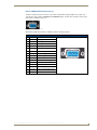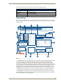
1
Enova DVX-2100HD 6x2 All-in-One Presentation Switcher Operation/Reference Guide Operation/Reference Guide Enova DVX-2100HD 6x2 All-in-One Presentation Switcher DVX-2100HD-SP DVX-2100HD-T All-In-One Presentation Switchers Latest Release: 05/30/2011 AMX Limited Warranty and Disclaimer This Limited Warranty and Disclaimer extends only to products purchased directly from AMX or an AMX Authorized Partner which include AMX Dealers, Distributors, VIP’s or other AMX authorized entity. AMX warrants its products to be free of defects in material and workmanship under normal use for three (3) years from the date of purchase, with the following exceptions: • Electroluminescent and LCD Control Panels are warranted for three (3) years, except for the display and touch overlay components are warranted for a period of one (1) year. • Disk drive mechanisms, pan/tilt heads, power supplies, and MX Series products are warranted for a period of one (1) year. • AMX lighting products are guaranteed to switch on and off any load that is properly connected to our lighting products, as long as the AMX lighting products are under warranty. AMX also guarantees the control of dimmable loads that are properly connected to our lighting products. The dimming performance or quality there of is not guaranteed, impart due to the random combinations of dimmers, lamps and ballasts or transformers. • AMX software is warranted for a period of ninety (90) days. • Batteries and incandescent lamps are not covered under the warranty. • AMX AutoPatch Epica, Modula, Modula Series4, Modula CatPro Series and 8Y-3000 product models will be free of defects in materials and manufacture at the time of sale and will remain in good working order for a period of three (3) years following the date of the original sales invoice from AMX. The three-year warranty period will be extended to the life of the product (Limited Lifetime Warranty) if the warranty card is filled out by the dealer and/or end user and returned to AMX so that AMX receives it within thirty (30) days of the installation of equipment but no later than six (6) months from original AMX sales invoice date. The life of the product extends until five (5) years after AMX ceases manufacturing the product model. The Limited Lifetime Warranty applies to products in their original installation only. If a product is moved to a different installation, the Limited Lifetime Warranty will no longer apply, and the product warranty will instead be the three (3) year Limited Warranty. All products returned to AMX require a Return Material Authorization (RMA) number. The RMA number is obtained from the AMX RMA Department. The RMA number must be clearly marked on the outside of each box. The RMA is valid for a 30-day period. After the 30-day period the RMA will be cancelled. Any shipments received not consistent with the RMA, or after the RMA is cancelled, will be refused. AMX is not responsible for products returned without a valid RMA number. AMX is not liable for any damages caused by its products or for the failure of its products to perform. This includes any lost profits, lost savings, incidental damages, or consequential damages. AMX is not liable for any claim made by a third party or by an AMX Authorized Partner for a third party. This Limited Warranty does not apply to (a) any AMX product that has been modified, altered or repaired by an unauthorized agent or improperly transported, stored, installed, used, or maintained; (b) damage caused by acts of nature, including flood, erosion, or earthquake; (c) damage caused by a sustained low or high voltage situation or by a low or high voltage disturbance, including brownouts, sags, spikes, or power outages; or (d) damage caused by war, vandalism, theft, depletion, or obsolescence. This limitation of liability applies whether damages are sought, or a claim is made, under this warranty or as a tort claim (including negligence and strict product liability), a contract claim, or any other claim. This limitation of liability cannot be waived or amended by any person. This limitation of liability will be effective even if AMX or an authorized representative of AMX has been advised of the possibility of any such damages. This limitation of liability, however, will not apply to claims for personal injury. Some states do not allow a limitation of how long an implied warranty last. Some states do not allow the limitation or exclusion of incidental or consequential damages for consumer products. In such states, the limitation or exclusion of the Limited Warranty may not apply. This Limited Warranty gives the owner specific legal rights. The owner may also have other rights that vary from state to state. The owner is advised to consult applicable state laws for full determination of rights. EXCEPT AS EXPRESSLY SET FORTH IN THIS WARRANTY, AMX MAKES NO OTHER WARRANTIES, EXPRESSED OR IMPLIED, INCLUDING ANY IMPLIED WARRANTIES OF MERCHANTABILITY OR FITNESS FOR A PARTICULAR PURPOSE. AMX EXPRESSLY DISCLAIMS ALL WARRANTIES NOT STATED IN THIS LIMITED WARRANTY. ANY IMPLIED WARRANTIES THAT MAY BE IMPOSED BY LAW ARE LIMITED TO THE TERMS OF THIS LIMITED WARRANTY. EXCEPT AS OTHERWISE LIMITED BY APPLICABLE LAW, AMX RESERVES THE RIGHT TO MODIFY OR DISCONTINUE DESIGNS, SPECIFICATIONS, WARRANTIES, PRICES, AND POLICIES WITHOUT NOTICE. Important Safety Instructions Important Safety Instructions 1. 2. 3. 4. 5. 6. 7. 8. Read the instructions. Keep the instructions. Heed all warnings. Follow the instructions. Do not use this apparatus near water. Clean this apparatus only with a dry cloth. Do not block any ventilation openings. Install in accordance with the manufacturer's instructions. Do not install near any heat sources such as radiators, heat registers, stoves, or other apparatus (including amplifiers) that produce heat. 9. Do not defeat the safety purpose of the grounding type plug. The grounding plug has two blades and a third grounding prong. The third prong is provided for your safety. If the provided plug does not fit into your outlet, consult an electrician for replacement of the obsolete outlet. 10. Protect the power cord from being walked on or pinched particularly at plugs, convenience receptacles, and the point where they exit from the apparatus. 11. Only use attachments/accessories specified by the manufacturer. 12. Use only with the cart, stand, tripod, bracket, or table specified by the manufacturer, or sold with the apparatus. When a cart is used, use caution when mobbing the cart/apparatus combination to avoid injury from tipping-over. 13. Unplug this apparatus during lightning storms or when unused for long periods of time. 14. Refer all servicing to qualified personnel. Servicing is required when the apparatus has been damaged in any way, such as power supply cord or plug is damaged, liquid has been spilled or objects have fallen into the apparatus, the apparatus has been exposed to rain or moisture, does not operate normally, or has been dropped. WARNING: To reduce the risk of fire or electric shock, do not expose this apparatus to rain or moisture. Enova DVX-2100HD 6x2 All-In-One Presentation Switcher Operation/Reference Guide i Important Safety Instructions ii Enova DVX-2100HD 6x2 All-In-One Presentation Switcher Operation/Reference Guide Table of Contents Table of Contents Important Safety Instructions .............................................................................. i Overview ............................................................................................................1 Common Application....................................................................................................... 1 Audio Processing............................................................................................................. 1 Integrated Control .......................................................................................................... 1 AMXmeetingroom........................................................................................................... 1 DVX-2100HD Specifications ..................................................................................... 2 Mounting the DVX-2100HD into an Equipment Rack ............................................... 6 Ventilation....................................................................................................................... 7 Wiring and Device Connections ..........................................................................9 Overview .................................................................................................................. 9 Front Panel Components ........................................................................................ 10 LEDs .............................................................................................................................. 10 MACROS Pushbuttons................................................................................................... 10 INPUT SELECT Pushbuttons .......................................................................................... 11 MIC SELECT Pushbuttons.............................................................................................. 12 LCD Display................................................................................................................... 12 VIDEO MENU Pushbutton............................................................................................. 12 AUDIO MENU Pushbutton ............................................................................................ 13 TOOLS Menu Activation................................................................................................ 13 Navigation Pushbuttons ................................................................................................ 13 VIDEO/AUDIO MUTE Pushbuttons................................................................................ 14 Rear Panel Components.......................................................................................... 14 RS-232/422/485 Serial Port Connectors (PORT 1, PORT 2, PORT 3)............................. 14 RELAYS (PORT 4)........................................................................................................... 15 I/O (PORT 9) .................................................................................................................. 15 IR/SERIAL (PORTS 5-8) .................................................................................................. 16 CONFIG DIP Switch....................................................................................................... 16 PROGRAM Port (Type-B USB) ....................................................................................... 17 Preparing the DVX-2100HD for Serial Communication ................................................. 17 ID Pushbutton ............................................................................................................... 17 LAN (RJ-45) ................................................................................................................... 18 AxLink Port and LED (4-pin captive-wire) ...................................................................... 19 AUDIO INPUTS (1-4)...................................................................................................... 21 MIC INPUTS (1-2) .......................................................................................................... 22 AUDIO OUTPUT: LINE (Line Level audio) ...................................................................... 23 AUDIO OUTPUT: AMP (Amplified audio) ...................................................................... 24 Enova DVX-2100HD 6x2 All-In-One Presentation Switcher Operation/Reference Guide iii Table of Contents VIDEO INPUTS (1-4) ...................................................................................................... 25 UDM INPUTS (5-6) ......................................................................................................... 26 VIDEO OUTPUTS (1-2) and UDM OUTPUT .................................................................... 28 HD-15 VIDEO OUTPUT Connector (2) ........................................................................... 29 UDM OUTPUT ............................................................................................................... 30 Audio & Video Formats/Resolutions/Distance............................................................... 30 Power Connector/Switch/Fuse ...................................................................................... 31 Example Configuration ........................................................................................... 32 Cable Details and Pinout Information ...............................................................33 Overview ................................................................................................................ 33 DVI-D Male to DVI-D Male Single-Link Cable.......................................................... 33 DVI-to-DVI Cable Pinout Information ........................................................................... 34 DVI-A Male to 5-BNC Male Cable ........................................................................... 35 DVI-to-5-BNC Cable Pinout Information ....................................................................... 35 DVI-A Male to Triple RCA Male Cable .................................................................... 36 DVI-to-Triple RCA Cable Pinout Information ................................................................ 36 DVI-A Male to S-Video Male Cable ......................................................................... 38 DVI-to-S-Video Cable Pinout Information ..................................................................... 38 DVI-A Male to HD15 (VGA) Male Adapter .............................................................. 39 DVI-to-VGA Cable Pinout Information ........................................................................... 39 Audio/Video Configuration ..............................................................................41 Using the Front Panel Buttons ................................................................................ 41 Video Settings ............................................................................................................... 41 Changing the Video Output Resolution ........................................................................ 43 Changing the Output Aspect Ratio ............................................................................... 43 Selecting a Test Pattern ................................................................................................ 43 Audio Settings............................................................................................................... 43 Tools Menu.................................................................................................................... 46 DVX-2100HD WebConsole ..................................................................................... 47 Accessing the WebConsole ........................................................................................... 47 Master Controller Configuration Options ............................................................... 48 WebConsole - Master Configuration Manager .............................................................. 48 Master Configuration Manager - Additional Documentation ........................................ 48 Using a Web Browser ............................................................................................. 49 Locating the IP Address of the Presentation Switcher .................................................. 50 Global Settings ....................................................................................................... 50 Video Settings ........................................................................................................ 51 Audio Settings ........................................................................................................ 53 System Settings ...................................................................................................... 56 iv Enova DVX-2100HD 6x2 All-In-One Presentation Switcher Operation/Reference Guide Table of Contents DVX-2100HD Audio Processing Functional Block Diagram .................................... 57 NetLinx Firmware Upgrades .............................................................................61 Overview ................................................................................................................ 61 Before You Start ..................................................................................................... 61 Sending Firmware (*.KIT) Files to the DVX-2100HD ............................................... 61 Additional Documentation ............................................................................................ 64 AMXmeetingroom ............................................................................................65 Communications ..................................................................................................... 65 Load Master/Panel.................................................................................................. 65 License Key/Demo Mode .............................................................................................. 66 Product Summary ................................................................................................... 66 Web Assistant ......................................................................................................... 66 Training................................................................................................................... 66 Programming ....................................................................................................67 NetLinx Commands................................................................................................. 67 NetLinx Channels .......................................................................................................... 67 NetLinx Levels............................................................................................................... 68 NetLinx Protocol ........................................................................................................... 68 SEND_COMMANDS................................................................................................ 69 AUDIO SEND_COMMANDs .......................................................................................... 70 AI<input>O<output> ................................................................................................................ ?AUDIN_NAME ......................................................................................................................... AUDIN_NAME ........................................................................................................................... ?AUDIN_STEREO....................................................................................................................... AUDIN_STEREO ........................................................................................................................ ?AUDIO_MUTE .......................................................................................................................... AUDIO_MUTE............................................................................................................................ ?AUDMIC_GAIN ........................................................................................................................ AUDMIC_GAIN .......................................................................................................................... ?AUDMIC_LIMITER .................................................................................................................... AUDMIC_LIMITER...................................................................................................................... ?AUDMIC_ON ........................................................................................................................... AUDMIC_ON ............................................................................................................................. ?AUDMIC_PREAMP_GAIN......................................................................................................... AUDMIC_PREAMP_GAIN .......................................................................................................... ?AUDMIC_STEREO .................................................................................................................... AUDMIC_STEREO...................................................................................................................... ?AUDOUT_STEREO ................................................................................................................... AUDOUT_STEREO..................................................................................................................... ?AUDOUT_UDM ........................................................................................................................ AUDOUT_UDM.......................................................................................................................... ?AUDOUT_VARIABLE................................................................................................................ AUDOUT_VARIABLE.................................................................................................................. ?EQUALIZER.............................................................................................................................. Enova DVX-2100HD 6x2 All-In-One Presentation Switcher Operation/Reference Guide 70 70 70 70 70 71 71 71 71 71 71 72 72 72 72 72 72 72 73 73 73 73 73 73 v Table of Contents EQUALIZER............................................................................................................................... ?GAIN ....................................................................................................................................... GAIN ......................................................................................................................................... ?INPUTEQ................................................................................................................................. INPUTEQ................................................................................................................................... ?PHANTOM_PWR ..................................................................................................................... PHANTOM_PWR....................................................................................................................... ?VOLUME ................................................................................................................................. VOLUME ................................................................................................................................... ?XPOINT ................................................................................................................................... XPOINT..................................................................................................................................... 74 74 74 74 74 74 75 75 75 75 75 Video SEND_COMMANDs ............................................................................................ 76 CI<input>O<output>................................................................................................................ CL.............................................................................................................................................. ?INPUT...................................................................................................................................... ?OSD......................................................................................................................................... OSD .......................................................................................................................................... ?OUTPUT .................................................................................................................................. ?VIDEO_MUTE .......................................................................................................................... VIDEO_MUTE............................................................................................................................ ?VIDEO_TESTPATTERN ............................................................................................................ VIDEO_TESTPATTERN .............................................................................................................. ?VIDIN_BRIGHTNESS................................................................................................................ VIDIN_BRIGHTNESS.................................................................................................................. ?VIDIN_COLOR ......................................................................................................................... VIDIN_COLOR........................................................................................................................... ?VIDIN_CONTRAST................................................................................................................... VIDIN_CONTRAST .................................................................................................................... ?VIDIN_FORMAT ...................................................................................................................... VIDIN_FORMAT ........................................................................................................................ VIDIN_HSHIFT........................................................................................................................... ?VIDIN_HUE.............................................................................................................................. VIDIN_HUE................................................................................................................................ ?VIDIN_NAME .......................................................................................................................... VIDIN_NAME ............................................................................................................................ ?VIDIN_PHASE.......................................................................................................................... VIDIN_PHASE............................................................................................................................ ?VIDIN_RES_AUTO ................................................................................................................... VIDIN_RES_AUTO ..................................................................................................................... ?VIDIN_RES_REF....................................................................................................................... VIDIN_RES_REF......................................................................................................................... ?VIDIN_SATURATION ............................................................................................................... VIDIN_SATURATION................................................................................................................. ?VIDIN_STATUS ........................................................................................................................ ?VIDOUT_ASPECT_RATIO......................................................................................................... VIDOUT_ASPECT_RATIO .......................................................................................................... ?VIDOUT_RES ........................................................................................................................... ?VIDOUT_RES_AUTO................................................................................................................ VIDOUT_RES_AUTO.................................................................................................................. vi 76 76 77 77 77 77 77 78 78 78 78 78 78 79 79 79 79 79 79 80 80 80 80 80 80 81 81 81 81 81 81 82 82 82 82 82 82 Enova DVX-2100HD 6x2 All-In-One Presentation Switcher Operation/Reference Guide Table of Contents ?VIDOUT_RES_REF.................................................................................................................... 83 VIDOUT_RES_REF ..................................................................................................................... 83 VI<input>O<output> ................................................................................................................ 83 Front Panel SEND_COMMANDs ................................................................................... 84 COLOR ...................................................................................................................................... ?FP_LOCKOUT .......................................................................................................................... FP_LOCKOUT ............................................................................................................................ ?FP_LOCKTYPE ......................................................................................................................... FP_LOCKTYPE ........................................................................................................................... ?INTENSITY_LCD....................................................................................................................... 84 84 84 84 84 84 System SEND_COMMANDs .......................................................................................... 85 ?DSP_FWVERSION .................................................................................................................... ?FGPA_FWVERSION ................................................................................................................. INTENSITY_LCD ........................................................................................................................ ?INTENSITY_LEDS ..................................................................................................................... INTENSITY_LEDS....................................................................................................................... 85 85 85 85 85 UTP Input SEND_COMMANDs...................................................................................... 86 ?SB ............................................................................................................................................ SB .............................................................................................................................................. ?SS ............................................................................................................................................ SS .............................................................................................................................................. ?WPVIDEO ................................................................................................................................ 86 86 86 86 86 UDM-Connected Device NetLinx Commands ......................................................... 87 UDM Channels............................................................................................................... 87 UDM Levels ................................................................................................................... 87 UDM Commands ........................................................................................................... 87 RP .............................................................................................................................................. ?RP ............................................................................................................................................ ?SB ............................................................................................................................................ SB .............................................................................................................................................. SD.............................................................................................................................................. ?SKB .......................................................................................................................................... SKB............................................................................................................................................ ?SKG ......................................................................................................................................... SKG ........................................................................................................................................... ?SKR .......................................................................................................................................... SKR............................................................................................................................................ ?SS ............................................................................................................................................ SS .............................................................................................................................................. 87 87 88 88 88 88 88 88 89 89 89 89 89 IR SEND_COMMANDs .................................................................................................. 90 CAROFF..................................................................................................................................... CARON...................................................................................................................................... CH ............................................................................................................................................. CP.............................................................................................................................................. CTOF ......................................................................................................................................... CTON ........................................................................................................................................ IROFF ........................................................................................................................................ SP .............................................................................................................................................. Enova DVX-2100HD 6x2 All-In-One Presentation Switcher Operation/Reference Guide 90 90 90 90 91 91 91 91 vii Table of Contents XCH .......................................................................................................................................... 91 XCHM ....................................................................................................................................... 92 Serial SEND_COMMANDs............................................................................................. 93 CHARD...................................................................................................................................... CHARDM................................................................................................................................... GET BAUD ................................................................................................................................ RXCLR ....................................................................................................................................... RXOFF ...................................................................................................................................... RXON........................................................................................................................................ SET BAUD ................................................................................................................................. TXCLR ....................................................................................................................................... 93 93 93 93 93 94 94 94 Appendix A ......................................................................................................95 Available Pixel Display and Refresh Rates .............................................................. 95 DVI and VGA Supported Input Resolutions................................................................... 95 Composite and S-Video Supported Input Resolutions................................................... 97 Component Video Supported Input Resolutions ........................................................... 97 DVI and VGA Supported Output Resolutions................................................................ 97 viii Enova DVX-2100HD 6x2 All-In-One Presentation Switcher Operation/Reference Guide Overview Overview The Enova DVX-2100HD-SP (FG1905-01, -04) and DVX-2100HD-T (FG1905-02, -05) All-in-One Presentation Switchers combine all of the components you need to control/automate any environment into a simple, flexible, comprehensive solution including control, multi-format inputs, audio and video switching, transcoding and scaling, local and remote distribution, plus audio mixing, and amplification - all in a single box (FIG. 1). FIG. 1 Enova DVX-2100HD-SP Common Application The DVX-2100HD is an ideal solution when used to simplify A/V control and distribution in sophisticated presentation environments and conference rooms, including those supporting audio and video conferencing. It also fits well in classrooms and auditoriums that need multiple displays, or video previewing. Audio Processing The DVX-2100HD-SP features built-in audio mixing and amplification that outputs two channels at 25 Watts each into 8-ohms after passing through a mixer and an integrated equalizer to accommodate the size, furnishings, surfaces, and functional requirements in every room. There is also a stereo line level output with its own mixing and equalization settings. The DVX-2100HD-T can deliver 70V and 100V amplified variable mono audio. This unit combines the left and right stereo audio signals into a single, Mono audio signal. For convenience, both 70V and 100V outputs are provided on separate connectors, however you should use only one output at a time. Integrated Control The DVX-2100HD includes the equivalent of a NetLinx 2100 central controller. The DVX also includes a front control panel for an added level of convenience. The DVX features standard RS-232, IR, digital I/O, and relay control ports for control over environment and third-party equipment. AMXmeetingroom The DVX-2100HD supports AMXmeetingroom. AMXmeetingroom allows for a more simplified configuration of your system by using a connected touch panel. AMXmeetingroom contains an easy-to-use Configuration Wizard which enables you to supply information about your system and its connections and uses the information provided to create an interface you can use to select devices and change settings. The AMXmeetingroom license is locked to the presentation switcher, and it cannot be copied to another master. Enova DVX-2100HD 6x2 All-in-One Presentation Switcher Operation/Reference Guide 1 Overview DVX-2100HD Specifications DVX-2100HD Specifications Power: 110-240V, 47/63 Hz, 2.5A maximum AC supply Memory: • 64 MB SDRAM • 1 MB Non-volatile (NV) SRAM Flash: 256 MB Amplifier: • 2 x 25W into 8 Ohms Class D stereo amplifier (capable of driving loads in the range of 2-8 ohms) (DVX-2100HD-SP) • 70V or 100V at 75W amplified variable mono audio (DVX-2100HD-T) Integrated Controller: Equivalent of a NetLinx 2100 central controller on-board. Front Panel Components: LEDs: • LINK/ACT (green) - Link/Activity LED blinks when receiving Ethernet data packets. • STATUS (green) - Status LED blinks to indicate that the system is programmed and communicating properly. • INPUT (yellow) - Input LED blinks to indicate that the Controller is receiving data. • OUTPUT (red) - Output LED blinks to indicate that the Controller is transmitting data. • RS-232 / 422 / 485 (red/yellow) - 3 sets of LEDs indicate that RS-232/422/485 Ports (1-3) are transmitting or receiving data. • RELAYS (red) - 4 LEDs indicate that one or more of the relay channels (1-4) are active (closed). • IR/SERIAL (red) - 4 LEDs indicate that one or more of the IR/Serial channels (1-4) are transmitting control data. • I/O (yellow) - 4 LEDs indicate that one or more of the I/O channels (1-4) are active. MACROS pushbuttons: 4 back-lit pushbuttons allow access to macro functions. INPUT SELECT pushbuttons: 6 back-lit (multi-color) source selection pushbuttons select an Input (source). MIC SELECT pushbuttons: 2 back-lit (yellow) buttons for selecting a microphone. LCD display: Liquid crystal display (2 lines with 20 characters per line) indicates current volume level and displays the Video, Audio, and Tools menus. Macro functions are programmed via NetLinx code. See the MACROS Pushbuttons section on page 10 for details. Pressing an INPUT SELECT button after pressing the VIDEO MENU button activates only the video for the source input. Similarly, pressing the AUDIO MENU button followed by an INPUT SELECT button activates only the audio on the source input. Pressing an input select button when not in a menu mode switches both the audio and video. See the INPUT SELECT Pushbuttons section on page 11 for details. Each button lights to indicate that a microphone is selected. See the LCD Display section on page 12 for details. VIDEO MENU pushbutton: Press to access the Video menu on the LCD display. Press both the AUDIO and VIDEO menu buttons to access the Tools menu. AUDIO MENU pushbutton: Press to access the Audio menu on the LCD display. Press both the AUDIO and VIDEO menu buttons to access the Tools menu. Navigational 4 directional buttons for navigating the options in the Video and Audio menu (on the LCD display). pushbuttons: 2 VIDEO MUTE pushbutton: Press to mute/un-mute (enable/disable) all video output displays. AUDIO MUTE pushbutton: Press to mute/un-mute all audio outputs. Video Mute results in a blank screen on the output displays. Enova DVX-2100HD 6x2 All-in-One Presentation Switcher Operation/Reference Guide Overview DVX-2100HD Specifications (Cont.) Rear Panel Components: RS-232/422/485 (PORT 1-3): RS-232/422/485 Ports 1-3 provide serial control via DB9 (male) connectors: • XON/XOFF (transmit on/transmit off) • CTS/RTS (clear to send/ready to send) • 300-115,200 baud RELAYS (PORT 4): Port 4 provides Relay control via 8-pin 3.5 mm captive-wire connector. • 4-channel single-pole single-throw relay ports • Each relay is independently controlled • Supports up to 4 independent external relay devices • Channel range = 1-4 • Each relay can switch up to 24 VDC or 28 VAC @ 1 A • One 8-pin 3.5 mm mini-Phoenix (female) connectors provide relay termination IR/SERIAL (PORTS 5-8): Ports 5-8 provide IR/Serial control via 2-pin 3.5 mm captive-wire connectors. • Supports high-frequency carriers of up to 1.142 MHz. • 4 IR/Serial data signals can be generated simultaneously. I/O (PORT 9): Port 9 provides 4-channel binary I/O port for contact closure with each input being capable of voltage sensing. Input format is software selectable with interactive power sensing for IR ports. AUDIO INPUTS: 4 3.5mm 5-pin captive-wire connectors receive up to four balanced/unbalanced line level audio inputs. • Nominal input level: +4 dBu (1.228 Vrms) balanced or -10 dBV (0.3162 Vrms) unbalanced • Maximum input level: 2 Vrms • Input impedance: >12k ohms unbalanced, >12k ohms balanced, DC coupled MIC INPUTS: 2 3.5mm 3-pin captive-wire connectors receive up to 2 mono microphones (balanced or unbalanced audio and switchable Phantom Power). AUDIO OUTPUTS: • LINE: 1 3.5mm 5-pin captive-wire connector provides for fixed or variable, balanced or unbalanced, mono or stereo line level audio output. • AMP: 4-position captive wire connector provides amplified audio output with volume control (DVX-2100HD-SP only). • AMP: Two 2-position captive wire connector provides 70V or 100V mono amplified audio output (DVX-2100HD-T only). VIDEO INPUTS (1-4): 4 DVI-I input connectors provide multi-format video inputs for up to four video sources. Each VIDEO INPUT connector supports RGBHV, S-video, composite video, component video, and DVI input. See the Available Pixel Display and Refresh Rates section on page 95 for information on supported video formats and resolutions. UDM INPUTS (5-6): 2 RJ-45 inputs receive audio and video from up to two UDM Multi-Format Distribution Hubs or UPX wallplates. The DVX-2100HD is compatible with all UDM Multi-Format Distribution Hubs and UPX wallplates. VIDEO OUTPUTS (1-2): • 2 DVI-I Output connectors each provide simultaneous digital DVI and analog RGBHV video output (FG1905-04 and -05 only). You can view both Digital and Analog signals at the same time by using a DVI-I to DVI-D/HD15 splitter. See the VIDEO OUTPUTS (1-2) and UDM OUTPUT section on page 28 for details. • 1 DVI-I digital and analog Output connector and RGB analog only output connector (FG1905-01 and -02 only). See the Power Connector/Switch/Fuse section on page 31 for details. UDM OUTPUT (1): 1 RJ-45 connector allows the DVX-2100HD to connect to a UDM Multi-Format Receiver. The Video on this output is identical to DVI output 1. You can configure the audio to follow either the AMP or Line outputs. Enova DVX-2100HD 6x2 All-in-One Presentation Switcher Operation/Reference Guide 3 Overview DVX-2100HD Specifications (Cont.) Rear Panel Components (Cont.): CONFIG DIP Switch: 4-position Master configuration DIP switch allows setting the onboard Master execution mode (PRD or normal). See the CONFIG DIP Switch section on page 16 for details. PROGRAM Port: Type-B USB connector connects the DVX-2100HD to a USB port on a PC. This USB connection is used to configure system settings. Note: Not recommended for firmware updates or large file transfers. These more data-intensive operations are better handled via Ethernet. See the PROGRAM Port (Type-B USB) section on page 17 for details. ID Pushbutton: Black ID pushbutton sets the NetLinx Device ID assignments of the Internal Control Device. It has no effect on the Internal Switcher Device. See the ID Pushbutton section on page 17 for details. ETHERNET 10/100 Port: RJ-45 connector provides TCP/IP communication. This is an Auto MDI/MDI-X enabled port, which allows you to use either straight-through or crossover Ethernet cables. The Ethernet Port LEDs show communication activity, connection status, speeds, and mode information: • SPD (speed) - Yellow LED lights On when the connection speed is 100 Mbps and turns Off when the speed is 10 Mbps. • L/A (link/activity) - Green LED lights On when the Ethernet cables are connected and terminated correctly, and blinks when receiving Ethernet data packets. See the LAN (RJ-45) section on page 18 for details. AxLink Port: 1 3.5 mm captive-wire connector provides data and power to external control devices. The AxLink LED (green) indicates the state of the AxLink port. The AxLink port can be used to supply power to downstream AxLink-compatible devices as long as the maximum current draw is less than 2A. Note: The AxLink port provides only limited power to connected AxLink devices. It is recommended to use an alternate power source when connecting AxLink devices to the DVX-2100HD. See the AxLink Port and LED (4-pin captive-wire) section on page 19 for details. Power Connector: IEC Power cord connector: • 100-240V AC • 47-63Hz • 2.5A maximum Operating Environment: • Storage temperature: -10º C to 60º C (14º F to 140º F) • Operating Temperature: 0º C to 40º C (32º F to 104º F) • Operating Relative Humidity: 5% to 85% non-condensing Supported Video Resolutions: HD resolutions up to 1080p and RGB resolutions up to 1920 x 1200 @ 60Hz Dimensions (HWD): • 3.5" x 17" x 14.25" • 8.89cm x 43.18cm x 36.2cm Weight: • 14.7 lbs (6.67 kg) Enclosure: Metal with black matte finish Certifications: • RoHS • FCC Class B • CE • CB Scheme • UL 4 Enova DVX-2100HD 6x2 All-in-One Presentation Switcher Operation/Reference Guide Overview DVX-2100HD Specifications (Cont.) Included Accessories: • 2 CC-NIRC, IR Emitter w/3.5mm Phoenix (FG10-000-11) • 2 CC-DVIM-VGAF, DVI to VGA Adapter (FG10-2170-13) • 2 Front Rack Mounting Brackets (62-1905-04) • Enova DVX-2100HD All-in-One Presentation Switcher Installation Guide (93-1950-01) Optional Accessories: • CC-DVI-5BNCM DVI to 5 BNC adapter cable (FG10-2170-08) • CC-DVI-RCA3M DVI to 3 Male RCA adapter cable for component and composite connections (FG10-2170-09) • CC-DVI-SVID DVI to S-Video adapter cable (FG10-2170-10) • CC-3.5ST5-RCA2F 2 RCA Female to 5-Pin Phoenix Cable (FG10-003-20) • UDM-RX02N Multi-Format Receiver with Native NetLinx Control (FG1402-20) • UPX-CS+A-US Composite Universal Transmitter Wallplate (US) (FG1402-50-SW/SB/SA) • UPX-CS+A-UK Composite Universal Transmitter Wallplate (UK) (FG1402-50-KW/KB/KA) • UPX-CS+A-EU Composite Universal Transmitter Wallplate (EU) (FG1402-50-EW/EB/EA) • UPX-RGB+A-US RGB Universal Transmitter Wallplate (US) (FG1402-51-SW/SB/SA) • UPX-RGB+A-UK RGB Universal Transmitter Wallplate (UK) (FG1402-51-KW/KB/KA) • UPX-RGB+A-EU RGB Universal Transmitter Wallplate (EU) (FG1402-51-EW/EB/EA) • UPX-CN+A-US Component Universal Transmitter Wallplate (US) (FG1402-52-SW/SB/SA) • UPX-CN+A-UK Component Universal Transmitter Wallplate (UK) (FG1402-52-KW/KB/KA) • UPX-CN+A-EU Component Universal Transmitter Wallplate (EU) (FG1402-52-EW/EB/EA) • UPX-CS+A-DE-B/W Composite Universal Transmitter Wallplate (Decor Style) (FG1402-50-DW) • UPX-RGB+A-DE-B/W RGB Universal Transmitter Wallplate (Decor Style) (FG1402-51-DW) • UPX-CN+A-DE-B/W Component Universal Transmitter Wallplate (Decor Style) (FG1402-52-DW) • UPX-HDMI+A-US-W/B/AL HDMI Pass-through Universal Transmitter Wallplate (US) (FG1402-53-SW/SB/SA) • UPX-HDMI+A-DE-W/B HDMI Pass-through Universal Transmitter Wallplate (Decor Style) (FG1402-53-DW/DB) Enova DVX-2100HD 6x2 All-in-One Presentation Switcher Operation/Reference Guide 5 Overview Mounting the DVX-2100HD into an Equipment Rack The DVX-2100HD occupies two rack units in a standard equipment rack. The following steps apply to mounting the DVX-2100HD. 1. Discharge any static electricity from your body by touching a grounded metal object. 2. Position and install the mounting brackets, as shown in FIG. 2, using the supplied mounting screws. Mounting screws Mounting holes Mounting bracket front Mounting screws Mounting bracket FIG. 2 Rack mounting the DVX-2100HD 3. Install the DVX-2100HD in the mounting rack by using the mounting screws to affix the unit to the rack. 4. Connect any applicable wires to the DVX-2100HD. Refer to the Wiring and Device Connections section on page 9 for wiring diagrams and pinout descriptions. Connect the unit only to a properly-rated supply circuit. DO NOT stand other units directly on top of the DVX-2100HD when it is rack mounted, as this will place excessive strain on the mounting brackets. 6 Enova DVX-2100HD 6x2 All-in-One Presentation Switcher Operation/Reference Guide Overview Ventilation ALWAYS ensure that the rack enclosure is adequately ventilated. The maximum operating ambient temperature is 40°C (104°F). Sufficient airflow must be achieved (by convection or forced-air cooling) to satisfy the ventilation requirements of all the items of equipment installed within the rack. When installing equipment into a rack, distribute the units evenly. Otherwise, hazardous conditions may be created by an uneven weight distribution. Reliable earthing (grounding) of rack-mounted equipment should be maintained. It is recommended that you leave 1 RU of space above the DVX-2100HD when you install it in a rack. Enova DVX-2100HD 6x2 All-in-One Presentation Switcher Operation/Reference Guide 7 Overview 8 Enova DVX-2100HD 6x2 All-in-One Presentation Switcher Operation/Reference Guide Wiring and Device Connections Wiring and Device Connections Overview FIG. 3 displays the front panel of the DVX-2100HD-SP: LCD Display Output LED Input LED Status LED LINK/ACT LED MACROS Pushbuttons Serial Port LEDs INPUT SELECT Pushbuttons Relay LEDs MIC SELECT Pushbuttons Menu Navigation Buttons I/O LEDs IR/Serial LEDs VIDEO MENU AUDIO MENU VIDEO MUTE AUDIO MUTE FIG. 3 DVX-2100HD-SP front panel FIG. 4 displays the rear panel of the DVX-2100HD-SP with 2 DVI-I outputs and 2x25W Amp (FG1905-04). RS232/422/485 (Ports 1-3) AUDIO INPUTS (1-4) RELAYS (Port 4) MIC INPUTS (1-2) I/O Port (Port 9) UDM INPUTS (5-6) ID Pushbutton PROGRAM (USB) Port CONFIG DIP Switch IR/SERIAL (Ports 5-8) AUDIO OUTPUTS VIDEO INPUTS (DVI-I, 1-4) VIDEO OUTPUTS (DVI-I) LAN Port/LEDs AxLink Port/LED UDM OUTPUT Power connector/Switch FIG. 4 DVX-2100HD-SP rear panel (FG1905-04) The dual DVI-I outputs are only available on FG1905-04 and -05. FIG. 5 displays the rear panel of the DVX-2100HD-SP with 1 RGB Output / 1 DVI-I Output and 2x25W Amp (FG1905-01). The RGB output is only available on FG1905-01 and -02 models. RGB Output DVI-I Output FIG. 5 DVX-2100SP rear panel (FG1905-01) Enova DVX-2100HD 6x2 All-in-One Presentation Switcher Operation/Reference Guide 9 Wiring and Device Connections Front Panel Components The following sub-sections describe each component on the front panel of the DVX-2100HD. Refer to FIG. 3 on page 9 for the component layout of the front panel. LEDs The LEDs on the front panel (FIG. 6) indicate the communications status of several different connections, as described in the table below: LINK/ACT LED Status LED Output LED Input LED RS-232/422/485 LEDs Relay LEDs IR/Serial I/O LEDs LEDs FIG. 6 Front Panel -LEDs Front Panel LEDs Label Color Description LINK/ACT green Blinks when receiving LAN data packets. STATUS green Blinks to indicate that the system is programmed and communicating properly. INPUT yellow Blinks to indicate that the Controller is receiving data. OUTPUT red Blinks to indicate that the Controller is transmitting data. RS-232/422/485 (1-3) red/yellow 3 sets of LEDs indicate that RS-232/422/485 Ports (1-3) are transmitting or receiving data. • Yellow = receiving data • Red = transmitting data RELAYS (1-4) red Lights to indicate that one or more of the relay channels (1-4) are currently active (closed). IR/SERIAL (1-4) red Lights to indicate that one or more of the IR/Serial channels (1-4) are currently transmitting control data. I/O (1-4) yellow Lights to indicate that one or more of the I/O channels (1-4) are currently active. MACROS Pushbuttons The four backlit MACROS pushbuttons (FIG. 7) allow you to select macro functions. Push to initiate Macro #1 Push to initiate Macro #2 Push to initiate Macro #3 Push to initiate Macro #4 FIG. 7 MACROS pushbuttons Macro functions are defined in NetLinx code. The on/off states and backlight color of the MACRO buttons are under control of the NetLinx program. You can define macros as any typical button event in NetLinx code, and assign the event to any of the four buttons on the DVX. Refer to the NetLinx Studio Operation/Reference Guide and the NetLinx Programming Language Reference Guide for information on programming macros. 10 Enova DVX-2100HD 6x2 All-in-One Presentation Switcher Operation/Reference Guide Wiring and Device Connections INPUT SELECT Pushbuttons The six backlit INPUT SELECT buttons (1-6) allow you to switch Video-only, Audio-only or Video+Audio (FIG. 8). Push to select Input #1 Push to select Input #2 Push to select Input #3 Push to select Input #4 Push to select Input #5 Push to select Input #6 = Video only (blue) = Audio only (yellow) = Audio+Video (green) = Audio+Video, but video signal cannot be displayed (magenta) = Video, but input signal cannot be displayed (red) FIG. 8 INPUT SELECT pushbuttons Each numbered INPUT SELECT button is associated with the corresponding numbered Input on the rear panel (refer to FIG. 4 on page 9): Input Select Options INPUT SELECT Button Corresponding Input Connector Input 1 VIDEO INPUT 1 (DVI-I connector) Input 2 VIDEO INPUT 2 (DVI-I connector) Input 3 VIDEO INPUT 3 (DVI-I connector) Input 4 VIDEO INPUT 4 (DVI-I connector) Input 5 UDM INPUT 5 (RJ45 connector) Input 6 UDM INPUT 6 (RJ45 connector) These pushbuttons use multi color LEDs to indicate various states of input selection: When you press an inactive input select button when not in a menu, the button lights green and activates the audio and video for the source input. Pressing an INPUT SELECT button after pressing the VIDEO MENU button activates only the video for the source input. Similarly, pressing the AUDIO MENU button followed by an INPUT SELECT button activates only the audio on the source input. After making your selection, the selected input type (Audio, Video, or both) is switched to the selected output (see the Video Settings section on page 41 for details on selecting a video output), and the LED displays solid with the corresponding color: Blue = Video only Yellow = Audio only Green = Audio/Video Magenta = Audio/Video, but video signal cannot be displayed Red = Video only, but input signal cannot be displayed Enova DVX-2100HD 6x2 All-in-One Presentation Switcher Operation/Reference Guide 11 Wiring and Device Connections MIC SELECT Pushbuttons The two MIC SELECT (microphone select) pushbuttons (FIG. 9) allow you to toggle the associated microphone input (1 & 2) on and off. Push to select microphone connected to MIC INPUT #1 Push to select microphone connected to MIC INPUT #2 FIG. 9 Microphone Select buttons The MIC SELECT button turns yellow to indicate that the selected microphone is active. When a microphone input is on, the audio from that microphone is mixed with the selected audio source. See the Audio Settings section on page 43 for information on setting mix values and adjusting the microphone levels from the front panel. See the Audio Settings section on page 53 for information on setting mix values and adjusting the microphone levels from the Web interface. LCD Display During normal operation, the 2 x 20 line LCD display (FIG. 10) indicates output volume information. FIG. 10 LCD display The LCD Display also displays VIDEO MENU, AUDIO MENU, and TOOLS MENU selections (see below), and indicates current status of any adjustments made to settings within these menus. VIDEO MENU Pushbutton Press the VIDEO MENU pushbutton (FIG. 11) to access the video options, displayed on the LCD display. Press to access the Video Menu (on the LCD display) FIG. 11 Video Menu button The Video menu enables you to set various options for the incoming video signal and its display output. Use the UP and DOWN navigational buttons to traverse the various options. Use the LEFT and RIGHT navigational buttons to adjust the selected video level or value. Use the Input Select buttons to select the video input to adjust. Adjustments take effect immediately and are saved when you advance to another option or exit the menu. The menu exits automatically after no user interaction on the front panel for 20 seconds. See the Video Settings section on page 41 for a listing of all available options and instructions on how to change the settings. 12 Enova DVX-2100HD 6x2 All-in-One Presentation Switcher Operation/Reference Guide Wiring and Device Connections AUDIO MENU Pushbutton Press the AUDIO MENU pushbutton (FIG. 12) to access the audio options, displayed on the LCD display. Press to access the Audio Menu (on the LCD display) FIG. 12 Audio Menu button The Audio menu enables you to set volume equalization settings for audio inputs and microphones. Use the UP and DOWN navigational buttons to traverse the various options. Use the LEFT and RIGHT navigational buttons to adjust the selected audio level or value. Use the Input Select buttons to choose the audio input to adjust. Adjustments take effect immediately and are saved when you advance to another option or exit the menu. The menu exits automatically after no user interaction on the front panel for 20 seconds. See the Audio Settings section on page 43 for a listing of all available options and instructions on how to change the settings. TOOLS Menu Activation Press both the VIDEO MENU pushbutton and the AUDIO MENU pushbuttons (FIG. 11 and FIG. 12) simultaneously to access the Tools options, displayed on the LCD display. The Tools Menu enables you to see status information such as IP address and installed firmware versions as well as adjust LCD and LED backlight intensity. Use the UP and DOWN navigational buttons to traverse the various options. Use the LEFT and RIGHT navigational buttons to adjust the selected audio level or value. Use the Input Select buttons to choose the audio input to adjust. Adjustments take effect immediately and are saved when you advance to another option or exit the menu. The menu exits automatically after no user interaction on the front panel for 20 seconds. See the Tools Menu section on page 46 for a listing of all available options and instructions on how to change the settings. Navigation Pushbuttons The four directional navigation buttons (Left/Right/Up/Down) enable you to navigate through the menus on the LCD display. Move up to previous menu option Decrease value, or change the state of the selected option Increase value, or change the state of the selected option Move down to next menu option FIG. 13 Navigation buttons The menu selection immediately defaults to selecting an input on the first screen. Enova DVX-2100HD 6x2 All-in-One Presentation Switcher Operation/Reference Guide 13 Wiring and Device Connections VIDEO/AUDIO MUTE Pushbuttons Press the VIDEO MUTE button to enable or disable video on all output displays. Press the AUDIO MUTE button to enable or disable audio for all audio outputs. Press to toggle mute (blank) video all display outputs Press to toggle mute audio on all audio outputs FIG. 14 Audio/Video Mute buttons The pushbuttons light (red) to indicate that Video and/or Audio muting is active. Rear Panel Components The following sub-sections describe each component on the rear panel of the DVX-2100HD. Refer to FIG. 4 on page 9 for the component layout of the rear panel. RS-232/422/485 Serial Port Connectors (PORT 1, PORT 2, PORT 3) The RS-232/422/485 serial device ports (FIG. 15) are used for A/V sources and displays. These ports support most standard RS-232 communication protocols for data transmission. FIG. 15 RS-232/422/485 Device Port connectors FIG. 16 provides wiring specifications for the RS-232/422/485 connectors. 1 2 3 4 5 DB9 Serial Port pinouts (male connector) RS-485 RS-422 RS-232 Pin 2: RX signal Pin 1: RX Pin 1: A (strap to 9) Pin 4: B (strap to 6) Pin 3: TX signal Pin 4: TX + Pin 5: GND Pin 5: GND Pin 5: GND Pin 6: B (strap to 4) Pin 6: RX + Pin 7: RTS Pin 9: A (strap to 1) Pin 8: CTS Pin 9: TX - 6 7 8 9 FIG. 16 RS-232/422/485 (DB9 - male) connector pinouts RS-232/422/485 Port Wiring Specifications Pin 14 Signal Function RS-232 1 RX- Receive data 2 RXD Receive data X 3 TXD Transmit data X 4 TX+ Transmit data 5 GND Signal ground 6 RX+ Receive data 7 RTS Request to send X 8 CTS Clear to send X 9 TX- Transmit data X RS-422 RS-485 X X (strap to pin 9) X X (strap to pin 6) X X X X (strap to pin 4) X X (strap to pin 1) Enova DVX-2100HD 6x2 All-in-One Presentation Switcher Operation/Reference Guide Wiring and Device Connections When wiring the 422/485 connections, do not use pre-made 9-wire cable or connect the wire in the cable to any connection that will not be used by the DB9 serial port. Only use wiring that connects the needed pins. RELAYS (PORT 4) You can connect up to four independent external relay devices to the Relay connectors on the device. Connectors labeled A are for Common and B are for Output (FIG. 17). FIG. 17 RELAYS connectors Each relay is isolated and normally open. I/O (PORT 9) The I/O port (FIG. 18) responds to switch closures and voltage level (high/low) changes, or can be used for logic-level outputs. FIG. 18 I/O connectors A contact closure between the GND and an I/O port is detected as a Push. When used for voltage inputs, the I/O port detects a low signal (0 - 1.5 VDC) as a Push, and a high signal (3.5 - 5 VDC) as a Release (this I/O port uses 5V logic but can handle up to 12V without harm). When used for outputs, the I/O port acts as a switch to GND and is rated for 200mA @ 12 VDC. The PWR pin provides +12 VDC @ 200 mA and is designed as a power output for the PCS Power Current Sensors, VSS2 Video Sync Sensors (or equivalent). The GND connector is a common ground and is shared by all I/O ports. A common ground is shared with I/O ports 1 - 3. The following table provides wiring requirements for the I/O port: I/O Port Wiring Specifications Signal Function +12 VDC: PWR 4: Input/Output 3: Input/Output 2: Input/Output 1: Input/Output GND: Signal GND Enova DVX-2100HD 6x2 All-in-One Presentation Switcher Operation/Reference Guide 15 Wiring and Device Connections IR/SERIAL (PORTS 5-8) You can connect up to four IR- or Serial-controllable devices to the IR/SERIAL connectors (FIG. 19). FIG. 19 IR/SERIAL connectors The IR/SERIAL connectors accept an IR Emitter (CC-NIRC) that mounts onto the device's IR window, or a mini-plug (CC-NSER) that connects to the device's control jack. You can also connect a data (0 - 5 VDC) device. The IR/Serial connector wiring specifications are listed in the following table. IR/Serial Connector Wiring Specifications (per Port) IR connections Port # Signal 1 5 Function GND (-) Signal GND Signal 1 (+) IR/Serial data 2 6 GND (-) Signal GND Signal 2 (+) IR/Serial data 3 7 GND (-) Signal GND Signal 3 (+) IR/Serial data GND (-) Signal GND Signal 4 (+) IR/Serial data 4 8 1 2 3 4 5 6 7 8 1 2 3 4 5 6 7 8 CONFIG DIP Switch Use the Configuration DIP switch (FIG. 20) to set the on-board Master to Program Run Disable (PRD) mode. Position 1 UP (ON) = PRD mode enabled Position 1 DOWN (OFF) = Normal (default) mode - PRD mode disabled Switch position 1 sets PRD mode (UP = ON) FIG. 20 CONFIG DIP switch PRD mode prevents the NetLinx program stored in the on-board Master from running during the device’s power-up. This mode should only be used if the resident NetLinx program is causing inadvertent communication and/or control problems. If necessary, place the on-board Master in PRD mode and use the NetLinx Studio v 2.x program to resolve the communication and/or control problems with the resident NetLinx program. After doing so, download the corrected program, reset the configuration DIP switch to normal mode, recycle power, and try again. To set the CONFIG DIP Switch: 1. Turn off the power switch on the rear of the unit. 2. Set the CONFIG DIP switch (refer to FIG. 20). 3. Turn on the power switch. 16 Enova DVX-2100HD 6x2 All-in-One Presentation Switcher Operation/Reference Guide Wiring and Device Connections Think of the PRD Mode (On) equating to a PC’s SAFE Mode setting. This mode allows a user to continue powering a unit, update the firmware, and download a new program while circumventing any problems with a currently downloaded program. Power must be cycled to the unit after activating/deactivating this mode on the Configuration Port DIP switch #1. PROGRAM Port (Type-B USB) The PROGRAM port is a Type-B USB connector that connects the DVX-2100HD to a USB port on a PC, and is intended primarily to be used to configure system settings (FIG. 21). FIG. 21 PROGRAM port Be sure that your PC's COM port and terminal program's communication settings match those in the table below: PC COM Port Communication Settings Baud 115200 Parity None Data Bits 8 Stop Bits 1 Flow Control None The PROGRAM Port is not recommended for firmware updates or large file transfers. These more data-intensive operations are better handled via LAN. Preparing the DVX-2100HD for Serial Communication 1. Before using the USB port on the DVX-2100HD you must install the appropriate FTDI driver. A link to this driver can be found on the Product web page at www.amx.com. 2. Connect your PC's USB port to the USB Configuration Port on the DVX-21010HD. Either allow Windows to install the driver automatically (internet connection required), or point the installer to the location where you have previously saved the driver. This will create a new virtual COM port on your PC. 3. Edit the Serial Communication settings in NetLinx Studio to use the virtual COM port created in step 2, and set the communication parameters to 115.2K baud, N, 8, 1. ID Pushbutton The ID pushbutton (FIG. 22) sets the NetLinx ID assignments of the Internal Control Device. It has no effect on the Internal Switcher Device. FIG. 22 ID Pushbutton Enova DVX-2100HD 6x2 All-in-One Presentation Switcher Operation/Reference Guide 17 Wiring and Device Connections LAN (RJ-45) The LAN RJ-45 port provides 10/100 Mbps communication via Cat5/5e/6 network cable. FIG. 23 LAN port The LAN port automatically negotiates the connection speed (10 Mbps or 100 Mbps), and whether to use half duplex or full duplex mode. This communication is reflected via the front ICSP LED. FIG. 24 provides the pinouts and signals for the LAN connector and cable. FIG. 24 RJ-45 wiring diagram FIG. 25 describes the blink activity for the LAN connector and cable. L/A - Activity LED (yellow) lights when receiving or transmitting LAN data packets FIG. 25 LAN connector / LEDs 18 A L SPD - Link LED (green) lights when the LAN cables are connected and terminated correctly. ETHERNET Enova DVX-2100HD 6x2 All-in-One Presentation Switcher Operation/Reference Guide Wiring and Device Connections AxLink Port and LED (4-pin captive-wire) The AxLink port (FIG. 26) allows the DVX-2100HD to support AMX AxLink devices. FIG. 26 AxLink Port and LED The (green) AxLink LED indicates AxLink data activity: Off - No power, or the controller is not functioning properly. 1 blink per second - Normal operation. 3 blinks per second - AxLink bus error. Check all AxLink bus connections. The AxLink port can be used to supply power to downstream AxLink-compatible devices as long as the maximum current draw is less than 2 Amps. To isolate the DVX-2100HD from high inrush current, AxLink devices, or potential power faults on the AxLink bus, it is strongly recommended that you power external AxLink devices from an independent power supply. Refer to the following table for the wiring length information used with the DVX-2100HD: Wiring Guidelines Wire size Maximum wiring length 18 AWG 154.83 feet (47.19 meters) 20 AWG 98.30 feet (29.96 meters) 22 AWG 63.40 feet (19.32 meters) 24 AWG 38.68 feet (11.79 meters) FIG. 27 provide wiring requirements for the AxLink connector: To the Controller’s AxLink/PWR connector Top view To the external AxLink device Top view FIG. 27 Mini-Phoenix connector wiring diagram (direct data and power) Enova DVX-2100HD 6x2 All-in-One Presentation Switcher Operation/Reference Guide 19 Wiring and Device Connections To use the 4-pin 3.5 mm mini-Phoenix (female) captive-wire connector for data communication and power transfer, the incoming PWR and GND cable from the 12 VDC-compliant power supply must be connected to the AxLink cable connector going to the presentation switcher. FIG. 28 shows the wiring diagram. Always use a local power supply to power the presentation switcher. To the external AxLink device Top view Local 12+ VDC power supply (coming from an external power supply) To the Controller’s AxLink/PWR connector Top view FIG. 28 4-pin mini-Phoenix connector wiring diagram (using external power source) When you connect an external power supply, do not connect the wire from the PWR terminal (coming from the external device) to the PWR terminal on the Phoenix connector attached to the Controller unit. Make sure to connect only the AXM, AXP, and GND wires to the Controller’s Phoenix connector when using an external power supply. Make sure to connect only the GND wire on the AxLink/PWR connector when using a separate 12 VDC power supply. Do not connect the PWR wire to the AxLink connector’s PWR (+) opening. 20 Enova DVX-2100HD 6x2 All-in-One Presentation Switcher Operation/Reference Guide Wiring and Device Connections AUDIO INPUTS (1-4) The four AUDIO INPUTS connectors are 3.5 mm 5-position captive-wire terminals that can be wired for either balanced (differential) or unbalanced (single-ended) stereo audio (FIG. 29). The four AUDIO INPUT connectors (1-4) do not correspond to the four DVI-I VIDEO INPUT connectors (1-4), however, the DVX-2100HD allows independent switching of video and audio so video and audio inputs of the same number do not have to be connected to the same source equipment. FIG. 29 AUDIO INPUTS connectors Source devices require either balanced (differential) or unbalanced (single-ended) connections. FIG. 30 illustrates options for wiring between sources and input connectors and between output connectors and the destinations. More than one option can be used in the same system. DVX-2100HD source device Balanced wiring Unbalanced wiring FIG. 30 Stereo 5-terminal wiring Enova DVX-2100HD 6x2 All-in-One Presentation Switcher Operation/Reference Guide 21 Wiring and Device Connections FIG. 31 provides details for wiring from an audio input to a non-5 terminal audio source or destination, such as an RCA connector. Positive and ground wires connect to the source or destination connector. You also can use a CC-3.5ST5-RCA2F 2 RCA Female to 5-Pin Phoenix Cable (FG10-003-20) for this type of connection. Do not connect the negative terminals to the source connector. Doing so can cause damage to your device. DVX-2100HD source device FIG. 31 RCA Stereo audio source wiring MIC INPUTS (1-2) Two 3.5mm 3-pin captive-wire MIC INPUT connectors (FIG. 32) allow up to two mono microphones to be connected to the DVX-2100HD. FIG. 32 MIC INPUTS 22 Enova DVX-2100HD 6x2 All-in-One Presentation Switcher Operation/Reference Guide Wiring and Device Connections FIG. 33 illustrates wiring connections between the DVX-2100HD and a mono RCA output and an XLR output. DVX-2100HD DVX-2100HD RCA output XLR output FIG. 33 RCA (mono) and XLR output wiring AUDIO OUTPUT: LINE (Line Level audio) The Line Level audio output provides fixed or variable, balanced or unbalanced, mono or stereo output. FIG. 34 Line Level Audio output Destination devices require either balanced (differential) or unbalanced (single-ended) connections. FIG. 35 illustrates options for wiring between output connectors and the destinations. destination device DVX-2100HD Balanced wiring Unbalanced wiring FIG. 35 Stereo 5-terminal wiring Enova DVX-2100HD 6x2 All-in-One Presentation Switcher Operation/Reference Guide 23 Wiring and Device Connections AUDIO OUTPUT: AMP (Amplified audio) The AMP (amplified) audio output (FIG. 36) provides amplified, variable, mono or stereo audio output. DVX-2100HD-SP DVX-2100HD-T FIG. 36 Amplified Audio Output On the DVX-2100HD-SP, connect speakers to the AMP output as displayed in FIG. 37. FIG. 37 Connecting speakers to the Amplified Audio output (DVX-2100HD-SP) On the DVX-2100HD-T, connect a speaker to either the 70V or 100V terminals as displayed in FIG. 38. ... ... FIG. 38 Connecting speakers to the Amplified Audio output (DVX-2100HD-T) Connect a speaker to either the 70V or 100V terminals, but not both simultaneously. 24 Enova DVX-2100HD 6x2 All-in-One Presentation Switcher Operation/Reference Guide Wiring and Device Connections VIDEO INPUTS (1-4) The four DVI-I VIDEO INPUT connectors on the rear panel are used to connect source input devices to the DVX-2100HD (FIG. 39). The DVX-2100HD routes video from connected source input devices to the connected output devices. The four DVI-I VIDEO INPUT connectors correspond to source select button 1-4 on the front panel. FIG. 39 VIDEO INPUT (DVI-I connectors) These numbered inputs correspond to the numbered INPUT SELECT pushbuttons on the front panel. The DVI Input connectors on the DVX-2100HD are DVI-I (integrated digital/analog) connectors. These connectors support both DVI-A (analog) and DVI-D (digital) inputs. The following table describes the pinout configuration of the DVI-I VIDEO INPUT connectors: DVI-I Input Ports - Pinouts and Signals Pin Signal Pin Signal Pin Signal 1 TMDS Data2- 9 TMDS Data1- 17 TMDS Data0- 2 TMDS Data2+ 10 TMDS Data1+ 18 TMDSData0+ 3 TMDS Data2/4 Shield 11 TMDS Data1/3 Shield 19 TMDS Data0/5 Shield 4 n/c 12 n/c 20 n/c 5 n/c 13 n/c 21 n/c 6 DDC Clock [SCL] 14 +5 V Power 22 TMDS Clock Shield 7 DDC Data [SDA] 15 Ground (for +5 V) 23 TMDS Clock + 8 Analog vertical sync 16 Hot Plug Detect 24 TMDS Clock - C1 Analog Red C2 Analog Green C3 Analog Blue C4 Analog Horizontal Sync C5 Analog Ground If a DVI source is attached before setting the input to DVI, you may need to reboot the source for it to recognize the DVI input description information required by the DVI standard. Each VIDEO INPUT connector supports DVI-D, as well as RGBHV, S-video, Composite, and Component inputs, using the appropriate conversion cables. Refer to the Cable Details and Pinout Information section on page 33 for cable details and pinout information for each cable type: DVI-D Male to DVI-D Male Single-Link Cable section on page 33 DVI-A Male to 5-BNC Male Cable section on page 35 DVI-A Male to Triple RCA Male Cable section on page 36 DVI-A Male to S-Video Male Cable section on page 38 DVI-A Male to HD15 (VGA) Male Adapter section on page 39 Enova DVX-2100HD 6x2 All-in-One Presentation Switcher Operation/Reference Guide 25 Wiring and Device Connections The DVX-2100HD and the adapter cables listed above utilize industry-standard pinouts. The only adapter cable that is unique to AMX is the CC-DVI-SVID (DVI-to-S-Video) cable. The others are generally available to purchase from other vendors, assuming that they also utilize industry standard (or equivalent) pinouts. The following table displays the supported video settings for each type of connection: Supported Video Settings Type Phase Shift S-Video X X Composite X X Hue Saturation Contrast Brightness Component X X RGB X X DVI X X X X X UDM INPUTS (5-6) The UDM INPUT ports 5-6 (FIG. 40) connect to the output ports of UDM Multi-Format Distribution Hubs or UPX Universal Transmitter Wallplates. FIG. 40 UDM INPUTS connectors The DVX-2100HD is compatible with all UDM Multi-Format Distribution Hubs and UPX Universal Transmitter Wallplates. Each input is capable of providing power to a UPX Universal Transmitter Wallplate. Plugging a UDM hub into one of the UDM inputs automatically disables power output on the UDM inputs. Product Documentation for UDM Multi-Format Distribution Hubs is available to view or download from www.amx.com. These are RJ-45 connectors, and the DVX-2100HD can be connected to the UDM Hub or UPX wallplate via CAT5 or CAT5e cabling (FIG. 41). No skew compensation is necessary on UDM inputs as the inputs are designed to be used with 50 meters or less of cable. Levels 8 and 9 control the brightness (gain) and sharpness (compensation) of the UDM input hardware. FIG. 41 RJ-45 Pinouts 26 Enova DVX-2100HD 6x2 All-in-One Presentation Switcher Operation/Reference Guide Wiring and Device Connections The following table lists the pinouts for the UDM ports: UDM Port Pinouts 568A Termination RJ45 Pin # Color 568B Termination A/V Signals Pair # RGB YPbPr CVBS S-Video 1 3 Red + Y+ CVBS S1 + Y+ Color Pair # 2 2 3 Red - Y- CVBS S1 - Y- 2 3 2 Blue + Pr + CVBS S3 + C+ 3 4 1 Green + Pb + CVBS S2 + 5 1 Green - Pb - CVBS S2 - 6 2 Blue - Pr - CVBS S3 - C- 7 4 Audio, Data, Power + Audio, Data, Power + Audio, Data, Power + Audio, Data, Power + 4 8 4 Audio, Data, Power - Audio, Data, Power - Audio, Data, Power - Audio, Data, Power - 4 1 1 3 An incorrectly terminated cable will result in the following scenarios: Incorrectly Terminated Cable Results Pair Composite Video SVideo Component Video RGBHV Video User Port LINK LED 2 No Video 1 No Luma No Y No RED LIT 3 No Video 3 No Chroma No Pr No BLUE LIT 1 No Video 2 NONE No Pb NONE No GREEN NONE LIT NONE 4 The recommended maximum distance for cable runs on the UDM INPUT ports is 50m / 165’ for all resolutions and formats. Enova DVX-2100HD 6x2 All-in-One Presentation Switcher Operation/Reference Guide 27 Wiring and Device Connections VIDEO OUTPUTS (1-2) and UDM OUTPUT The three VIDEO OUTPUT ports allow connectivity to various types of display devices (FIG. 42). DVI-I (VIDEO OUTPUT 2) DVI-I (VIDEO OUTPUT 1) UDM (VIDEO OUTPUT 1) FIG. 42 VIDEO OUTPUTS The pinouts and signals on the DVI-I VIDEO OUTPUT (1-2) connectors (FIG. 42) are identical to the DVI-I VIDEO INPUT connectors. You can view Digital and Analog output one at a time or at the same time by using a DVI-I to DVD-D/HD15 splitter. See the VIDEO INPUTS (1-4) section on page 25 for DVI-I connector pinout details. DVI-I VIDEO OUTPUT 2 is available on FG1905-04 and FG1905-05 units. FG1905-01 and FG1905-02 units have an HD-15 video output in place of the second DVI-I output (see below). The UDM output mirrors Video Output 1, meaning they will always display the same video source at the same resolution and refresh rate. Video Output 2 is independent of Video Output 1 and can display a different video source at a different resolution and refresh rate. 28 Enova DVX-2100HD 6x2 All-in-One Presentation Switcher Operation/Reference Guide Wiring and Device Connections HD-15 VIDEO OUTPUT Connector (2) The HD-15 VIDEO OUTPUT connector (2) provides an independent analog RGBHV video output. This video output is only available on FG1905-01 and FG1905-02 units. On these units, the HD-15 video output replaces DVI-I VIDEO OUTPUT 2. FIG. 43 VGA Output Connector The following table lists the HD-15 VIDEO OUTPUT connector pinouts. HD-15 VIDEO OUTPUT Connector Pinouts Pin Signal Function 1 Red Red signals 2 Green 3 Blue Blue signals 4 N/C Monitor ID bit 2 5 GND Signal Ground Green signals 6 RAGND Red analog ground 7 GAGND Green analog ground 8 BAGND Blue analog ground 9 +5VDC n/c 10 SAGND Synchronization analog ground 11 N/A 12 13 1 2 3 4 5 6 7 8 9 10 11 12 13 14 15 Monitor ID bit 0 DDC_SDA Monitor ID bit 1 HSYNC Horizontal synchronization signal 14 VSYNC Vertical synchronization signal 15 DDC_SDL Monitor ID bit 3 Enova DVX-2100HD 6x2 All-in-One Presentation Switcher Operation/Reference Guide 29 Wiring and Device Connections UDM OUTPUT The UDM OUTPUT port (FIG. 44) connects to the input port of an UDM Multi-Format Receiver, allowing the DVX-2100HD to serve as a UDM Distribution Hub. FIG. 44 UDM OUTPUT connector Compatible UDM Multi-Format Distribution Receivers include: UDM-RX02 (FGUDM-RX02) UDM-RX02N (FG1402-20) Serial and IR control is only possible from the DVX-2100HD when using a UDM-RX02N receiver. See the table in the UDM INPUTS (5-6) section on page 26 for a description of the pinout configuration of the UDM OUTPUT port. Using a DVX video output signal of 1080p or greater to a UDM-RX02N receiver may result in a shifted image and other video artifacts. Audio & Video Formats/Resolutions/Distance The following table provides recommended maximum distances for cable runs, based on video class type at various resolutions. These distances are only for the UDM OUTPUT port. Audio & Video Formats/Resolutions/Distance Class Format Name UDM Composite/S-Video 720 x 480 NTSC 50 m / 165’ 720 x 576 PAL 50 m / 165’ 720 x 480 480p 50 m / 165’ 720 x 576 576p 50 m / 165’ 1280 x 720 720p 50 m / 165’ 1920 x 1080 1080i 50 m / 165’ 1920 x 1080 1080p 50 m / 165’ 640 x 480 VGA 50 m / 165’ * 800 x 600 SVGA 50 m / 165’ * 1024 x 768 XGA 50 m / 165’ * 1280 x 1024 SXGA 50 m / 165’ * 1600 x 1200 UXGA 50 m / 165’ 1920 x 1080 HD 50 m / 165’ Component RGBHV * When using VGA modes with audio enabled, the maximum cable distance is approximately 50 m / 165’ (UDM-RX02N). It is important to note that the maximum distances indicated above are not absolute, but are recommended distances that have been tested to deliver video at the specified resolutions, without significant signal degradation. In particular, lower resolutions (640 x 480, 720 x 480 and 800 x 600) can often be delivered significantly further than what is indicated in the table. 30 Enova DVX-2100HD 6x2 All-in-One Presentation Switcher Operation/Reference Guide Wiring and Device Connections Several factors affect the overall quality of the displayed video, including the quality of the twisted pair cable and connectors used, the nature of the video image itself, as well as the particulars of the installation and how the video is displayed and viewed. A major factor that can affect the quality of signal transmission is cable distance. Long distance cable runs (in excess of 50 meters/165 feet) are subject to resistance and capacitance losses which can negatively impact the quality of the image. When using a UPX-HDMI+A wallplate with the UDM OUTPUT port, note that the UPX-HDMI+A wallplates do not send video over the Cat5 cable. The Cat5 cable connected to these wall plates only carries power, audio, and button push status. Video is delivered to the display over a separate HDMI cable connected to the back of the wallplate. See the UPX-HDMI+A Pass-through Universal Transmitter Wallplate Installation Guide for more information. Power Connector/Switch/Fuse FIG. 45 displays the power switch and connector for the DVX-2100HD. Power switch Fuse (2.5A) Power cable connector FIG. 45 Power Connector/Switch/Fuse This unit should only have one source of incoming power. Using more than one source of power to the Controller can result in damage to the internal components and a possible burn out. Apply power to the unit only after installation is complete. Enova DVX-2100HD 6x2 All-in-One Presentation Switcher Operation/Reference Guide 31 Wiring and Device Connections Example Configuration The DVX-2100HD is capable of controlling a multitude of combinations of audio and video devices. A typical configuration may consist of the following components: Equipment is installed in a rack located in or near the room. This rack may include the DVX-2100HD, a PC, two entertainment sources like DVD player or Satellite receiver, and possibly an audio/video teleconferencing system. The PC's DVI Video is connected directly to one source input on the DVX-2100HD and its audio to the corresponding audio input. Composite Video, S-Video, or Component Video from the DVD player, Satellite receiver, and video conference system are connected to three additional source inputs on the DVX-2100HD through the use of the appropriate conversion cables. Again, audio from these sources is connected to the corresponding audio inputs. Connections for audio and video from two Laptop PCs are routed to a UDM-0102 or a pair of UPX wallplates, and the CAT5 outputs on the UDM-0102 or wallplates are connected to the UDM inputs of the DVX-2100HD. One RGB output with an RGB adapter cable is routed to an AMX touch panel through an Audio/Video breakout box. One DVI or RGB output drives a local PC monitor near the rack or a projector. Alternately, the UDM output can be run to the projector and connected to an appropriate UDM receiver module like the UDM-RX02N. Both video outputs can independently show any video input at any of the supported resolutions. Audio/video sources and displays are connected to and controlled by the DVX-2100HD’s RS-232 or IR ports. I/O ports are used for sensor inputs including proximity, occupancy, light, and power sensors. Relays are used for any relay-controlled devices like lighting, HVAC, or blinds. FIG. 46 displays a sample configuration using the DVX-2100HD: FIG. 46 Sample Configuration 32 Enova DVX-2100HD 6x2 All-in-One Presentation Switcher Operation/Reference Guide Cable Details and Pinout Information Cable Details and Pinout Information Overview The DVI-I Input connectors on the rear panel are used to connect source input devices to the DVX-2100HD (FIG. 47). The DVX-2100HD routes video from connected source input devices to the connected output device. Each connector supports DVI as well as RGBHV, S-Video, Composite, and Component inputs. FIG. 47 DVI Inputs To connect non-DVI input source devices (S-Video, Composite, RGBHV, and Component) to the DVI Input connectors, the following (optional) adapter cables are required: DVI Input Adapter Cables Name Description Length FG# • CC-DVI-5BNCM DVI-to-5 BNC Male 6’ (1.828m) FG10-2170-08 6’ (1.828m) FG10-2170-09 Note: Used for RGBHV, Component, or Composite inputs. When used for composite inputs, connect the green plug on the adapter cable to the composite video output jack on the source device. • CC-DVI-RCA3M DVI-to-3 RCA Male Note: Used for Component or Composite inputs. When used for composite inputs, connect the green plug on the adapter cable to the composite video output jack on the source device. • CC-DVI-SVID DVI-to-S-Video 9’ (2.743m) FG10-2170-10 • CC-DVIM-VGAF DVI-to-VGA (up to 1920x1200) 6’ (1.828m) FG10-2170-13 DVI-D Male to DVI-D Male Single-Link Cable Cable to be composed of the following: Four UL20276 (28AWG twisted pair + drain wire + aluminum foil/mylar shield) for TMDS signals and shields Five UL1589 (28AWG) for DDC_CLK, DDC_DATA, Hot_Plug_Detect, +5VDC, and GROUND The above bundles jacketed together in aluminum foil shield and 85% (minimum) braid EMI shield metal can on both DVI connectors and connected to braid Enova DVX-2100HD 6x2 All-in-One Presentation Switcher Operation/Reference Guide 33 Cable Details and Pinout Information DVI-to-DVI Cable Pinout Information DVI-to-DVI Cable Pinout Information DVI-D Connector Pin Signal Name TMDS DATA 2 N TMDS DATA 2 N 1 28AWG twisted pair 2 2 TMDS DATA 2 P TMDS DATA 2 P 2 28AWG twisted pair 2 3 TMDS SHIELD 2/4 TMDS SHIELD 2/4 3 28AWG twisted pair 2 drain 4 TMDS DATA 4 N TMDS DATA 4 N 4 Pin not populated in DVI-D connector 5 TMDS DATA 4 P TMDS DATA 4 P 5 Pin not populated in DVI-D connector 6 DDC CLOCK DDC CLOCK 6 28AWG 7 DDC DATA DDC DATA 7 28AWG 8 ANALOG VERTICAL SYNC ANALOG VERTICAL SYNC 8 Pin populated in DVI-D connector, but not connected for this cable 9 TMDS DATA 1 N TMDS DATA 1 N 9 28AWG twisted pair 1 10 TMDS DATA 1 P TMDS DATA 1 P 10 28AWG twisted pair 1 11 TMDS SHIELD 1/3 TMDS SHIELD 1/3 11 28AWG twisted pair 1 drain 12 TMDS DATA 3 N TMDS DATA 3 N 12 Pin not populated in DVI-D connector 13 TMDS DATA 3 P TMDS DATA 3 P 13 Pin not populated in DVI-D connector 14 +5VDC +5VDC 14 28AWG 15 GROUND GROUND 15 28AWG 16 HOT PLUG DETECT HOT PLUG DETECT 16 28AWG 17 TMDS DATA 0 N TMDS DATA 0 N 17 28AWG twisted pair 0 1 Notes: 18 TMDS DATA 0 P TMDS DATA 0 P 18 28AWGtwisted pair 0 19 TMDS SHIELD 0/5 TMDS SHIELD 0/5 19 28AWGtwisted pair 0 drain 20 TMDS DATA 5 N TMDS DATA 5 N 20 Pin not populated in DVI-D connector 21 TMDS DATA 5 P TMDS DATA 5 P 21 Pin not populated in DVI-D connector 22 TMDS CLOCK SHIELD TMDS CLOCK SHIELD 22 28AWG twisted pair CLK drain 23 TMDS CLOCK P TMDS CLOCK P 23 28AWGtwisted pair CLK 24 TMDS CLOCK N TMDS CLOCK N 24 28AWGtwisted pair CLK C1 C1 ANALOG RED C1 ANALOG RED C1 Pin not populated in DVI-D connector C2 C2 ANALOG GREEN C2 ANALOG GREEN C2 Pin not populated in DVI-D connector C3 C3 ANALOG BLUE C3 Pin not populated in DVI-D connector C4 C4 ANALOG HSYNC C4 ANALOG HSYNC C4 Pin not populated in DVI-D connector C5 C5 ANALOG GROUND C5 ANALOG GROUND C5 Pin populated in DVI-D connector, but not connected for this cable SHIELD SHIELD BACKSHELL 34 DVI-D Connector Pin Signal Name C3 ANALOG BLUE BACKSHELL Outer braid Enova DVX-2100HD 6x2 All-in-One Presentation Switcher Operation/Reference Guide Cable Details and Pinout Information DVI-A Male to 5-BNC Male Cable This cable type corresponds to the CC-DVI-5BNCM DVI-to-Component cable (FG10-2170-08), available from AMX. Cable to be composed of the following: Five 75ohm 28 AWG mini-coax cables for the Red, Green, Blue, VSync, and HSync signals and returns EMI shield metal can on DVI connector DVI-to-5-BNC Cable Pinout Information DVI-to-5-BNC Cable Pinout Information DVI-A Connector Pin Signal Name Signal Name BNC connector pin Notes: 1 TMDS DATA 2 N Pin populated in DVI-A connector, but not connected for this cable 2 TMDS DATA 2 P Pin populated in DVI-A connector, but not connected for this cable 3 TMDS SHIELD 2/4 Pin not populated in DVI-A connector 4 TMDS DATA 4 N Pin not populated in DVI-A connector 5 TMDS DATA 4 P Pin not populated in DVI-A connector 6 DDC CLOCK Pin populated in DVI-A connector, but not connected for this cable 7 DDC DATA Pin populated in DVI-A connector, but not connected for this cable 8 ANALOG VERTICAL SYNC 9 TMDS DATA 1 N Pin not populated in DVI-A connector 10 TMDS DATA 1 P Pin not populated in DVI-A connector 11 TMDS SHIELD 1/3 Pin not populated in DVI-A connector 12 TMDS DATA 3 N Pin not populated in DVI-A connector 13 TMDS DATA 3 P Pin not populated in DVI-A connector 14 +5VDC Pin populated in DVI-A connector, but not connected for this cable 15 GROUND 16 HOT PLUG DETECT Pin populated in DVI-A connector, but not connected for this cable 17 TMDS DATA 0 N Pin populated in DVI-A connector, but not connected for this cable 18 TMDS DATA 0 P Pin populated in DVI-A connector, but not connected for this cable 19 TMDS SHIELD 0/5 Pin not populated in DVI-A connector 20 TMDS DATA 5 N Pin not populated in DVI-A connector 21 TMDS DATA 5 P Pin not populated in DVI-A connector 22 TMDS CLOCK SHIELD Pin not populated in DVI-A connector 23 TMDS CLOCK P Pin populated in DVI-A connector, but not connected for this cable 24 TMDS CLOCK N Pin populated in DVI-A connector, but not connected for this cable VSync Signal VSync, HSync Returns (shields) Black BNC center pin Black/Grey BNC shields Enova DVX-2100HD 6x2 All-in-One Presentation Switcher Operation/Reference Guide 35 Cable Details and Pinout Information DVI-to-5-BNC Cable Pinout Information (Cont.) DVI-A Connector Pin Signal Name Signal Name BNC connector pin C1 C1 ANALOG RED Red Signal Red BNC center pin C2 C2 ANALOG GREEN Green Signal Green BNC center pin C3 C3 ANALOG BLUE Blue Signal Blue BNC center pin C4 C4 ANALOG HSYNC HSync Signal Grey BNC center pin C5 C5 ANALOG GROUND Red, Green, Blue Returns (shields) Red/Green/Blue BNC shields BACKSHELL SHIELD Notes: Pin populated in DVI-A connector, but not connected for this cable DVI-A Male to Triple RCA Male Cable This cable type corresponds to the CC-DVI-RCA3M DVI-to-Component/Composite cable (FG10-2170-09), available from AMX. Cable to be composed of the following: Three 75ohm 28 AWG mini-coax cables for the Red, Green, and Blue signals and returns EMI shield metal can on DVI connector DVI-to-Triple RCA Cable Pinout Information DVI-to-Triple RCA Cable Pinout Information DVI-A Signal Connector Pin Name 36 Signal Name RCA connector pin Notes: 1 TMDS DATA 2 N Pin populated in DVI-A connector, but not connected for this cable 2 TMDS DATA 2 P Pin populated in DVI-A connector, but not connected for this cable 3 TMDS SHIELD 2/4 Pin not populated in DVI-A connector 4 TMDS DATA 4 N Pin not populated in DVI-A connector 5 TMDS DATA 4 P Pin not populated in DVI-A connector 6 DDC CLOCK Pin populated in DVI-A connector, but not connected for this cable 7 DDC DATA Pin populated in DVI-A connector, but not connected for this cable 8 ANALOG VERTICAL SYNC Pin populated in DVI-A connector, but not connected for this cable 9 TMDS DATA 1 N Pin not populated in DVI-A connector 10 TMDS DATA 1 P Pin not populated in DVI-A connector 11 TMDS SHIELD 1/3 Pin not populated in DVI-A connector 12 TMDS DATA 3 N Pin not populated in DVI-A connector 13 TMDS DATA 3 P Pin not populated in DVI-A connector Enova DVX-2100HD 6x2 All-in-One Presentation Switcher Operation/Reference Guide Cable Details and Pinout Information DVI-to-Triple RCA Cable Pinout Information (Cont.) DVI-A Signal Connector Pin Name Signal Name RCA connector pin Notes: 14 +5VDC Pin populated in DVI-A connector, but not connected for this cable 15 GROUND Pin populated in DVI-A connector, but not connected for this cable 16 HOT PLUG DETECT Pin populated in DVI-A connector, but not connected for this cable 17 TMDS DATA 0 N Pin populated in DVI-A connector, but not connected for this cable 18 TMDS DATA 0 P Pin populated in DVI-A connector, but not connected for this cable 19 TMDS SHIELD 0/5 Pin not populated in DVI-A connector 20 TMDS DATA 5 N Pin not populated in DVI-A connector 21 TMDS DATA 5 P Pin not populated in DVI-A connector 22 TMDS CLOCK SHIELD Pin not populated in DVI-A connector 23 TMDS CLOCK P Pin populated in DVI-A connector, but not connected for this cable 24 TMDS CLOCK N Pin populated in DVI-A connector, but not connected for this cable C1 C1 ANALOG RED Component Pr / CVBS 1 Signal Red RCA connector center pin C2 C2 ANALOG GREEN Component Y / CVBS 2 Signal Green RCA connector center pin C3 C3 ANALOG BLUE Component Pb / CVBS 3 Signal Blue RCA connector center pin C4 C4 ANALOG HSYNC C5 C5 ANALOG GROUND BACKSHELL Pin populated in DVI-A connector, but not connected for this cable Pr, Y, Pb / CVBS Returns (shields) Red/Green/Blue RCA connector shields SHIELD Enova DVX-2100HD 6x2 All-in-One Presentation Switcher Operation/Reference Guide Pin populated in DVI-A connector, but not connected for this cable 37 Cable Details and Pinout Information DVI-A Male to S-Video Male Cable This cable corresponds to the CC-DVI-SVID DVI-to-S-Video adapter cable (FG10-2170-10), available from AMX. Cable to be composed of the following: Two 75ohm 28 AWG mini-coax cables for the Luminance (Y) and Chrominance (C) signals and returns EMI shield metal can on DVI connector DVI-to-S-Video Cable Pinout Information DVI-to-S-Video Cable Pinout Information DVI-A Signal Connector Pin Name 38 Signal Name S-Video Notes: Connector Pin 1 TMDS DATA 2 N Pin populated in DVI-A connector, but not connected for this cable 2 TMDS DATA 2 P Pin populated in DVI-A connector, but not connected for this cable 3 TMDS SHIELD 2/4 Pin not populated in DVI-A connector 4 TMDS DATA 4 N Pin not populated in DVI-A connector 5 TMDS DATA 4 P Pin not populated in DVI-A connector 6 DDC CLOCK Pin populated in DVI-A connector, but not connected for this cable 7 DDC DATA Pin populated in DVI-A connector, but not connected for this cable 8 ANALOG VERTICAL SYNC Pin populated in DVI-A connector, but not connected for this cable 9 TMDS DATA 1 N Pin not populated in DVI-A connector 10 TMDS DATA 1 P Pin not populated in DVI-A connector 11 TMDS SHIELD 1/3 Pin not populated in DVI-A connector 12 TMDS DATA 3 N Pin not populated in DVI-A connector 13 TMDS DATA 3 P Pin not populated in DVI-A connector 14 +5VDC Pin populated in DVI-A connector, but not connected for this cable 15 GROUND Pin populated in DVI-A connector, but not connected for this cable 16 HOT PLUG DETECT Pin populated in DVI-A connector, but not connected for this cable 17 TMDS DATA 0 N Pin populated in DVI-A connector, but not connected for this cable 18 TMDS DATA 0 P Pin populated in DVI-A connector, but not connected for this cable 19 TMDS SHIELD 0/5 Pin not populated in DVI-A connector 20 TMDS DATA 5 N Pin not populated in DVI-A connector 21 TMDS DATA 5 P Pin not populated in DVI-A connector 22 TMDS CLOCK SHIELD Pin not populated in DVI-A connector 23 TMDS CLOCK P Pin populated in DVI-A connector, but not connected for this cable 24 TMDS CLOCK N Pin populated in DVI-A connector, but not connected for this cable C1 C1 ANALOG RED Pin populated in DVI-A connector, but not connected for this cable Enova DVX-2100HD 6x2 All-in-One Presentation Switcher Operation/Reference Guide Cable Details and Pinout Information DVI-to-S-Video Cable Pinout Information (Cont.) DVI-A Signal Connector Pin Name Signal Name S-Video Notes: Connector Pin C2 C2 ANALOG GREEN Luminance (Y) Signal (center conductor) 3 C3 C3 ANALOG BLUE Chrominance (C) Signal (center conductor) 4 C4 C4 ANALOG HSYNC C5 C5 ANALOG GROUND BACKSHELL Pin populated in DVI-A connector, but not connected for this cable Y, C Returns (shields) 1, 2 SHIELD Pin populated in DVI-A connector, but not connected for this cable DVI-A Male to HD15 (VGA) Male Adapter This cable type corresponds to the CC-DVIM-VGAF DVI-to-VGA adapter (FG10-2170-13), available from AMX. Cable to be composed of the following: Three 75ohm 28 AWG mini-coax cables for the Red, Green, and Blue signals and returns Seven UL1589 (28AWG) for VSYNC, HSYNC, DDC_CLK, DDC_DATA, Hot_Plug_Detect, +5VDC, and GROUND The above bundles jacketed together in aluminum foil shield and 85% (minimum) braid EMI shield metal can on both DVI and HD15 connectors and connected to braid DVI-to-VGA Cable Pinout Information DVI-to-VGA Cable Pinout Information DVI-A Connector Pin Signal Name Signal Name HD15 (VGA) Pin Notes: 1 TMDS DATA 2 N Pin populated in DVI-A connector, but not connected for this cable 2 TMDS DATA 2 P Pin populated in DVI-A connector, but not connected for this cable 3 TMDS SHIELD 2/4 Pin not populated in DVI-A connector 4 TMDS DATA 4 N Pin not populated in DVI-A connector 5 TMDS DATA 4 P 6 DDC CLOCK DDC CLOCK 15 Pin not populated in DVI-A connector 28AWG 7 DDC DATA DDC DATA 12 28AWG 8 ANALOG VERTICAL SYNC VSYNC Signal 14 28AWG 9 TMDS DATA 1 N Pin not populated in DVI-A connector 10 TMDS DATA 1 P Pin not populated in DVI-A connector 11 TMDS SHIELD 1/3 Pin not populated in DVI-A connector 12 TMDS DATA 3 N Pin not populated in DVI-A connector 13 TMDS DATA 3 P 14 +5VDC +5VDC Pin not populated in DVI-A connector 15 GROUND GND, HS Return 5 28AWG 16 HOT PLUG DETECT +5VDC 9 28AWG 9 Enova DVX-2100HD 6x2 All-in-One Presentation Switcher Operation/Reference Guide 28AWG 39 Cable Details and Pinout Information DVI-to-VGA Cable Pinout Information (Cont.) DVI-A Connector Pin Signal Name HD15 (VGA) Pin Notes: 17 TMDS DATA 0 N Pin populated in DVI-A connector, but not connected for this cable 18 TMDS DATA 0 P Pin populated in DVI-A connector, but not connected for this cable 19 TMDS SHIELD 0/5 Pin not populated in DVI-A connector 20 TMDS DATA 5 N Pin not populated in DVI-A connector 21 TMDS DATA 5 P Pin not populated in DVI-A connector 22 TMDS CLOCK SHIELD Pin not populated in DVI-A connector 23 TMDS CLOCK P Pin populated in DVI-A connector, but not connected for this cable 24 TMDS CLOCK N Pin populated in DVI-A connector, but not connected for this cable C1 C1 ANALOG RED RED Coax Signal 1 Red mini-coax signal C2 C2 ANALOG GREEN GREEN Coax Signal 2 Green mini-coax signal C3 C3 ANALOG BLUE BLUE Coax Signal 3 Blue mini-coax signal C4 C4 ANALOG HSYNC HSYNC Signal 13 28AWG C5 C5 ANALOG GROUND RGB Coax, VSync/DDC Returns 6, 7, 8, 10, 11 Red, Green, Blue mini-coax returns; VSync/DDC return; NC used as GND Braided Shield Braided Shield BACKSHELL Outer braid, tied to 6, 7, 8, 10, 11 BACKSHELL 40 Signal Name Enova DVX-2100HD 6x2 All-in-One Presentation Switcher Operation/Reference Guide Audio/Video Configuration Audio/Video Configuration You can access the configuration settings for the DVX-2100HD by using one of the following methods: Using the front panel buttons Using a Web browser Using the Front Panel Buttons You can access the configuration settings for the presentation switcher by using the VIDEO MENU and AUDIO MENU buttons on the front panel of the DVX-2100HD. Pressing either opens the respective Video or Audio options on the LCD display on the front panel. Pressing both buttons simultaneously opens the Tools options. FIG. 48 shows the LCD display. FIG. 48 LCD display Use the Navigational buttons to traverse the available options and change their values. FIG. 49 displays the navigational function of each button. Move up to previous menu option Decrease value, or toggle the state of the selected option Increase value, or toggle the state of the selected option Move down to next menu option FIG. 49 Navigation buttons Video Settings The following table lists the options available by pressing the VIDEO MENU button. Video Menu Options Output Select (ALL, 1, or 2) Use the left and right navigational buttons to manually select which video output you want to use. You can choose from 1, 2, or ALL. This choice affects which output(s) are affected when the Input Select buttons are pressed and when adjusting the next three menu options. Auto Adjust Use the left and right navigational buttons to toggle whether you want the video output resolution to be set automatically. The default setting is ON. Resolution Use the left and right navigational buttons to manually select the correct resolution and refresh rate of the selected output. For a complete list of output resolutions, see the DVI and VGA Supported Output Resolutions section on page 97. The default setting is Auto. Enova DVX-2100HD 6x2 All-in-One Presentation Switcher Operation/Reference Guide 41 Audio/Video Configuration Video Menu Options (Cont.) Aspect Ratio Use the left and right navigation buttons to select how video inputs should be displayed when the input and output aspect ratio do not match. You can choose from the following options: FULL: Maintains the input aspect ratio while filling the screen either vertically or horizontally. Black bars may appear above and below or to e left and right of the image. STRETCH: Ignores the input aspect ratio and stretches the image to fill the screen in all directions. ZOOM: Maintains the input aspect ratio while zooming the image to fill the screen in all directions. Image data may be lost on the top and bottom or to the left and right of the displayed image. ANAMORPHIC: Use with anamorphic formatted video sources so that images appear correctly on the display. The default setting is FULL. OSD Overlay Use the left and right navigational buttons to toggle whether you want the OSD overlay to be turned on or off. You can choose from Enabled or Disabled. When enabled, the input name and resolution displays in a small box in the upper left-hand corner of the screen whenever you select a new input source. The default setting is Disabled. Test Pattern Use the left and right navigational buttons to choose an output test pattern. Select Off to disable the test pattern and view video from the selected source. You can choose from Off, Color Bar, Gray Ramp, SMPTE Bar, HiLoTrak, Pluge, and Cross Hatch. Source (Input Video Adjust): Note: The following input video adjustments have no effect on the display of the internally generated test patterns. Refer to the Supported Video Settings table on page 26 for details on which settings apply to each input format type. Black & White Use the left and right navigational buttons to toggle whether you want the video from the selected input to display in black and white. You can set the Black & White option to On or Off. The default setting is Off. Brightness Use the left and right navigational buttons to alter the brightness level adjustment applied to the selected input. You can set the brightness level from 0-100. The default setting is 50. Contrast Use the left and right navigational buttons to alter the contrast level adjustment applied to the selected input. You can set the contrast level from 0-100. The default setting is 50. Saturation Use the left and right navigational buttons to alter the saturation level adjustment applied to the selected input. You can set the saturation level from 0-100. The default setting is 50. Hue Use the left and right navigational buttons to alter the hue adjustment applied to the selected input. You can set the hue level from 0-100. The default setting is 50. Auto Use the left and right navigational buttons to choose to auto-detect the input resolution and refresh rate. Resolution Use the left and right navigational buttons to manually select the correct resolution and refresh rate of the selected input. For a complete list of input resolutions, see the DVI and VGA Supported Input Resolutions section on page 95 and the Component Video Supported Input Resolutions section on page 97. The default setting is Auto. Type Use the left and right navigational buttons to indicate the video format of the selected input. You can choose from DVI, VGA, Component, S-Video, and Composite. The default setting is Component. Shift Use the left and right navigational buttons to shift the location of the video input from left to right. You can set the shift from -127 to 127. The default setting is 0. Phase Use the left and right navigational buttons to alter the phase adjustment for the selected input. You can set the phase adjustment from 0-32. The default setting is 0. Revert to Default 42 Use the left and right navigational buttons to indicate that you want to return all video options to their default settings. Enova DVX-2100HD 6x2 All-in-One Presentation Switcher Operation/Reference Guide Audio/Video Configuration Changing the Video Output Resolution Perform these steps to change the video output resolution: 1. 2. 3. 4. 5. Press the VIDEO MENU button on the front panel of the DVX-2100HD. Press the down navigation button until the Output Select option appears. Press the left and right navigation buttons to select the output to change (ALL, 1 or 2). Press the down navigational button until the Output Resolution/Refresh Rate option appears. Use the left and right navigational buttons to locate the appropriate output resolution and refresh rate. You can also choose Auto to automatically detect the resolution and refresh rate. Changing the Output Aspect Ratio Perform these steps to change the output aspect ratio: 1. 2. 3. 4. 5. Press the VIDEO MENU button on the front panel of the DVX-2100HD. Press the down navigation button until the Output Select option appears. Press the left and right navigation buttons to select the output to change (ALL, 1 or 2). Press the down navigational button until the Output AR Preference option appears. Use the left and right navigational buttons to locate the appropriate aspect ratio. Selecting a Test Pattern Selecting a test pattern for your input source can help determine if the displays are connected correctly. Perform these steps the select a test pattern: 1. Press the VIDEO MENU button on the front panel of the presentation switcher. 2. Press the down navigational button until the Output Test Pattern option appears. 3. Use the left and right navigational buttons to select the appropriate output test pattern. Audio Settings The following table lists the audio options available on the LCD display by pressing the AUDIO MENU button on the front panel: Audio Menu Options Main Output Volume Use the left and right navigational buttons to adjust the volume level of the amplified audio output. You can set the volume from 0 to 100. The volume setting reverts to 20 upon reboot. Output 1 (AMP): Note: The following output audio adjustments affects amplified output. EQ 100Hz Use the left and right navigational buttons to adjust the 100Hz level on the equalizer of the selected audio input. You can set the equalizer from -20 to +20dB in 1dB increments. The default value is 0. EQ 215Hz Use the left and right navigational buttons to adjust the 215Hz level on the equalizer of the selected audio input. You can set the equalizer from -20 to +20dB in 1dB increments. The default value is 0. EQ 460Hz Use the left and right navigational buttons to adjust the 460Hz level on the equalizer of the selected audio input. You can set the equalizer from -20 to +20dB in 1dB increments. The default value is 0. EQ 1KHz Use the left and right navigational buttons to adjust the 1KHz level on the equalizer of the selected audio input. You can set the equalizer from -20 to +20dB in 1dB increments. The default value is 0. EQ 2.2KHz Use the left and right navigational buttons to adjust the 2.2KHz level on the equalizer of the selected audio input. You can set the equalizer from -20 to +20dB in 12dB increments. The default value is 0. EQ 5KHz Use the left and right navigational buttons to adjust the 5KHz level on the equalizer of the selected audio input. You can set the equalizer from -20 to +20dB in 1dB increments. The default value is 0. Enova DVX-2100HD 6x2 All-in-One Presentation Switcher Operation/Reference Guide 43 Audio/Video Configuration Audio Menu Options (Cont.) EQ 11.5KHz Use the left and right navigational buttons to adjust the 11.5KHz level on the equalizer of the selected audio input. You can set the equalizer from -20 to +20dB in 1dB increments. The default value is 0. Format Use the left and right navigational buttons to change the audio format of the selected audio input. You can set the audio format to Stereo or Mono. The default setting is Stereo. This option is only available on the DVX-2100HD-SP. UDM Output Use the left and right navigational buttons to change which audio mix feeds to the UDM device. You can set the UDM output to Amp or Line. Output 2 (LINE): EQ 100Hz Use the left and right navigational buttons to adjust the 100Hz level on the equalizer of the selected audio input. You can set the equalizer from -20 to +20dB in 1dB increments. The default value is 0. EQ 215Hz Use the left and right navigational buttons to adjust the 215Hz level on the equalizer of the selected audio input. You can set the equalizer from -20 to +20dB in 1dB increments. The default value is 0. EQ 460Hz Use the left and right navigational buttons to adjust the 460Hz level on the equalizer of the selected audio input. You can set the equalizer from -20 to +20dB in 1dB increments. The default value is 0. EQ 1KHz Use the left and right navigational buttons to adjust the 1KHz level on the equalizer of the selected audio input. You can set the equalizer from -20 to +20dB in 1dB increments. The default value is 0. EQ 2.2KHz Use the left and right navigational buttons to adjust the 2.2KHz level on the equalizer of the selected audio input. You can set the equalizer from -20 to +20dB in 12dB increments. The default value is 0. EQ 5KHz Use the left and right navigational buttons to adjust the 5KHz level on the equalizer of the selected audio input. You can set the equalizer from -20 to +20dB in 1dB increments. The default value is 0. EQ 11.5KHz Use the left and right navigational buttons to adjust the 11.5KHz level on the equalizer of the selected audio input. You can set the equalizer from -20 to +20dB in 1dB increments. The default value is 0. Vol Offset Use the left and right navigational buttons to adjust the volume offset of the selected audio input. You can set the volume offset from -20 to +20dB in 2dB increments. Type Use the left and right navigational buttons to indicate whether the audio output of the selected audio input is Fixed or Variable. The default setting is Variable. Source: Gain Use the left and right navigational buttons to adjust the gain level of the selected input. You can set the gain from -24 to +24dB in 1dB increments. The default value is 0. Output 1 Mix Use the left and right navigational buttons to adjust the mix level of audio input 1. You can set the mixer level from 0-100. Output 2 Mix Use the left and right navigational buttons to adjust the mix level of audio input 2. You can set the mixer level from 0-100. Format Use the left and right navigational buttons to change the audio format of the selected audio input. You can set the audio format to Stereo or Mono. The default setting is Stereo. Mic Input: Mic Input Type 44 Use the left and right navigational buttons to select Dual Mono or Single Stereo as the microphone input type. Select Dual Mono when using independent microphones. Each mono microphone input will be mixed onto both the right and left channels. Select Single Stereo when connecting a single stereo source. Microphone input 1 will be mixed only onto the left channel and Microphone input 2 will be mixed only onto the right channel. Enova DVX-2100HD 6x2 All-in-One Presentation Switcher Operation/Reference Guide Audio/Video Configuration Audio Menu Options (Cont.) Mic 1: Note: If Mic Input Type is set to Single Stereo mode then the Mic 1 settings bellow will apply to both microphone inputs and Mic 2 settings will have no affect. Gain Use the left and right navigational buttons to adjust the gain/attention level of microphone 1. You can set the gain from -24 to +24dB in 1dB increments. Output 1 Mix Use the left and right navigational buttons to adjust the mix level of microphone 1. You can set the mixer level from 0 to 100% in 1% increments. Output 2 Mix Use the left and right navigational buttons to adjust the mix level of microphone 1. You can set the mixer level from 0 to 100% in 1% increments. Bass Use the left and right navigational buttons to adjust the bass level of microphone 1. You can set the bass level from -20 to +20dB in 1dB increments. Treble Use the left and right navigational buttons to adjust the treble level of microphone 1. You can set the treble level from -20 to +20dB in 1dB increments. Preamp Vol Use the left and right navigational buttons to adjust the preamp volume level of microphone 1. You can set the treble level from -20 to +20dB in 1dB increments. Phantom Power Use the left and right navigational buttons to turn on or turn off phantom power for microphone 1. You can set the Phantom Power to On or Off. The default setting is Off. Limiter Use the left and right navigational buttons to turn on or turn off the limiter function which suppresses loud noise bursts from dropping the mic and helps avoid feedback noise. You can set the Limiter to On or Off. The default setting is Off. Note: Limiter sensitivity is affected by the Preamp Vol setting, but not by the Gain setting. Increasing Preamp Vol will cause the limiter to activate at a lower input threshold. Decreasing Preamp Vol will cause the limiter to activate at a higher input threshold. After adjusting Preamp Vol to set the Limiter sensitivity, use the Gain setting to achieve the desired overall input gain. Mic 2: Note: If Mic Input Type is set to Single Stereo mode then the Mic 2 settings bellow will have no affect. Gain Use the left and right navigational buttons to adjust the gain/attention level of microphone 2. You can set the gain from 0 to +30dB in 1dB increments. Output 1 Mix Use the left and right navigational buttons to adjust the mix level of microphone 2. You can set the mixer level from 0 to 100% in 1% increments. Output 2 Mix Use the left and right navigational buttons to adjust the mix level of microphone 2. You can set the mixer level from 0 to 100% in 1% increments. Bass Use the left and right navigational buttons to adjust the bass level of microphone 2. You can set the bass level from -20 to +20dB in 1dB increments. Treble Use the left and right navigational buttons to adjust the treble level of microphone 2. You can set the treble level from -20 to +20dB in 1dB increments. Preamp Vol Use the left and right navigational buttons to adjust the preamp volume level of microphone 1. You can set the treble level from -20 to +20dB in 1dB increments. Phantom Power Use the left and right navigational buttons to turn on or turn off phantom power for microphone 2. You can set the Phantom Power to On or Off. The default setting is Off. Limiter Use the left and right navigational buttons to turn on or turn off the limiter function which suppresses loud noise bursts from dropping the mic and helps avoid feedback noise. You can set the Limiter to On or Off. The default setting is Off. Revert to Default Use the left and right navigational buttons to indicate that you want to return all audio options to their default settings. Enova DVX-2100HD 6x2 All-in-One Presentation Switcher Operation/Reference Guide 45 Audio/Video Configuration Tools Menu Press the AUDIO MENU and VIDEO MENU buttons simultaneously to access the Tools menu and display system information on the LCD display. Use the UP and DOWN navigational buttons to scroll through the menu options. These options are view-only. Tools Menu (view-only) System Number: 46 Displays the system number of the presentation switcher. Serial Number: Displays the serial number of the presentation switcher. MAC Address: Displays the MAC address of the presentation switcher. IP Address Type: Displays whether the IP address is static or DHCP. IP Address: Displays the IP address of the network. Subnet Mask: Displays the subnet mask of the network. Gateway: Displays the gateway address of the network. IP DNS Addr: Displays the IP or DNS address of the device. Master FW Version: Displays the version number of the firmware the Master is using. Device FW Version: Displays the version number of the firmware the device is using. DSP FW Version: Displays the version number of the DSP firmware the presentation switcher is using. FPGA FW Version: Displays the version number of the video FPGA the presentation switcher is using. Diagnostic Codes: Displays informational codes useful for troubleshooting and diagnostics. LCD Intensity: Use the left and right navigational buttons to adjust the backlight intensity of the LCD display. You can set the LCD Intensity between 0 and 100. The default setting is 50. LED Intensity: Use the left and right navigational buttons to adjust the backlight intensity of the front panel buttons. You can set the LED Intensity between 0 and 100. The default setting is 50. Enova DVX-2100HD 6x2 All-in-One Presentation Switcher Operation/Reference Guide Audio/Video Configuration DVX-2100HD WebConsole The DVX-2100HD features an on-board WebConsole that allows you to configure the device and make various adjustments to audio/video and system settings. The WebConsole is accessed via a web browser on a PC that has network access to the DVX-2100HD. The DVX-2100HD WebConsole can be divided into two primary parts: Audio/Video Switcher Configuration Settings Master Controller Configuration Options Accessing the WebConsole From any PC that has access to the LAN that the target DVX-2100HD resides on: 1. Open a web browser and type the IP Address of the target DVX-2100HD in the Address Bar. 2. Press Enter to access WebConsole for that DVX-2100HD. The initial view is the WebControl page (FIG. 50). System/Device info: System (read-only): indicates the name of the System currently connected Device: click the down-arrow to select from a list of all devices connected to this Master Refresh: Click to refresh the Device list. Click to Login (only required if Master Security and HTTP Access security options are enabled on the target Master) Click to access the three main sections of the WebConsole (initial view = WebControl) Select this option to show/hide the Online Device Tree (showing all devices currently connected to this Master) FIG. 50 Master Configuration Manager - WebControl Page (initial view) Enova DVX-2100HD 6x2 All-in-One Presentation Switcher Operation/Reference Guide 47 Audio/Video Configuration Master Controller Configuration Options The DVX-2100HD features a NetLinx central controller, functionally equivalent to a NI-2100. Likewise, the DVX-2100HD provides the same set of configuration pages that are available to the NI-2100. All NI-Series NetLinx Masters (including the NI-2100 that is internal to the DVX-2100HD) share a common WebConsole, as described in the NI Series WebConsole & Programming Guide (available at www.amx.com). WebConsole - Master Configuration Manager The DVX-2100HD (and all other NetLinx Masters) features a built-in WebConsole that allows you to make various configuration settings via a web browser on any PC that has access to the Master. The webconsole consists of a series of web pages that are collectively called the "Master Configuration Manager" (FIG. 50). The webconsole is divided into three primary sections, indicated by three control buttons across the top of the main page (FIG. 51): FIG. 51 WebConsole Control Buttons WebControl: This is the option that is pre-selected when the WebConsole is accessed. Use the options in the Manage WebControl Connections page to manage G4WebControl connections. Security: Click to access the System Security page. The options in this page allow you to configure various aspects of NetLinx System and Security on the Master. System: Click to access the System Details page. The options on this page allow you to view and configure various aspects of the NetLinx System. Master Configuration Manager - Additional Documentation For a full description of all Master Configuration pages, refer to the NI Series WebConsole & Programming Guide, available at www.amx.com. 48 Enova DVX-2100HD 6x2 All-in-One Presentation Switcher Operation/Reference Guide Audio/Video Configuration Using a Web Browser You can access the configuration settings for the presentation switcher by using a web browser. (AMX supports Internet Explorer 7.0 for Windows and Mozilla Firefox 3.6 users.) The system configuration pages are available by entering the IP address of the NetLinx master into the location bar of your web browser. Entering your IP address into your web browser opens the Main WebControl page (FIG. 52). Device menu FIG. 52 Main WebControl page The configuration screens appear in a pop-up window separate from the Main WebControl screen. Make sure the pop-up blocker in your web browser is disabled. Perform these steps to access the configuration settings: 1. Open a web browser. 2. Enter the IP address of the presentation switcher in the location bar of the web browser. If you do not know your switcher’s IP address, see the Locating the IP Address of the Presentation Switcher section on page 50. WebControl requires that you install the latest version of the Adobe Flash Player plug-in for your browser. If your browser does not have the Flash Player plug-in installed, you will be prompted to install it. The Main WebControl page opens (FIG. 52). 3. Use the Device options menu at the top of the screen to select the <DEVICE #> - DVX-2100HD. The Configuration page opens in a separate pop-up window (FIG. 54). Enova DVX-2100HD 6x2 All-in-One Presentation Switcher Operation/Reference Guide 49 Audio/Video Configuration If a web browser or Flash Player is not available, the presentation switcher's front panel and NetLinx commands provide equivalent controls for audio/video configuration. See the Using the Front Panel Buttons section on page 41 for more information. Locating the IP Address of the Presentation Switcher You can locate the IP address of the presentation switcher by using the buttons on the front panel of the presentation switcher. The IP address appears on the LCD display on the front panel of the presentation switcher. Perform these steps to locate the IP address of the unit: 1. Simultaneously press the Video Menu and Audio Menu buttons. The Tools menu appears on the LCD display. 2. Use the UP and DOWN navigational arrow buttons to navigate through the options until you locate the presentation switcher’s IP address. Note the IP address for future reference. You can use the Tools Menu to verify current TCP/IP settings using the UP and DOWN navigational buttons. Global Settings The WebConsole Configuration page contains settings that appear on each tab and apply globally. FIG. 53 indicates the global options available on this page. Global volume and Mute Restore Factory Defaults Refresh FIG. 53 WebConsole Configuration page 50 Enova DVX-2100HD 6x2 All-in-One Presentation Switcher Operation/Reference Guide Audio/Video Configuration The following table lists the global options for the WebConsole Configuration page: Global Options Mute Turns off the audio for the device. Global Volume Sets the output volume. Refresh Click to reload all settings. Restore Factory Defaults Click to reset the input signal’s settings to their factory default. Video Settings FIG. 54 displays the Video page. The Video page enables you to set the resolution, aspect ratio, and picture qualities of each individual video input. Any changes you make reflect instantaneously on your source input and output devices. 2 9 4 3 9 10 1 11 4 12 5 6 7 8 13 14 FIG. 54 WebConsole Configuration page - Video tab 1 - Input Select: Select the corresponding option button to select the incoming video signal. When you select an input, the other options on the page change to reflect the input’s current settings. The option button changes color depending on whether video is detected on the selected input. Green indicates a signal is detected, yellow indicates a signal is detected but cannot be identified, and red indicates no signal is detected. You can only select one video input at a time. Select None to send no signal to the output display. You can click the Refresh button on the page to update the color coding on the Video Input Select Radio buttons. Click Refresh after connecting a new input or correcting a resolution on the input so you can be sure it is working. 2 - OSD Name: Enter a unique name for the device in the space provided to more easily identify each input. The name you enter here appears in the on-screen display (OSD), if enabled. These fields are optional. 3 - Video Format: Use the drop-down menus to select the video format for each video input. The selection should indicate the type of connection used to connect the video source to the switcher. You can choose from DVI, VGA, Component, S-Video, and Composite. Enova DVX-2100HD 6x2 All-in-One Presentation Switcher Operation/Reference Guide 51 Audio/Video Configuration 4 - Video Adjustment: Use the sliders to alter the various level adjustments applied to the incoming video image. 5 - Video Test Pattern: Click the check box to activate a video test pattern to be sent to both outputs. Afterward, you can choose a test pattern from the corresponding drop-down menu. You can choose from Color Bar, Gray Ramp, SMPTE Bar, HiLoTrak, Pluge, and Cross Hatch. Click the check box again to deactivate the test pattern and return to viewing the selected input. 6 - Input Resolution: Click Auto to have the unit automatically detect the video resolution for the selected input signal, or click Manual to manually select the video resolution for the selected input signal. After clicking the Manual option button, select a resolution from the corresponding drop-down menu. 7 - Video Shift: Use the slider to shift the position of the video image left and right. 8 - UDM Input: Use the sliders to alter the brightness (gain) and sharpness (compensation) levels for the UDM input. 9 - Output 1 Resolution: Click Auto to have the unit automatically set the video resolution for display output 1 based on the EDID information received from the connected display device. Click Manual to manually select the video resolution for display output 1. After clicking the option button, select a resolution from the corresponding drop-down menu. 10 - Output 1 Aspect Ratio Preference: Select the appropriate option button to indicate the aspect ratio of output signal 1. There is a separate group of aspect ratio settings for each output. You can choose from Full, Zoom, Stretch, and Anamorphic. 11 - OSD Overlay: Indicate whether you want the on-screen display overlay to be turned on or off. 12 - UDM Receiver: Use the sliders to alter the UDM receiver’s skew, brightness, and sharpness levels. These option is unavailable if you are not using a UDM receiver for your video output. 13 - Output 2 Resolution: Click Auto to have the unit automatically set the video resolution for display output 2 based on the EDID information received from the connected display device. Click Manual to manually select the video resolution for display output 2. After clicking the option button, select a resolution from the corresponding drop-down menu. 14 - Output 2 Aspect Ratio Preference: Select the appropriate option button to indicate the aspect ratio of output signal 2. There is a separate group of aspect ratio settings for each output. You can choose from Full, Zoom, Stretch, and Anamorphic. Your video configuration is not affected by a power loss, restarting the unit, or upgrading the firmware. 52 Enova DVX-2100HD 6x2 All-in-One Presentation Switcher Operation/Reference Guide Audio/Video Configuration Audio Settings The Audio page enables you to set the audio qualities for each audio input, microphone input, amplifier output, and line output. Any changes you make reflect instantaneously on your source input and output devices. FIG. 56 displays the Audio page for the DVX-2100HD-SP. This page differs from the page for the DVX-2100HD-T in that it contains Stereo and Mono options for the Amplified Output. Stereo/Mono options are available only with the DVX-2100HD-SP. Click to indicate whether the outgoing audio signal is a stereo or mono signal. FIG. 55 WebConsole Configuration page - Audio tab (DVX-2100HD-SP only) Enova DVX-2100HD 6x2 All-in-One Presentation Switcher Operation/Reference Guide 53 Audio/Video Configuration FIG. 56 displays the Audio page for the DVX-2100HD-T. 5 4 6 10 9 1 11 14 2 15 3 8 7 12 13 FIG. 56 WebConsole Configuration page - Audio tab (DVX-2100HD-T only) 1 - Audio Input: Select the corresponding option button to activate an incoming audio signal. You can only select one audio input at a time. Select None if you do not want any audio. 2 - Gain: Use the slider to set the gain level for the selected audio input. 3 - Stereo/Mono: Click the appropriate option button to indicate whether the incoming audio signal is a stereo or mono signal. 4 - Microphone Mode: Click Dual Mono when using independent microphones. Each mono microphone input is mixed onto both the right and left channels. Click Single Stereo when connecting a single stereo source. Microphone input 1 is mixed only onto the left channel and Microphone input 2 is mixed only onto the right channel. 5 - Phantom Power: Click the check box to activate phantom power for the mic. The unit supports a supply of up to 48V of phantom power for each mic input. Note: Enabling Phantom Power could damage some devices connected to the microphone input if the devices are not designed to accept it. 6 - Enable: Click the checkbox to activate the microphone. 7 - Limiter: Click the checkbox to activate the limiter function which suppresses loud noise bursts from dropping the mic and helps avoid feedback noise. 54 Enova DVX-2100HD 6x2 All-in-One Presentation Switcher Operation/Reference Guide Audio/Video Configuration 8 - Microphone (L/R): There are two separate sections for configuring Mic 1 and Mic 2. If you select Single Stereo for the Microphone Mode, Mic 1 settings affect both Mic 1 and Mic 2 inputs and the section for Mic 2 is disabled. Selecting Dual Mono activates the Mic 2 section, which contains identical options as the section for Mic 1. You can set the following options for each microphone: PreAmp Gain: Use the slider to set the preamp gain level for the mic. You can set the PreAmp Gain between 0 and 65 dB in 1 dB steps. Set the PreAmp Gain to 0 for line-level inputs. Note: Limiter sensitivity is affected by the Preamp Vol setting, but not by the Gain setting. Increasing Preamp Vol will cause the limiter to activate at a lower input threshold - Decreasing Preamp Vol will cause the limiter to activate at a higher input threshold. After adjusting Preamp Vol to set the Limiter sensitivity, use the Gain setting to achieve the desired overall input gain. Gain: Use the slider to set the input gain level for the mic. You can set the gain between -24 and 24 dB in 1 dB steps. Bass: Use the slider to set the bass level for the mic. You can set the bass between -20 and 20 dB in 1 dB steps. Treble: Use the slider to set the treble level for the mic. You can set the treble between -20 and 20 dB in 1 dB steps. 9 - UDM Audio Output: Click AMP Out EQ/MIX to feed the amplifier audio mix to the UDM device. Click Line Out EQ/MIX to feed the line out audio mix to the UDM device. 10 - Amplified Output Equalizer: Use the sliders to set the audio levels for the outgoing signal. You can set each setting between -20 and 20 dB in 1 dB steps. 11 - Amplified Output Mix Level: Use the sliders to set the amplified output volume levels for the outgoing audio signal and the two microphones. 12 - Line Level Output Amplifier: Use the sliders to set the audio levels for the line level output. You can set each setting between -20 and 20 dB in 1 dB steps. 13 - Line Level Output Mix Level: Use the sliders to set the volume levels for the line level output and the two microphones. 14 - Fixed/Variable: Click the appropriate option button to indicate whether the line level output is fixed or variable. 15 - Gain: Use the sliders to set the gain level for the line level output. You can set the line level output gain between -20 and 20 dB in 1 dB steps. Your audio configuration is not affected by a power loss, restarting the unit, or upgrading the firmware. Enova DVX-2100HD 6x2 All-in-One Presentation Switcher Operation/Reference Guide 55 Audio/Video Configuration System Settings FIG. 57 displays the System page. The System page enables you to set the front panel button lockout and view the device information for the switcher. 2 3 6 7 8 1 4 5 FIG. 57 WebConsole Configuration page - System page 1 - Vid 1 Out: Select an option button to switch video from the corresponding input to Video Output 1. Green indicates a signal is detected, yellow indicates a signal is detected but cannot be identified, and red indicates no signal is detected. You can only select one video output at a time. Select None if you do not want any video. 2 - Vid 2 Out: Select an option button to switch video from the corresponding input to Video Output 2. Green indicates a signal is detected, yellow indicates a signal is detected but cannot be identified, and red indicates no signal is detected. You can only select one video output at a time. Select None if you do not want any video. 3 - Audio: Select an option button to select the corresponding audio input. You can only select one audio output at a time. Select None if you do not want any audio. 4 - Microphone 1: Click the checkbox to activate the microphone connected to Mic Input 1. 5 - Microphone 2: Click the checkbox to activate the microphone connected to Mic Input 2. 6 - Front Panel Lockout: Click the check box to activate a lockout of some or all of the buttons on the front panel. Select the type of lockout in the Lockout Mode section (see below.) 7 - Lockout Mode: Select Full Lockout if you want the lockout to block the use of all front panel buttons. Select Menu-only Lockout if you want the lockout to only block the use of the menu options on the front panel. The Macro, Input select, Mic Select, Volume and Mute buttons are still available with this option. 8 - Device Information: This area provides the following information about your unit: • Serial number • IP DNS Addresses • MAC Address • Master Firmware Version • IP Hostname • Device Firmware Version • IP Address • DSP Firmware Version • IP Subnet Mask • FPGA Firmware Version • IP Gateway • Diagnostic Codes This information is read-only. 56 Enova DVX-2100HD 6x2 All-in-One Presentation Switcher Operation/Reference Guide Audio/Video Configuration DVX-2100HD Audio Processing Functional Block Diagram FIG. 58 displays a diagram detailing the audio processors on a DVX-2100HD. FIG. 58 DVX-2100HD Audio Processing Functional Block Diagram The following table provides details and configuration settings for each part of the diagram: Audio Processing Functional Block Diagram Configuration Settings Block Description NetLinx Command Port A - Audio Source Select Select the desired audio input source. AI<input>O<output> or CLAUDIOI<input>O<output> (see CI<input>O<output> for switching both audio and video.) See AI<input>O<output> on page 70, CL on page 76, or CI<input>O<output> on page 76 for more information. 1 B - Source Input Gain Adjust the input audio level gain/attenuation for each input. GAIN-<value>, Level 5, or Ramping Channels 140 and 141. See GAIN on page 74 for more information. 1-6 C - Source Audio Delay D - Source Mono/ Stereo This is a fixed value, and is not adjustable via code. Choose whether the selected input is a Stereo or Mono source. E - Mic1 PreAmp Gain Adjust the PreAmp Gain for Mic 1. This should be set to 0 for line-level inputs. F - Mic1 Input Gain AUDIN_STEREO-<ENABLE|DISABLE>. See AUDIN_STEREO on page 70 for more information. 1-6 AUDMIC_PREAMP_GAIN-<value> or Level 7 20. See AUDMIC_PREAMP_GAIN on page 72 for more information. Adjust the input gain setting for AUDMIC_GAIN-<value>, Level 5, or Mic 1. Ramping Channels 140 and 141. See AUDMIC_GAIN on page 71 for more information. Enova DVX-2100HD 6x2 All-in-One Presentation Switcher Operation/Reference Guide 7 57 Audio/Video Configuration Audio Processing Functional Block Diagram Configuration Settings (Cont.) 58 Block Description NetLinx Command Port G - Mic1 2-Band Equalizer Adjust the bass and treble for Mic 1. INPUTEQ-<band>=<value> or Levels 21 and 22. See INPUTEQ on page 74 for more information. 7 H - Mic1 Limiter Turn on or turn off the mic limiter for Mic 1. This protects the speakers from loud transients like those seen when a microphone is dropped. This also provides significant feedback protection. AUDMIC_LIMITER-<ENABLE|DISABLE>. See AUDMIC_LIMITER on page 71 for more information. 7 I - Mic2 PreAmp Gain Adjust the PreAmp Gain for Mic 2. This should be set to 0 for line-level inputs. AUDMIC_PREAMP_GAIN-<value> or Level 8 20. See AUDMIC_PREAMP_GAIN on page 72 for more information. J - Mic2 Input Gain Adjust the input gain setting for AUDMIC_GAIN-<value>, Level 5, or Mic 2. Ramping Channels 140 and 141. See AUDMIC_GAIN on page 71 for more information. 8 K - Mic2 2-Band Equalizer Adjust the bass and treble for Mic 2. INPUTEQ-<band>=<value> or Levels 21 and 22. See INPUTEQ on page 74 for more information. 8 L - Mic2 Limiter Turn on or turn off the mic limiter for Mic 2. This protects the speakers from loud transients like those seen when a microphone is dropped. This also provides significant feedback protection. AUDMIC_LIMITER-<ENABLE|DISABLE>. See AUDMIC_LIMITER on page 71 for more information. 8 M - Mic Mono/Stereo Select Choose whether the microphone inputs are being used for independent mono sources or a single stereo source. AUDMIC_STEREO-<ENABLE|DISABLE>. See AUDMIC_STEREO on page 72 for more information. 7 or 8 N - Amp Out Mixer Set the relative mix levels on the amplified output for the selected source and microphones. XPOINT-<value>,<input>,<output> or Levels 41-43. See XPOINT on page 75 for more information. 1 O - Line Out Mixer Set the relative mix levels on the Line-Level output for the selected source and microphones. XPOINT-<value>,<input>,<output> or Levels 41-43. See XPOINT on page 75 for more information. 2 P - Amp Out 7-Band Equalizer Adjust the Equalizer settings for the amplified output. EQUALIZER-<band>=<value> or Levels 31-37. See EQUALIZER on page 74 for more information. 1 Q - Line Out 7-Band Equalizer Adjust the Equalizer settings for the Line-Level output. EQUALIZER-<band>=<value> or Levels 31-37. See EQUALIZER on page 74 for more information. 2 R - Amp Out Mono/ Stereo Select Put the Amplified output in Mono or Stereo mode. This option is for -SP model devices only. AUDOUT_STEREO-<ENABLE|DISABLE>. See AUDOUT_STEREO on page 73 for more information. 1 Enova DVX-2100HD 6x2 All-in-One Presentation Switcher Operation/Reference Guide Audio/Video Configuration Audio Processing Functional Block Diagram Configuration Settings (Cont.) Block Description NetLinx Command Port S - Amp Out Volume Control Adjust the volume of the Amplified output. Also adjusts the volume of the Line-Level output if it is set to Variable mode. VOLUME-<value> or Level 1 or Ramping Channels 24 and 25. For mute, use AUDIO_MUTE-<ENABLE|DISABLE> or Channel 26 (momentary) or Channel 199 (Toggling). See VOLUME on page 75 or AUDIO_MUTE on page 71 for more information. 1 T - UDM Audio Select Choose whether the Audio sent out the UDM port is the same as the Amplified out or Line-Level out. AUDOUT_UDM-<VALUE>. See AUDOUT_UDM on page 73 for more information. 1 X - Line Out Volume/ Gain Control Set the audio output of the selected audio input to Fixed or Variable If in Variable mode, see Step S. If in Fixed mode, set the output gain of the line-level output by using Level 1. 2 Enova DVX-2100HD 6x2 All-in-One Presentation Switcher Operation/Reference Guide 59 Audio/Video Configuration 60 Enova DVX-2100HD 6x2 All-in-One Presentation Switcher Operation/Reference Guide NetLinx Firmware Upgrades NetLinx Firmware Upgrades Overview The NetLinx Studio software application (available for free download from www.amx.com) provides the ability to transfer KIT firmware files to a NetLinx device such as the DVX-2100HD. To send firmware files in NetLinx Studio, select Tools > Firmware Transfers > Send to NetLinx Device. Before You Start 1. Verify you have the latest version of NetLinx Studio on your PC. Use the Web Update option in NetLinx Studio’s Help menu to obtain the latest version. Alternatively, go to www.amx.com and login as a Dealer to download the latest version. 2. Go to www.amx.com and download the latest Firmware file. Firmware files are available to download from www.amx.com - on the product’s page in the online catalog. 3. Verify that an Ethernet cable is connected from the DVX-2100HD to the Ethernet Hub. 4. Verify that the DVX-2100HD is powered On. 5. Determine the Device Number assigned to the target DVX-2100HD. By default, the Device Number assigned to the DVX-2100HD is 0 (zero). (The Master device number is always 0 and cannot be changed.) The Device Number can be viewed on the DVX-2100HD Configuration Manager - Device Configuration page. 6. Launch NetLinx Studio and open the Online Device Tree. Sending Firmware (*.KIT) Files to the DVX-2100HD Use the Firmware Transfers options in the Tools menu to update the firmware in the DVX-2100HD. NetLinx Devices such as the DVX-2100HD use KIT files for firmware upgrades. A Kit file (*.KIT) is a package of several files, all of which are required to upgrade the firmware, and are available online via www.amx.com. Firmware download links are provided in the relevant product page. The Online Device Tree (Online Tree tab of the Workspace Window) displays information about each online device, including the current firmware version. Before attempting to upgrade the firmware, you must have the appropriate Kit file for your DVX-2100HD. The DVX-2100HD contains three devices which each require a separate Kit file. These three devices must be kept at compatible firmware versions for proper operation. • Device ID 0: NetLinx Master Controller • Default Device ID 5001: Device Control Ports • Default Device ID 5002: A/V Switcher/Scaler You can also upgrade firmware on a connected UDM-RX02N. By default, this device ID is 5003. Enova DVX-2100HD 6x2 All-in-One Presentation Switcher Operation/Reference Guide 61 NetLinx Firmware Upgrades To update NetLinx firmware: 1. Choose Tools > Firmware Transfers > Send to NetLinx Device to open the Send To NetLinx Device dialog (FIG. 59). Browse for folder containing the KIT file FIG. 59 Send To NetLinx Device dialog (NetLinx Studio) 2. Click the Browse (...) button to navigate to the target directory in the Browse For Folder dialog (FIG. 60). FIG. 60 Browse For Folder dialog (NetLinx Studio) The selected directory path is displayed in the Send To NetLinx Device dialog (Location text box). Assuming that the specified target directory contains one or more KIT files, the KIT files in the selected directory are displayed in the Files list box, with the file's last modified date and time (FIG. 61). 62 Enova DVX-2100HD 6x2 All-in-One Presentation Switcher Operation/Reference Guide NetLinx Firmware Upgrades 5600 FIG. 61 Send To NetLinx Device dialog (NetLinx Studio) 3. Select the appropriate *.KIT file from the Files list. Always update DVX-2100HD devices in the following order: Device 0 (NetLinx Master Device 5001 (Integrated Control Ports) Device 5002 (A/V Switcher) Device 5003 (connected RX02N) 4. Enter the Device ID number of the integrated device to be upgraded in the Device text box and the System ID numbers for the DVX-2100HD in the System text box. The device number of the NetLinx Master is 0. By default, the Device number assigned to the integrated control ports is 5001. By default, the Device Number assigned to the integrated A/V switcher is 5002. Use the Online Device Tree to determine the device's assigned IDs, if it has been changed. 5. Review the File, Connection, Address, and Target Device information before you send. 6. Click the Send button. You can watch the progress of the transfer in the Send to NetLinx Device dialog. NetLinx Studio transfers the files to the DVX-2100HD and then tells it to reboot. After it reboots, the DVX-2100HD actually goes through the upgrade process. During the upgrade process, the Status LED blinks, and the DVX-2100HD stays offline. Once the upgrade is complete, the LED will stop blinking and the DVX-2100HD will be online. Repeat the firmware update process for the next device until all devices are updated. Upgrading the Master or device firmware can take several minutes. If you are unsure of the progress of the upgrade, you can see the status of the upgrade on the LCD display on the front panel of the presentation switcher. If for any reason your Kit file transfer should fail, continue to retry the transfer until you are successful. DO NOT reboot the DVX-2100HD, or change connections until the transfer is complete. Failure to complete this operation successfully may require a factory repair of the DVX-2100HD. Enova DVX-2100HD 6x2 All-in-One Presentation Switcher Operation/Reference Guide 63 NetLinx Firmware Upgrades Additional Documentation For additional information on using NetLinx Studio, refer to the NetLinx Studio online help and Operation/Reference Guide (available at www.amx.com). 64 Enova DVX-2100HD 6x2 All-in-One Presentation Switcher Operation/Reference Guide AMXmeetingroom AMXmeetingroom The DVX-2100HD presentation switcher supports AMXmeetingroom. AMXmeetingroom (FG3011-01) is a software application available for purchase separately which allows for a more simplified configuration of your system by using a touch panel connected to a video output on the rear panel of the presentation switcher. AMXmeetingroom contains an easy-to-use Configuration Wizard which enables you to supply information about your system and its connections while AMXmeetingroom uses the information provided to create an interface you can use to select devices and change settings. The AMXmeetingroom license is locked to the presentation switcher, and it cannot be moved to another master. AMXmeetingroom enables you to configure audio/video inputs and outputs, and switch between sources by using a product-specific configuration web page served by the NetLinx Master web server. This page enables you to perform the following: Select the input format type for each video input Select the output format type, resolution, and refresh rate for the video output Select which video input is routed to the video output Set the input gain and attenuation for each audio input Set the maximum output level for the audio output Adjust the volume, bass, mid-range, and treble Select which audio input is routed to the audio output AMXmeetingroom is delivered in a NetLinx token file (.TKN) and a password protected TPDesign4 touch panel file (.TP4), both of which are downloadable from www.amx.com. Make sure to select the appropriate panel resolution for your specific touch panel. Communications Touch Panel (“Panel”) and Master – The NetLinx panel and master should be connected such that they can communicate together. Please refer to the NetLinx Studio online help or Operation/Reference Guide for additional details regarding setting up the NetLinx master and touch panel. Panel – The touch panel must be set to device ID 10001. NI Controller – The NetLinx controller must be set to device ID 5001. The system number of the master may be set as desired. Load Master/Panel Once the TKN and TP4 files have been downloaded from www.amx.com, you can load the files from NetLinx Studio. Select File Transfer from the Tools menu, click Add, and select the "Other" tab. Here you will select the appropriate file types and browse to the AMXmeetingroom file locations. Make sure to set the appropriate communications settings in Studio. Follow the normal load process to send the files to the associated master and panel, setting the proper device, port, and system numbers. If the Master and Panel are communicating properly, the AMXmeetingroom application will begin on the License Key page. You are ready to begin configuring your system. Enova DVX-2100HD 6x2 All-in-One Presentation Switcher Operation/Reference Guide 65 AMXmeetingroom License Key/Demo Mode The system will run in one of two modes – Activated or Demo Mode: Activated mode runs once a license key has been purchased (FG3011-01) and has been entered into the touch panel. The system will also run in Demo Mode without entering a license key. To enter Demo Mode: Press Activate, and select Demo Mode. Demo Mode allows for full use of the system for 14 days, with the ‘Demo Mode’ watermark on the user pages. Product Summary The AMXmeetingroom product summary is available at: http://www.amx.com/products/amxmeetingroom.asp. Web Assistant Use the AMXmeetingroom Web Assistant to determine whether AMXmeetingroom is a match for your project specifications located at http://www.amx.com/meetingroom/webAssistant/ Training Learn important installation, configuration and programming techniques in the AMX University course Getting Started with AMXmeetingroom (available online at www.amx.com/training). 66 Enova DVX-2100HD 6x2 All-in-One Presentation Switcher Operation/Reference Guide Programming Programming The chapter defines all programming commands available for the DVX-2100HD. NetLinx Commands The following sections define the NetLinx channels, levels, and commands available for the DVX-2100HD: NetLinx Channels NetLinx Channels Channel Function 24 Ramping Channel: Volume is ramped up while channel is active 25 Ramping Channel: Volume is ramped down while channel is active 26 Momentary Function Channel: Cycle volume mute when channel is activated 50 UTP Wallplate Channel: Buttonpress indication 140 Ramping Channel: Gain is ramped up while channel is active 141 Ramping Channel: Gain is ramped down while channel is active 143 Discrete Function Channel: Gain mute is on while channel is active 144 Momentary Function Channel: Cycle gain mute when channel is activated 199 Discrete Function Channel: Volume mute is on while channel is active 211 Video Mute is ON/ENABLED when channel is activated Enova DVX-2100HD 6x2 All-in-One Presentation Switcher Operation/Reference Guide 67 Programming NetLinx Levels NetLinx Levels Level Function 1 Output volume, range is 0-255 5 Audio gain, range is 0-255 8 RJ-45 cable gain, range is 0-255 9 RJ-45 cable comp, range is 0-255 10 Video Input Brightness, range is 0-255 11 Video Input Saturation, range is 0-255 12 Video Input Contrast, range is 0-255 13 Reserved 14 Video Input Hue, range is 0-255 20 Audio Mic PreAmp, range is 0-255 21 Audio Mic Band1(Bass), range is 0-255 22 Audio Mic Band2(Treble), range is 0-255 23 Reserved 24 Reserved 25 Reserved 26 Reserved 27 Reserved 31 Audio Output Equalizer Band1, range is 0-255 32 Audio Output Equalizer Band2, range is 0-255 33 Audio Output Equalizer Band3, range is 0-255 34 Audio Output Equalizer Band4, range is 0-255 35 Audio Output Equalizer Band5, range is 0-255 36 Audio Output Equalizer Band6, range is 0-255 37 Audio Output Equalizer Band7, range is 0-255 38 Reserved 39 Reserved 40 Reserved 41 Audio Input Mixer Level, range is 0-255 42 Mic #1 Input Mixer Level, range is 0-255 43 Mic #2 Input Mixer Level, range is 0-255 NetLinx Protocol Please consult the WebConsole & Programming Guide for NetLinx Integrated Controllers for more details on NetLinx controller commands. 68 Enova DVX-2100HD 6x2 All-in-One Presentation Switcher Operation/Reference Guide Programming SEND_COMMANDS The commands listed in the following sections are for the switcher only. For generic NetLinx commands, see the NetLinx Integrated Controllers WebConsole and Programming Guide. The commands derive their input/output port addressing from the target D:P:S. INPUT ports range from 1-8 for Audio and from 1-6 for Video. The extra ports 7 and 8 on the Audio subsystem represent MIC1 and MIC2 respectively. Ports 5 and 6 are UTP inputs. Audio and Video functionalities are disambiguated from the overlapped port numbers by combining them with the command name. There are two Audio output ports (05002:1:0 and 05002:2:0). Audio Output Port #1 is the Main Amp Output and most audio commands are addressed to this port. Audio Output Port #2 is the Line Output and normally tracks the Main Amp Output port with small exceptions (For example, the AUDOUT_VARIABLE command.) There are two Video output ports (05002:1:0 and 05002:2:0). Video Output Port #1 is the DVI/Main Video Output port. Video Output Port #2 is the RGB Output port. Input and Output functional distinctions are disambiguated from the overlapped port numbers by combining them with the command name. The following table lists the port functionality mapping for the audio/video ports on the DVX-2100HD: Port Functionality Mapping 05002:1:0 AUDIO/VIDEO input #1, AUDIO/VIDEO output #1 05002:2:0 AUDIO/VIDEO input #2, AUDIO/VIDEO output #2 05002:3:0 AUDIO/VIDEO input #3 05002:4:0 AUDIO/VIDEO input #4 05002:5:0 AUDIO/VIDEO input #5 05002:6:0 AUDIO/VIDEO input #6 05002:7:0 AUDIO MIC #1 input 05002:8:0 AUDIO MIC #2 input 05002:9:0 MACRO button/channel input Enova DVX-2100HD 6x2 All-in-One Presentation Switcher Operation/Reference Guide 69 Programming AUDIO SEND_COMMANDs The following table lists the audio SEND_COMMANDs available for the DVX-2100HD: Audio SEND_COMMANDs AI<input>O<output> Switches audio input port to audio output port Switch input to one or more outputs for switcher level Audio. Use <input> 0 for disconnect. Syntax: SEND_COMMAND "'AI<input>O<output>'" Variables: input = The source audio input number. output = The audio output port number to switch to. Restricted to a value of 1. Example: SEND_COMMAND SWITCHER,"'AI2O1'" Switch audio input port #2 to audio output #1. ?AUDIN_NAME Queries the input name of the audio port addressed by the D:P:S. Requests the name of the input port. Syntax: SEND_COMMAND <DEV>, "'?AUDIN_NAME'" Example: SEND_COMMAND AUDIO_INPUT_1,"'?AUDIN_NAME'" Returns a COMMAND string of the form: AUDIN_NAME-<name>. AUDIN_NAME Sets the input name of the audio port addressed by the D:P:S to <name>. Sets the input name of the audio port. Syntax: SEND_COMMAND <DEV>, "'AUDIN_NAME <name>'" Variables: name = A string name. For example: "PC 1" Example: SEND_COMMAND AUDIO_INPUT_1,"'AUDIN_NAME MyPC'" Sets the name of audio input port (#1 based on D:P:S) to MyPC. ?AUDIN_STEREO Requests the stereo setting of the input port. Queries to see if the audio port addressed by the D:P:S has the stereo setting enabled or disabled. Syntax: SEND_COMMAND <DEV>, "'?AUDIN_STEREO'" Example: SEND_COMMAND AUDIO_INPUT_1,"'?AUDIN_STEREO'" Returns a COMMAND string of the form: AUDIN_STEREO-<ENABLED|DISABLED>. AUDIN_STEREO Sets the stereo setting on the input port. Enables or disables the stereo setting on the audio port addressed by the D:P:S. If enabled, the stereo setting is on. If disabled, then the stereo setting is off, which means it is mono. Syntax: SEND_COMMAND <DEV>,"'AUDIN_STEREO-<ENABLE|DISABLE>'" Example: SEND_COMMAND AUDIO_INPUT_1,"'AUDIN_STEREO-ENABLE'" 70 Enova DVX-2100HD 6x2 All-in-One Presentation Switcher Operation/Reference Guide Programming Audio SEND_COMMANDs (Cont.) ?AUDIO_MUTE Request the device if all audio output is muted. Device responds with Requests audio mute status. "'AUDIO_MUTE-<setting>'" where setting is "ENABLED" or "DISABLED". Syntax: SEND_COMMAND <DEV>, "'?AUDIO_MUTE'" Example: SEND_COMMAND dxDev, "'?AUDIO_MUTE'" Returns a COMMAND string of the form: AUDIO_MUTE-<ENABLED|DISABLED>. AUDIO_MUTE Enable or disable audio muting on all ports. Sets audio muting. Syntax: SEND_COMMAND <DEV>,"'AUDIO_MUTE <setting>'" Variables: setting = desired mute state, either "ENABLED" or "DISABLED" Example: SEND_COMMAND dxDev,"'AUDIO_MUTE ENABLED'" ?AUDMIC_GAIN Queries the input gain of the microphone addressed by the D:P:S. Requests the input gain setting on the microphone. Syntax: SEND_COMMAND <DEV>, "'?AUDMIC_GAIN'" Example: SEND_COMMAND MIC_1,"'?AUDMIC_GAIN'" Returns a COMMAND string of the form: AUDMIC_GAIN-<value>. AUDMIC_GAIN Sets the input gain of the microphone addressed by the D:P:S to <value>. Sets the input gain on the microphone. Syntax: SEND_COMMAND <DEV>, "'AUDMIC_GAIN <value>'" Variables: value = -24-24. The units are in dB Example: SEND_COMMAND MIC_1,"'AUDMIC_GAIN 10'" Sets the input gain of microphone #1 (based on D:P:S, where P=7) to 10. ?AUDMIC_LIMITER Queries to see if the microphone addressed by the D:P:S has the Limiter Requests whether the limiter functionality turned on. function is enabled on the Syntax: microphone. SEND_COMMAND <DEV>, "'?AUDMIC_LIMITER'" Example: SEND_COMMAND MIC_1,"'?AUDMIC_LIMITER'" Returns a COMMAND string of the form: AUDMIC_LIMITER-<ENABLED|DISABLED> AUDMIC_LIMITER Turns on or turns off the limiter function on the microphone. Enables or Disables whether the microphone addressed by D:P:S has the Limiter functionality turned on. Syntax: SEND_COMMAND <DEV>,"'AUDMIC_LIMITER-<ENABLE|DISABLE>'" Example: SEND_COMMAND MIC_1,"'AUDMIC_LIMITER-ENABLE'" Enova DVX-2100HD 6x2 All-in-One Presentation Switcher Operation/Reference Guide 71 Programming Audio SEND_COMMANDs (Cont.) ?AUDMIC_ON Queries to see if the microphone addressed by the D:P:S is on. Requests the status of the microphone. Syntax: SEND_COMMAND <DEV>, "'?AUDMIC_ON'" Example: SEND_COMMAND MIC_1,"'?AUDMIC_ON'" Returns a COMMAND string of the form: AUDMIC_ON-<ENABLED|DISABLED>. AUDMIC_ON Enables or disables whether the microphone addressed by D:P:S is on. Turns on or turns off the microphone. Syntax: SEND_COMMAND <DEV>,"'AUDMIC_ON-<ENABLE|DISABLE>'" Example: SEND_COMMAND MIC_1,"'AUDMIC_ON-ENABLE'" ?AUDMIC_PREAMP_GAIN Queries the pre-amplifier gain of the microphone addressed by the D:P:S. Requests the pre-amplifier gain setting on the microphone. Syntax: SEND_COMMAND <DEV>, "'?AUDMIC_PREAMP_GAIN'" Example: SEND_COMMAND MIC_1,"'?AUDMIC_PREAMP_GAIN'" Returns a COMMAND string of the form: AUDMIC_PREAMP_GAIN-<value>. AUDMIC_PREAMP_GAIN Sets the pre-amplifier gain on the microphone. Sets the pre-amplifier gain of the microphone addressed by the D:P:S to <value>. Syntax: SEND_COMMAND <DEV>, "'AUDMIC_PREAMP_GAIN <value>'" Variables: value = 0-63. The units are in dB Example: SEND_COMMAND MIC_1,"'AUDMIC_PREAMP_GAIN 50'" Sets the pre-amplifier gain of microphone #1 (based on D:P:S, where P=7) to 50. ?AUDMIC_STEREO Requests the status of single stereo mode on the microphone. Queries to see if two MIC input channels are set in single stereo mode addressed by the D:P:S. Syntax: SEND_COMMAND <DEV>, "'?AUDMIC_STEREO'" Example: SEND_COMMAND <DEV>,"'?AUDMIC_STEREO'" Returns a command in the form: AUDMIC_STEREO-<ENABLED|DISABLED> AUDMIC_STEREO Enable or disable single stereo mode in two MIC input channels Enables or disables single stereo mode Syntax: SEND_COMMAND <DEV>,"'AUDMIC_STEREO-<ENABLE|DISABLE>'" Example: SEND_COMMAND <DEV>,"'AUDMIC_STEREO-ENABLE'" ?AUDOUT_STEREO Request if audio amp output is in stereo Device responds with "'AUDOUTSTEREO-<setting>'" where setting is "ENABLED" or "DISABLED". Syntax: SEND_COMMAND <device>, "'?AUDOUT_STEREO'" Example: SEND_COMMAND dxDev, "'?AUDOUT_STEREO'" 72 Enova DVX-2100HD 6x2 All-in-One Presentation Switcher Operation/Reference Guide Programming Audio SEND_COMMANDs (Cont.) AUDOUT_STEREO Enables or disables audio amp output in stereo Syntax: SEND_COMMAND <device>, "'AUDOUT_STEREO-<setting>'" Variables: setting = Stereo setting, either "ENABLED" or "DISABLED" Example: SEND_COMMAND dxDev,"'AUDOUT_STEREO-ENABLED'" ?AUDOUT_UDM Queries to which audio output the UDM audio output is linked. Syntax: SEND_COMMAND <DEV>, "'?AUDOUT_UDM'" Example: SEND_COMMAND <DEV>, "'?AUDOUT_UDM'" Returns a COMMAND string of the form: AUDOUT_UDM-<value>, in which value is the audio output the UDM is linked to. (1: Audio AMP output, 2: Audio Line output) AUDOUT_UDM The UDM is addressed by the D:P:S. Sets the UDM audio output linked with which audio output Syntax: SEND_COMMAND <DEV>, "'AUDOUT_UDM-<VALUE>'" Variable value = 1: Audio AMP output, 2: Audio Line output Example: SEND_COMMAND <DEV>, "'AUDOUT_UDM-1'" ?AUDOUT_VARIABLE Requests the variable setting on the audio port. Queries to see if the audio port addressed by the D:P:S has the variable setting enabled or disabled. Syntax: SEND_COMMAND <DEV>, "'?AUDOUT_VARIABLE'" Example: SEND_COMMAND AUDIO_OUTPUT_2,"'?AUDOUT_VARIABLE'" Returns a command in the form: AUDOUT_VARIABLE-<ENABLED|DISABLED>. AUDOUT_VARIABLE Enables or disables the variable setting on the audio port. Enables or disables the Variable setting on the audio port addressed by the D:P:S. If enabled, the variable setting is on. If disabled, the variable setting is off, which means it is fixed. This command is used on the audio Line Output port (#2) to indicate if the Line Output is supposed to vary with the Amp Output (in which case Variable=enabled) or if Line Output is fixed with respect to Amp Output (in which case Variable=disabled, i.e. Fixed=enabled). Syntax: SEND_COMMAND <DEV>,"'AUDOUT_VARIABLE-<ENABLE|DISABLE>'" Example: SEND_COMMAND AUDIO_OUTPUT_2,"'AUDOUT_VARIABLE-ENABLE'" ?EQUALIZER Queries the equalizer setting of band <band> on the output audio port Requests the equalizer band addressed by the D:P:S. on the audio output port. Syntax: SEND_COMMAND <DEV>, "'?EQUALIZER-<band>'" Example: SEND_COMMAND AUDIO_OUTPUT_1,"'?EQUALIZER-1'" Returns a COMMAND string of the form: EQUALIZER-<band>=<value>. Enova DVX-2100HD 6x2 All-in-One Presentation Switcher Operation/Reference Guide 73 Programming Audio SEND_COMMANDs (Cont.) EQUALIZER Sets the equalizer band on the audio output port. Sets the equalizer band <band> on the output audio port addressed by the D:P:S to <value>. Syntax: SEND_COMMAND <DEV>, "'EQUALIZER-<band>=<value>'" Variables: band = 1..7 if on the audio output port. value = -20..20. The units are in dB. Example: SEND_COMMAND AUDIO_OUTPUT_1,"'EQUALIZER-1=8'" Sets band #1 of audio port equalizer to 8. ?GAIN Query an audio port input gain. The device responds with "'GAIN-<value>'", where value is the input gain for the audio port. Syntax: SEND_COMMAND <DEV>, "'?GAIN'" Example: SEND_COMMAND dxDev, "'?GAIN'" GAIN Syntax: Set an audio port input gain. SEND_COMMAND <DEV>, "'GAIN <value>'" Variables: value = gain value to set. Gain values must be in the range of -24 to 24. Example: SEND_COMMAND dxDev, "'GAIN 10'" ?INPUTEQ Requests the equalizer setting of the band on the audio input port. Queries the equalizer setting of band <band> on the input audio port addressed by the D:P:S. Currently, only supported for the MIC1 and MIC2 inputs. Syntax: SEND_COMMAND <DEV>, "'?INPUTEQ-<band>'" Example: SEND_COMMAND MIC_1,"'?INPUTEQ-1'" Returns a COMMAND string of the form: INPUTEQ-<band>=<value>. INPUTEQ Sets the equalizer setting of the band on the audio input port. Sets the equalizer band <band> on the input audio port addressed by the D:P:S to <value>. Currently, only supported for the MIC1 and MIC2 inputs. Syntax: SEND_COMMAND <DEV>, "'INPUTEQ-<band>=<value>'" Variables: band = 1..2 on the microphone inputs. value = -20..20. The units are in dB. Example: SEND_COMMAND MIC_1,"'INPUTEQ-1=8'" Sets band #1 of input audio port equalizer to 8. ?PHANTOM_PWR Requests the phantom power status on the microphone. Queries to see if the microphone addressed by the D:P:S is being provided phantom power. Syntax: SEND_COMMAND <DEV>, "'?PHANTOM_PWR'" Example: SEND_COMMAND MIC_1,"'?PHANTOM_PWR'" Returns a COMMAND string of the form: PHANTOM_PWR-<ENABLED|DISABLED>. 74 Enova DVX-2100HD 6x2 All-in-One Presentation Switcher Operation/Reference Guide Programming Audio SEND_COMMANDs (Cont.) PHANTOM_PWR Sets the phantom power status on the microphone. Enables or Disables whether the microphone addressed by D:P:S should be provided phantom power. Syntax: SEND_COMMAND <DEV>,"'PHANTOM_PWR-<ENABLE|DISABLE>'" Example: SEND_COMMAND MIC_1,"'PHANTOM_PWR-ENABLE'" ?VOLUME Request an audio output port volume. Device responds with "'VOLUME-<value>'" where value is the numerical volume setting. Syntax: SEND_COMMAND <DEVICE>,"'?VOLUME'" Example: SEND_COMMAND dxDev,"'?VOLUME'" VOLUME Set an audio output port volume. Syntax: SEND_COMMAND <DEV>,"'VOLUME <value>'" Variables: value = desired audio decibel volume. For the Amp Out port (port 1), enter a value in the range of 0-100. For the Line Out port (port 2), use any value in the range of -20 to 20db. Example: SEND_COMMAND dxDev,"'VOLUME 15'" ?XPOINT Requests the mix level of the input port. Queries the mix level contribution of the audio input port addressed by <input> to the audio output mixer addressed by <output>. Syntax: SEND_COMMAND <DEV>, "'?XPOINT-<input>,<output>'" Variables: input = 1..8 ### 1..6 for the regular audio inputs and 7..8 for the MICs. output = 1..2 ### 1 is for the AMP output, 2 is for the LINEOUT output. Example: SEND_COMMAND AUDIO_OUTPUT_2,"'?XPOINT-3,2'" Returns a COMMAND string of the form: XPOINT-<value>,<input>,<output> XPOINT Sets the mix level of the audio input. Sets the mix level that the audio input addressed by the parameter <input> provides to the audio output <output> to <value>. Note: Audio input ports 1..6 share a setting across them for a specific output mixer's value. Syntax: SEND_COMMAND <DEV>, "'XPOINT-<value>,<input>,<output>'" Variables: value = 0..100 input = 1..8 ### 1..6 for the regular audio inputs and 7..8 for the MICs. output = 1..2 ### 1 is for the AMP output, 2 is for the LINEOUT output. Example: SEND_COMMAND AUDIO_OUTPUT_2,"'XPOINT-75,3,2'" Sets the mix level of audio input 3's contribution to the audio LINEOUT (2) output to 75. Enova DVX-2100HD 6x2 All-in-One Presentation Switcher Operation/Reference Guide 75 Programming Video SEND_COMMANDs The following table lists the video SEND_COMMANDs available for the DVX-2100HD: Video SEND_COMMANDs CI<input>O<output> Switches both the audio and video input to the output port. Since there is only Switches both the audio and one audio output port but there are two video output ports, the audio will always video input port to the output be switched to the single audio output port regardless of what is specified for the <output> port in the command. The "O<output>" portion is only inspected port for video outbound port switching. Syntax: SEND_COMMAND <DEV>, "'CI<input>O<output>'" Variables: input = The source input port number. output = The output port number to switch to. Examples: SEND_COMMAND SWITCHER,"'CI2O1'" Switch (audio/video) input port #2 to output #1. SEND_COMMAND SWITCHER,"'CI4O2'" Switch video input port #4 to video output #2. Also switches audio input port #4 to the single audio output port. SEND_COMMAND SWITCHER,"'CI3O1,2'" Switches video input port #3 to output video ports #1 and #2. Switches audio input port #3 to audio output port #1. Since audio has only one output port, the multiple output port specification is ignored. CL Switches the audio or video (or both) inputs to the output port. Switches the audio or video (or both) inputs to the output port. Since there is only one audio output port but there are two video output ports, the audio will always be switched to the single audio output port regardless of what is specified for the <output> port in the command for the <sl>=ALL and <sl>=AUDIO variants. The "O<output>" portion is only inspected for video outbound port switching. Syntax: SEND_COMMAND <DEV>, "'CL<sl>I<input>O<output>'" Variables: sl = AUDIO or VIDEO or ALL. ALL = both AUDIO and VIDEO. input = The source input port number. output = The output port number to switch to. Examples: SEND_COMMAND SWITCHER,"'CLALLI2O1'" Switch audio and video inputs (port #2) to output #1. SEND_COMMAND SWITCHER,"'CLVIDEOI3O1,2'" Switch video input (port #3) to video output ports #1 and #2. SEND_COMMAND SWITCHER,"'CLAUDIOI4O1'" Switch audio input (port #4) to audio output port #1. SEND_COMMAND SWITCHER,"'CLALLI1O1,2'" Switches video input (port #1) to video output ports #1 and #2. Switches audio input (port #1) to audio output port #1. Since audio has only one output port, the multiple output port specification is ignored. 76 Enova DVX-2100HD 6x2 All-in-One Presentation Switcher Operation/Reference Guide Programming Video SEND_COMMANDs (Cont.) ?INPUT Queries for the input connected to an output. Normally, if the output port is not connected to any input port then the reply will indicate this with an input port number of ZERO (0). For the DVX products, at this time, the output parameter is ignored and assumed to be 1. Syntax: SEND_COMMAND <DEV>, "'?INPUT-<sl>,<output>'" Variables: sl = AUDIO or VIDEO. output = The output port number. Example: SEND_COMMAND SWITCHER,"'?INPUT-AUDIO,1'" Think of it as asking: Which audio input port is connected to output port #1? Returns a COMMAND string of the form: SWITCH-L<AUDIO|VIDEO>I<input>O<output>. ?OSD Requests status of On-Screen Display (OSD) setting. Queries to see if the video port addressed by the D:P:S has the OSD setting enabled or disabled. Syntax: SEND_COMMAND <DEV>, "'?OSD'" Example: SEND_COMMAND VIDEO_OUTPUT_1,"'?OSD'" Returns a COMMAND string of the form: OSD-<ENABLED|DISABLED>. OSD Sets the status of the OSD setting. Enables or Disables the On Screen Display (OSD) setting on the video port addressed by the D:P:S. If ENABLEd, then the OSD setting is on. If disabled, then the OSD setting is off. Syntax: SEND_COMMAND <DEV>,"'OSD-<ENABLE|DISABLE>'" Example: SEND_COMMAND VIDEO_OUTPUT_1,"'OSD-ENABLE'" ?OUTPUT Queries for the outputs connected to an input. If the input port is not connected to any output port then the reply will indicate this with an output port number of ZERO (0). Syntax: SEND_COMMAND <DEV>, "'?OUTPUT-<sl>,<input>'" Variables: sl = AUDIO, VIDEO, or ALL. ALL = both AUDIO -and- VIDEO. input = The source input port number. Example: SEND_COMMAND SWITCHER,"'?OUTPUT-AUDIO,1'" Think of it as asking: Which audio output ports are connected to input port #1? Returns a COMMAND string of the form: SWITCH-L<AUDIO|VIDEO>I<input>O<output>. ?VIDEO_MUTE Request if all-port video output is muted. Device responds with "'VIDEO_MUTE-<setting>'" where setting is "ENABLED" or "DISABLED". Syntax: SEND_COMMAND <DEV>, "'?VIDEO_MUTE'" Example: SEND_COMMAND dxDev, "'?VIDEO_MUTE'" Enova DVX-2100HD 6x2 All-in-One Presentation Switcher Operation/Reference Guide 77 Programming Video SEND_COMMANDs (Cont.) VIDEO_MUTE Syntax: Enable or disable video output display. SEND_COMMAND <DEV>,"'VIDEO_MUTE <setting>'" Variables: setting = desired mute state, either "ENABLED" or "DISABLED" Example: SEND_COMMAND dxDev,"'VIDEO_MUTE ENABLED'" Returns a COMMAND string of the form: VIDEO_MUTE<ENABLED|DISABLED>. ?VIDEO_TESTPATTERN Queries the test pattern setting. Requests the test pattern setting of the video port. Syntax: SEND_COMMAND <DEV>, "'?VIDEO_TESTPATTERN'" Example: SEND_COMMAND VIDEO_OUTPUT_1,"'?VIDEO_TESTPATTERN'" Returns a COMMAND string of the form: VIDEO_TESTPATTERN-<pattern>. VIDEO_TESTPATTERN Sets the test pattern to display. Sets the test pattern on the video port. Syntax: SEND_COMMAND <DEV>, "'VIDEO_TESTPATTERN-<pattern>'" Variables: pattern = NONE, Color Bar, Gray Ramp, SMPTE Bar, HiLoTrak, Pluge, Cross Hatch These are case sensitive. Example: SEND_COMMAND VIDEO_OUTPUT_1,"'VIDEO_TESTPATTERN-Cross Hatch'" Sets the test pattern to display to 'Cross Hatch'. ?VIDIN_BRIGHTNESS Queries the input brightness of the video port addressed by the D:P:S. Requests the input brightness of the video port. Syntax: SEND_COMMAND <DEV>, "'?VIDIN_BRIGHTNESS'" Example: SEND_COMMAND VIDEO_INPUT_1,"'?VIDIN_BRIGHTNESS'" Returns a COMMAND string of the form: VIDIN_BRIGHTNESS-<value>. VIDIN_BRIGHTNESS Sets the input brightness of the video port addressed by the D:P:S to <value>. Sets the input brightness of the video port. Syntax: SEND_COMMAND <DEV>, "'VIDIN_BRIGHTNESS <value>'" Variables: value = 0..100 Example: SEND_COMMAND VIDEO_INPUT_1,"'VIDIN_BRIGHTNESS 50'" Sets the brightness of video input port (#1 based on D:P:S) to 50. ?VIDIN_COLOR Requests the status of the color setting on the video port. Queries to see if the video port addressed by the D:P:S has the COLOR setting enabled or disabled. Syntax: SEND_COMMAND <DEV>, "'?VIDIN_COLOR'" Example: SEND_COMMAND SWITCHER,"'?VIDIN_COLOR'" Returns a COMMAND string of the form: VIDIN_COLOR-<ENABLED|DISABLED> 78 Enova DVX-2100HD 6x2 All-in-One Presentation Switcher Operation/Reference Guide Programming Video SEND_COMMANDs (Cont.) VIDIN_COLOR Sets the color setting on the video port. Enables or Disables the COLOR setting on the video port addressed by the D:P:S. If enabled, then the COLOR setting is true. If disabled, then the COLOR setting is false which means it's Black & White instead. Syntax: SEND_COMMAND <DEV>,"'VIDIN_COLOR <ENABLE|DISABLE>'" Example: SEND_COMMAND VIDEO_INPUT_1,"'VIDIN_COLOR ENABLE'" ?VIDIN_CONTRAST Queries the input contrast of the video port addressed by the D:P:S. Requests the input contrast of the video port. Syntax: SEND_COMMAND <DEV>, "'?VIDIN_CONTRAST'" Example: SEND_COMMAND VIDEO_INPUT_1,"'?VIDIN_CONTRAST'" Returns a COMMAND string of the form: VIDIN_CONTRAST-<value>. VIDIN_CONTRAST Sets the input contrast of the video port addressed by the D:P:S to <value>. Sets the input contrast of the Syntax: video port. SEND_COMMAND <DEV>, "'VIDIN_CONTRAST <value>'" Variables: value = 0..100 Example: SEND_COMMAND VIDEO_INPUT_1,"'VIDIN_CONTRAST 50'" Sets the contrast of video input port (#1 based on D:P:S) to 50. ?VIDIN_FORMAT Queries the input format of the video port addressed by the D:P:S. Requests the input format of the video port. Syntax: SEND_COMMAND <DEV>, "'?VIDIN_FORMAT'" Example: SEND_COMMAND VIDEO_INPUT_1,"'?VIDIN_FORMAT'" Returns a COMMAND string of the form: VIDIN_FORMAT-<format>. VIDIN_FORMAT Sets the input format of the video port addressed by the D:P:S to <format>. Sets the input format of the video port. Syntax: SEND_COMMAND <DEV>, "'VIDIN_FORMAT <format>'" Variables: format = DVI, SVIDEO, COMPONENT, COMPOSITE, VGA Example: SEND_COMMAND VIDEO_INPUT_1,"'VIDIN_FORMAT COMPONENT'" Sets the format of video input port (#1 based on D:P:S) to COMPONENT. VIDIN_HSHIFT Sets the horizontal shifting of the VGA video input port. Syntax: SEND_COMMAND <DEV>, "'VIDIN_HSHIFT-<value>'" Variables: value = -127..127 Example: SEND_COMMAND VIDEO_INPUT_1,"'VIDIN_HSHIFT-5'" Sets the horizontal shift of video input port (#1 based on D:P:S) to 5. Enova DVX-2100HD 6x2 All-in-One Presentation Switcher Operation/Reference Guide 79 Programming Video SEND_COMMANDs (Cont.) ?VIDIN_HUE Queries the input hue of the video port addressed by the D:P:S. Requests the input hue of the video port. Syntax: SEND_COMMAND <DEV>, "'?VIDIN_HUE'" Example: SEND_COMMAND VIDEO_INPUT_1,"'?VIDIN_HUE'" Returns a COMMAND string of the form: VIDIN_HUE-<value>. VIDIN_HUE Sets the input hue of the video port addressed by the D:P:S to <value>. Sets the input hue of the video port. Syntax: SEND_COMMAND <DEV>, "'VIDIN_HUE <value>'" Variables: value = 0..100 Example: SEND_COMMAND VIDEO_INPUT_1,"'VIDIN_HUE 50'" Sets the hue of video input port (#1 based on D:P:S) to 50. ?VIDIN_NAME Queries the input name of the video port addressed by the D:P:S. Requests the name of the video input. Syntax: SEND_COMMAND <DEV>, "'?VIDIN_NAME'" Example: SEND_COMMAND VIDEO_INPUT_1,"'?VIDIN_NAME'" Returns a COMMAND string of the form: VIDIN_NAME-<name>. VIDIN_NAME Sets the input name of the video port addressed by the D:P:S to <name>. Sets the input name of the video port. Syntax: SEND_COMMAND <DEV>, "'VIDIN_NAME <name>'" Variables: name = A string name. E.g.: "PC 1" Example: SEND_COMMAND VIDEO_INPUT_1,"'VIDIN_NAME MyPC'" Sets the name of video input port (#1 based on D:P:S) to MyPC. This is used for the On Screen Display feature. ?VIDIN_PHASE Queries the input phase of the video port addressed by the D:P:S. Requests the input phase of the video port. Syntax: SEND_COMMAND <DEV>, "'?VIDIN_PHASE'" Example: SEND_COMMAND VIDEO_INPUT_1,"'?VIDIN_PHASE'" Returns a COMMAND string of the form: VIDIN_PHASE-<value>. VIDIN_PHASE Sets the input phase of the video port addressed by the D:P:S to <value>. Sets the input phase of the video port. Syntax: SEND_COMMAND <DEV>, "'VIDIN_PHASE-<value>'" Variables: value = 0..32 Example: SEND_COMMAND VIDEO_INPUT_1,"'VIDIN_PHASE-23'" Sets the phase of video input port (#1 based on D:P:S) to 23. 80 Enova DVX-2100HD 6x2 All-in-One Presentation Switcher Operation/Reference Guide Programming Video SEND_COMMANDs (Cont.) ?VIDIN_RES_AUTO Requests the status of the auto resolution setting on the video input port. Queries to see if the video input port addressed by the D:P:S has its auto resolution setting enabled or disabled. Syntax: SEND_COMMAND <DEV>, "'?VIDIN_RES_AUTO'" Example: SEND_COMMAND VIDEO_INPUT_1,"'?VIDIN_RES_AUTO'" Returns a COMMAND string of the form: VIDIN_RES_AUTO-<ENABLED|DISABLED>. VIDIN_RES_AUTO Sets the status of the auto resolution setting on the video input port. Enables or disables whether the video input port addressed by D:P:S is supposed to have its resolution auto detected. Syntax: SEND_COMMAND <DEV>,"'VIDIN_RES_AUTO-<ENABLE|DISABLE>'" Example: SEND_COMMAND VIDEO_INPUT_1,"'VIDIN_RES_AUTO-ENABLE'" ?VIDIN_RES_REF Queries to resolution of the video input port addressed by the D:P:S. Requests the resolution of the video input port. Syntax: SEND_COMMAND <DEV>, "'?VIDIN_RES_REF'" Example: SEND_COMMAND VIDEO_INPUT_1,"'?VIDIN_RES_REF'" Returns a COMMAND string of the form: VIDIN_RES_REF-<h>x<v>,<rate>. VIDIN_RES_REF Sets the resolution and refresh rate of the video input port. Sets the resolution and refresh rate of the video input port addressed by D:P:S. Invalid combinations are ignored by the SWITCHER. Syntax: SEND_COMMAND <DEV>,"'VIDIN_RES_REF <horizontal>x<vertical>,<refresh-rate>'" Variables: horizontal = An integer value representing the horizontal. vertical = An integer value representing the vertical. May have an additional qualifier such as 'i' or 'p'. refresh-rate = An integer value representing the refresh rate. Example: SEND_COMMAND VIDEO_INPUT_1,"'VIDIN_RES_REF 1440x480i,59'" ?VIDIN_SATURATION Queries the input saturation of the video port addressed by the D:P:S. Requests the saturation level of the video input port. Syntax: SEND_COMMAND <DEV>, "'?VIDIN_SATURATION'" Example: SEND_COMMAND VIDEO_INPUT_1,"'?VIDIN_SATURATION'" Returns a COMMAND string of the form: VIDIN_SATURATION-<value>. VIDIN_SATURATION Sets the input saturation of the video port addressed by the D:P:S to <value>. Sets the saturation level of the video input port. Syntax: SEND_COMMAND <DEV>, "'VIDIN_SATURATION-<value>'" Variables: value = 0..100 Example: SEND_COMMAND VIDEO_INPUT_1,"'VIDIN_SATURATION-50'" Sets the saturation of video input port (#1 based on D:P:S) to 50. Enova DVX-2100HD 6x2 All-in-One Presentation Switcher Operation/Reference Guide 81 Programming Video SEND_COMMANDs (Cont.) ?VIDIN_STATUS Queries the video input status of the video input port addressed by the D:P:S Requests the video input status of the video input port. Syntax: SEND_COMMAND <DEV>,"'?VIDIN_STATUS'" Example: SEND_COMMAND VIDEO_INPUT_1,"'?VIDIN_STATUS'" Returns a COMMAND string of the form: VIDIN_STATUS-<status string>. status string returns NOT ACTIVE, NO SIGNAL, UNKNOWN SIGNAL, or VALID SIGNAL. ?VIDOUT_ASPECT_RATIO Queries the aspect ratio of the video output port addressed by the D:P:S. Requests the aspect ratio of the video output port. Syntax: SEND_COMMAND <DEV>, "'?VIDOUT_ASPECT_RATIO'" Example: SEND_COMMAND VIDEO_OUTPUT_1,"'?VIDOUT_ASPECT_RATIO'" Returns a COMMAND string of the form: VIDOUT_ASPECT_RATIO-<ratio>. VIDOUT_ASPECT_RATIO Sets the aspect ratio of the video output port addressed by the D:P:S. Sets the aspect ratio of the video output port. Syntax: SEND_COMMAND <DEV>,"'VIDOUT_ASPECT_RATIO-<ratio>'" Variables: ratio = Full, Stretch, Zoom, Anamorphic Example: SEND_COMMAND VIDEO_OUTPUT_1,"'VIDOUT_ASPECT_RATIO-Full'" ?VIDOUT_RES Queries to resolution of the video output port addressed by the D:P:S. Requests the resolution of the video output port. Syntax: SEND_COMMAND <DEV>, "'?VIDOUT_RES'" Example: SEND_COMMAND VIDEO_OUTPUT_1,"'?VIDOUT_RES'" Returns a COMMAND string of the form: VIDOUT_RES-<h>x<v>,<rate>. ?VIDOUT_RES_AUTO Requests the status of the auto resolution of the video output port. Queries to see if the video output port addressed by the D:P:S has its auto resolution setting enabled or disabled. Syntax: SEND_COMMAND <DEV>, "'?VIDOUT_RES_AUTO'" Example: SEND_COMMAND VIDEO_OUTPUT_1,"'?VIDOUT_RES_AUTO'" Returns a COMMAND string of the form: VIDOUT_RES_AUTO-<ENABLED|DISABLED>. VIDOUT_RES_AUTO Sets the status of the auto resolution setting on the video output port. Enables or disables whether the video output port addressed by D:P:S is supposed to have its resolution auto detected. Syntax: SEND_COMMAND <DEV>,"'VIDOUT_RES_AUTO-<ENABLE|DISABLE>'" Example: SEND_COMMAND VIDEO_OUTPUT_1,"'VIDOUT_RES_AUTO-ENABLE'" 82 Enova DVX-2100HD 6x2 All-in-One Presentation Switcher Operation/Reference Guide Programming Audio SEND_COMMANDs (Cont.) ?VIDOUT_RES_REF Requests the resolution and refresh rate of the video output port. Queries the resolution and refresh rate of the video output port addressed by the D:P:S. Syntax: SEND_COMMAND <DEV>, "'?VIDOUT_RES_REF'" Example: SEND_COMMAND VIDEO_OUTPUT_1,"'?VIDOUT_RES_REF'" Returns a COMMAND string of the form: VIDOUT_RES_REF-<h>x<v>,<rate>. VIDOUT_RES_REF Sets the resolution and refresh rate of the video output port. Sets the resolution and refresh rate of the video output port addressed by D:P:S. Invalid combinations are ignored by the presentation switcher. Syntax: SEND_COMMAND <DEV>,"'VIDOUT_RES_REF<horizontal>x<vertical>,<refresh-rate>'" Variables: horizontal = An integer value representing the horizontal. vertical = An integer value representing the vertical. May have an additional qualifier such as 'i' or 'p'. refresh-rate = An integer value representing the refresh rate. Example: SEND_COMMAND VIDEO_OUTPUT_1,"'VIDOUT_RES_REF1280x1024,60'" VI<input>O<output> Switches video input port to video output port Switch input to one or more outputs for switcher level Video. Set <input> to 0 for disconnect. Syntax: SEND_COMMAND <DEV>, "'VI<input>O<output>'" Variables: input = The source video input port number. output = The video output port number to switch to. Restricted to the values of 1 or 2. Example: SEND_COMMAND SWITCHER,"'VI2O1'" Switch video input port #2 to video output #1. SEND_COMMAND SWITCHER,"'VI3O1,2'" Switch video input port #3 to video output ports #1 (DVI) and #2 (RGB). Enova DVX-2100HD 6x2 All-in-One Presentation Switcher Operation/Reference Guide 83 Programming Front Panel SEND_COMMANDs The following table lists the front panel SEND_COMMANDs available for the DVX-2100HD: Front Panel SEND_COMMANDs COLOR Syntax: Set the color of a front panel LED macro button. SEND_COMMAND <DEV>,"'COLOR <button> <color>'" Variables: button = Index of the button to color. Must be in the range of 1 to 4. color = Color to assign to the button. Valid options are WHITE, CYAN, YELLOW, GREEN, MAGENTA, BLUE, RED, and OFF. Example: SEND_COMMAND dxDev, "'COLOR 2 BLUE'" ?FP_LOCKOUT Queries to see if the Front Panel is locked out. Requests the status of the front panel lockout. Syntax: SEND_COMMAND <DEV>, "'?FP_LOCKOUT'" Example: SEND_COMMAND SWITCHER,"'?FP_LOCKOUT'" Returns a COMMAND string of the form: FP_LOCKOUT-<ENABLED|DISABLED>. FP_LOCKOUT Enables or Disables whether the Front Panel is supposed to be locked out. Sets the front panel lockout. Syntax: SEND_COMMAND <DEV>,"'FP_LOCKOUT-<ENABLE|DISABLE>'" Example: SEND_COMMAND SWITCHER,"'FP_LOCKOUT-ENABLE'" ?FP_LOCKTYPE Syntax: Requests the type of lockout SEND_COMMAND <DEV>, "'?FP_LOCKTYPE'" set for the front panel. Example: SEND_COMMAND SWITCHER,"'?FP_LOCKTYPE'" Returns a COMMAND string of the form: FP_LOCKTYPE-<Value>. Value = 1: lock out all menus; 2:reserved; 3:lockout configure menu only FP_LOCKTYPE Syntax: Sets the lockout type for front panel. SEND_COMMAND <DEV>, "'FP_LOCKTYPE-<value>'" Variable: value = 1: lock out all menus; 2:reserved; 3:lockout configure menu only Example: SEND_COMMAND SWITCHER,"FP_LOCKTYPE-1'" ?INTENSITY_LCD Queries the intensity setting of the LCD screen on the Front Panel. Query LCD display light intensity Syntax: SEND_COMMAND <DEV>, "'?INTENSITY_LCD'" Example: SEND_COMMAND SWITCHER,"'?INTENSITY_LCD'" Returns a COMMAND string of the form: INTENSITY_LCD-<value>. 84 Enova DVX-2100HD 6x2 All-in-One Presentation Switcher Operation/Reference Guide Programming Front Panel SEND_COMMANDs (Cont.) INTENSITY_LCD Sets the LCD display light intensity Sets the intensity of the lighting/brightness of the LCD screen that is part of the Front Panel. Syntax: SEND_COMMAND <DEV>, "'INTENSITY_LCD-<intensity-value>'" Variables: intensity-value = An integer value in the range of 0-100 with 0 being no illumination and 100 being maximum illumination. Example: SEND_COMMAND SWITCHER,"'INTENSITY_LCD-50'" Sets the intensity of the LCD screen on the Front Panel to 50. ?INTENSITY_LEDS Queries the intensity setting of the LED buttons on the Front Panel. Query front panel light intensity. Syntax: SEND_COMMAND <DEV>, "'?INTENSITY_LEDS'" Example: SEND_COMMAND SWITCHER,"'?INTENSITY_LEDS'" Returns a COMMAND string of the form: INTENSITY_LEDS-<value>. INTENSITY_LEDS Sets the front panel light intensity Sets the intensity of the lighting/brightness of the LED buttons that are part of the Front Panel. Syntax: SEND_COMMAND <DEV>, "'INTENSITY_LEDS-<intensity-value>'" Variables: intensity-value = An integer value in the range of 0-100 with 0 being no illumination and 100 being maximum illumination. Example: SEND_COMMAND SWITCHER,"'INTENSITY_LEDS-50'" Sets the intensity of the LED buttons on the Front Panel to 50. System SEND_COMMANDs The following table lists the System SEND_COMMANDs available for the DVX-2100HD: Front Panel SEND_COMMANDs ?DSP_FWVERSION Queries the version of the audio DSP firmware of the switcher. Requests the audio DSP firmware version. Syntax: SEND_COMMAND <DEV>, "'?DSP_FWVERSION'" Example: SEND_COMMAND SWITCHER,"'?DSP_FWVERSION'" Returns a COMMAND string of the form: DSP_FWVERSION-<version>. ?FGPA_FWVERSION Queries the version of the video FPGA firmware of the switcher. Requests the video FPGA firmware version. Syntax: SEND_COMMAND <DEV>, "'?FPGA_FWVERSION'" Example: SEND_COMMAND SWITCHER,"'?FPGA_FWVERSION'" Returns a COMMAND string of the form: FPGA_FWVERSION-<version>. ?FWVERSION Syntax: Query for the device firmware version. Example: SEND_COMMAND <DEV>,"'?FWVERSION'" SEND_COMMAND dvDev,"'?FWVERSION'" Returns a COMMAND string of the form: FWVERSION-<version>. Enova DVX-2100HD 6x2 All-in-One Presentation Switcher Operation/Reference Guide 85 Programming UTP Input SEND_COMMANDs The following table lists the UTP Input SEND_COMMANDs available for the DVX-2100HD: UTP Input SEND_COMMANDs ?SB Queries the cable gain for video arriving over RJ45 to the DVX-2100HD. Requests the cable gain for video arriving over RJ45 cable. Syntax: SEND_COMMAND <DEV>,?SB Example: SEND_COMMAND dvRX1,?SB Device would respond with "SB-<value>" where value is the brightness level. For example, the device might respond with "SB-70". SB Sets the cable gain for video arriving over RJ45 to the DVX-2100HD. Sets the cable gain for video Syntax: arriving over RJ45 cable. SEND_COMMAND <DEV>,"SB<B#>'" Variables: B# = brightness (0-255 = brightness value) Example: SEND_COMMAND dvRX1,"'SB46'" Sets the brightness to 46 (about half way). ?SS Requests the cable compensation for video arriving over RJ45 cable. Queries the cable compensation for video arriving over RJ45 to the DVX-2100HD-SP. Syntax: SEND_COMMAND <DEV>,?SS Example: SEND_COMMAND dvRX1,?SS Device would respond with "SS-<value>" where value is the compensation level. For example, device might respond with "SS-17". SS Sets the cable compensation for video arriving over RJ45 cable. Sets the cable compensation for video arriving over RJ45 to the DVX-2100HD-SP. Syntax: SEND_COMMAND <DEV>,"SS<S#>'" Variables: S# = sharpness (0-255 = sharpness value) Example: SEND_COMMAND dvRX1,"'SS24'" Sets the sharpness to 24. ?WPVIDEO Syntax: Request the video-type coming in from a wallplate. Example: SEND_COMMAND <DEVICE>,?WPVIDEO SEND_COMMAND dxDev,?WPVIDEO Device responds with WPVIDEO-<videotype> where videotype is one of the following: Disconnected, Component, Composite, RGB For example, WPVIDEO-Component. 86 Enova DVX-2100HD 6x2 All-in-One Presentation Switcher Operation/Reference Guide Programming UDM-Connected Device NetLinx Commands The following sections define the NetLinx channels, levels, and commands available for the UDM-RX02N. The UDM channels, UDM levels, and UDM commands are for RX02N port 1. UDM Channels UDM Channels Channel Function 255 This channel on shows that the Rx has a valid Cat5 connection to the UDM hub. If channel is off, the Rx is not connected correctly. UDM Levels UDM Levels Level Function 10 Brightness - controls the gain applied to the video signal to compensate for Cat5 cable losses - a value of 0 provides no additional gain, whereas a value of 90 compensates for around 300m cable 13 Sharpness - controls the high frequency boost applied to compensate for cable losses - a value of 0 provides no additional boost, whereas a value of 70 compensates for around 300m cable 15 Red skew - controls the delay added to a video signal to compensate for different pair lengths in the cable - a value of 0 applies no delay, whereas a value of 31 (maximum) applies 62nS delay 16 Green skew - controls the delay added to the green video signal 17 Blue skew - controls the delay added to the blue video signal UDM Commands UDM SEND_COMMANDs RP Set protocol used by IR remote. The Rx can support a number of different remotes which are mapped through to button pushes. Syntax: SEND_COMMAND <DEV>, "'RP<P#>'" Variables: P# = "ENDELEO", "AMX", "SKY", "TIVO", "DIRECTV" Example: SEND_COMMAND dvRX, "'RPAMX'" Configures the Rx to use an AMX remote. ?RP Query for the protocol used by the IR remote. The Rx can support a number of different remotes which are mapped through to button pushes. Syntax: SEND_COMMAND <DEV>, "'?RP'" Example: SEND_COMMAND dvRX, "'RPAMX'" Configures the Rx to use an AMX remote. Enova DVX-2100HD 6x2 All-in-One Presentation Switcher Operation/Reference Guide 87 Programming UDM SEND_COMMANDs (Cont.) ?SB Queries the brightness of the signals delivered to a connected display. Requests the brightness of the signals delivered to a connected display. Syntax: SEND_COMMAND <DEV>,?SB Example: SEND_COMMAND dvRX1,?SB Device would respond with "SB-<value>" where value is the brightness level. For example, the device might respond with "SB-70" SB Syntax: Sets the brightness of the signals delivered to a connected display. SEND_COMMAND <DEV>,"SB<B#>'" Variables: B# = brightness (0-255 = brightness value) Example: SEND_COMMAND dvRX1,"'SB46'" Sets the brightness to 46 (about half way). SD Sets the brightness, sharpness, and skew of the signals delivered to a connected display based on distance and cable type. Set the brightness, sharpness, and skew. Syntax: SEND_COMMAND <DEV>,"SD<D#CC#>'" Variables: D# = distance (0-255 = cable length in meters) C# = cable type, "CAT5", "CAT5e", "CAT6", "CAT7" Example: SEND_COMMAND dvRX1,"'SD100CCAT5e'" Sets the cable compensation for 100m of CAT5e cable. ?SKB Syntax: Requests the skew on the blue video channel. SEND_COMMAND <DEV>,?SKB Example: SEND_COMMAND dvRX1,?SKB The device would respond with "SKB-<blueskew>". For example, the device might respond with "SKB-7". SKB Syntax: Sets the skew on the blue video channel. Variables: SEND_COMMAND <DEV>,"SKB<B#>'" B# = skew value (delay in 2nS intervals), 0-31 = skew value Example: SEND_COMMAND dvRX1,"'SKB4'" Sets the blue skew value to 4 (adds 8nS delay to blue video). ?SKG Syntax: Requests the skew on the green video channel. SEND_COMMAND <DEV>,?SKG Example: SEND_COMMAND dvRX1,?SKG The device would respond with "SKG-<greenskew>". For example, the device might respond with "SKG-7". 88 Enova DVX-2100HD 6x2 All-in-One Presentation Switcher Operation/Reference Guide Programming UDM SEND_COMMANDs (Cont.) SKG Sets the skew on the green video channel. Syntax: SEND_COMMAND <DEV>,"SKG<G#>'" Variables: G# = skew value (delay in 2nS intervals), 0-31 = skew value Example: SEND_COMMAND dvRX1,"'SKG17'" Sets the green skew value to 17 (adds 34nS delay to green video). ?SKR Requests the skew on the red video channel. Syntax: SEND_COMMAND <DEV>,?SKR Example: SEND_COMMAND dvRX1,?SKR The device would respond with "SKR-<redskew>". For example, the device might respond with "SKR-7". SKR Syntax: Sets the skew on the red video channel. Variables: SEND_COMMAND <DEV>,"SKR<R#>'" R# = skew value (delay in 2nS intervals), 0-31 = skew value Example: SEND_COMMAND dvRX1,"'SKR8'" Sets the red skew value to 8 (adds 16nS delay to red video). ?SS Requests the sharpness of the signals delivered to a connected display. Syntax: SEND_COMMAND <DEV>,?SS Example: SEND_COMMAND dvRX1,?SS Device would respond with "SS-<value>" where value is the compensation level. For example, device might respond with "SS-17". SS Sets the sharpness of the signals delivered to a connected display. Syntax: SEND_COMMAND <DEV>,"SS<S#>'" Variables: S# = sharpness (0-255 = sharpness value) Example: SEND_COMMAND dvRX1,"'SS24'" Sets the sharpness to 24. Enova DVX-2100HD 6x2 All-in-One Presentation Switcher Operation/Reference Guide 89 Programming IR SEND_COMMANDs The IR Commands are for RX02N port 3. These commands are for the swticher only. IR SEND_COMMANDs CAROFF Disable the IR carrier signal until a 'CARON' command is received. Disable the IR carrier signal Syntax: SEND_COMMAND <DEV>,"'CAROFF'" Example: SEND_COMMAND dvRXIR,"'CAROFF'" Stops transmitting IR carrier signals to the IR port. CARON Enable the IR carrier signals (default). Enable IR carrier signals Syntax: SEND_COMMAND <DEV>,"'CARON'" Example: SEND_COMMAND dvRXIR,"'CARON'" Starts transmitting IR carrier signals to the IR port. CH All channels below 100 are transmitted as two digits. If the IR code for ENTER (function #21) is loaded, an Enter will follow the number. If the channel is greater than or equal to (>=) 100, then IR function 127 or 20 (whichever exists) is generated for the one hundred digit. Uses 'CTON' and 'CTOF' times for pulse times. Send IR pulses for the selected channel. Syntax: SEND_COMMAND <DEV>,"'CH',<channel number>" Variables: channel number = 0 - 199 channels Example: SEND_COMMAND dvRXIR,"'CH',18" The IR port on the UDM Rx performs the following: "Transmits IR signals for 1 (IR code 11). The transmit time is set with the CTON command. "Waits until the time set with the CTOF command elapses. "Transmits IR signals for 8 (IR code 18). "Waits for the time set with the CTOF command elapses. If the IR code for Enter (IR code 21) is programmed, the IRS4 performs the following steps. "Transmits IR signals for Enter (IR code 21). "Waits for the time set with the CTOF command elapses. CP Halt and clear all active or buffered IR commands. Halt and clear all active or buffered IR commands, and then send a single IR pulse. Pulse and wait times can be set with the 'CTON' and 'CTOF' commands. Syntax: SEND_COMMAND <DEV>,"'CP',<code>" Variables: code = IR port's channel value 0 - 252 (253 - 255 reserved). Example: SEND_COMMAND dvRXIR,"'CP',2" Clears the active/buffered commands and pulses IR port's channel 2. 90 Enova DVX-2100HD 6x2 All-in-One Presentation Switcher Operation/Reference Guide Programming IR SEND_COMMANDs (Cont.) CTOF Set duration of Off time between IR pulses. Set the duration of the Off time (no signal) between IR pulses for channel and IR function transmissions. Off time settings are stored in non-volatile memory. This command sets the delay time between pulses generated by the 'CH' or 'XCH' send commands in tenths of seconds. Syntax: SEND_COMMAND <DEV>,"'CTOF',<time>" Variables: time = 0 - 255. Given in 1/10ths of a second. Default is 5 (0.5 seconds). Example: SEND_COMMAND dvRXIR,"'CTOF',10" Sets the off time between each IR pulse to 1 second. CTON Set total time of IR pulses transmitted. Set the total time of IR pulses transmitted and is stored in non-volatile memory. This command sets the pulse length for each pulse generated by the 'CH' or 'XCH' send commands in tenths of seconds. Syntax: SEND_COMMAND <DEV>,"'CTON',<time>" Variables: time = 0 - 255. Given in 1/10ths of a second. Default is 5 (0.5 seconds). Example: SEND_COMMAND dvRXIR,"'CTON',20" Sets the IR pulse duration to 2 seconds. IROFF Halt and clear active IR commands on a port. Halt and clear all active or buffered IR commands being output on the designated port. Syntax: SEND_COMMAND <DEV>,"'IROFF'" Example: SEND_COMMAND dvRXIR,"'IROFF'" Immediately halts and clears all IR output signals on the IR port. SP Generate a single IR pulse. You can use the 'CTON' to set pulse lengths and the 'CTOF' for time Off between pulses. Syntax: SEND_COMMAND <DEV>,"'SP',<code>" Variables: code = IR code value 1 - 252 (253-255 reserved). Example: SEND_COMMAND dvRXIR,"'SP',25" Pulses IR code 25 on IR port on RX. XCH Transmit IR codes. Transmit the selected channel IR codes in the format/pattern set by the 'XCHM' send command. Syntax: SEND_COMMAND <DEV>,"'XCH <channel>'" Variables: channel = 0 - 999. Example: For detailed usage examples, refer to the 'XCHM' command. Enova DVX-2100HD 6x2 All-in-One Presentation Switcher Operation/Reference Guide 91 Programming IR SEND_COMMANDs (Cont.) XCHM Syntax: Changes the IR output pattern for the 'XCH' send command. SEND_COMMAND <DEV>,"'XCHM-<extended channel mode>'" Variables: extended channel mode = 0 - 4. Example: SEND_COMMAND dvRXIR,"'XCHM 3'" Sets the IR device's extended channel command to mode 3. Mode 0 Example (default): [x][x]<x><enter> SEND_COMMAND dvRXIR,"'XCH 3'" Transmits the IR code as 3-enter. SEND_COMMAND dvRXIR,"'XCH 34'" Transmits the IR code as 3-4-enter. SEND_COMMAND dvRXIR,"'XCH 343'" Transmits the IR code as 3-4-3-enter. Mode 1 Example: <x><x><x><enter> SEND_COMMAND dvRXIR,"'XCH 3'" Transmits the IR code as 0-0-3-enter. SEND_COMMAND dvRXIR,"'XCH 34'" Transmits the IR code as 0-3-4-enter. SEND_COMMAND dvRXIR,"'XCH 343'" Transmits the IR code as 3-4-3-enter. Mode 2 Example: <x><x><x> SEND_COMMAND dvRXIR,"'XCH 3'" Transmits the IR code as 0-0-3. SEND_COMMAND dvRXIR,"'XCH 34'" Transmits the IR code as 0-3-4. SEND_COMMAND dvRXIR,"'XCH 343'" Transmits the IR code as 3-4-3. Mode 3 Example: [[100][100]....]<x><x> SEND_COMMAND dvRXIR,"'XCH 3'" Transmits the IR code as 0-3. SEND_COMMAND dvRXIR,"'XCH 34'" Transmits the IR code as 3-4. SEND_COMMAND dvRXIR,"'XCH 343'" Transmits the IR code as 100-100-100-4-3. Mode 4 Example: Mode 4 sends the same sequences as the 'CH' command. Only use Mode 4 with channels 0 - 199. 92 Enova DVX-2100HD 6x2 All-in-One Presentation Switcher Operation/Reference Guide Programming Serial SEND_COMMANDs The Serial Commands are for RX02N Port 2. To send a string out port 2 (to control a 3rd party device), use SEND_STRING. These commands are for the swticher only. Serial SEND_COMMANDs CHARD Set delay time between transmitted characters in microseconds. Set the delay time between all transmitted characters to the value specified (in 100 Microsecond increments). Syntax: SEND_COMMAND <DEV>,"'CHARD-<time>'" Variables: time = 0 - 255. Measured in 100 microsecond increments. Example: SEND_COMMAND dvRXRS232,"'CHARD-10'" Sets a 1 millisecond delay between all transmitted characters. CHARDM Set delay time between transmitted characters in milliseconds. Set the delay time between all transmitted characters to the value specified (in 1 millisecond increments). Syntax: SEND_COMMAND <DEV>,"'CHARDM-<time>'" Variables: time = 0 - 255. Measured in 1 millisecond increments. Example: SEND_COMMAND dvRXRS232,"'CHARDM-10'" Sets a 10-millisecond delay between all transmitted characters. GET BAUD The port sends the parameters to the device that requested the information. Get the Rx serial port's current communication parameters. Syntax: SEND_COMMAND <DEV>,"'GET BAUD'" Example: SEND_COMMAND dvRXRS232,"'GET BAUD'" The port responds with: "PORT <port #>,<baud>,<parity>,<data>,<stop>" For example: Device 1,38400,N,8,1 RXCLR Clear all characters in the receive buffer waiting to be sent to the Master. Clear all characters in the receive buffer. Syntax: SEND_COMMAND <DEV>,"'RXCLR'" Example: SEND_COMMAND dvRXRS232,"'RXCLR'" Clears all characters in the Rx serial port receive buffer waiting to be sent to the Master. RXOFF This option is disabled by default. Disable the transmission of incoming received characters to the Master. Syntax: SEND_COMMAND <DEV>,"'RXOFF'" Example: SEND_COMMAND dvRXRS232,"'RXOFF'" Stops the Rx serial device from transmitting received characters to the Master. Enova DVX-2100HD 6x2 All-in-One Presentation Switcher Operation/Reference Guide 93 Programming Serial SEND_COMMANDs (Cont.) RXON Start transmitting received characters to the Master. Enables sending incoming received characters to the Master. This command is automatically sent by the Master when a 'CREATE_BUFFER' program instruction is executed. Syntax: SEND_COMMAND <DEV>,"'RXON'" Example: SEND_COMMAND dvRXRS232,"'RXON'" Sets the Rx serial port to transmit received characters to the Master. SET BAUD Syntax: Set the serial communication parameters. SEND_COMMAND <DEV>,"'SET BAUD <baud>,<parity>,<data>, <stop>'" Variables: baud = baud rates are: 115200, 57600, 38400, 19200, 9600, 4800, 2400, 1200. parity = N (none), O (odd), E (even). data = 7 or 8 data bits. stop = 1 and 2 stop bits. Example: SEND_COMMAND dvRXRS232,"'SET BAUD 19200,N,8,1'" Sets the Rx serial port's communication parameters to 19200 baud, no parity, 8 data bits, 1 stop bit. TXCLR Clear transmit out buffer. Stop and clear all characters waiting in the transmit out buffer and stops transmission. Syntax: SEND_COMMAND <DEV>,"'TXCLR'" Example: SEND_COMMAND dxRXRS232,"'TXCLR'" Clears and stops all characters waiting in the Rx serial port transmit buffer. 94 Enova DVX-2100HD 6x2 All-in-One Presentation Switcher Operation/Reference Guide Appendix A Appendix A Available Pixel Display and Refresh Rates The available pixel display and refresh rates for the DVX-2100HD are listed in the following sections. DVI and VGA Supported Input Resolutions DVI and VGA Supported Input Resolutions Resolution Name DVI VGA Comments Horizontal Vertical Refresh (Hz) Support Support Active Active Lines Pixels 640x400@85 640 400 85 640x480@60 640 480 60 640x480@72 640 480 72 640x480@75 640 480 75 640x480@85 640 480 85 720x400@85 720 400 85 720x480p@60 720 480 60 720x480p@120 720 480 120 720x480p@240 720 480 240 720x576p@50 720 576 50 720x576p@100 720 576 100 720x576p@200 720 576 200 800x500@60 800 500 60 800x600@56 800 600 56 800x600@60 800 600 60 800x600@72 800 600 72 800x600@75 800 600 75 800x600@85 800 600 85 848x480@60 848 480 60 848x480@75 848 480 75 848x480@85 848 480 85 1024x640@60 1024 640 60 1024x768@60 1024 768 60 1024x768@70 1024 768 70 1024x768@75 1024 768 75 1024x768@85 1024 768 85 1152x864@75 1152 864 75 1280x720@50 1280 720 50 1280x720@60 1280 720 60 1280x720p@60 1280 720 60 1280x720p@100 1280 720 100 1280x720p@120 1280 720 120 1280x768@59 1280 768 59 1280x768@60 1280 768 60 1280x768@74 1280 768 74 Enova DVX-2100HD 6x2 All-in-One Presentation Switcher Operation/Reference Guide Video Standard VESA DMT VESA DMT VESA DMT VESA DMT VESA DMT VESA DMT 480p CEA 861 480p CEA 861 480p CEA 861 576p CEA 861 576p CEA 861 576p CEA 861 VESA CVT VESA DMT VESA DMT VESA DMT VESA DMT VESA DMT VESA DMT VESA CVT VESA CVT VESA CVT VESA DMT VESA DMT VESA DMT VESA DMT VESA DMT CEA 861 VESA CVT 720p CEA 861 720p CEA 861 720p CEA 861 VESA nCVT VESA DMT VESA DMT 95 Appendix A DVI and VGA Supported Input Resolutions (Cont.) Resolution Name 96 DVI VGA Comments Horizontal Vertical Refresh (Hz) Support Support Active Active Lines Pixels 1280x768@75 1280 768 75 1280x768@84 1280 768 84 1280x768@85 1280 768 85 1280x800@60 1280 800 60 1280x960@60 1280 960 60 1280x960@85 1280 960 85 1280x1024@60 1280 1024 60 1280x1024@75 1280 1024 75 1280x1024@85 1280 1024 85 1360x764@60 1360 764 60 1360x768@60 1360 768 60 1440x900@60 1440 900 60 1440x900@75 1440 900 75 1440x900@85 1440 900 85 1400x1050@60 1400 1050 60 1400x1050@75 1400 1050 75 1600x1200@60 1600 1200 60 1680x1050@60 1680 1050 60 1920x1080i@50 1920 540 50 1920x1080i@60 1920 540 60 1920x1080p@25 1920 1080 25 1920x1080p@30 1920 1080 30 1920x1080p@50 1920 1080 50 1920x1080@60 1920 1080 60 1920x1080p@60 1920 1080 60 1920x1200@60 1920 1200 60 Video Standard VESA DMT VESA DMT VESA DMT VESA CVT VESA DMT VESA DMT VESA DMT VESA DMT VESA DMT VESA CVT VESA DMT VESA DMT VESA DMT VESA DMT VESA DMT VESA DMT VESA DMT VESA CVT DVI only 1080i CEA 861 DVI only 1080i CEA 861 1080p CEA 861 1080p CEA 861 1080p CEA 861 VGA only VESA CVT 1080p CEA 861 Reduced Blanking VESA CVT Enova DVX-2100HD 6x2 All-in-One Presentation Switcher Operation/Reference Guide Appendix A Composite and S-Video Supported Input Resolutions Composite and S-Video Supported Input Resolutions Resolution Name Horizontal Active Pixels Vertical Active Pixels Refresh (Hz) Comments Video Standard 720x480i@60 720 240 60 480i CEA 720x576i@50 720 288 50 576i CEA Component Video Supported Input Resolutions Component Video Supported Input Resolutions Resolution Name Horizontal Active Pixels Vertical Active Pixels Refresh (Hz) Comments Video Standard 720x480i@60 720 240 59.9 480i CEA 770.2 720x480p@60 720 480 59.9 480p SMPTE 293M CEA 770.2 ITU-R BT.1358 720x576i@50 720 288 50 576i 720x576p@50 720 576 50 576p ITU-R BT.1358 1280x720p@50 1280 720 50 720p50 SMPTE 296M 1280x720p@60 1280 720 59.9 720p SMPTE 296M CEA 770.3 1440x960p@60 1440 960 59.9 960p 1920x1080i@50 1920 540 50 1080i50 SMPTE 274M 1920x1080is@50 1920 540 50 1080i_S295M SMPTE 295M 1920x1080i@60 1920 540 59.9 1080i SMPTE 274M CEA 770.3 1920x1080p@50 1920 1080 50 1080p50 SMPTE 274M 1920x1080ps@50 1920 1080 50 1080p_S295M SMPTE 295M 1920x1080p@60 1920 1080 59.9 1080p SMPTE 274M DVI and VGA Supported Output Resolutions DVI and VGA Supported Output Resolutions Resolution Name Horizontal Active Pixels Vertical Active Pixels Refresh (Hz) 640x480@60 640 480 60 VESA DMT 640x480@72 640 480 72 VESA DMT 640x480@75 640 480 75 VESA DMT 800x600@60 800 600 60 VESA DMT Enova DVX-2100HD 6x2 All-in-One Presentation Switcher Operation/Reference Guide Comments Video Standard 97 Appendix A 98 800x600@72 800 600 72 VESA DMT 800x600@75 800 600 75 VESA DMT 1024x768@60 1024 768 60 VESA DMT 1024x768@70 1024 768 70 VESA DMT 1024x768@75 1024 768 75 1280x720p@60 1280 720 60 VESA DMT 720p CEA 861 1280x800@60 1280 800 60 VESA CVT 1280x1024@60 1280 1024 60 VESA DMT 1360x768@60 1360 768 60 VESA DMT 1440x900@60 1440 900 60 VESA CVT 1600x1200@60 1600 1200 60 VESA DMT 1680x1050@60 1680 1050 60 VESA CVT 1920x1080@60 1920 1080 60 1080 VESA CVT 1920x1080p@60 1920 1080 60 1080p CEA 861 1920x1200@60 1920 1200 60 Reduced Blanking VESA CVT-R Enova DVX-2100HD 6x2 All-in-One Presentation Switcher Operation/Reference Guide Appendix A Enova DVX-2100HD 6x2 All-In-One Presentation Switcher Operation/Reference Guide 99 In the ever-changing AV industry, continual education is key to success. AMX University is dedicated to ensuring that you have the opportunity to gather the information and experience you need to deliver strong AMX solutions. Plus, AMX courses also help you earn CEDIA, NSCA, InfoComm, and AMX continuing education units (CEUs). Visit AMX University online for 24/7/365 access to: - Schedules and registration for any AMX University course - Travel and hotel information - Your individual certification requirements and progress 3000 RESEARCH DRIVE, RICHARDSON, TX 75082 USA • 800.222.0193 • 469.624.8000 • 469-624-7153 fax • 800.932.6993 technical support • www.amx.com 5/12 ©2012 AMX. All rights reserved. AMX and the AMX logo are registered trademarks of AMX. AMX reserves the right to alter specifications without notice at any time. Increase Your Revenue through education + knowledge