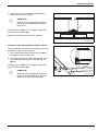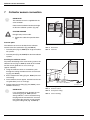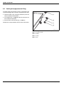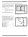
1
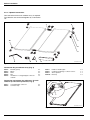
FKT SERIES FLAT PANEL
SOLAR COLLECTORS
FLAT ROOF AND WALL MOUNTED INSTALLATION FOR WORCESTER
SOLAR HEATING SYSTEMS
63043970.01-1.SD
GB
Installation instructions
About this manual
This installation manual contains important
information for the safe and appropriate installation of
the roof mounted solar collectors.
Notes are included with important information for
situations in which there is no danger for persons or
equipment.
These technical documents should be retained in a
safe place. These may also be inspected at the
manufacturer's premises.
The activities described in the installation manual
assume expertise based on completed vocational
training in gas or water-related installation. Only carry
out these installation steps, if you possess these
skills.
B Hand these installation instructions to the
customer.
B Explain to the customer the function and operation
of the related devices.
RECYCLING
At the end of their service life, collectors
may be returned to the manufacturer.
Materials will be recycled in an
environmentally appropriate manner.
2
6 720 613 056 (2006/04)
1
General information
2
Specifications .
3
Safety
. . . . . . . . . . . . . . . . . . . . . . . . . . . . . . . . . . . . . . . . . .4
. . . . . . . . . . . . . . . . . . . . . . . . . . . . . . . . . . . . . . . . . . . . . .5
. . . . . . . . . . . . . . . . . . . . . . . . . . . . . . . . . . . . . . . . . . . . . . . . . . . . .6
3.1 Correct use . . . . . . . . . . . . . . . . . . . . . . . . . . . . . . . . . . . . . . . . . . . . . . .7
3.2 Notes structure . . . . . . . . . . . . . . . . . . . . . . . . . . . . . . . . . . . . . . . . . . . . .8
3.3 Please observe these safety instructions . . . . . . . . . . . . . . . . . . . . . . . . . . . . .9
4
Before installation .
4.1
4.2
4.3
4.4
4.5
4.6
4.7
5
General notes . . . . . . . . . . . . . . . . . . . . . . . .
Component description . . . . . . . . . . . . . . . . . .
Other equipment . . . . . . . . . . . . . . . . . . . . . .
Transport and storage . . . . . . . . . . . . . . . . . . .
Technical documentation . . . . . . . . . . . . . . . . .
Determining the angle of incidence of the collectors
Determining space requirements . . . . . . . . . . . .
. . . . . . . . . . . . . . . . . . . . . 10
. . . . . . . . . . . . . . . . . . . . . 11
. . . . . . . . . . . . . . . . . . . . . 13
. . . . . . . . . . . . . . . . . . . . . 13
. . . . . . . . . . . . . . . . . . . . . 14
. . . . . . . . . . . . . . . . . . . . . 14
. . . . . . . . . . . . . . . . . . . . . 17
Installing flat roof and wall mounting supports
5.1
5.2
5.3
5.4
5.5
6
. . . . . . . . . . . . . . . . . . . . . . . . . . . . . . . . . . . . . . . . . . 10
. . . . . . . . . . . . . . . . . . . . 19
Distances between collector braces for on-site base anchoring . . . . . . . . . . .
Clearances between the collector braces when using loading trays (accessory) .
Stabilising the flat roof supports . . . . . . . . . . . . . . . . . . . . . . . . . . . . . . .
Wall mounting supports - installation . . . . . . . . . . . . . . . . . . . . . . . . . . . .
Installing the profile rails . . . . . . . . . . . . . . . . . . . . . . . . . . . . . . . . . . .
Collector installation .
. . . 20
. . . 22
. . . 24
. . . 26
. . . 28
. . . . . . . . . . . . . . . . . . . . . . . . . . . . . . . . . . . . . . . . 30
6.1 Preparing to install the collectors . . . . . . . . . . . . . . . . . . . . . . . . . . . . . . . . . 31
6.2 Fastening the collectors . . . . . . . . . . . . . . . . . . . . . . . . . . . . . . . . . . . . . . . 32
7
Collector sensor connection .
8
Header connection
8.1
8.2
8.3
8.4
9
. . . . . . . . . . . . . . . . . . . . . . . . . . . . . . . . . . 36
. . . . . . . . . . . . . . . . . . . . . . . . . . . . . . . . . . . . . . . . . . 37
Fitting holder for flow line . . . . . . . . . . . . . . . . . . . . . . . . . . . .
Venting through pressure filling . . . . . . . . . . . . . . . . . . . . . . . .
De-airing through air vent (accessory) at highest point in the system
Connecting two arrays . . . . . . . . . . . . . . . . . . . . . . . . . . . . . .
Final activities .
. . . . . . . . . . 37
. . . . . . . . . . 38
. . . . . . . . . . 39
. . . . . . . . . . 40
. . . . . . . . . . . . . . . . . . . . . . . . . . . . . . . . . . . . . . . . . . . . . 41
9.1 Checking the installation . . . . . . . . . . . . . . . . . . . . . . . . . . . . . . . . . . . . . . 41
9.2 Insulating the connection and header pipes . . . . . . . . . . . . . . . . . . . . . . . . . . 42
10 Quick reference guide for base anchoring and pressure filling
6 720 613 056 (2006/04)
. . . . . . . . 43
3
General information
1
General information
This chapter details which technical rules and
regulations apply to this installation.
i
USER NOTE
Observe all standards and guidelines
applicable to the installation and operation
of this system in your country.
UK
Installation work on roof
The Health and Safety at Work etc
Act 1974
Connection of thermal solar
heating systems
Installation and equipment of DHW
cylinders
EN 12976: Thermal solar heating
system and their components (prefabricated systems).
The Management of Health and Safety
at Work Regulations 1999
ENV 12977: Thermal solar heating
system and their components
The Construction (Health Safety and
(bespoke systems).
Welfare) Regulations 1996
BS 6795: Code of practice for solar
The Construction (Design and
heating systems for swimming pools.
Management) Regulations 1994
BS 5546: 2000 Specification for
installation of hot water supplies for
domestic purposes, using gas-fired
appliances of rated input not
exceeding 70 kW.
BS 6700: 1997 Specification for
design, installation, testing and
maintenance, of servicing supplying
water for domestic use within
buildings and their curtilages.
The Lifting Operations and Lifting
Equipment Regulations 1998
Tab. 1
Technical rules for the installation of thermal solar heating systems (selection) in UK
Lightning protection
If the building height (installation height) exceeds 20 m,
and there is no lightning conductor installed, ask your
local electrical contractor to connect the components on
the roof which conduct electricity with an electrical earth
cable of at least 16 mm2 to the earth bonding.
Special measures regarding lightning protection are not
required for building heights (installation heights) of less
than 20 m.
Where there is a lightning conductor system installed,
ask your local electrical contractor to check the inclusion
of the solar heating system into the lightning protection
system.
4
i
USER NOTE
The installation of the Worcester Solar
System must be carried out in accordance
with the relevant requirements for safety,
current IEE wiring regulations, local
building regulations, building standards
(Scotland) (Consolidation) regulations and
by-laws of the local water company and
health and safety document No 635
(Electricity at Work Regulations 1989).
BS 6795: Latest version
6 720 613 056 (2006/04)
Specifications
2
Specifications
FKT Solar collectors
Certificates
0036
DIN
Length
Width
Height
Clearance between collectors
Fluid content, portrait version
Fluid content, landscape version
Gross absorber surface area
Net absorber surface area
Net weight, portrait version
Net weight, landscape version
Permissible operating pressure of the
collector
Tab. 2
Vf
Vf
AG
m
m
pmax
2,070 mm
1,145 mm
90 mm
25 mm
1.43 l
1.76 l
2.37 m²
2.23 m²
46 kg
47 kg
10 bar
Specifications
6 720 613 056 (2006/04)
5
Safety
3
Safety
This chapter details how the notes for the installation
instructions, as well as the general safety instructions,
necessary for safe and trouble-free operation, are
arranged in this manual.
Safety and user notes, which specifically refer to the
installation, in the installation manual immediately
following the individual installation steps, are found here.
Carefully read the safety instructions before
commencing the installation.
Severe injury and even death, as well as material losses
and environmental damage, may follow if you ignore
safety instructions.
6
6 720 613 056 (2006/04)
Safety
3.1
Correct use
Install components only on roofs with sufficient strength.
Please take the additional roof load per flat roof support,
including solar collector, into consideration. If necessary, ask a structural engineer for assistance.
Only install this system on flat roofs or roofs with a shallow pitch (≤ 25°).
If there is a risk that larger quantities of snow might accumulate behind the collectors (towards the roof ridge),
prevent this by fitting a suitable protective grille.
On roofs with a shallow pitch, attach the system to the
roof on site.
Application conditions for flat roof supports
Only erect the installation set on roofs whose construction can support the weight.
The installation set is suitable for a max. standard snow
load of 2.0 kN/m² and an installation height of
max. 20 m. Using appropriate accessories, the installation set can be used for a max. standard snow load of
3.8 kN/m² and a max. installation height of 100 m.
The flat roof installation set must not be used for fixing
any other objects to the roof. The kit is intended exclusively for the safe fixing of solar collectors.
Conditions at use for wall mounting supports
Only landscape panel orientations are suitable for
wall mounting
Install the wall mounting support only on wall structures
with sufficient structural strength. If necessary, ask a
structural engineer for assistance.
The wall mounting support must only be installed at a
maximum height of 20 m and with a maximum snow
load of 2.0 kN/m².
6 720 613 056 (2006/04)
7
Safety
3.2
Notes structure
Two levels are identified by signal terms:
RISK TO LIFE
WARNING!
Identifies possible dangers which might
lead to serious injury or death if
appropriate care is not taken.
RISK OF INJURY/SYSTEM DAMAGE
CAUTION!
Identifies potentially dangerous situations,
which might lead to mild or slight injuries
or to material losses.
Further symbols identifying dangers and user notes:
RISK TO LIFE
from electric shock.
WARNING!
i
8
USER NOTE
Tip for the optimum utilisation and setting
of the products plus other useful
information.
6 720 613 056 (2006/04)
Safety
3.3
Please observe these safety
instructions
RISK TO LIFE
through a fall or falling parts.
WARNING!
B Ensure you have the correct safety
equipment for working on roofs.
B Take appropriate action to prevent
accidents when working on roofs.
B Whilst working on the roof, take all
necessary precautions against a
possible fall.
B Always wear your personal protective
clothing and safety equipment.
B After completing the installation, always
check the secure positioning of the
installed set and that of the collectors.
RISK OF INJURY
CAUTION!
Injury and operating faults can result from
making changes to the system
construction.
B Never change the system construction.
RISK OF INJURY
CAUTION!
Some parts may cause burns, if the
collector and installation materials are
exposed to solar radiation for longer
periods of time.
B Always wear your personal protective
clothing and safety equipment.
B Cover the collector (e.g. with a covering
sheet - available as an accessory) and
the installation material during the
installation as protection against high
temperatures resulting from solar
irradiation.
6 720 613 056 (2006/04)
9
Before installation
4
Before installation
4.1
General notes
i
USER NOTE
It is recommended that the services of a
roofing company, who are fully experienced in working on roofs and will be
aware of the risk of working at height, are
considered.
Make yourself familiar with the on-site conditions and local regulations before commencing the installation.
Check
B the delivery for completeness and perfect condition.
B the roof structure for sufficient strength and possible
damage (e.g. leaks).
B the building height and determine the type of fixings
required for the flat roof supports (see Chapter 5.3
"Stabilising the flat roof supports", page 24).
B the optimum arrangement of the solar collectors.
Take the solar radiation into consideration
(angle of incidence, southerly orientation). Avoid the
shade of high trees or structures and match the collector array to the shape of the building (e.g. flush
with windows, doors, etc.).
63043970.02-1.SD
Fig. 1
General overview of collector pair – flat roof mounting
B the stability of the support surface. Remove gravel or
similar material.
i
USER NOTE
i
USER NOTE
Only use OEM components and replace
any faulty parts immediately.
Let a professional roofer carry out all difficult roof repairs, particularly weatherproofing of bitumen layers.
63043970.05-1.SD
Fig. 2
10
General overview of collector pair – wall mounted
installation
6 720 613 056 (2006/04)
Before installation
4.2
Component description
4.2.1 Installation set for the collectors
The installation sets are for mounting and fixing the collectors in place.
23
1
4
5
6
5
3
7
8
63043970.03-1.SD
Fig. 3
Installation set for 2 collectors - 1 basic installation set, 1 extended installation set
Basic installation set for each collector array and
for the first collector (Fig. 3):
Item 1:
Item 3:
Item 5:
Item 6:
Item 7:
Item 8:
i
Profile rail
M8 screw × 20
Single-sided collector clamp
M8 nut
Collector brace
Anti-slip protection
2×
6×
4×
4×
2×
2×
Extended installation set for each additional
collector (Fig. 3):
Item 1:
Item 2:
Item 3:
Item 4:
Item 6:
Item 7:
Item 8:
Profile rail
Plug connector with threaded studs
M8 screw × 20
Double-sided collector clamp
M8 nut
Collector brace
Anti-slip protection
2×
2×
3×
2×
2×
1×
2×
USER NOTE
Depending on the use of the flat roof support, auxiliary braces and additional profile rails may be needed, and are dealt
with in the relevant sections.
6 720 613 056 (2006/04)
11
Before installation
4.2.2 Pipework connection
One connection kit for each collector array is required.
The collectors are connected together by a connection
set.
2
1
10
3
4
5
9
Fig. 4
8
7
6
63043969.03-1.SD
Connection kit and connection set (illustration shows 2 portrait collectors)
Connection kit, per collector array (Fig. 4)
Item 2:
Item 3:
Item 4:
Item 5:
Item 6:
Bracket (spare)
Elbow
Olive
Nut
Insulation for corrugated pipe connector
710 mm
2×
2×
2×
2×
1×
Item 7:
Item 8:
Item 9:
Item 10:
Holder for header pipe
Compression fitting for collector sensor
Size 5 spanner
End cap
2×
1×
1×
2×
Connection set between the collectors, for each
collector (in two corner protectors, Fig. 5)
Item 1:
Item 2:
Corrugated pipe connector
Connector clip
2×
4×
2
1
63043966.04-1.SD
Fig. 5
12
Two corner protectors with one connection set
6 720 613 056 (2006/04)
Before installation
4.3
Other equipment
– Spirit level
– Plumb line
– Filling pump
– Vest harness with safety rope
– Pipe insulation
– Scaffolding
– Roofing ladder
– Crane or mobile hoist
i
4.4
USER NOTE
When fitting the roof installation set and
water connection, the only tool reqiured is
the size 5 allen key from the connection
kit.
Transport and storage
Please ensure that the corner protectors are
retained. They contain pipework connection pieces
which are required for installation. All components
are protected by transport packaging.
i
USER NOTE
Dispose of the transport packaging in
an environmentally friendly recycling
system.
Transport protection for collector connections
The collector connections are protected against damage
by rubber caps.
SYSTEM DAMAGE
through damaged sealing faces.
CAUTION!
B Do not remove the rubber caps (Fig. 6,
Item 1) until immediately prior to
installation.
1
Storage
The collectors must be stored in dry conditions.
i
USER NOTE
Do not store collectors outside without
protection from the rain.
63043966.05-1.SD
Fig. 6
6 720 613 056 (2006/04)
Plastic caps on collector connections
13
Before installation
4.5
Technical documentation
The solar heating system consists of various components (Fig. 7). Installation, operation and maintenance
documentation is provided for each component. Accessories may be accompanied by a separate document.
Item 1:
Collector: instructions for roof installation
are enclosed with the connection kit
Item 2:
Pump station: instructions enclosed with the
complete station
Item 3:
Solar Controller: instructions are enclosed
with the controller.
Item 4:
DHW Cylinder: instructions enclosed with the
DHW cylinder.
4
1
3
2
6720613577.00-1.SD
Fig. 7
4.6
Solar heating system components and technical
documentation
Determining the angle of incidence of the collectors
The collectors' angle of incidence to be selected depends on the desired area of application. It can be adjusted using the telescopic rails (Fig. 8).
4.6.1 Determining the area of application
The different areas of application of solar heating systems provide angles of incidence that ensure an optimum solar yield for every season.
Applications
DHW
Domestic hot water + central heating
Domestic hot water + swimming pool
Domestic hot water + central heating +
swimming pool
Tab. 3
14
Angle of incidence
range
30 – 45°
45 – 60°
30 – 45°
45 – 60°
63043970.06-1.SD
Fig. 8
Angle of incidence of the collector on a flat roof
Area of application, angle of incidence range
6 720 613 056 (2006/04)
Before installation
4.6.2 Sloping roofs
On roofs that slope slightly in a southerly direction, the
pitch angles are deducted from the angle of incidence.
On roofs that slope slightly in a northerly direction, the
pitch angles are added to the angle of incidence (Fig. 9).
1
RISK TO LIFE
WARNING!
SYSTEM DAMAGE
CAUTION!
45°
If there is a risk that larger quantities of
snow might accumulate behind the collectors (towards the roof ridge), prevent this
by fitting a suitable protective grille on
site.
2
45°
30°
30°
15°
15°
3
63043970.07-1.SD
Fig. 9
Angle of incidence of the collector on a flat roof
through strong wind. On sloping flat roofs
the flat roof supports must be secured on
site.
Item 1: Angle of incidence (absolute angle to the horizontal
plane)
B Ask a roofing contractor to carry out
the installation on sloping flat roofs.
Item 3: Roof pitch
Item 2: Collector angle of inclination
4.6.3 Walls
The landscape collector braces can be used as flat roof
supports or wall-mounting supports.
RISK TO LIFE
WARNING!
from falling collectors, due to incorrect
use.
45°
30°
B The collector angle of incidence
(Fig. 10, Item 1) to the horizontal must
be between 45° and 60° (or the angle
of inclination Fig. 10, Item 2 of the collectors must be between 30° and 45°)
2
45°
1
60°
63043970.27-1.SD
Fig. 10
Angle of incidence of the collector on a wall
Item 1: Angle of incidence (absolute angle to the horizontal
plane)
Item 2: Collector angle of inclination
6 720 613 056 (2006/04)
15
Before installation
4.6.4 Fitting telescopic rails
Different angles of incidence can be set using the telescopic rails.
B Select holes on the upper and lower telescopic rails
as shown in Fig. 12 and Fig. 13.
B Insert telescopic rails into each other and fasten with
M8 × 20 screw (Fig. 11).
1.
63043970.08-1.SD
Fig. 11
i
Connecting telescopic rails
USER NOTE
30°
For vertical installation of a collector with
an angle of inclination of 30° to 60°, use
the uppermost hole on the lower telescopic rail (Fig. 12, Item 1).
35°
40°
45°
For an angle of inclination of 25°, you
must shorten the top of the lower rail by
140 mm and use the lower hole (Fig. 12,
Item 2).
50°
55°
60°
25°
140 mm
1
2
63043970.39-1.SD
Fig. 12
16
Adjust angle of inclination for portrait collectors
6 720 613 056 (2006/04)
Before installation
i
USER NOTE
35°
40°
For landscape installation of a collector
with an angle of inclination of 35° to 60°,
use the uppermost hole on the lower telescopic rail (Fig. 13, Item 3).
45°
50°
55°
60°
For an angle of inclination of 25° and 30°,
you must shorten the top of the lower rail
by 140 mm and use the lower hole
(Fig. 13, Item 2).
1
1
1
25°
30°
1
140 mm
RISK TO LIFE
WARNING!
3
from falling collectors, due to incorrect
use.
B For wall-mounted installation, use only
the positions for the collector angles of
inclination 30°, 35°, 40° and 45°
(Fig. 13, Item 1).
2
63043970.40-1.SD
4.7
Determining space requirements
Fig. 13
Adjusting angle of inclination for landscape collectors
4.7.1 Ascertaining the clearance between collector
arrays
The minimum spacing between the collector arrays is
determined by the angle of inclination of the collector.
i
USER NOTE
When using multi-row arrays, note that
the clearance X (Fig. 14) between the arrays must be large enough to avoid shadows falling over adjacent collectors.
Maintain the clearance stated in the tables or calculate
the require clearance (Technical Guide).
X
Angle of inclination – collector
Tab. 4
Clearance X
Portrait
installation
Landscape
installation
25°
4.74 m
2.63 m
30°
5.18 m
2.87 m
35°
5.58 m
3.09 m
40°
5.94 m
3.29 m
45°
6.26 m
3.46 m
50°
6.52 m
3.61 m
55°
6.74 m
3.73 m
60°
6.90 m
3.82 m
63043970.09-1.SD
Fig. 14
Shadow – clearance X
Dependency of clearance X on the angle of
incidence and the minimum altitude of the sun (17°)
6 720 613 056 (2006/04)
17
Before installation
4.7.2 Estimating your space requirements
SYSTEM DAMAGE
CAUTION!
through wind, eddies and pressure peaks
around the roof edges.
B Before commencing the installation,
ensure that at least one metre is allowed between the flat roof supports
and the edge of the roof (Fig. 15).
>1 m
>1 m
63043970.41-1.SD
Fig. 15
Distance from the edge of the roof
Allow sufficient installation space for the different forms
of installation (landscape, portrait).
These dimensions (Tab. 5 and Tab. 6) relate to the roof
surface area which must be available.
The quoted dimensions are simply the width of the collector array. In addition, allow at least 0.5 m on either
side of the collector array for pipework.
B
A
63043970.10-1.SD
Fig. 16
Space requirements for portrait collectors:
Number
Dimension
of collectors
A
2
2.34 m
Space requirements for landscape collectors:
Angle of
inclination
25°
Dimension
B
1.84 m
Number
of collectors
2
Dimension
A
4.18 m
Angle of
inclination
25°
Dimension
B
1.06 m
6.28 m
30°
1.02 m
3
3.51 m
30°
1.75 m
3
4
4.68 m
35°
1.68 m
4
8.38 m
35°
0.96 m
5
5.85 m
40°
1.58 m
5
10.48 m
40°
0.91 m
6
7.02 m
45°
1.48 m
6
12.58 m
45°
0.85 m
7
8.19 m
50°
1.48 m
7
14.68 m
50°
0.85 m
8
9.36 m
55°
1.48 m
8
16.78 m
55°
0.85 m
9
10.53 m
60°
1.48 m
9
18.88 m
60°
0.85 m
10
11.70 m
10
20.98 m
Tab. 5
18
Space requirements – collector array – portrait
version
Space requirement for portrait installed collectors
Tab. 6
Space requirements for landscape installed
collectors
6 720 613 056 (2006/04)
Installing flat roof and wall mounting supports
5
Installing flat roof and wall mounting supports
RISK TO LIFE
WARNING!
Whilst working on the roof, take all necessary precautions against a possible fall.
RISK OF INJURY
through a fall or falling parts.
WARNING!
B Take appropriate action to prevent accidents when working on roofs.
B Always wear your personal protective
clothing and safety equipment.
i
63043970.11-1.SD
USER NOTE
Fig. 17
Portrait flat roof supports for 2 collectors
Please observe all national and local accident prevention regulations, as well as
the safety instructions in this manual
when working on roofs.
Ensure sufficient stability at the installation surface, and
removing any gravel and similar material.
i
USER NOTE
To protect the roof skin, lay commercially
available building protection mats, onto
which you can position the profiles. The
sealing membrane must not be damaged.
This installation method also applies to the flat roof
support for landscape collectors.
The following describes the installation of flat roof supports for portrait collectors. The landscape version is installed in the same way.
Notes identify any variations.
63043970.23-1.SD
Fig. 18
6 720 613 056 (2006/04)
Landscape flat roof supports for 2 collectors
19
Installing flat roof and wall mounting supports
5.1
Distances between collector braces
for on-site base anchoring
The distances between the collector braces (middle/middle, in mm) depend on:
– the collector version (portrait, landscape)
– and the maximum snow and wind loads
i
USER NOTE
You must strictly observe the clearances
between the collector braces so that the
profile rails can still be installed at a later
stage.
980
980
5.1.1 Basic version
63043970.44-1.SD
Two collector braces are required for the first collector.
For every additional portrait collector, another collector
brace is required (Fig. 19). For every additional landscape collector, two further collector braces are required
(Fig. 21).
Fig. 19
Basic version for 2 portrait collectors
The basic version can be used for the following loads:
– building height max. 20 m (installation height)
– max. 2.0 kN/m² snow load
980
last
collector
1170
x collectors
980
first
collector
63043970.13-1.SD
Fig. 20
Basic version for 3 – 10 portrait collectors
1820
275
1820
63043970.42-1.SD
Fig. 21
20
Basic version for 2 landscape collectors
6 720 613 056 (2006/04)
Installing flat roof and wall mounting supports
5.1.2 Version with auxiliary brace (accessory)
For greater loads, an auxiliary brace (and additional profile rails, page 29) is required for portrait installation for
the second and all further collectors (Fig. 22). This version can be used for the following loads:
– Building height max. 100 m (installation height)
– max. 3.8 kN/m² snow load
i
USER NOTE
For landscape installation, a max. building height of 100 m and a max. snow load
of 3.8 kN/m² are permitted using the basic
version (Fig. 21, provided that an additional rail is fitted, page 29).
980
190
980
190
980
63043970.14-1.SD
Fig. 22
Auxiliary braces for 3 portrait collectors
63043970.14-1.SD
6 720 613 056 (2006/04)
21
Installing flat roof and wall mounting supports
5.2
Clearances between the collector
braces when using loading trays
(accessory)
The distances between the collector braces (middle/middle, in mm) depend on:
– the collector version (portrait, landscape)
– and the maximum snow and wind loads.
For portrait installation, an auxiliary brace must be erected for the 4th, 7th and 10th collectors (Fig. 23, Item 1).
i
USER NOTE
Strictly observe the clearances between
the collector braces so that the profile
rails can be installed.
5.2.1 Basic version
The basic version can be used for the following loads:
– Building height max. 20 m (installation height)
– max. 2.0 kN/m² snow load
Number of
collectors
4
Dim. A
Dim. B
Dimension C
381 mm
-
-
5
381 mm
-
-
6
571 mm
-
-
7
571 mm
381 mm
-
8
571 mm
381 mm
-
9
571 mm
571 mm
-
10
571 mm
571 mm
381 mm
Tab. 7
Distances between auxiliary braces
1
10.
980
9.
C
1
1
980
8.
7.
980
980
6.
B
980
5.
980
4.
980
3.
A
980
2.
1.
980
980
63043970.15-1.SD
Fig. 23
22
Basic version for up to 10 portrait collectors (in mm)
6 720 613 056 (2006/04)
Installing flat roof and wall mounting supports
i
USER NOTE
Landscape installation can be carried out
using only the auxiliary brace (accessory).
For landscape installation, 3 collector braces must be fitted for each collector (Fig. 24).
980
980
135
980
980
63043970.16-1.SD
Fig. 24
Basic version for 2 landscape collectors
5.2.2 Version for maximum loads (accessory,
Fig. 25)
For greater loads, ropes (page 25) and additional rails
(page 29) are also required. This version can be used
for the following loads:
– Building height max. 100 m (installation height)
– max. 3.8 kN/m² snow load
i
USER NOTE
For distances between the landscape collector braces for maximum loads, refer to
Fig. 24.
980
190
980
190
980
63043970.14-1.SD
63043970.14-1.SD
Fig. 25
Version for maximum loads, 3 portrait collectors
63043970.14-1.SD
6 720 613 056 (2006/04)
23
Installing flat roof and wall mounting supports
5.3
Stabilising the flat roof supports
The following details refer to a single collector. These
details are based on DIN 1055, part 4 "Design loads for
buildings".
Individual flat roof supports may be secured in the following three ways to prevent slippage or tipping of the
structure due to the effect of the wind:
– Securing flat roof supports with anchor bolts (onsite).
– Weigh down flat roof supports with concrete slabs,
gravel or similar material (loading trays required).
– Weigh down flat roof supports with concrete slabs,
gravel or similar material (loading trays required) and
make more secure using rope as necessary.
For all methods, please consider the structural integrity
of the roof.
i
USER NOTE
i
USER NOTE
Using gravel in the loading trays, a maximum load of 320 kg is possible per collector (Tab. 8).
For the following table, please also consider the clearances and number of additional collector braces (Chapter 5.1
"Distances between collector braces for
on-site base anchoring").
Stabilising a collector
Height of building
Wind velocity
0 m to 8 m
above 8 m up to 20 m
above 20 m up to
100 m 1
Tab. 8
Weighting
Number and type
of screws 2
Weight
(e.g. concrete slabs)
2 × M8/8.8
2 × M8/8.8
3 × M8/8.8
270 kg
450 kg
–
Ropes
Securing against
Securing against
tipping
slippage
Weight
Maximum rope
(e.g. concrete
tension
slabs)
180 kg
1.6 kN
320 kg
2.5 kN
450 kg
3.3 kN
Values to stabilise one collector
1
With additional rail only
2
Per collector brace
24
102 km/h
129 km/h
151 km/h
Base anchor
6 720 613 056 (2006/04)
Installing flat roof and wall mounting supports
5.3.1 Securing flat roof supports on site with base
anchoring
1
You can fasten the flat roof supports with anchor bolts.
As an example, we describe fastening onto girders
(Fig. 26, Item 3).
Design the substructure so that the collectors can withstand the snow loads and wind forces placed upon
them.
2
In addition, a means of fixing should be provided on site
that stabilises the structure and prevents damage to the
roof.
3
SYSTEM DAMAGE
63043970.46-1.SD
CAUTION!
through modifications to the design of the
flat roof supports.
Fig. 26
563 3)
(35
563 )
3
(35
Flat roof support on girders, dimensions in mm
(value in brackets = landscape version)
B For example, never drill the flat roof
support profiles.
B Transfer the lower profile hole clearances (Fig. 26,
Item 2) onto the girders, and drill the corresponding
holes.
1
B Insert screws (see Tab. 8 and Fig. 26, Item 1)
through the profiles and girders and screw tight with
nuts and washers.
3
2
5.3.2 Securing flat roof supports with weights
B Erect collector braces (see Chapter 5.1 "Distances
between collector braces for on-site base anchoring").
B Insert loading trays (Fig. 27, Item 2) into lower profiles (Fig. 27, Item 1) and into each other (Fig. 27,
Item 3).
B Insert concrete slabs or similar into loading trays
(for required weight, see Tab. 8).
63043970.19-1.SD
Fig. 27
4 loading trays per collector
5.3.3 Providing extra security for the flat roof
supports using rope
You may also additionally secure the weighted flat roof
support with ropes.
Select the rope depending on the expected loads
(see Tab. 8).
1
1
B Fasten each collector on site to the screw on the lower profile and to a suitable point on the roof, using at
least 2 wire ropes (Fig. 28, Item 1).
63043970.20-1.SD
Fig. 28
6 720 613 056 (2006/04)
Flat roof support with ropes
25
Installing flat roof and wall mounting supports
5.4
Wall mounting supports - installation
The landscape collector braces can also be used for
wall-mounted installation.
RISK TO LIFE
WARNING!
from falling collectors, due to incorrect
use.
B Only landscape collector braces are
allowed for wall-mounted installation.
B Collectors may only be installed on
walls of buildings with a height up to
20 m (wind velocity = 129 km/h) and a
snow load of up to 2.0 kN/m².
B Each collector brace must be fastened
to the holes provided, using 3 screws
(provided by customer) (Tab. 9).
B Install only on a sealed, windproof outside wall.
63043970.05-1.SD
Fig. 29
Wall mounting support
B Before installing the wall mounting
support, check the load-bearing capability of the fixing wall (i.e. of the wall
base). If necessary, ask a structural
engineer for assistance.
B Never modify the wall mounting structure.
B Never place objects in the space underneath the wall mounting support.
B Never fit facing to the collectors.
B Fasten as follows:
Wall structure 3
Steel-reinforced concrete min. B25
(min. 120 mm)
Steel base structure (e.g. girder)
Tab. 9
Fixings per collector brace
Distance from the edge
of the wall
3 × UPAT MAX Express anchors, type MAX 8 (A4)1 or similar
> 100 mm
and 3 × washers 2
3 × Hilti HST-HCR-M8 1 or HST-R-M8 1 or similar and
> 100 mm
3 × washers 2
3 × M8 (4.6) and 2 × washers 2
–
Fasteners
1
A tensile strength of 1.63 kN or a shear strength of at least 1.56 kN must be able to be applied to each fixing.
2
3 × Screw diameter = outside diameter of washer.
3
Brickwork on request
B Use 3 screws to fasten each collector brace to the
wall (see Tab. 9, Fig. 30, Item 1).
26
6 720 613 056 (2006/04)
Installing flat roof and wall mounting supports
980
980
135
980
980
1
63043970.30-1.SD
Fig. 30
Fastening collector braces to the wall (for 2 collectors, dimensions in mm)
6 720 613 056 (2006/04)
27
Installing flat roof and wall mounting supports
5.5
Installing the profile rails
The profile rails must be joined together using plug connectors. Each collector is provided with an upper and
lower profile rail.
1
2
5.5.1 Connecting profile rails
B Push plug connector (Fig. 31, Item 1) as far as it will
go into both profile rails (Fig. 31, Item 2).
B To lock, tighten both fitted M10 threaded studs
(Fig. 31, Item 3) in the plug connector using a size
5 spanner.
3
63043965.33-1.SD
Fig. 31
5.5.2 Installing profile rails
Connecting profile rails
1
2 3
Positioning the profile rails depends on
– whether they are being installed portrait or landscape
– and on the clearances between the collector braces.
If using base anchoring, begin fastening the profile rails
as follows:
Base anchoring
Basic version
Auxiliary brace
portrait:
Align with middle hole Align with second
on plug connector
slotted hole from right
(Fig. 32, Item 1)
(Fig. 32, Item 3)
landscape:
Align with third slotted
hole from right
(Fig. 32, Item 2)
--
63043970.43-1.SD
Fig. 32
Tab. 10 Aligning the lower and upper profile rails when using
base anchoring
1
Aligning the profile rails for on-site base anchoring
3
2
If using loading trays, begin fastening the profile rails as
follows:
Loading trays
2 collectors
3 to 10 collectors
portrait:
Align with middle hole Align with sixth sloton plug connector
ted hole from right
(Fig. 33, Item 1)
(Fig. 33, Item 2)
landscape:
Align with second slot- Align with second
ted hole from right
slotted hole from right
(Fig. 33, Item 3)
(Fig. 33, Item 3)
Tab. 11 Aligning the lower and upper profile rails when using
loading trays
28
63043970.45-1.SD
Fig. 33
Aligning the profile rails for loading trays
6 720 613 056 (2006/04)
Installing flat roof and wall mounting supports
B Lightly tighten the pre-assembled profile rails
(Fig. 34, Item 2) with M8 x 20 bolts (Fig. 34, Item 1)
so that the profile rails can still be aligned.
B Align the sides of the upper and lower profile rails.
B Tighten bolts.
1
2
63043970.21-1.SD
Fig. 34
Fitting profile rails (for two portrait collectors in this
example)
5.5.3 Fitting additional profile rails (accessory)
If the collector array is exposed to greater loads (building
or installation height of over 20 m and/or snow load of
over 2.0 kN/m²), additional rails must be fitted.
B Fasten additional profile rails as described in
Chapter 5.5.2 "Installing profile rails", using the middle hole on the profile (Fig. 35, Item 1).
1
B Align sides of the profile rails.
B Tighten bolts.
63043970.25-1.SD
Fig. 35
Fitting additional profile rails
5.5.4 Installation of anti-slip protection
To prevent the collectors from slipping, you must fasten
two anti-slip protectors to the lower profile rails for each
collector.
1
3
B Push each anti-slip protector (Fig. 36, Item 3) into
the innermost slotted holes (Fig. 36, Item 1) over the
profile rails until it clicks into place (Fig. 36, Item 2).
2
63043970.24-1.SD
Fig. 36
Attaching anti-slip protection
Item 1: Fixing holes for the anti-slip protection
Item 2: Clicking the anti-slip protection into place
Item 3: Anti-slip protection
6 720 613 056 (2006/04)
29
Collector installation
6
Collector installation
Observe the following safety and user instructions when
commencing the collector installation.
RISK TO LIFE
through a fall or falling parts.
WARNING!
B Take appropriate action to prevent accidents when working on roofs.
B Whilst working on the roof, take all
necessary precautions against a possible fall.
B Always wear your personal protective
clothing and safety equipment.
B After completing the installation, always check that the installed set and
the collectors are fastened securely.
63043970.02-1.SD
Fig. 37
Flat roof installation: 2 collectors
Fig. 38
Wall mounted installation
RISK OF INJURY
through interruption of work.
CAUTION!
B Secure the collectors against falling.
B Stabilise the collector array.
SYSTEM DAMAGE
through damaged sealing faces.
CAUTION!
30
B Do not remove the rubber caps on the
collector connections until immediately prior to installation.
63043970.05-1.SD
i
USER NOTE
i
USER NOTE
Use lifting equipment as used by roofing
contractors, sufficiently strong 3-point
suction handles or special carry handles
for the installation (for easier lifting).
Unsecured collectors may fall during handling and installation.
6 720 613 056 (2006/04)
Collector installation
6.1
1
Preparing to install the collectors
Before beginning actual installation on the roof, preassemble the locking caps on the ground to make work on
the roof easier.
4
To secure the locking caps (and later the corrugated
pipe connectors and connecting pipes as well), attach
brackets to the connections.
SYSTEM DAMAGE
CAUTION!
through leaks in the collector connections.
The corrugated pipe connectors, connecting pipes and collector connections
must not display any signs of damage or
contamination.
B The collector connections have had
special grease applied in the factory to
make installation easier. Do not use
any other grease.
4
1
2
3
63043966.09-1.SD
Fig. 39
Water connection (right) up to max. 5 collectors
Item 1: Corrugated pipe connector
Item 2: Flow line
Item 3: Return line
Item 4: Locking cap
1
6.1.1 Pipework connections
The collectors must be installed in such a way that the
sensor bushs for taking up the collector sensor (Fig. 40,
Item 1) are at the top.
i
USER NOTE
The water connection pipes can be connected on the right (Fig. 39) or left
(Fig. 40). In this manual, the connection
pipes are shown on the right.
The pipework in the collector is designed as a double
meander, which enables you to carry out two different
water connections:
63043966.10-1.SD
Fig. 40
Water connection (left) up to max. 5 collectors
Fig. 41
Two-way pipework connections
Single-sided connection of up to 5 collectors
Up to 5 collectors can be connected to one side of a collector array (Fig. 39 and Fig. 40).
Two-way connection of up to 9 collectors
If there are more than 5 collectors installed in one
collector array, the water connection must be two-way
(Tichelmann principle, Fig. 41).
The two-way connection can also be made if there are
fewer than 6 collectors (Fig. 41).
If more than 9 collectors are required then a further AGS
pump station is required.
6 720 613 056 (2006/04)
63043966.08-1.SD
31
Collector installation
6.1.2 Fitting the end cap
Not all the connections are needed when connecting a
collector array, so those that are not used must be
closed.
B Remove rubber caps (transport protection) from the
relevant collector connections.
B Push end cap with the O-rings (Fig. 42, Item 3) onto
the collector connection.
3
1
B Push bracket (Fig. 42, Item 2) over the end cap and
collector connection to secure the connection.
SYSTEM DAMAGE
2
from unsecured end caps.
CAUTION!
6.2
B Secure each end cap with a bracket
(Fig. 42, Item 1).
63043966.12-2.SD
Fig. 42
Securing end cap with bracket
Fastening the collectors
The collectors are fastened to the profile rails using the
single-sided collector clamps (Fig. 43, Item 2) at the beginning and end of a collector array, and double-sided
clamps (Fig. 43, Item 1) between each collector.
2
1
In addition, the anti-slip protectors (Fig. 43, Item 3) prevent the collector from slipping.
i
USER NOTE
The plastic parts on the collector clamps
do not have any support function. They
are simply intended to make installation
easier.
3
Fig. 43
63043970.26-1.SD
Fasteners for the collector
Fitting the single-sided collector clamp on the right
B Push single-sided collector clamps (Fig. 44, Item 1)
into the profile rails at the right-hand end of the collector array until they click into place in the first slotted hole on the profile rails.
i
1
USER NOTE
Do not fit the single-sided collector
clamps to the left-hand side of the collector array until the last collector has been
installed.
63043970.31-1.SD
Fig. 44
32
Pushing on the single-sided collector clamp
6 720 613 056 (2006/04)
Collector installation
Putting the first collector in place
Lay the collector on the profile rails in such a way that
the sensor bush to receive the collector sensor is at the
top. Begin by laying the collectors on the right-hand side
of the profile rails.
1
RISK OF INJURY
CAUTION!
Install collectors with at least one assistant.
B Place the first collector onto the profile rails and allow
it to slide into the anti-slip protectors (Fig. 45, Item 2)
(Fig. 45).
The lower collector edge must lie in the opening of the
anti-slip protector (Fig. 45, Item 1).
2
63043970.32-1.SD
Fig. 45
Laying the first collector on the profile rails
B Carefully push collector (Fig. 46, Item 1) up against
the single-sided collector clamp and align horizontally.
1
B Screw in single-sided collector clamp using size 5
spanner (Fig. 46, Item 2).
i
USER NOTE
2
When the screw is tightened, the plastic
guide at the pre-determined cut-off points
breaks away and can be discarded.
The grip (Fig. 46, Item 2) on the collector clamp now
grips the lower collector edge.
63043965.45-1.SD
Fig. 46
Single-sided collector clamp screwed in place
Inserting a double-sided collector clamp
B Insert the double-sided collector clamp, nut first, into
the opening made by the profile rail and plug connector so that the plastic spacer (Fig. 47, Item 1) surrounds the profile rail.
B Push double-sided collector clamp up against the
collector frame.
1
i
USER NOTE
1
Do not tighten the screw until the second
collector has been pushed up against the
double-sided collector clamp.
63043969.02-1.SD
Fig. 47
6 720 613 056 (2006/04)
Fitting a double-sided collector clamp
33
Collector installation
Fitting corrugated pipe connectors to the first
collector
B Remove the rubber caps from the connections.
B Push corrugated pipe connectors (Fig. 48, Item 1)
onto the left-hand connections on the first collector.
B Push bracket (Fig. 48, Item 2) over the corrugated
pipe connector and collector connection to secure
the connection.
1
2
63043966.11-1.SD
Fig. 48
Fitting corrugated pipe connectors to the first
collector
Putting the second collector in place
B Place the second collector onto the profile rails and
allow it to slide into the anti-slip protectors.
SYSTEM DAMAGE
CAUTION!
2
1
through damaged corrugated pipe
connectors.
B Do not use any tools, e.g. pliers
(Fig. 49, Item 2). These could render
the corrugated pipe connector
unusable.
B Push the second collector on to the first in such a way
that the collector connections are pushed into the
preassembled corrugated pipe connectors (Fig. 49,
Item 1) on the first collector.
3
2
63043966.15-1.SD
Fig. 49
Pushing second collector towards the first
B Place second bracket (Fig. 49, Item 3) over the
corrugated pipe connector and collector connection.
SYSTEM DAMAGE
CAUTION!
through unsecured corrugated pipe
connectors and end caps.
B Secure each end cap with one bracket
and each corrugated pipe connector
with two brackets (Fig. 50, Item 1).
1
63043966.16-1.SD
Fig. 50
34
Corrugated pipe connector secured with brackets
6 720 613 056 (2006/04)
Collector installation
B Tighten the screw on the double-sided collector
clamp using the size 5 spanner.
i
USER NOTE
When the screw is tightened, the plastic
lugs at the pre-determined cut-off points
break away.
1
The grip (Fig. 51, Item 1) on the collector clamp now
grips the lower collector edge.
Repeat the procedure for all the other collectors.
63043965.48-1.SD
Fig. 51
Double-sided collector clamp between two collectors
Fitting the single-sided collector clamp on the left
Once all collectors are fitted, the two remaining one-sided collector clamps can be attached.
2
B Push single-sided collector clamp (Fig. 52, Item 1)
into upper and lower profile rails.
B Push collector clamp up against the collector frame
and screw in place using size 5 spanner (Fig. 52,
Item 2).
1
The grip (Fig. 52, Item 2) on the collector clamp now
grips the lower collector edge.
i
USER NOTE
When the screw is tightened, the plastic
guide at the pre-determined cut-off points
breaks away and can be discarded.
6 720 613 056 (2006/04)
63043970.34-1.SD
Fig. 52
Single-sided collector clamp (left)
35
Collector sensor connection
7
Collector sensor connection
i
USER NOTE
B
The collector sensor is supplied with the
solar controller.
A
Observe the installation location for single
or dual row collector systems (Fig. 53).
SYSTEM DAMAGE
through faulty sensor cable.
CAUTION!
1 2
B Protect the cable from possible damage.
Insertion point
The collector sensor must be fitted in the collector
nearest to the flow connection (Fig. 53, Item 2).
– Insertion point (Fig. 53, Item A) for single row collector systems.
1 2
63043966.25-1.SD
Fig. 53
Collector sensor installation location (schematic)
Item 1: Return line
Item 2: Flow line
– Insertion point (Fig. 53, Item B) for dual row collector
systems.
Installing the collector sensor
For perfect functioning of the solar heating system, the
collector sensor (Fig. 54, Item 1) needs to be inserted
into the sensor guide tube as far as it will go
(approx. 250 mm).
B Using the collector sensor or screwdriver, push
through the sealing membrane on the sensor bushing (Fig. 54, Item 3).
3
B Insert collector sensor approx. 250 mm into the sensor guide tube (as far as it will go).
B Tighten compression fitting (Fig. 54, Item 2), counterhold if necessary.
i
36
USER NOTE
1
2
B Screw compression fitting (Fig. 54, Item 2) into sensor bushing.
Kollektor
250 mm
63043966.26-1.SD
Fig. 54
Inserting the collector sensor into the collector
Item 1: Collector sensor
Item 2: Compession fitting
If you accidentally push through the sensor bushing (Fig. 54, Item 3) on the
wrong collector, it can be resealed using
the plug from the connection kit. You must
first remove the nut in the sensor bushing
using the cable gland (Fig. 54, Item 2).
Item 3: Sensor bushing
6 720 613 056 (2006/04)
Header connection
8
Header connection
Information on laying the header pipes can be found in
the complete station installation instructions.
SYSTEM DAMAGE
CAUTION!
from leaks in the collector connection,
due to movements caused by heat.
B Feed the on-site flow line (Fig. 55,
Item 1) alongside the collector, rather
than vertically downwards.
1
2 1
63043969.01-1.SD
Fig. 55
Feeding header pipes to the collector array
Item 1: Flow line
Item 2: Return line
8.1
Fitting holder for flow line
Use the holder to fasten the insulated flow line to the collector.
i
User note:
We recommend commercially available
hose clamps (Fig. 56, Item 1) for fastening the header to the M8 thread on the
holder (Fig. 56, Item 2).
2
1
Select the diameter on the hose clamp
according to the outside diameter of the
flow line, incl. insulation.
3
B Place holder (Fig. 56, Item 3) onto collector frame
and tighten with size 5 spanner.
B Fasten insulated header to holder on site.
63043970.35-1.SD
Fig. 56
Fastening holder to the collector frame
Item 1: Hose clamp (on building)
Item 2: M8 thread
Item 3: Holder
6 720 613 056 (2006/04)
37
Header connection
8.2
Venting through pressure filling
If venting of the solar heating system is carried out using
a pressure filling pump, no vent is required on the roof.
B Remove rubber caps (transport protection) from the
relevant collector connections.
1
B Push elbow (Fig. 57, Item 2) with olive and union nut
onto collector connection.
B Secure elbow with bracket (Fig. 57, Item 1).
2
Perform the same procedure with the return connection.
3
4
63043969.04-1.SD
Fig. 57
Fitting flow line (with no vent on roof)
Item 1: Connector clip
Item 2: Elbow
Item 3: Olive
Item 4: Nut
38
6 720 613 056 (2006/04)
Header connection
8.3
De-airing through air vent (accessory) at highest point in the system
If you intend to vent the solar heating system with an
automatic air-vent valve (accessory) at the highest point
of the system, run the flow line rising to the air-vent valve
(Fig. 58, Item 2) and the return line rising to the collector
array (Fig. 58).
2
1
Avoid frequent changes in direction.
i
User note:
For each change of direction downwards
and each new rise, install an additional air
pot with air vent.
If you cannot provide an automatic air vent valve due to
space restrictions, install a manual air vent valve.
63043966.20-1.SD
Fig. 58
View – air pot with vent valve for flow connection
Item 1: Collector sensor
Item 2: Automatic air vent valve on roof
Function of the grub screw and weather protection
cap on the automatic air vent valve
The solar heating system is vented through the opened
grub screw. When in operation, the weather protection
cap (Fig. 59, Item 1) must always be positioned over
the grub screw to prevent moisture entering through the
opened grub screw into the solar heating system).
10
Open the air vent valve by unscrewing the grub screw
one full revolution.
8
Universal air vent set (Fig. 59):
7
Item 1:
Item 2:
Item 3:
Item 4:
Item 5:
Item 6:
Item 7:
Item 8:
Item 9:
Item 10:
Item 11:
Weather protection cap
Automatic air vent
Ball valve
Gasket
Vent pot
Double threaded fitting with O-ring
Threaded fitting
Union nut
Gasket
Large diameter washer
Clamping disc
6 720 613 056 (2006/04)
1×
1×
1×
1×
1×
1×
1×
2×
1×
1×
1×
11
1
2
9
3
4
5
6
63043966.21-1.SD
Fig. 59
Universal air vent set
39
Header connection
Fitting the air vent
1
B Firmly screw threaded fitting (Fig. 60, Item 6) and
double threaded fitting (Fig. 60, Item 4) into air pot
(O-ring gasket).
B Push air pot (Fig. 60, Item 5) and fitting onto collector
connection and secure with clip.
B Connect header pipe to the compression fitting
(22 mm) (Fig. 60, Item 2).
6
Fig. 60
4
5
3 2
63043969.05-1.SD
Connecting the air vent
Item 1: Connector clip
Item 2: Union nut for 22 mm compression fitting
Item 3: Olive
Item 4: Double threaded fitting with O-ring
Item 5: Air pot
Item 6: Threaded fitting
8.4
Connecting two arrays
If connecting two collector arrays (Fig. 61, Item 1) you
will need a second connection kit.
B Fit individual parts as described in Chapter 8.2 "Venting through pressure filling".
B Make on-site connection between collector arrays
using copper pipe.
1
1
63043969.06-1.SD
Fig. 61
40
Two collector arrays, one behind the other
6 720 613 056 (2006/04)
Final activities
9
Final activities
9.1
Checking the installation
SYSTEM DAMAGE
CAUTION!
through corrosion if water remains in the
solar heating system for an extended period after it has been flushed or after a
pressure test.
B Start up the solar heating system immediately after flushing/pressure test
with solar fluid (for instructions on
flushing/pressure test see pump station instructions). Otherwise, carry out
flushing/pressure test later.
i
USER NOTE
Do not carry out the final insulating work
until the appropriate checks have been
performed.
Checks
1.
Corrugated pipe connector, end caps and
connecting pipe bends secured with clips?
2.
All collector braces connected to profile
rails?
3.
Anti-slip protection installed and clicked into
place in profile rails?
4.
Sensor inserted as far as it will go and secured with compression fitting?
5.
Pressure test carried out and all connections
leak-proof (see pump station instructions)?
i
USER NOTE
If you are venting the solar heating system with an automatic air-vent valve (accessory), you must close the ball valve
after the venting procedure (see pump
station installation instructions).
6 720 613 056 (2006/04)
41
Final activities
9.2
Insulating the connection and header
pipes
B Cut enclosed insulation (710 mm long) into 88 mm
lengths and place around the corrugated pipe connectors between the collectors.
Insulation of the header pipes in internal or external
installations
– For the insulation of external pipework, use only UV
and high temperature resistant insulating materials,
rated to 150 °C.
– For the insulation of internal pipework, use only high
temperature resistant insulating materials, rated to
150 °C.
– Make the insulation bird-proof.
42
6 720 613 056 (2006/04)
Quick reference guide for base anchoring and pressure filling
10 Quick reference guide for base anchoring and pressure filling
These instructions are only intended as an overview of
the work to be carried out. You MUST follow the detailed
descriptions for the work on the pages mentioned, and
obey all safety and user instructions.
16
Fitting braces and profile rails
1.
2.
3.
4.
5.
6.
8,10
Insert telescopic rails into each other according to
the selected angle of inclination, and fasten.
Drill holes in girder (or similar), and fasten collector
braces with screws.
Connect profile rails together using plug connectors.
p. 16
p. 28
Fasten profile rails to collector braces.
p. 29
Align sides of the profile rails.
p. 29
Install anti-slip protectors into the two inner slotted
holes on the lower profile rails.
p. 29
p. 25
11,14
6
4
3
1
2
63043970.48-1.SD
Preparing to install the collectors
7.
Push end caps onto those connections that are not
required and secure using brackets.
p. 32
Fig. 62
Installing on a flat roof
7
13
12
17
9
Fastening the collectors
8.
9.
Push single-sided collector clamp (right) into profile
rails.
Place first collector (right) onto profile rails and
push onto collector clamp.
Screw up collector clamp on the right.
10.
11. Place double-sided collector clamp into profile rail
p. 32
p. 33
p. 33
p. 33
and push onto first collector.
12. Push corrugated pipe connectors onto the connec13.
tions on the first collector and secure with brackets.
Push second collector towards the first and fix in
place with brackets.
Tighten screws on the double-sided collector clamp.
14.
15. Repeat the procedure for all other collectors.
16. Fit single-sided collector clamps on the left.
p. 34
p. 34
p. 33
12
7
p. 35
p. 35
63043966.31-1.SD
Fig. 63
Water connections
Header connection
17. Insert collector sensor as far as it will go into the col18.
19.
lector with the flow line to be connected,
and screw tight.
Place holder for flow line onto collector frame and
screw in place.
Fasten pipe bend to flow and return connections using clamping ring and nut.
Fix pipe bend with clips.
20.
21. Perform installation checks.
22. Insulate header pipes with UV and high
7
p. 36
20
p. 37
p. 38
12
p. 38
p. 41
18
p. 42
19
temperature resistant material.
63043969.07-1.SD
Fig. 64
6 720 613 056 (2006/04)
Fitting the collector sensor and connection parts
43
CONTACT INFORMATION
WORCESTER, BOSCH GROUP:
TECHNICAL:
08705 266241
SERVICE:
08457 256206
SPARES:
01905 752571
LITERATURE:
01905 752556
TRAINING:
01905 752526
SALES:
01905 752640
WEBSITE: www.worcester-bosch.co.uk
EXCELLENCE COMES AS STANDARD
Worcester, Bosch Group
Cotswold Way, Warndon, Worcester WR4 9SW.
Tel. 01905 754624 Fax. 01905 754619
Worcester, Bosch Group is a brand name of BBT
Thermotechnology UK Ltd.
www.worcester-bosch.co.uk
6 720 613 056a (2006/04)