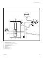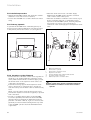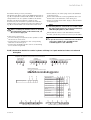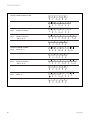
1
Instructions for Installation and Use
uniSTOR
Unvented hot water storage cylinder
GB
VIH GB 125 S
VIH GB 155 S
VIH GB 180 S
VIH GB 210 S
VIH GB 260 S
VIH GB 310 S
Contents
Page
Page
1
Description . . . . . . . . . . . . . . . . . . . . . .
3
6
Commissioning . . . . . . . . . . . . . . . . . . . 20
1.1
1.2
1.3
1.4
1.5
DHW Temperature Control . . . . . . . . . . . . . . . .
CH Control . . . . . . . . . . . . . . . . . . . . . . . . . . . . .
Immersion Heater . . . . . . . . . . . . . . . . . . . . . . .
Applications . . . . . . . . . . . . . . . . . . . . . . . . . . . .
Typical applications . . . . . . . . . . . . . . . . . . . . . .
3
3
3
3
3
6.1
6.2
6.3
6.3.1
6.4
Filling Secondary DHW Circuit . . . . . . . . . . . . . 20
Filling the Primary Circuit . . . . . . . . . . . . . . . . . 20
Operating the Boiler . . . . . . . . . . . . . . . . . . . . . 21
Cylinder Commissioning Checklist . . . . . . . . . . 21
User’s Instructions . . . . . . . . . . . . . . . . . . . . . . . 21
2
Technical data . . . . . . . . . . . . . . . . . . .
4
7
Maintenance . . . . . . . . . . . . . . . . . . . . . 21
3
Instructions for use . . . . . . . . . . . . . . .
6
8
Fault finding . . . . . . . . . . . . . . . . . . . . . 22
3.1
3.2
3.3
3.4
3.5
3.6
Introduction . . . . . . . . . . . . . . . . . . . . . . . . . . . .
Liability . . . . . . . . . . . . . . . . . . . . . . . . . . . . . . . .
How to use your uniSTOR hot water cylinder .
Immersion heater . . . . . . . . . . . . . . . . . . . . . . . .
Important notes . . . . . . . . . . . . . . . . . . . . . . . . .
Guarantee . . . . . . . . . . . . . . . . . . . . . . . . . . . . . .
6
6
6
7
7
7
4
Note To Installers . . . . . . . . . . . . . . . . .
8
4.1
4.2
Secondary System . . . . . . . . . . . . . . . . . . . . . . .
Secondary Return . . . . . . . . . . . . . . . . . . . . . . .
8
8
5
Installation . . . . . . . . . . . . . . . . . . . . . .
9
5.1
Installation requirements . . . . . . . . . . . . . . . . .
5.1.1 Siting . . . . . . . . . . . . . . . . . . . . . . . . . . . . . . . . . .
5.1.2 Mains Water Pressure . . . . . . . . . . . . . . . . . . . .
5.1.3 Pipework – Primary Circuit . . . . . . . . . . . . . . . .
5.1.4 Discharge Pipework . . . . . . . . . . . . . . . . . . . . . .
5.1.4.1 High Level Termination . . . . . . . . . . . . . . . . . . .
5.2
Dimensions . . . . . . . . . . . . . . . . . . . . . . . . . . . . .
5.3
Functional diagrams . . . . . . . . . . . . . . . . . . . . .
5.4
Installation procedure . . . . . . . . . . . . . . . . . . . .
5.4.1 Primary pipework . . . . . . . . . . . . . . . . . . . . . . . .
5.4.2 Secondary system Pipework . . . . . . . . . . . . . . .
5.4.3 Safety valve discharge pipework . . . . . . . . . . .
5.4.4 Drain Valve . . . . . . . . . . . . . . . . . . . . . . . . . . . . .
5.4.5 Electrical Connections and Controls . . . . . . . .
5.4.5.1 Immersion Heater . . . . . . . . . . . . . . . . . . . . . .
5.4.5.2 Electrical Connections to Cylinder Controls .
5.4.5.3 Connection details for control systems
utilising 2 x 2 port motorised valves via
external wiring box . . . . . . . . . . . . . . . . . . . . . .
5.4.5.4 Connection details for connection to
any UK standard boiler . . . . . . . . . . . . . . . . . .
9
9
9
9
9
10
11
12
14
14
14
15
15
16
16
16
Appendix
Benchmark Cylinder Commissioning
Checklist . . . . . . . . . . . . . . . . . . . . . . . . . . . . . . . 26
17
19
We cannot accept responsibility for any damage
which may occur as a result of non-observance of
these instructions.
Subject to alteration.
2
uniSTOR GB
Description 1
1 Description
The uniSTOR range of unvented hot water storage
cylinders are indirectly heated cylinders which are
designed for use with UK standard boilers in hot water
supply systems.
uniSTOR cylinders are available in six sizes; 125, 155, 180,
210, 260 and 310 litre. The cylinders are of stainless
steel construction, insulated with EPS and enclosed in a
decorative casing. They are supplied with all necessary
cold and hot water controls and a 2 port valve for
control of domestic hot water.
The uniSTOR cylinders operate using a mains water
pressure supply and do not require a feed from a cold
water storage tank. The uniSTOR cylinders have 22 mm
DHW outlet and cold water mains inlet connections for
optimum flow rate. To achieve optimum performance
from the uniSTOR an adequate cold water mains supply
pressure and flow rate must be available (see section
4.1.2: Mains Water pressure).
1.1 DHW Temperature Control
The uniSTOR is supplied fitted with a user adjustable
domestic hot water (DHW) thermostat which controls a
2 port motorised valve and hence the temprature of the
water in the uniSTOR.
1.4 Applications
The Vaillant uniSTOR can be connected to any UK
standard boiler.
1.5 Typical applications
– Single bathroom property:
uniSTOR 125
– Single bathroom property with an en-suite shower
room:
uniSTOR 125 / 155
– Two bathroom property:
uniSTOR 155 / 180
– Two bathroom property with an en-suite shower room:
uniSTOR 180 / 210
– Larger properties:
uniSTOR 260 / 310
Commercial use:
Size depending upon hot water requirements
Note:
1 Select the appropriate boiler to match the
heating load (with the normal allowance for
heating up from cold) plus an allowance for
heating the hot water cylinder. Typically it is
practice to allow an additional 2-3 kW for the
hot water production.
2 Consideration should be given to the use of a
larger size of cylinder than shown above
where high water demands are likely.
1.2 CH Control
Central heating is controlled by a separatly fitted 2 port
valve in conjunction with suitable external controls, such
as a programmer, room thermostat or thermostatic
radiator valves. The external electrical controls should
be wired to the 2 port valve and cylinder thermostat in
the normal way, as shown in the section Electrical
Connections and Controls.
1.3 Immersion Heater
uniSTOR cylinders are also provided with an auxiliary
back up 3 kW electric immersion heater, including
operating thermostat and energy cut out.
The immersion heater is fitted behind the front panel.
It is designed for use in unvented installations and
contains a safety overheat thermostat in addition to the
operating thermostat.
For the uniSTOR 260 and 310 an additional second
immersion heater will be available as an accessory.
Note:
Only the correct immersion heater containing a
safety overheat thermostat may be used for
replacement.
uniSTOR GB
3
2 Technical data
2 Technical data
Size
VIH GB 125 S VIH GB 155 S VIH GB 180 S VIH GB 210 S VIH GB 260 S VIH GB 310 S
Unit
125
litres
155
180
210
260
310
Maximum water supply pressure
10
bar
Operating pressure
3.5
bar
Pressure reducing valve
3.5
bar
Expansion relief valve
6.0
bar
Expansion vessel charge pressure
4.0
bar
T/P valve
95 / 7.0
°C/bar
Net weight
28
30
33
39
44
49
kg
Weight (full)
145
175
205
245
310
340
kg
Height
969
1179
1339
1499
1789
2109
mm
Cylinder connections:
Cold mains inlet
22 mm compression
DHW outlet
22 mm compression
Balanced pressure cold water outlet
22 mm compression
Secondary return
G 3/4
Primary flow
22 mm compression
(on 2 port valve)
Primary return
22 mm compression
Electrical connections:
3 kW Immersion heater
(according ENBS 60335)
230/240 V, 50 Hz
Length of Immersion heater
430
Three port valve
230/240 V, 50 Hz
Cylinder thermostat
230/240 V, 50 Hz
mm
Coil Specifications:
Heat loss
1.4
1.7
1.8
1.9
2.1
2.4
kW/24h
Heat up time
21
23
24
27
35
47
min
Recovery
18
18.5
19
22
30
42
min
Note:
Heat up time based on a primary flow rate of
15 l/min at 80 °C.
Temperature rise is from 15 °C to 65 °C.
4
uniSTOR GB
VIH GB 310 S
Cylinder Heat Up Times
60
VIH GB 260 S
70
50
VIH GB 210 S
60
40
VIH GB 180 S
50
VIH GB 155 S
30
40
VIH GB 125 S
30
20
20
10
12
15
20
25
30
Reheat time for 70 % of cylinder contents (minutes)
Approximate cylinder heat up time 15 °C to 65 °C (minutes)
Technical data 2
35 38
Heat input to cylinder (kW)
Fig. 1 Cylinder heat up times
uniSTOR GB
5
3 Instructions for use
3 Instructions for use
3.1 Introduction
Your Vaillant uniSTOR unvented hot water cylinder and
Vaillant boiler, together provide you with a modern,
efficient, high performance heating and hot water
system.
Because your uniSTOR hot water cylinder is supplied
with water directly from the mains, you get the benefit
of mains pressure hot water at your hot taps, without
the need for storage tanks in the loft and without a hot
water pump. The uniSTOR is made from high quality
stainless steel within an easy clean casing. The cylinder
is fully insulated using environmental friendly EPS
insulation to help keep your hot water running costs at a
minimum, and protect the environment!
Note!
Your uniSTOR unvented hot water cylinder must
be installed by a competent person in
accordance with current Building Regulations.
Do not remove or adjust any component part of
this cylinder. In the unlikely event that your
uniSTOR develops a fault, such as a flow of hot
water from the discharge pipe, switch the boiler
and immersion heater off and contact Vaillant
Ltd or your installer.
Note!
If the uniSTOR is installed in a cupboard used
for airing purposes please ensure that clothing
or other articles are not placed on the cylinder
or its associated controls.
Your uniSTOR cylinder is tailor made to accompany a
Vaillant boiler as well as any other UK standard boiler.
All Vaillant boilers are equipped with 'built-in' energy
saving technology, such as burner modulation, anti
cycling control and high efficiency heat exchangers.
Note!
Access should always be maintained to allow
operation of the domestic hot water thermostat
control.
Please read these instructions carefully to ensure that
you get the very best out of your Vaillant heating and
hot water system.
3.3 How to use your uniSTOR hot water cylinder
3.2 Liability
Check that the boiler is operational as detailed in the
instructions for use supplied with the boiler.
Warning!
We can accept no liability whatsoever for damage or
injury resulting from failure to observe these
instructions.
Specified use
Vaillant uniSTOR unvented cylinders are made to fulfil
the latest technical specification and official safety
regulations. These cylinders are designed for use with
UK standard boilers for use in hot water supply systems.
The term 'specified use' also covers observance of the
operating and installation instructions, along with
adherence to the servicing schedules. At the rear of this
manual you will find a Benchmark Cylinder Commissioning
Checklist which should be completed by the installer
and/or commissioning engineer and handed to the user.
All CORGI registered installers carry a CORGI ID card and
have a registration number. Both should be recorded in
your Cylinder Commissioning Checklist. You can check
your installer by calling CORGI direct on 01256 372300.
6
Your boiler and uniSTOR unvented hot water cylinder
will provide both central heating and mains pressure hot
water.
The domestic hot water thermostat on the uniSTOR can
be set from 20 °C to 65 °C. The desired temprature will
be set by the installer while commissioning the uniSTOR
(normally a setting of 60 °C is adequate).
Note!
In hard water areas the DHW temperature
selected should not exceed this setting to avoid
possible scale build-up.
If a programmer has been fitted to control the central
heating and hot water, check that this is set to the
desired on and off periods.
The boiler will then operate automatically to heat the
cylinder contents at the desired times to the
temperature selected. When domestic hot water is used,
the boiler will operate to re-heat the cylinder as
required.
uniSTOR GB
Instructions for use 3
3.4 Immersion heater
3.5 Important notes
The electric immersion heater behind the front panel is
provided as a back up means of water heating and is not
intended for use at the same time that the boiler is
heating the cylinder.
Shutting down the uniSTOR cylinder
To shut down the heating and hot water system for
short periods, simply turn off the boiler as shown in the
instructions supplied with the boiler.
Frost protection
Please ensure that if you are absent during a period of
frost the central heating system remains in operation
and the rooms and uniSTOR cylinder are kept above
freezing point.
3
Alternatively you can drain the central heating system,
boiler and uniSTOR cylinder. Please contact your
Installer.
Care and Maintenance
ON/OFF
2
The casing of the uniSTOR cylinder may be cleaned with
a damp cloth and a little soap. Do not use any abrasive
or solvent material which could damage the case or
fittings.
It is important that your hot water cylinder is serviced
annually by a competent person. Please contact your
installer or Group Service (0870 - 6060777) for further
details.
1
3.6 Guarantee
Fig. 1a
1
2
3
Immersion heater
Switch (Immersion heater ON/OFF)
Additional immersion heater for uniSTOR 260 and 310
(as accessory)
Vaillant offers a guarantee of 25 years for the stainless
steel vessel against faulty materials or maufacture.
The following information is important as without it your
guarantee may be invalid.
1. The warranty will become invalid if the damage is
due to frost damage, transient voltages, lightning
strikes or any act of vandalism or mis use
2. The proof of purchase must be produced in the event
of any warranty claim (bill of sale)
3. The uniSTOR must be installed by a competent
person to the prevailing standards, installation book
and building regulations at the time of installation
4. The Benchmark Cylinder Commissioning Checklist
must be completed on installation and kept up to
date
5. The uniSTOR must be serviced annually
6. The installation must be in an appropriate location
and its use is restricted to potable water (chloride
levels less than 200 mg/l)
7. Tampering or modification will invalidate the
warranty
8. The guarantee card must be completed and returned
to Vaillant Ltd. within 30 days of purchase
9. This guarantee does not cover the effects of scale.
For all other Vaillant parts (electrical, thermal controls,
valves and design elements) Vaillant carry a 2 year
guarantee.
uniSTOR GB
7
4 Note To Installers
4 Note To Installers
This product has been assessed and found to comply
with the requirements of the Building Regulations for
unvented hot water storage systems and must not be
altered or modified in any way.
The installation must be carried out by a competent
person and be in accordance with the relevant
requirements of the Local Authority, Building
Regulations, Building Regulations (Scotland), Building
Regulations (Northern Ireland), and the bye-laws of the
local Water Undertaking. The installation is subject to
Building Regulation approval, notify the Local Authority
of intention to install. In the event of parts replacement,
use only genuine spare parts supplied by Vaillant Ltd.
4.1 Secondary System
Accessories:
- Additional immersion heater 3 kW
- VR 65 Control Center for new
Vaillant boilers
No. 0020006765
No. 307 215
Prior to installation, ensure that the cylinder is stored
upright in dry conditions. The uniSTOR must be kept
upright during transportation.
Please also refer to “General Requirements“ in the
installation instructions supplied with the boiler.
4.2 Secondary Return
A scondary return connection is provided in the water
control pack.
Connect onto the 1/2“ pipe on the control group using a
WRAS approved circulation pump which incorporates a
check valve to prevent backflow (see fig. 6).
The uniSTOR is provided with all necessary safety and
control devices for unvented DHW operation.
These are as follows:
A A prefitted temperature and pressure relief valve
(95 °C, 7 bar).
B A Thermal cut set at 90 °C which when wired to the
2 port valve will isolate the heat source in the event
of failure of the cylinder thermostat.
C A cylinder thermostat (20 °C - 60 °C)
D Expansion relief valve (6.0 bar) incorporating a non
return valve.
E Pressure limiting valve (3.5 bar) incorporating a line
strainer.
Check that the cylinder has been supplied with the
following:
– Packed inside cylinder carton
- Water control pack (pressure reducing valve,
expansion relief valve; connections for: balanced cold
water, secondary return, expansion vessel)
- Motorised 2 port valve
- Tundish
- Cylinder drain valve,
- Installation and user instructions,
- Mounting kit for expansion vessel.
Expansion vessel:
- 12 litre for VIH GB 125/155
(max. storage volume by 3,5 bar = 155 l)
- 18 litre for VIH GB 180/210
(max. storage volume by 3,5 bar = 255 l)
- 25 litre for VIH GB 260/300
(max. storage volume by 3,5 bar = 315 l)
8
uniSTOR GB
Installation 5
5 Installation
5.1 Installation requirements
In order to minimise frictional losses minimum 22 mm
bore is recommended for new cold mains supply
pipework into the dwelling although satisfactory
performance can be achieved with 15 mm bore pipework.
5.1.1 Siting
Locate the uniSTOR in the building in the most
convenient position ensuring that:
– The discharge pipe from the tundish can be installed
with a minimum fall of 1:200 and must be terminated
in a safe and visible position (see section 4.1.4
Discharge pipework).
– The base chosen for the unit is level and capable of
supporting the weight of the cylinder when full
(see section 8: Technical Data).
– The installation site is frost-free. If necessary provide
a frost protection thermostat.
– Access is available for user operation of the DHW
temperature control under the front panel.
– Suitable clearances exist to allow installation, checking
and repressurising of the expansion vessel.
– The installation site chosen does not result in
excessive ”dead leg” distances, particularly to the
point of most frequent use.
– A suitable cold mains water supply pipe can be
provided to the uniSTOR direct from the main water
stop valve of the building.
5.1.2 Mains Water Pressure
The DHW performance of an unvented cylinder
installation will correspond to the available mains water
supply pressure and flow rate. To achieve optimum
performance from the uniSTOR a suitable cold mains
water supply must be available, i. e. the measured static
pressure from the incoming mains water supply should
be at least 2.0 bar. A corresponding flow rate at least
20-25 l/min should be available.
Note:
Mains water pressures will reduce during periods
of peak demand. Ensure that measurements are
taken during these periods.
Example:
If the measured cold mains supply pressure is 2 bar
static and the cold mains flow rate available is 30 l/min,
the available flow rate of mixed water at 40 °C will be
25 l/min (from 15 l/min hot water from the uniSTOR at
60 °C together with 10 l/min cold water at 10°C).
The uniSTOR will operate satisfactorily with water
supply pressures below 2 bar although flow rates will be
reduced. If the supply pressure is below 1 bar the
uniSTOR unvented storage cylinder should not be
installed. Contact Vaillant Ltd. for details on alternative
hot water supply systems.
uniSTOR GB
5.1.3 Pipework – Primary Circuit
The primary circuit pipework between the Vaillant boiler
and the uniSTOR should be installed using copper tube
of minimum size 22 mm.
If the distance between the boiler and the cylinder is
excessive, a larger pipe diameter may be necessary. It is
not necessary to install a circulating pump in this
pipework because all Vaillant wall mounted boilers
contain a built-in circulating pump (except ecoMAX pro
open-vented boilers).
If the uniSTOR cylinder will be used with any other UK
Standard boiler a suitable pump must be fitted into the
primary circuit.
5.1.4 Discharge Pipework
The outlet connections of both the temperature and
pressure relief valve and expansion relief valve should be
connected in 15 mm copper tube to the tundish supplied.
The tundish should be installed vertically, as close to the
uniSTOR as possible and within 500 mm of the
temperature and pressure relief outlet. It must be
positioned away from any electrical components and
installed in the same space as the uniSTOR cylinder, so
that it is visible to the user.
The D1 discharge pipe from the T&P Valve/Expansion
valve can be teed together upstream of the tundish (see
fig 6). The discharge pipework must be installed using
minimum 22 mm copper pipework from the 22 mm
connection on the tundish to a safe and visible discharge
point. There must be a vertical section of pipe at least
300 mm long, below the tundish before any bends or
elbows in the pipework. Increase the diameter of the
pipework if the total resistance of the discharge
pipework exceeds the figures shown in the table below.
The installation of the discharge pipework must be in
accordance with G3 (see fig. 2).
Minimum size
of discharge
pipework
from Tundish
Maximum total resistance Resistance created
allowed expressed as a
by each elbow
length of straight pipe
or bend
(i. e. no elbows or bends)
22 mm
up to 9 m
0.8 m
28 mm
up to 18 mm
1.0 m
35 mm
up to 27 mm
1.4 m
9
5 Installation
Example
22 mm discharge pipe having 4 elbows and a length of
7 m from the tundish to the discharge point:
Resistance for 4 elbows
at 0.8 m each
= 3.2 m
Resistance of discharge pipe = 7.0 m
Total Resistance
= 10.2 m
The total resistance of the discharge pipework is
greater than the maximum allowed for 22 mm
pipework (9 m). Therefore calculate the next largest
size.
providing that where children may play or otherwise
come into contact with discharges a wire cage or similar
guard is positioned to prevent contact, whilst
maintaining visibility.
Do not fit any valves or taps to the discharge pipework.
Ensure the pipework has at least 1:200 fall continuously
from the tundish to the discharge point.
The discharge pipe from the pressure relief valve of the
Vaillant boiler may be teed-into the discharge pipework
from the uniSTOR downstream of the tundish in the
horizontal pipework.
5.1.4.1 High Level Termination
28 mm discharge pipe with 4 elbows and 7 m length
from tundish to discharge point.
Resistance for 4 elbows
at 1.0 m each
= 4.0 m
Resistance of discharge pipe = 7.0 m
Total Resistance
= 11.0 m
The total resistance of the discharge pipework is less
than the maximum allowed for 28 mm pipework
(18 m) therefore the discharge pipework size is
acceptable.
metal discharge pipe from
temperature relief valve to tundish
safety
device
(e.g.
temperature
relief valve)
500 mm
maximum
tundish
Discharge below
fixed grating
300 mm
minimum
Providing that the point of termination is such that
persons in or around the building will not be endangered
should discharge take place, the method of termination
shown in fig. 8a is satisfactory. Examples of points to
consider when deciding whether a location for the high
level discharge is suitable are:
– The possibility, taking into account wind effect, that
someone may be in the path of the water being
discharged and if so, whether the temperature of the
discharge water will have been sufficiently reduced to
not be dangerous. Thermal conductivity of the
structure’s surface, climatic conditions and location
and orientation of the discharge pipe may or may not
have an effect on reducing the temperature of the
discharge water.
– The location of windows and similar openings.
– The likelihood of a pram being left beneath the point
of discharge.
– The ability of the structures surface to withstand near
boiling water.
– The possibility of ice formation if water is discharged
onto pedestrian walkways.
metal discharge pipe from tundish
with continuous fall. See 7.5
Table 4 and worked example
fixed grating
tundish
trapped gully
300 mm
minimum
discharge pipe
Fig. 2 Typical discharge pipe arrangement
Under fault conditions, the discharge warning pipe can
emit water at near boiling temperature. Ensure the
discharge pipe terminates at a safe position where there
is no risk of contact with hot water by persons in or
about the building (save and visible).
A suitable position for the discharge point is ideally
below a fixed grating and above the water seal in a
trapped gully. Downward discharges at low level, i. e. up
to 100 mm above external surfaces such as car parks,
hard standings, grassed areas, etc. are acceptable
10
X = diameter of
discharge pipe
X
Fig. 3 High level termination
uniSTOR GB
Installation 5
5.2 Dimensions
1
7
h
a
b
2
g
3
4
5
1
2
3
4
5
6
7
598
554
e
d
c
f
6
45°
DHW outlet
Temperature and pressure relief valve
Immersion heater
Primary flow
Cold water mains inlet
Primary return
Additional immersion heater
(for uniSTOR 260 and 310; as accessory)
Fig. 4 (all dimensions in mm)
a
b
c
d
e
f
g
h
VIH GB 125 S
938
969
421
351
281
556
728
–
VIH GB 155 S
1148
1179
454
384
314
589
903
–
VIH GB 180 S
1308
1339
454
384
314
589
1038
–
VIH GB 210 S
1468
1499
454
384
314
589
1118
–
VIH GB 260 S
1758
1789
454
384
314
589
1408
1376
VIH GB 310 S
2078
2109
454
384
314
589
1648
1376
uniSTOR GB
11
5 Installation
5.3 Functional diagrams
DHW
2
4
M
3
1
A
B
M
5
Fig. 5
1
2
3
4
5
Boiler
uniSTOR cylinder
2 port motorised valve (provided with the boiler)
Immersion heater
2 port motorised valve
A
B
Boiler flow
Boiler return
12
uniSTOR GB
Installation 5
10
7
5
4
6
1
3
2
8
9
Fig. 6
1
2
3
4
5
6
7
8
9
10
Temperature and pressure relief valve
Expansion relief valve
Pressure limiting valve combined with strainer
Secondary return connection
Balanced pressure cold water outlet
Cold water mains inlet
DHW outlet
Tundish
Cylinder drain point
Expansion vessel
uniSTOR GB
13
5 Installation
5.4 Installation procedure
• Unpack the uniSTOR cylinder and check the contents
•
(detailed in section 4: notes to installers).
Position the uniSTOR in accordance with section 5.1.1:
Siting
• Install the drain valve in the cold mains supply
•
5.4.1 Primary pipework
To prevent the uniSTOR from overheating the 2 port
motorised valve supplied with the boiler must be fitted
to the primary flow to the indirect coil (see figure 5).
between the uniSTOR cylinder and the cold water
control valves at the lowest point.
Install the assembled cold water control valves (fig. 8)
in the cold mains supply at a convenient position
adjacent to the uniSTOR cylinder, ensuring adequate
space exists for service access and allow for
connection of the discharge pipe from expansion relief
valve.
3
A
5
4
1
B
´B´ Port
´A´ Port
A
2
B
Fig. 8
Fig. 7
5.4.2 Secondary system Pipework
• Connect the two cold water control valves together as
•
•
•
shown in fig. 8, ensuring that the orientation of the
valves, when installed in the cold mains supply, allows
the 15 mm outlet of the expansion relief valve to be
connected to the tundish.
Install the discharge pipe from the expansion relief
valve so that it has a contimous fall to outside in a
safe and visible position where it will be unaffected by
frost.
Never close the outlet of the expansion relief valve.
Activate the expansion relief valve regularly to prevent
from calcination.
Provide a cold water mains supply to the uniSTOR.
To ensure optimum performance from the uniSTOR,
and particularly in installations where the balanced
pressure cold water outlet (5, fig. 8) is to be used, the
pipework provided from the building mains stop valve
to the uniSTOR cylinder should be minimum 22 mm
copper tube.
14
A
B
1
2
3
4
5
Mains Cold water inlet
Connection to cylinder
Connection to expansion vessel
Expansion relief valve
Pressure limiting valve combined with strainer
Secondary return connection
Balanced pressure cold water outlet
Important
No isolate valve shall be installed between the
assembled cold water control valves and the
cylinder.
uniSTOR GB
Installation 5
The Vaillant uniSTOR is provided with an external
expansion vessel.
• Connect the expansion vessel to the installed water
controls by either:
i. Screwing the vessel directly into the control assembly at the purpose provided connection (1, fig. 8) or,
ii. Connecting the vessel to the control assembly via
copper pipe or a suitable approved flexible connection hose, ensuring that the vessel is adequately
supported.
Use the supplied Expansion Vessel Mounting Kit for
wall installation.
5.4.4 Drain Valve
The drain valve supplied with the uniSTOR has to be
fitted in the cold water mains supply between the
uniSTOR cylinder and the cold water control valves as
low as possible (see fig. 6)
We recommand to fit a hose pipe in the outlet of the
drain valve approximately 1 meter below the bottom of
the cylinder (this can be achieved by connecting a
suction hose to the outlet of the drain valve).
Flow rates from uniSTOR, hot 60 °C.
• Connect the balanced pressure cold water supply (if
required) to the cold water control pack (see fig. 8).
8 bar*
Note:
In areas where the mains water pressure is high
(4 bar or above) the cold water supply to a bath
or shower mixer valve can be taken from the
balanced pressure cold water outlet (5, fig. 8) of
the cold water controls. This will ensure that
both hot and cold supplies to the mixer valve
are at approximately the same pressure. The
cold water supply for all other terminal fittings
should be teed into the cold water supply
pipework to the uniSTOR upstream of the cold
water controls.
flow out (litres/min) of the system
40
1 bar*
20
10
0
20
30
40
10
flow available (litres/min) at entry to system
5.4.3 Safety valve discharge pipework
•
Connect the temperature/pressure relief and
expansion relief valves to the tundish using 15 mm
pipe and install the discharge pipework from the
tundish in accordance with section 5.1.4: Discharge
Pipework.
Flow rates from uniSTOR, hot cold mixed.
40
flow out (litres/min) of the system
•
3 bar*
2 bar*
30
• Connect the DHW outlet pipework to the 22 mm
domestic hot water outlet on the uniSTOR.
Continue with 22 mm size pipe to the first tee fitting
after which 15 mm pipework should be adequate.
If the pipe runs are of excessive length or there are
several terminal fittings supplied, extend the length of
pipework in 22 mm.
Connect the secondary return if required as shown in
4.2: Secondary Return.
4 bar*
Mixed water @ 40 °C, mixed from
60 % hot water @ 60 °C and
40 % cold water @ 10 °C
8
4
3
2
bar*
bar*
bar*
bar*
1 bar*
30
20
10
0
10
20
30
40
flow available (litres/min) at entry to system
Notes:
1) flow rates shown apply to situations where the supply is capable of supplying an adequate dynamic pressure.
3) where static water pressures are less than 1 bar, consult Vaillant Ltd.
* static supply pressure of incoming water supply.
Fig. 8a
uniSTOR GB
15
5 Installation
5.4.5 Electrical Connections and Controls
Important:
The immersion heater incorporates an energy
cut-off device and must not under any
circumstances be replaced by a standard
immersion heater.
All electrical connections conform to BS.
The position of the discharge pipes (tundish), drain
valves and motorised valves etc. shall be positioned
away from any electrical components.
5.4.5.1 Immersion Heater
The uniSTOR VIH 125 - 310 cylinders are equipped with a
factory fitted immersion heater.
All internal wiring is factory mounted.
Warning:
The immersion heater must be earthed.
Only a correct genuine Vaillant spare part is permitted.
All uniSTOR cylinders with a volume of 260 l or 310 l are
provided with an additional boss to fit a second
immersiom heater. The immersion heater can be ordered
as accessory (No. 0020006765)
5.4.5.2 Electrical Connections to Cylinder
Controls
Install a separate electrical supply to the immersion
heater in accordance with the current IEE wiring
regulations (BS 7671). The immersion heater must be
wired in 3 x 2.5 mm2 heat-resisting cable from a double
pole isolating switch. The circuit must be protected by a
13 amp fuse. The connection details for the immersion
heater are shown in fig. 9.
To Wiring box:
1
7
2 10
3
230 V AC
3 kW
2
N
1
L
N
2
L
1
b
1
2
a
1
3
2
3
2
1
Fig. 10 Electrical Connections to Cylinder Controls
3
Fig. 9 Immersion heater electrical connections
a Cylinder Controls
b Immersion heater
16
1 Thermostat (adjustable)
2 Thermal cut out (with Reset button)
3 Sensor
Warning:
The uniSTOR cylinder must be eartherd.
The Vaillant uniSTOR and accompanying Vaillant boiler
may be controlled using various programmers and room
thermostats, details of which are given in section:
Control Options.
The uniSTOR cylinder has a prefitted cylinder thermal
cut out and thermostat.
uniSTOR GB
Installation 5
• Connect the 2 port valve flying lead to the terminals
All internal wiring is factory mounted.
The thermostat which controls the DHW temperature (1,
fig. 10) is adjustable between 20 and 65 °C. The built in
safety thermal cut out operates at 90 °C. Should the
thermal cut out be brought into operation, the
motorized 2 port valve will be operated and shut the
primary flow to the cylinder. Press the reset button (2,
fig. 10) to reset thermal cut out and motorised valve.
of the wiring box.
• Connect the terminals of the programmer and room
thermostat to the terminals of the wiring box.
• Connect a 3 amp fused mains supply to the terminals
of the wiring box.
Note:
All wiring must be carried out in accordance with
BS 7671: Requirements for electrical installations
(IEE Wiring Regulations, 16th edition).
Important:
Before resetting the thermal cutout or changing
the temperatur setting of the thermostat, set
the electrical supply off.
• Check that the sensors from the immersion heater
and the cylinder are positioned correctly in the tubes.
Connections to wiring box
• Provide a wiring box adjacent to the cylinder to make
the electrical connections.
• Connect the boiler terminals to the corresponding
terminals of the wiring box.
• Connect the uniSTOR cylinder controls to the wiring
box as shown in figure 10.
Note:
A special accessory is offered for the electrical
connections between the uniSTOR and an
ecoEURO appliance (No. 307 215).
5.4.5.3 Connection details for control systems utilising 2 x 2 port motorised valves via external
wiring box
Diagram only applies to the specific controls mentioned
3 amp fused
main supply
L
N
L
N
ecoTEC
terminal strip
E
Programmer
for programmer connections see fig. 16.d
L
N
3
4
5
N
L
CENTRAL
HEATING
ON
L
N
3
4
5
5
3
6
Room thermostat
5
9
6
Vaillant VRT 9090
E
C
A
3
1
3
L
3
2
HOT
WATER
ON
HOT
WATER
OFF
7
8
External wiring box
(Do not use pre-wired printed circuit board type)
N
N
L
L 3
4
5
6
7
8
9
10
not used
10
7
uniSTOR Cylinder
1
2
E
3
ACL Drayton Digistat 2, 3, 4
E
ACL Drayton RTS 1, 2
N
Danfoss Randall RX-1
EARTH
10
3
4
BLUE
BROWN
GREY
ORANGE
Hot water 2 port motorised valve
C
B
E
4
2
1
Danfoss Randall RET 230
N
3
L
Tower SS
4
2
2
3
1
1
E
Honeywell T6360
Horstmann HRT 1
4
2
1
E
2
1
1
3
E
4
Sunvic TLX 2000 series
5
N
Danfoss Randall RMT 230
Siemens-Landys & Staefa RAD 1
E
L
E
EARTH
E
5
9
3
4
BLUE
BROWN
GREY
ORANGE
Central heating 2 port motorised valve
Fig. 11 Connection details for control systems utilising 2 port motorised valve
uniSTOR GB
17
5 Installation
Lifestyle LP241, LP 522, LP 722
Tempus 6, Tempus 7
Danfoss Randall CP 715, FP715
Note:
*Earth not required
Link L - 2 - 5
Grässlin Towerchron QE2
Honeywell ST699B, ST799A
Note:
Horstmann Channel Plus H21, H27
*Earth not required
Link L - 2 - 5
Siemens-Landis & Staefa RWB2, RWB9
Potterton Myson EP 2002, EP 3002, EP 6002
Note:
1
2
3
4
5
3
not used
6
4
E
N
L
1
2
3
4
5
3
not used
7
6
E
N
L
1
2
3
4
*
5
3
not used
7
6
E
N
L
1
2
3
4
5
*
5
3
7
not used
6
not used
N
L
1
2
3
4
5
3
not used
7
6
L
N
3
4
5
6
7
3
5
6
not used
7
not used
N
L
1
2
3
4
5
3
not used
7
6
E
N
L
1
2
3
4
5
*
5
3
7
not used
6
not used
N
L
1
2
3
4
5
3
not used
7
6
E
N
L
1
2
3
4
5
5
3
not used
7
6
N
L
1
2
3
4
5
3
not used
7
6
6
8
Link L - 5 - 8
Honeywell ST6200, ST6300, ST6400
Note:
L
*Earth not required
Danfoss Randall Set 2E, Set 3E
Note:
N
6
Link L - 5
Sunvic Select 207
Fig. 12 Connection details between programmer and wiring box.
18
uniSTOR GB
Installation 5
5.4.5.4 Connection details for connection to any UK standard boiler
Main Supply
3 Amp Fused
N
Boiler Terminal
8
L
7
6
2 Channel Programmer
5
4
3
2
1
N
L
HW CH HW
OFF OFF ON
CH
ON
N/U N/U
E
1/N 2/L
PL PN PE
E
1/N FS RS 2/L CE
E
1/N 2/L
7
6
PL PN PE
External wiring box
(Do not use pre-wired printed circuit board type)
1
2
N
L
3
4
5
6
7
8
9
L
10
N
Pump
not used
E
1/N
9
2/L RS
6
1/N
9
E
E
1/N 10 2/L
E
7
10
E
N/U
E
BL BR GR OR
Spring Return Zone
Valve
Heating Zone
COM
N SW/L E
Room Thermostat
E
BL BR GR OR
Spring Return Zone
Valve
1
2
3
Cylinder Stat
uniSTOR VIH GB ...
Fig. 13 2 x 2 port valve system
Boiler
L, 1:
RS, 2:
FS, 3:
N, 4:
E, 5:
PE, 6:
PN, 7:
PL, 8:
CE:
BR
BL
GR
OR
W
Terminal Designation:
Mains Live
Room Thermostat
Frost Stat
Mains Neutral
Mains Earth
Pump Earth
Pump Neutral
Pump Live
Chassis Earth
Important:
1-10 must go to the corresponding number in the wiring
box.
Brown
Blue
Grey
Orange
White
DHW Domestic Hot Water
HTG Heating
uniSTOR GB
19
6 Commissioning
6 Commissioning
6.2 Filling the Primary Circuit
6.1 Filling Secondary DHW Circuit
Note:
Do not manually open the temperature and
pressure relief valve or expansion relief valve for
venting purposes (any foreign matter in the
pipework may cause damage to the valve seats).
Note:
Do not use boiler pressure relief valve for
venting purposes.
• The complete primary CH system must be flushed out
• Ensure that the cylinder drain valve (9, fig. 6) is
closed.
• Open all the hot and cold water taps or other terminal
fittings.
• Open the mains water supply to the uniSTOR and
continue filling until water runs freely from the
terminal fittings, ensuring all air pockets are purged.
• Close the terminal fittings and check the system for
leaks. Specially check the connection of the immersion
heater for leaks.
•
•
with both cold and hot water. Fill and vent the central
heating system as detailed in the boiler installation
instructions.
To assist with this operation set the manual override
lever on the 2 port diverter valve (fig. 7) to the
MANUAL position, and lock in this position by pushing
the lever into the valve head.
Completely drain the CH system, then refill and vent.
Reset the lever on the 2 port valve to the ”AUTO”
position by releasing the manual operating lever from
the valve head (pull outwards).
For commissioning purposes and to reduce the time
for the cylinder contents to reach temperature, set the
cylinder hot water thermostat knob (1, fig. 14) to
setting middle position (approx. 40 °C).
The system should now be thoroughly flushed.
• Open hot water taps at opposite ends of the system
and allow water to discharge for at least 5 minutes.
• Close the hot water taps.
1
C˚
2
3
cylinder
control
immersion
heater
L N
C˚
1
Fig. 14 Electrical Connections to Cylinder Controls
• Operate the boiler as in section 6.3 until both the
•
20
cylinder has reached temperature and all radiators in
the system are hot. Then once again drain the
complete CH system to remove residues from the
pipework and refill and vent again as above.
Reset the manual operating lever on the 2 port valve
to the ”AUTO” position once the system has been
refilled and vented.
uniSTOR GB
6 Commissioning
6.3 Operating the Boiler
• Ensure the boiler mains switch is turned on.
• Ensure that the programmer and thermostats are
•
•
•
calling for heat.
Check that the boiler fires and heats the cylinder
contents and the radiators according to the DHW and
room thermostat settings.
Carry out the commissioning and testing procedures
detailed in the installation instructions supplied with
the boiler.
Upon completion of the commissioning procedures,
set the DHW thermostat knob on the uniSTOR to
approx. 60 °C, and set the back up immersion heater
(fig. 9) thermostat to 60 °C.
Maintenance 7
7 Maintenance
The following maintenance work has to be carried out
annually by the competent installer or Vaillant Service
Solutions.
• Inspection of pressure/temperature relief valve and
•
6.3.1 Benchmark Cylinder Commissioning
Checklist
Complete the Benchmark Cylinder Commissioning
Checklist included in the instructions.
6.4 User’s Instructions
Hand these instructions for use to the user for retention
and instruct in the safe operation of the boiler and
cylinder. Advise the user of the operation of the cylinder
thermostat and the immersion heater thermostat, and
that normally a setting of max, which gives a stored
water temperature of approximately 60 °C is adequate.
•
expansion relief valve.
Manually operate each valve by twisting the operating
cap, and check if water flows unobstructed via the
tundish to the discharge point. Ensure that both valves
re-seat satisfactorily.
Check pressure of expansion vessel.
Turn off mains water supply and open nearest hot
water tap to depressurise the secondary water system.
Check the expansion vessel charge with a pressure
gauge at the test point. If the pressure is below
3.0 bar, top up with suitable air pressure pump.
Complete service section of Cylinder Commissioning
Checklist.
Note:
In the event that parts require replacement, use
only genuine spare parts supplied by Vaillant
Ltd.
Note:
In hard water areas the DHW temperature
setting should not exceed this setting to avoid
possible scale build-up.
Advise the user of the precautions necessary to prevent
damage to the system and to the building if the system
does not remain operative during frost conditions.
Advise the user that the immersion heater is provided
as a back up means of water heating and is not intended
for use at the same time that the boiler is heating the
cylinder.
Finally, advise the user that for continued efficient and
safe operation, the boiler and uniSTOR cylinder should
be serviced at least once a year by a qualified servicing
company. It is important and strongly recommended
that arrangements are made for a maintenance
agreement with a qualified servicing company to ensure
regular servicing of the boiler and cylinder.
Please contact Group Service
(0870 - 6060777) for further details.
Note:
Leave installation, servicing and user
instructions with the user.
uniSTOR GB
21
8 Fault finding
8 Fault finding
Note:
Only genuine spare parts supplied by Vaillant
Limited must be used.
Fault A:
The water from the cylinder is cold.
Does boiler operate?
NO
Do external controls
function?
YES
Remedy fault
according to boiler
instructions.
NO
Remedy fault
according to controls
instructions.
YES
Is 2-port valve in
correct position?
(DHW position).
NO
YES
Does cylinder
thermostat operate?
NO
Replace cylinder
thermostat.
YES
Check/reset
Thermal cut out
Vent heating coil of
air (H, fig. 4).
NO
Check/replace
2-port valve.
Is operation now
OK?
YES
Fault remedied.
Fig. 15
22
uniSTOR GB
Fault finding 8
Fault B:
Water discharging from expansion
relief valve.
Manually reset / seat expansion relief
valve. Is discharge still occuring?
NO
YES
Is the discharge occuring only when the
cylinder is being heated?
NO
YES
Check pressure charge NOT OK
in expansion vessel
Reset pressure in
expansion vessel
Does pressure hold?
YES
OK
Exchange expansion
relief valve.
NO Turn off boiler and
immersion heater. Is
discharge still occuring?
YES
NO
Is pressure downstream
YES of pressure limiting valve
less than 3.0 bar?
NO
Exchange pressure
limiting valve.
Exchange
expansion vessel.
Is operation now
OK?
YES
NO
Fault remedied.
Fig. 16
uniSTOR GB
23
8 Fault finding
Fault C:
Water discharging from temperature/
pressure relief valve (TPRV).
Manually reset the TPRV. Is
discharge still occuring?
NO
YES
YES Check temperature control
of boiler.
Is discharge occuring only
when the boiler is in use?
OK
NO
Is discharge occuring only
when the immersion heater
is in use?
Does 2-port valve change to
heating position when
cylinder reaches
temperature?
YES
NO
Check operation of
cylinder thermostat and
thermal cut out
YES
Replace TPRV.
YES
NO
Are immersion heater
thermostat and cut out
faulty?
NO
NOT Remedy fault
OK according to boiler
instructions.
Reset thermal cut out/
NOT Replace cylinder
OK thermostat.
OK
Replace immersion heater.
Check operation of NOT Replace
2-port valve.
OK 2-port valve.
OK
NO
Is discharge still occuring?
YES
NOT OK
Is operation now OK?
Replace TRPV.
OK
Fault remedied.
Fig. 17
24
uniSTOR GB
Fault finding 8
Fault D:
Deteriorating water pressure and flow
from hot water terminal fittings.
Check incoming main water pressure.
Poor
Inform customer to have water service
checked by water undertaker.
Dirty
Clean / replace strainer.
Faulty
Replace faulty valve.
OK
Check line strainer
(in pressure limiting valve).
OK
Check pressure limiting valve.
OK
Check sytem for blockage.
Blocked
Replace / clear blocked components.
OK
Symptoms still persisting?
YES
NO
Check system as for discharge from
temperature or expansion relief valve.
Fault remedied.
Fig. 18
uniSTOR GB
25
00 2000 5468_00GB 03 2005 • Subject to alteration • Printed in Germany
Head Office: Vaillant Ltd.
Vaillant House
Medway City Estate
Trident Close
Rochester
Kent ME2 4EZ
Service Solutions 0870 6060 777 Technical Advice 01634 292392