1
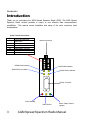
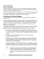
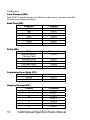
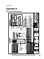
AGM Electronics, Inc – Spread Spectrum Radio, Series ( ) 5017-1
Manual Rev 2
User Manual
Spread Spectrum Radio Modem
1
AGM Spread Spectrum Radio Manual
CONTENTS
INTRODUCTION............................................................................................................................................................3
Overview ..................................................................................................................................................................4
Theory of Operation and Construction...............................................................................................................4
General Specifications ..........................................................................................................................................5
HARDWARE INSTALLATION .....................................................................................................................................6
ANTENNA CONNECTION.........................................................................................................................................6
Short range antenna (Under 1500 feet)...............................................................................................................6
Long range external antenna................................................................................................................................6
POWER CONNECTION.............................................................................................................................................7
CONNECTING TO A PERSONAL COMPUTER.....................................................................................................7
CONNECTING TO RS485 DEVICES........................................................................................................................8
CONNECTING TO AGM DATA HANDLER (DH) RS232 .......................................................................................8
CONNECTING TO AGM INTEGRATED CONTROL STATION (ICS)...................................................................9
CONNECTING TO AGM UNIVERSAL WEB STATION (UWS).............................................................................9
RS-232 connection .................................................................................................................................................9
RS-485 connection .................................................................................................................................................9
CONNECTING TO A 3RD PARTY PLC...................................................................................................................10
GETTING STARTED...................................................................................................................................................11
TESTING YOUR INSTALLATION ..........................................................................................................................11
CONFIGURATION.......................................................................................................................................................12
ENTERING COMMAND MODE ..............................................................................................................................12
EXIT COMMAND MODE (CN).................................................................................................................................12
SAVE CHANGES (WR)............................................................................................................................................13
BAUD RATE (BD) ....................................................................................................................................................13
PARITY (NB).............................................................................................................................................................13
COMMUNICATIONS MODE (CS)...........................................................................................................................13
HOPPING CHANNEL (HP)......................................................................................................................................13
SSR’S AS REPEATERS.............................................................................................................................................14
STORE AND FORWARD ........................................................................................................................................14
STREAMING .............................................................................................................................................................14
APPLICATION SPECIFIC........................................................................................................................................15
TECHNICAL SUPPORT .............................................................................................................................................16
DIAGNOSTICS AND TROUBLE SHOOTING ..........................................................................................................17
INDICATOR LIGHTS................................................................................................................................................17
DIAGNOSTIC INDICATOR LIGHTS 2 AND 4 .......................................................................................................17
DIAGNOSTIC / CONFIGURATION JUMPER........................................................................................................18
APPENDIX A................................................................................................................................................................19
FCC COMPLIANCE INFORMATION......................................................................................................................19
APPENDIX B................................................................................................................................................................20
WIRING AND SIMPLIFIED DIAGRAM...................................................................................................................20
AGM Spread Spectrum Radio Manual
2
Introduction
Introduction
Thank you for purchasing the AGM Spread Spectrum Radio (SSR). The AGM Spread
Spectrum Radio modem provides a variety of cost effective data communications
possibilities. This manual covers installation and setup of the more commonly used
configurations.
Screw Terminal Connections
Pin
1
2
3
4
5,6
7,8
9,10
Description
Configuration/Diagnostic
Mode Select
Power (-)
Enable 3 Wire RS232
Power (+)
RS485 Shield / Common
RS485 (-)
RS485 (+)
Antenna Connection
1
2
3
4
5
6
RS485 Mode Indicator
8
10
7
RS232 Mode Indicator
9
RS485 Receive Indicator
4
2
X
R
RS232 Connector
.
F
RR
RS232 Receive Indicator
P/X
Failure Indicator
Radio Receive
3
Power / Radio Transmit
Indicator
AGM Spread Spectrum Radio Manual
Introduction
Overview
The AGM AUX/DIN 5017-1 SSR is a low cost radio modem using spread spectrum
technology, operating in the 900 MHz band. The SSR complies with FCC Part 15 rules and
may be operated without licensing. The SSR is intended for short range line of sight
communications of up to 20 miles using external high gain antenna.
The SSR may be wired either for a RS485 or RS232 system. When used with RS485 the
SSR will automatically switch to RS232 for configuration. Either full RS232 or 3 wire RS232
may be used.
The standard SSR communicates over the air waves at 9600 bps. 19200 and 1200 bps are
available on special order.
Default communications is set for 9600 bps, 8 data bits, no parity and 1 stop bit. The SSR
may also be configured for 1200, 2400, 4800, 19200, 38400, or 57600 bps. 7 bit and 8 bit
parity options are also available through configuration.
Theory of Operation and Construction
The heart of the SSR is an industrial hardened radio modem that groups received characters
into packets, adds error checking, and then transmits the packet using spread spectrum
frequency hopping algorithms. Other SSR receive the transmitted packet, checks the packet
for errors and then if no errors sends the received characters to the connected device. The
use of spread spectrum frequency hopping algorithms allows multiple radios to share the
same frequency band with minimal interference.
The SSR may be used with any protocol that uses 7 or 8 bit asynchronous data. This
includes but is not limited to: ASCII Modbus, RTU Modbus, DF1, or DNP3. You do not need
to own AGM Electronics Inc. equipment to use the SSR.
The SSR is configured by using a computer and any terminal emulation software such as
Hyperterminal which is packaged with Microsoft Windows. The SSR may be configured in
the field using a laptop computer and RS232 cable. A RS232 to RS485 adapter is not
required to configure the SSR for RS485 installations.
In most installations, the SSR can be used right out of the box, however AGM Electronics Inc.
will configure your SSR at the factory free of charge.
The hermetically sealed assembly minimizes installation costs.
AGM Spread Spectrum Radio Manual
4
Introduction
General Specifications
Ports – 1 RS232C, 1 RS485
Baud Rate – RS232C/RS485, 1200, 2400, 4800, 9600, 19200, 38400, or 57600 bps
Status Indicators - 7
Operating Temperature Range, -20/80 deg C
Adjustments – Operator configurable locally from a PC
Power – 11/26 vdc +/- 10%, nominal 3 Watts @ 12V.
Physical – 3 X 1.14 X 3.5 (DIN), 3 X 1.14 X 2.7 (AUX)
Frequency – 902 – 928 MHz, Frequency Hopping, Wide band FM modulator.
Network Topology – Peer-Peer, Point- Point, Point- Multipoint, Multi-drop
Channel Capacity – 7 Hop sequences, 25 frequencies
Antenna Connector – Reverse Polarity SMA (Adapter cable to N connector available for
external antennas)
Indoor / Urban range – Up to 1500 feet.
Outdoor with Dipole Antenna range – Up to 7 miles, Line of sight
Outdoor with High Gain Antenna range – Up to 20 miles, Line of sight
Transmit Power – 140 mW
Receive Sensitivity - -110 dBm
FCC Certifications, Part 15.247 – OUR9XSTREAM
Industry Canada (IC) – 4214A-9XSTREAM
5
AGM Spread Spectrum Radio Manual
Hardware Installation
Hardware Installation
The SSR is available pre-configured to your application. When pre-configured, the SSR is
ready for use and you only need to connect your equipment. If not pre-configured or if you
need to modify the configuration you will need to connect the SSR to a computer containing a
RS232 serial port and terminal emulation program. Hyperterminal is available on any
Microsoft Windows 95/98/NT/2000/XP system.
Antenna Connection
The connector on the SSR is a reverse polarity SMA connector. As per FCC Part 15
regulations this is considered a non-standard connector. A reverse polarity SMA to a
standard N adapter cable is available for fixed installations.
Short range antenna (Under 1500 feet)
Your SSR is shipped with a whip antenna. If you will not be installing the SSR in an
enclosure and if operating over a short range, simply attach this whip antenna to the antenna
connector on the SSR.
If installing the SSR in an enclosure you will need a extension cable from the SSR to the
external antenna location. A reverse polarity SMA to reverse polarity SMA extension cable is
available from AGM Electronics Inc. and other manufactures. For this type of connection
connect one end of the extension cable to the SSR and the whip antenna to the other end.
Long range external antenna
The SSR may be used with an approved external high gain antenna over several miles. The
antenna and required cabling may be purchased separately from AGM Electronics Inc. or
other manufactures. As per FCC part 15 regulations only approved antennas may be used.
External antennas use an N connector and will require a reverse polarity SMA to N adapter
cable. You may use either an adapter cable available from AGM Electronics Inc. or create
your own.
The SSR only works over line of sight communications. This requires an unobstructed view
of each SSR location for reliable communications. An external antenna installation will
probably require a tower or other mast to meet this line of sight requirement.
Installation of the external antenna is beyond the scope of this manual and requires the
expertise of a professional installer to insure all building codes are met. We recommend
using a contractor with experience in radio installations.
We highly recommend the use of antenna surge suppressors to protect the SSR and
connected equipment.
AGM Spread Spectrum Radio Manual
6
Hardware Installation
Power Connection
The SSR will operate from either a 12 VDC or 24 VDC supply that is capable of supplying
300 mA. Connect the minus lead of your power supply to pin 2 of the green connector and
the positive lead to pin 4 of the green connector.
When power is applied the “P/X” light should be on. The “F” light indicates the supply voltage
is too low or a failure of the SSR. If neither lights are on or if the “F” light is on check your
input voltage. The SSR requires a minimum of 11 volts for operation.
Connecting to a Personal Computer
Use the following procedure to connect the SSR to your computer for either configuration
changes or use.
You will need straight through cable to connect to the SSR. This cable should have a 9 or 25
pin female connector on one end to match the connector on you computer and a 9 pin male
connector on the other end to mate with the SSR. Cables, adapters and gender changers
designed for connecting a computer to a modem are available through many computer,
electronic or office supply stores.
The SSR also supports RS232 using only 3 wires, Transmit, Receive and Ground. Typically
3 wire RS232 is only used with custom cables to reduce the wiring cost. If using 3 wire
RS232 you will need to install a jumper between pins 3 and 5 on the green connector.
1. Plug one end of the RS232 cable into an available RS232 communications port your
PC. This port is normally a 9 pin male D connector; however it may also be a 25 pin D
connector in some cases. Consult with your PC documentation for the location of this
connector.
2. Plug the other end of the RS232 cable from your PC into the 9 pin female D
connectors on the top of the SSR.
3. Start Hyperterminal or other terminal emulator program. Select direct connect to the
serial port connected to the SSR. Unless configured for another baud rate or data
format select 9600 bps (baud), 8 data bits, no parity, and 1 stop bit. If connecting for
configuration, turn off all handshaking.
4. If properly connected the “2” light on the SSR will be on. If not on check your cable
connections and RS232 port on your computer. If using 3 wire RS232 you will need to
add a jumper between pins 3 and 5 on the green connector before the”2” light will turn
on.
NOTE:
7
The SSR automatically switches to RS232 mode when a RS232 cable is
plugged in and the DTR line is active. RS232 mode overrides RS485
mode, if connecting to configure a SSR for RS485 operation you will need
to disconnect your RS232 cable before the SSR can communicate over
RS485.
AGM Spread Spectrum Radio Manual
Hardware Installation
Connecting to RS485 devices
Connecting a SSR to any device using RS485 is the same regardless of the device
connected. To connect one or more RS485 devices you will need a shielded twisted pair
cable.
1. Connect one wire of the twisted pair cable to pin 9 or 10 of the green connector. The
other end of the wire should be connected to +RS485 on the RS485 device.
2. Connect the other wire of the twisted pair cable to pin 7 or 8 of the green connector.
The other end of the wire should be connected to -RS485 on the RS485 device.
3. If using shielded cable you may connect the shield to either pin 5 or 6 of the green
connector. To prevent ground loops the shield of the cable should only be connected
at one location when the SSR and RS485 device share the same power supply. If
separate power supplies are used you may connect the shield to both locations,
however watch for any ground loops that may be created.
4. If additional RS485 devices are to be used, connect the next device. Two terminals
are provided on the SSR for daisy chaining the RS485 cable. Connect the next
RS485 device with +RS485 to pin 9 or 10 and connect the –RS485 to pin 7 or 8 using
the pin not connected to the other RS485 device.
5. When all devices are connected the RS485 buss may require termination resistors. If
the SSR is the last device on the buss, install 120 – 150 ohm resistors across the pins
8 and 10 or pins 7 and 9 depending on which pair is open. Install these terminating
resistors on the first and last device only. If the RS485 cable run is less than 100 feet,
installed in the same enclosure, and you do not encounter any communications
problems the terminating resistors may be omitted.
6. The SSR must be configured for use with RS485. If the “4” light is on then the SSR is
configured for RS485, otherwise the SSR must be configured. You may configure the
SSR for RS485 without removing the RS485 connections by plugging your computer
into the RS232 connection. See the Connecting to Personal Computer and
configuration sections for configuring the SSR.
Connecting to AGM Data Handler (DH) RS232
To connect a SSR to a RS232 Data Handler you will need a 9 pin female to 9 pin male nullmodem cable.
1. Plug one end of the RS232 cable into the 9 pin male connector on the Data Handler.
2. Plug the other end of the RS232 cable into the 9 pin female D connector on top of the
SSR.
3. Power up both the Data Handler and SSR. If properly connected the “2” light will be
on. If not on then check your cable connections.
AGM Spread Spectrum Radio Manual
8
Hardware Installation
Connecting to AGM Integrated Control Station (ICS)
To connect a SSR to an ICS you will need a 9 pin male to 25 pin female straight through
cable.
1. Plug the 25 pin end of the cable of the RS232 cable into the 25 pin D connector on the
back of the ICS.
2. Plug the other end of the RS232 cable into the 9 pin female D connector on top of the
SSR.
3. Power up both the ICS and SSR. If properly configured the “2” light should be on and
the “4” light should be off. If the “2” light is not on check your cable connections. If the
“4” light is on then the SSR is configured for RS485. The ICS will not work with a ICS
if configured for RS485 operation.
Connecting to AGM Universal Web Station (UWS)
RS-232 connection
To connect a SSR to a UWS Data Handler you will need a 9 pin female to 9 pin male straight
through cable.
1. Plug one end of the RS232 cable into one of the 9 pin male connector on the UWS.
Select either “A” or “B” depending on which port will be used with the SSR.
2. Plug the other end of the RS232 cable into the 9 pin female D connector on top of the
SSR.
3. Power up both the UWS and SSR. If properly connected the “2” light will be on. If not
on then check your cable connections.
RS-485 connection
The SSR may also be used with the RS485 connection on the UWS. The connection for any
RS485 device is the same. See the Connecting to RS485 Devices section for connection
details.
9
AGM Spread Spectrum Radio Manual
Hardware Installation
Connecting to a 3rd Party PLC
The SSR supports any PLC that uses a protocol based on 7 or 8 data bit asynchronous serial
communications. This includes ASCII Modbus, RTU Modbus, Allen-Bradley DF1 Half Duplex
and DNP3 protocols. You must have the appropriate RS232 or RS485 interface installed.
Consult with your PLC manufacture on the RS232 or RS485 interface to use.
If using RS485 see the Connecting to RS485 Devices section. The following are instruction
for RS232.
You will need a cable to connect from your PLC to a Modem. If a cable of this type is not
available you will need a Null-Modem adapter and possibly a gender changer to connect your
PLC to the SSR. Null-Modem adapters and gender changers are typically available through
many computer, electronic or office supply stores.
1. Plug one end of the RS232 cable into your PLC. See your PLC documentation for
making this connection.
2. Plug the other end of the RS232 cable from the PLC into the 9 pin female D connector
on the top of the SSR
3. Power up both the SSR and PLC. The “2” light should be on. If off then your PLC
may be using either 3 wire RS232.
4. If using 3 wire RS232 connect a jumper between pins 3 and 5 of the green connector.
This will force the SSR into the RS232 mode and turn the “2” light on.
AGM Spread Spectrum Radio Manual
10
Getting Started
Getting Started
The SSR be preconfigured at the factory. In this case your SSR should be ready to use after
you have made all hardware connections.
In many cases the default configuration will work. The default configuration is for 9600 bps, 8
data bits, no parity and one stop bit. Networking is set up for Peer-Peer and the hopping
channel is 0.
For best throughput we recommend you set up your system to match the SSR data rate of
9600 bps. If this is not practical then the SSR will need to be configured to match the data
rate and data format used by your system.
When multiple SSR are used within the same geographic area you will need to change the
hopping channel or possibly other networking settings to prevent interference between
systems. You may also experience interference from other spread spectrum manufactures.
Once you have power and antennas connected to your system we recommend you test the
radio connections before putting your system in full operation. This will insure you have solid
communications, you’re not being interfered with, and you’re not interfering with anyone else.
Testing Your Installation
1. The very first step that should be done before attempting to transmit is to listen.
Power up the SSR and observe the “RR” light. This light should remain off. If the
“RR” light flashes, then there are other spread spectrum radios in the same locale
using the same hop channel as your SSR. To avoid interfering with the other spread
spectrum radio you must change your hop channel.
2. Repeat the above step with all sites. Just because one site passes, does not mean
you’re free of interference.
3. Start transmitting and check to determine if all sites are responding. The lights on the
SSR are designed to assist in trouble shooting any connection problems. If the SSR
is receiving, the “RR” and “X” lights will be flashing. If transmitting the “R” light will
flash on and the “P/X” light off with each transmission.
11
AGM Spread Spectrum Radio Manual
Configuration
Configuration
To modify the configuration of a SSR the following will be required:
1. Computer with an available RS232 “COM” port.
2. Terminal Emulator such as Hyper Terminal.
3. Straight through RS232 cable to connect your computer to the SSR.
4. 12 to 24 volt power supply. The SSR typically draws 300 mA when transmitting.
5. The Spread Spectrum Radio (SSR).
The following instructions assume you are familiar with your terminal emulator program and
how to connect the SSR to your computer. See the Hardware Installation section for
instructions on connecting the SSR to your computer.
Assuming you do not have to change the SSR communications settings from their defaults,
set your terminal emulator software to use 9600 bps, 8 data bits, no parity, and one stop bit.
Turn off any handshaking. If you have changed the communications settings use those
setting.
The SSR operates similar to dial up modems. It uses a command mode sequence and all
commands are prefixed by AT. The AT command set however is not like modems and all
commands must either be separated by commas or carriage returns.
All commands except the command to enter the command mode must be prefixed by “AT”.
The following sections describe the commands you are most likely to need to modify. A
complete list is available from AGM Electronics Inc.
Entering Command Mode
The command mode is entered by typing in “+++” then waiting for “OK” to be returned. The
SSR has a built in adjustable time out that will automatically exit the command mode. Default
setting is 20 seconds. If you wait 20 or more seconds after sending “+++” or a command the
SSR will return to normal operating mode.
Exit Command Mode (CN)
The SSR will automatically exit the command mode after the default of 20 seconds without a
AT command or to force an exit enter “ATCN”.
AGM Spread Spectrum Radio Manual
12
Configuration
Save Changes (WR)
Enter “ATWR” to save the changes in the SSR non-volatile memory. On power up the SSR
will revert to previously stored settings.
Baud Rate (BD)
Baud Rate
1200
2400
4800
9600
19200
38400
57600
Command
ATBD0
ATBD1
ATBD2
ATBD3
ATBD4
ATBD5
ATBD6
Parity
8 bit No Parity or
7 bit Any Parity
8 bit Even Parity
8 bit Odd Parity
8 bit Mark Parity
8 bit Space Parity
Command
ATNB0
Parity (NB)
ATNB1
ATNB2
ATNB3
ATNB4
Communications Mode (CS)
Mode
RS232
RS485
Command
ATCS0
ATCS1
Hopping Channel (HP)
Channel
0
1
2y
3
4
5
6
Command
ATHP0
ATHP1
ATHP2
ATHP3
ATHP4
ATHP5
ATHP6
13
AGM Spread Spectrum Radio Manual
SSR’s as Repeaters
SSR’s as Repeaters
Store and Forward
The modules can be configured as simple “store and forward” repeaters by attaching a
hardware loopback (“repeater”) adapter that loops received data back into the module for
retransmission. This mode allows the radio to store and forward up to 430 bytes.
Usage Guidelines
• Three wire RS232 must be enabled. Jumper pins 3 and 5 on screw terminal.
•
Two loopback repeaters cannot be within transmission range of each other as
they will continually repeat data back and forth to each other.
•
The module initiating the communication will receive an echo of its own
transmitted packet.
•
The repeater will buffer incoming received data and retransmit it when there is a
break in receiving of more data.
•
In the absence of a loopback adapter, use a shorting strip to create a short
between TXD and RXD, pins 2 & 3, of the DB9 female RS232 connector.
Streaming
Because of the great price value of the modules, it is cost effective to configure two
modules (‘module 1’ & ‘module 2’) to act as a streaming repeater between a source and
a destination module. To configure this repeater, assign the two modules each to a
different channel (ATHP) and connect the serial ports using a null-modem connection.
Module 1 should share a channel with the source module and module 2 should share a
different channel with the destination module. The source module will transmit data to
module 1 which passes through the null-modem connection to module 2 which forwards
the data to the destination.
This configuration allows for less delay in the transmission as the repeater node can both
receive and transmit at the same time. It allows for several repeaters in a row in order to
reach a destination.
Usage Guidelines
•
Two antennas must be used. Antennas must be a minimum of 8 inches apart.
Additional antenna separation and use of directional antennas will reduce the
possibility of interference between the two modules.
•
Three wire RS232 must be enabled. Jumper pins 3 and 5 on screw terminal.
AGM Spread Spectrum Radio Manual
14
SSR’s as Repeaters
•
This system works best if either the packets are small or if modules can be
configured with retries (ATRR) to overcome any interference the module may
cause between them.
•
Multiple streaming repeaters can be cascaded to extend the reach even further,
each leg of the system should use a separate channel.
•
Data travels through the repeater fastest using this method. May be used to
transfer large files.
•
A source radio can roam among several repeaters as long as the “module 1” in
each repeater uses a common channel, i.e. ATHP=0 for all “module 1”s.
Application Specific
Because SSR modules operate in a peer-to-peer mode (no module must be designated
a master of the network) a system designer can take advantage of flexible network
topologies. Devices attached to each of the modules can accept data received by the
attached module before using the same module to rebroadcast the data to a device
further away. SSR customers have deployed self configuring and self healing networks
by developing sophisticated algorithms that take advantage of this feature unique to SSR
modules.
Usage Guidelines
• Devices attached to the modules must have their own addressing capability and
either “store and forward” or routing capability.
• System designers may use a certain channel (ATHP) for discovery and configuring
the network while using other channels for extended communication. This technique
allows for more efficient data transfers while minimizing latency and interference.
15
AGM Spread Spectrum Radio Manual
Technical Support
Technical Support
AGM Electronics, Inc
PO Box 32227
Tucson, AZ 85715 USA
Phone: (520) 722-1000
Fax: (520) 722-1045
www.agmelectronics.com
AGM Spread Spectrum Radio Manual
16
Diagnostics and Trouble Shooting
Diagnostics and Trouble Shooting
Indicator Lights
Seven indicator lights are included on the front of a SSR to aid in troubleshooting your
SSR installation.
Light
4
2
X
R
F
RR
P/X
Description
RS485 Mode
RS232 Mode
RS232/RS485 Transmit. Light flashes with each
character transmitted from the SSR to connected
device.
RS232/RS485 Receive. Light flashes with each
character received from the connected device.
Failed. Indicates either the input power is below
11 volts or the SSR has failed.
Radio Receive. Flashes when characters are
received by the radio.
Power / Transmit. On when power is applied.
Flashes when transmitting over the radio.
Diagnostic Indicator Lights 2 and 4
Light 2 Light 3
Description
No connection to the SSR.
Off
Off
Configuration set to factory defaults.
On
RS485 mode. Light flashes when SSR
Off
flashing transmits data to the RS485 devices.
Off
RS232 mode. Correct cable is
On
Off
connected to the SSR.
SSR is configured for RS485 mode but
has a RS232 cable connected. In this
On
On
mode the RS232 connection will override
the RS485 connection.
17
AGM Spread Spectrum Radio Manual
Diagnostics and Trouble Shooting
Diagnostic / Configuration Jumper
The SSR contains a diagnostic mode which will allow you to enter the configuration settings
regardless of the current configuration. This mode is entered by putting a jumper between
pins 1 and 5 on the green connector and cycling the power.
When in this mode the SSR will continuously transmit to the RS232 or RS485 connection a
count with each number followed by carriage return / line feed. The count will be transmitted
at the current baud rate and data format. You may use this count to determine the baud rate
of the SSR then match it with your terminal emulator program.
Entering “+++” will enter the configuration mode. You are in configuration mode when the
count stops and “OK” is returned. Configure the SSR as you would normally.
For normal operation you must remove the jumper. The jumper is for diagnostics only.
AGM Spread Spectrum Radio Manual
18
Appendix A
Appendix A
FCC Compliance Information
FCC ID: OUR9XSTREAM
This device complies with Part 15 of the FCC Rules. Operation is subject to the following two
conditions: (1) this device may not cause harmful interference and (2) this device must
accept any interference received, including interference that may cause undesired operation.
19
AGM Spread Spectrum Radio Manual
Appendix B
Appendix B
Wiring and Simplified Diagram
AGM Spread Spectrum Radio Manual
20