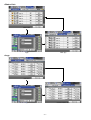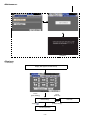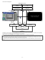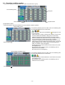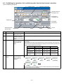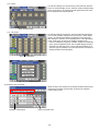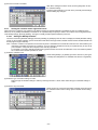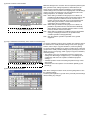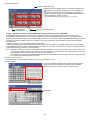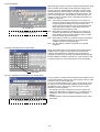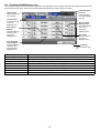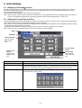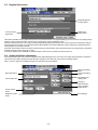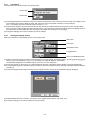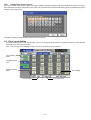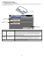
1
Mitsubishi Electric Air-conditioner Network System
Centralized Controller
Model: AG-150A
Instruction Book
1.
2.
3.
4.
CENTRALIZED CONTROLLER AG-150A
Safety precautions ............................................................... 1
Product features................................................................... 2
Component names and display screen names.................... 5
User operation ................................................................... 12
4-1 Operation condition monitor...................................... 13
4-2 Prohibiting the operation of air conditioning units
from the local remote controllers............................... 15
4-3 Setting Schedules ..................................................... 19
4-4 Checking the List of Malfunctioning Units ................. 28
4-5 Checking the List of Units with a Triggered
Filter Sign.................................................................. 29
4-6 Checking the Malfunction Log................................... 30
5. Initial Settings..................................................................... 31
5-1 Bringing up the settings screen................................. 31
5-2 Setting the Current Date and Time ........................... 31
5-3 Register the license .................................................. 32
5-4 Setting the Basic Information .................................... 32
5-5 Network Setting......................................................... 34
5-6 Group Setting............................................................ 36
5-7 Interlocked Setting .................................................... 39
5-8 Block Setting ............................................................. 40
5-9 Floor Layout Setting.................................................. 41
5-10 Checking the refrigerant systems ............................. 43
6. User Setting ....................................................................... 44
6-1 Setting the Maintenance User................................... 44
6-2 Setting the Building Manager.................................... 44
7. Maintenance screen........................................................... 46
7-1 Copying the data to a USB drive............................... 46
7-2 Adjusting the touch panel.......................................... 47
8. Cleaning the touch panel ................................................... 48
9. External input/output function ............................................ 49
9-1 External input function .............................................. 49
9-2 External output function ............................................ 50
9-3 LAN connection function ........................................... 50
10. Specifications..................................................................... 50
Before using the controller, please read this Instruction Book carefully to ensure proper operation.
Keep this manual for future reference.
1. Safety precautions
Before using the controller, read the Safety Precautions section carefully to ensure proper operation.
These safety precautions must be observed by anyone who operates the centralized controller at all times.
Keep this Instruction Book and Installation Manual for future reference. Make sure both this Instruction Book and the
Installation Manual are given to the next user.
WARNING
This symbol indicates that failure to follow the instructions exactly as stated poses the risk of
serious injury of death.
CAUTION
This symbol indicates that failure to follow the instructions exactly as stated poses the risk of
injury or damage to the controller.
WARNING
Have the unit professionally installed.
Improper installation by an unqualified person may result in
a risk of electric shock or fire.
Ask your dealer or an authorized technician to move
the controller.
Improper installation may result in electric shock or fire or
damage to the controller.
Make sure the controller is securely mounted so that it
will not fall.
Controllers must be disposed of properly.
Contact your dealer for proper disposal procedures.
Make sure that the controller is connected to a properly
rated power supply to avoid fire or damage to the
controller.
Do not attempt to modify or repair the controller.
Modification or improper repair may result in electric shock
or fire. Consult your dealer when repairs are necessary.
If any abnormality is noticed (e.g., burning smell), stop
the operation, turn off the power supply, and contact
your dealer or technical representative immediately.
Continuing the operation may result in damage to the
controller, electric shock, or fire.
Stop the operation immediately and notify your dealer
if an error code is displayed and the controller does
not operate, or when any abnormality is noticed.
Continuing the operation may result in damage to the
controller or fire.
CAUTION
Do not install the controller where there is a risk of
leakage of flammable gas.
If the leaked gas accumulates around the controller, it may
be ignited and result in an explosion.
To reduce the risk or electric shock and malfunctions,
do not operate the touch panel with wet hands.
Do not use the controller in an environment high in oil,
steam, or sulfuric gas.
These substances may have adverse effects on the
performance of the controller of damage its parts.
Do not wet the controller.
Water may damage the controller and cause an electric
shock.
To reduce the risk of electric shock or malfunctions, do
not use a pointy or sharp object to operate the touch
panel.
Do not use the controller for specialized applications.
This product is designed exclusively for use with the
MITSUBISHI ELECTRIC building air conditioning control
system. The use of this product with other air-conditioning
management systems or for other purposes may result in
malfunctions.
Operate the controller within the temperature range
specification.
The use of controller outside of its specification may result
in serious damage to the controller. Be sure to check the
temperature range specification in the Instruction Book.
Do not spray insect sprays or sprays with flammable
propellants to the controller.
To avoid the risk of fire or explosion, do not place
flammable sprays near the controller or spray them directly
on the controller.
Use a security device such as a VPN router when
connecting the AG-150A to the Internet to prevent
unauthorized access.
–1–
2. Product features
The controller described in this manual is a centralized controller that can be operated over the Web.
Air conditioning units connected to this controller can be operated or monitored directly from this controller or over the
Web, using a browser software on the computer.
Refer to the Web browser operation manual (separate volume) for how to use the Web functions.
Number of
control unit
Function
Indoor unit or independent OA
processing unit or LOSSNAY
Number of units
(indoor or independent OA
processing unit or LOSSNAY)
Number of remote controllers in
one group
Number of system controllers in
one group
Number of interlocked units
ON/OFF
Operation mode
Fan speed
User Operations Function
Temperature setting
Operation
*1
Air direction and swing
operation
Operating/stopping the
interlocked LOSSNAY units
Schedule
Prohibit local remote control
Filter sign reset
Error reset
Error history reset
External input
Description
Up to 50 units are connectable (including the interlocked units) *2
1-16 units (Indoor unit, independent OA processing unit and LOSSNAY can not
register to the same group.)
1-2
0-4 (including the number of remote controller in one group)
• Number of LOSSNAY units (interlocked unit) that can be interlocked with an
indoor unit (interlocking unit): 1
• Number of indoor units (interlocking unit) that can be interlocked with a
LOSSNAY unit (interlocked unit): 16
The ON/OFF operation can be performed as a collective or per group or per block.
The switch operation for the operation mode setting can be performed as a
collective or per group or per block. (Available modes depend on the model.)
[Selectable operation mode for the indoor unit]
COOL/DRY/FAN/AUTO/HEAT
[Selectable operation mode for the independent ventilation]
HEAT RECOVERY/BY-PASS/AUTO
[Selectable operation mode for Hot water supply equipment]
HEATING/HEATING ECO/HOT WATER/ANTI-FREEZE/COOLING
Up to four fan speeds are available, and the fan speed can be changed collectively,
or for each group or block of indoor units. (The number of available fan speeds
depends on the model (2 speeds, 3 speeds, 4 speeds, and Auto). “Auto” is available
only on the models that support that function.)
Temperature setting can be performed collectively or per group or per block.
[Setting temperature range for air conditioner]
Cool (Dry) operation: 19 ~ 30°C / 67 ~ 87°F
Heat operation:
17 ~ 28°C / 63 ~ 83°F
Auto operation:
19 ~ 28°C / 67 ~ 83°F
[Setting temperature range for Hot water supply equipment]
Heating:
30 ~ 45°C
Heating ECO:
30 ~ 45°C
Hot Water:
30 ~ 70°C
Anti-freeze:
10 ~ 45°C
Cooling:
10 ~ 30°C
Vertical air flow directions (5 directions), auto setting, and swing setting can be
changed collectively, or for each group or block of indoor units. (Available air flow
directions depend on the model. [5 air flow directions and AUTO] are available only
on the models that support those settings.
Interlocked LOSSNAY units (if any) can be operated (at High or Low) or stopped
collectively or for each group or block of indoor units. (Ventilation mode cannot be
selected for the interlocked LOSSNAY units.)
Daily, weekly, or annual scheduling of groups or blocks of units is available.
• Twenty-four patterns of operation schedule can be set per day.
• Two types of weekly schedule are available. Starting/ending dates for each
season can be set.
• Five types of operation patterns (P1-P5) are available per year. Up to 50 dates can
be assigned to each pattern.
• Temperature setting, fan speed setting, airflow direction, can be changed and set
back operation can be performed according to the timer setting.
Operation of certain functions from the local remote controllers can be prohibited
collectively or for each group or blocks of indoor units.
(Applicable functions: ON/OFF, operation mode, temperature setting, filter sign)
Filter sign can be reset for each group or block of indoor units.
Resets the display of error.
Resets the error history (unit error, communication error).
Connects to an external input/output device that stops the units in an emergency,
run or stop the units, permit or prohibit the operation of units collectively. Requires
an external input/output adapter (sold separately).
–2–
Function
User Operations Function
ON/OFF (system)
Operation status of each group
in the system
Monitor
*1
Filter sign
Local operation prohibition
Error
External output
Date and time
License
Initial Settings
Unit Info.
Operation
*1
Network
Groups
Blocks
Interlock
Floor Layout
Other
User Setting
Monitor
*1
Operation
*1
Data
back-up
Error history monitor
Refrigerant system
configuration confirmation
Maintenance User
Building Manager
Description
The ON/OFF indicator lamp indicates if one or more groups or all the groups in the
system are stopped.
Operation status (ON/OFF), operation mode, fan speed, temperature setting, air
flow direction, operation status (ON/OFF) of interlocked units, timer enable/disable
status of each group is displayed.
Indicates that the filter on the units in a given group is due for cleaning.
Displays the functions that the controller forbids or the functions that are forbidden
by other controllers.
The address of the unit in error, error code, and the address of the unit that detected
the error will appear.
Outputs signals (run/stop, error) to an external device. Requires an external input/
output adapter (sold separately).
This function is used to set the current date/time and daylight savings time.
This function is used to register license.
This function is used to set unit name, ID number, brightness of the LCD, sound
volume, date format, time format, temperature unit, and display language.
This function is used to set the IP address, subnet mask address, and gateway
settings for the LAN and also to set the address, K-transmission converter address,
local control prohibit settings, and external input settings for the M-NET.
This function is used to register indoor units, LOSSNAY units, remote controllers, and
lower-level system controllers to a group.
This function is used to register a group to a block.
This function is used to interlock the operation of indoor units and LOSSNAY units.
This function is used to make the basic settings for the floor layout and display position
of the groups.
Up to 128 errors can be stored in memory. (64 unit errors, 64 communication errors)
Allows the user to see which indoor units are connected to each outdoor unit.
Allows the maintenance user name and password to be set.
Allows the building manager name, password, function enable/disable settings to be
made.
Group setting information and interlock setting information are retained, even if power
is turned off.
Retained, even if power is turned off.
Schedule information of each group is retained, even if power is turned off.
Current time is retained by the build-in capacitor for a week, even if power is turned off.
The initial setting data, history data, calculated values, and computed values can be
Saving the data on a USB drive
stored to a USB drive.
Connection/Interlock
Information
Error history
Schedule data
Current time
Device
Touch panel cleaning
maintenance
Touch panel is locked and can be cleaned.
*1: The item and range that can be operated or monitored depend on the function of the indoor unit.
*2: The maximum number of the controllable units varies depending on the indoor unit.
–3–
* Upper-level and lower-level system controllers
The controller described in this manual can only be used as the upper-level controller, but not as a lower-level controller.
• Upper-level system controller (upper-level SC)
Upper-level SC refers to a controller that controls all other system controllers including the units they control.
If a given system has only one system controller, that controller becomes an upper-level controller.
Group settings and interlock settings can only be made from an upper-level controller.
• Lower-level system controller (lower-level SC)
Lower-level controller refers to a system controller that is controlled (including the units it controls) by an upper-level system controller.
AG-150A
management range
M-NET Gateway
management range
Another system controller
management range
Management range
of AG-150A
Unit
Unit
Unit
Unit
When AG-150A controls another system controller or when
the system contains only AG-150A:
AG-150A is set as the main system controller.
*AG-150A performs the group setting in this configuration.
When AG-150A is controlled by another system controller:
(Example: MJ-300Gateway)
AG-150A is set as the sub system controller.
*The group setting is performed by main system controller.
NOTE:
The following group setting cannot be performed.
Unit groups which are not under the management of the main controller and are managed by the sub system
controller.
Main system
controller
Group
Sub system
controller
Group
Group
A common group is managed by mode than two main controllers.
Main system
controller 1
Group
Main system
controller 2
Group
Group
A sub system controller which exceeds the management range of the main system controller of two or more.
Sub system
controller
Main system
controller 1
Group
Group
Main system
controller 2
Group
–4–
Group
3. Component names and display screen names
Power indicator
Unlit .... Power is turned off.
Lit ....... Power is turned on.
ON/OFF indicator lamp
(system)
Displays the operation
status of indoor units
Unlit .... All groups of units
are stopped.
Lit ....... One or more groups
of units are ON.
Blink ... Indicates that an
error occurred.
CENTRALIZED CONTROLLER AG-150A
Display/Touch panel
<Monitor/Operation>
Floor layout (simplified icons)
Air conditioning unit operation screen
Floor layout (icons)
Block display
Login
–5–
<Schedule Settings>
• Setting the schedule without a license registration
Schedule setting screen (floor layout) Weekly
Weekly schedule screen
Schedule setting screen (block display) Weekly
Schedule setting screen (air conditioning units)
Login
–6–
<Schedule Settings>
• Setting the schedule with a license registration
Schedule setting screen (block display)
Weekly 1, Weekly 2
Season setting screen
Schedule setting screen (floor layout)
Weekly 1, Weekly 2
Weekly schedule screen
Schedule setting screen (block display)
Current day/annual
Annual schedule screen
Annual schedule pattern setting screen
Schedule setting screen (floor layout)
Current day/annual
Login
Current day schedule screen
Schedule setting screen (air conditioning units)
–7–
<Status List>
Malfunction
Login
Filter sign
<Log>
Unit error
Login
Communication error
–8–
Login
<Initial Settings>
License
Date and time
System View
Unit Info.
Floor Layout
Blocks
Network
Groups
Interlock
The above nine initial setting screens can be accessed from the sub menu.
<User Info>
Maintenance User
Building Manager
–9–
<Maintenance>
Data Utility
Touch Panel Calibration
Calibration
<Displays>
• Initial startup
Display that appears at initial startup
Date and time
Touch
[Save Setting]
Touch
[User Info]
Initial Settings
Touch [
User Info
Touch
[Initial Settings]
]
Monitor/Operation
– 10 –
• Screen that normally appears
Main operation screen
Touch [
]
Schedule
Log
Monitor/Operation
Status List
Touch
[Cancel]
Touch [
]
Touch 1,2,3,4
Touch
[
Login
Touch
[Login]
Initial Settings
]
Touch panel cleaning screen
Touch
[User Info]
Touch
[Maintenance]
User Info
Touch
[Initial Settings]
Maintenance
Touch
[User Info]
Touch
[Initial Settings]
Touch
[Maintenance]
* Normally, the screen remains black. The backlight turns on when the touch panel is touched and stays on while the user is operating
the touch panel. The backlight goes off after 10 minutes of non-operation.
* When an error occurs, the backlight turns on regardless of whether the user is operating the touch panel.
CAUTION
• If nothing appears on the display after touching the touch panel several times, the LCD backlight may be damaged. Since continued
use may cause malfunctions, stop the operation, and contact the service center.
• Touching two points simultaneously will be interpreted as pressing a different point. To avoid malfunctions, only touch one point at a
time.
– 11 –
4. User operation
Used the following two screens when user operation is performed.
• Floor layout/block display screens ....................Displays the operation status (ON/OFF) and error status of the air conditioning units
This is the screen that is normally used.
• Air conditioning unit operation setting screen....Collective or individual group operation of indoor units are performed on this screen
(ON/OFF, operation mode, air flow direction, fan speed, temperature setting, timer
enable/disable, prohibition/permission of operation from local remote controller,
filter reset, room temperature display).
<Accessing the Floor layout, Block display, and Air conditioning unit operation setting screens>
Block button
Zoom-in button
Refer to Section 4-1 “Operation condition
monitor”.
Zoom-out button
Press
[Zoom-out button]
Press
[Zoom-in button]
Floor layout (simplified icons)
Press [Block].
Operation button
Floor layout (icons)
Press [Block].
Floor button
Press [OK] or
[Cancel].
(Applicable only
when the operation
screen is accessed
Press [Floor].
from the Block
display screen)
Select a group and
press [Operate].
Select a group and
press [Operate].
Press [OK] or
[Cancel].
(Applicable only
when the operation
screen is accessed
from the Block
display screen)
Block display
OK button
Operation
button
Cancel button
Air conditioning unit
operation screen
Refer to Section 4-1 “Operation condition
monitor”.
Refer to Section 4-2 “Prohibiting the operation of
air conditioning units from the local remote
controllers”.
– 12 –
4-1 Operation condition monitor
• This function displays the ON/OFF/Malfunction status of specific units or group.
Floor-switching button
Group icon
Operation button
Zoom-out button
(1) Operation method
• Note that operation methods are different for group operation and block operation.
<Group display (icon)>
The operation (ON/OFF) and error status of the air conditioning units
can be checked with the icons on the screen.
(
* If there is a device that cannot be identified,
will appear over the
icon of the device.
• Click on the icon of a group, and then click “Operate” to go into the
screen that allows the operation of that group. On the screen,
detailed information about the temperature, fan speed, air flow
direction, prohibit/permit status of the remote controller, and mode
can be checked. (If air conditioning unit group, ventilation
equipment (LOSSNAY) group, general equipment group, and Hot
Water Supply group are included in the selected group, a screen will
appear, asking the user to select a group. Once the selection is
made, an operation screen will appear.)
• Pressing the Zoom-out button takes the screen back to the screen
with simplified icons.
• By pressing the floor switching button, air conditioning units on
other floors can be checked.
(Several types of icons will appear.)
Zoom-out button
<Group display (simplified icons)>
The operation (ON/OFF) and error status of the air conditioning units
can be checked with the icons on the screen.
• Pressing the Zoom-in button will take the screen back to the screen
with simplified icons.
• By pressing the floor switching button, air conditioning units on
other floors can be checked.
Zoom-in button
– 13 –
<Block display>
The operation (ON/OFF) and error status of the air conditioning units
can be checked with the icons on the screen.
(
* If there is a device that cannot be identified,
will appear over the
icon of the device.
• Click on the icon of a group, and then click “Operate” to go into the
screen that allows the operation of that group. On the screen,
detailed information about the temperature, fan speed, air flow
direction, prohibit/permit status of the remote controller, and mode
can be checked.
• Press the scroll button and to see the status of the rest of the blocks
that are not shown on the screen. (Several types of icons will
appear.)
Scroll button
– 14 –
4-2 Prohibiting the operation of air conditioning units from the local remote controllers
(1) Air conditioning unit group
ON/OFF switch
Operation mode switch
Operation status of
interlocked unit
Fan speed of
interlocked unit
Temperature
Fan Speed
Air Direction
Remote operation
prohibit switch
Function
Filter sign reset
OK
Operation method
Cancel
Display
1
ON/OFF
Select the operation
status (ON or OFF).
An orange frame will appear around the selected button.
2
MODE
Select the desired
operation mode from
one of the icons below
“Mode”.
An orange frame will appear around the selected mode.
3
Set Temperature Set the temperature by
using the Up/Down
arrows below “Set
Temp”.
Pressing the Up/Down arrow increases/decreases the temperature by one degree
respectively.
The settable temperature range depends on the mode and model. If the Up arrow is
pressed when the upper limit temperature is displayed. the lower limit temperature will
appear, and the Down arrow vice versa.
Model
Standard temp
model
Mid temp model
(CITY MULTI)
Mid temp model
(Mr. Slim)
4
Air Direction
Setting
Cooling/Dry
19 ~ 30°C
[67 ~ 87°F]
14 ~ 30°C
[57 ~ 87°F]
14 ~ 30°C
[57 ~ 87°F]
Heating
17 ~ 28°C
[63 ~ 83°F]
17 ~ 28°C
[63 ~ 83°F]
14 ~ 28°C
[57 ~ 83°F]
Auto
19 ~ 28°C
[67 ~ 83°F]
17 ~ 28°C
[63 ~ 83°F]
14 ~ 28°C
[57 ~ 83°F]
Set the air flow direction 5-speed model
with the Up/Down
arrows below “Air
Direction”.
(Mid 3)
(Mid 2)
(Mid 1)
(Mid 0)
(Horizontal)
(Swing)
(Auto)
(Swing and Auto are not available on some models. Depending on the model four or
five air flow directions are available.)
– 15 –
Function
5
Fan speed
Operation method
Use the Up/Down
arrows below “Fan
Speed” to set the fan
speed.
Display
4-speed model:
(Low)
(Mid 2)
(Mid 1)
(High)
(Auto)
(“Auto” is not available on some models. Some models of units have only two or
three fan speeds.)
6
Remote Prohibit
controller
Pressing of each button toggles through the following three options:
Press the button that
Retention of current status o Permit o Prohibit
corresponds to the
desired function and
Retention of
setting to permit or
Permit
Prohibit
current
status
prohibit the operation
from the remote
ON/OFF
controller. The functions
that can be prohibited
are as follows: ON/OFF,
Operation mode
operation mode,
temperature, and filter
Temperature
sign reset.
setting
Filter sign reset
7
Filter sign reset
Press “Reset” under
“Filter Sign”.
Filter cleaning warning sign will be cleared. (Cumulative operation time is reset.)
8
Ventilation ON/
OFF
An orange frame will appear around the selected operation status.
Select the ON/OFF
status for the interlocked
unit.
9
Ventilation Fan
speed
Set the fan speed with
the Up/Down arrows
below “Fan Speed”.
2-speed model:
(Low)
(High)
(Fan speed setting is not available on some models.)
10
OK
Press the OK button to
reflect the change.
Pressing the OK button saves the setting and takes the screen back to the previous
screen (Floor layout or Block display).
11
Cancel
Press the Cancel button Pressing the Cancel button cancels the change and takes the screen back to the
to cancel the change.
previous screen (Floor layout or Block display).
– 16 –
(2) Ventilation equipment (LOSSNAY) group
ON/OFF switch
Operation mode switch
Fan Speed
Remote operation
prohibit switch
Function
Filter sign reset
OK
Operation method
Cancel
Display
1
ON/OFF
Select the operation
status (ON or OFF).
An orange frame will appear around the selected button.
2
MODE
Select the desired
operation mode from
one of the icons below
“Mode”.
An orange frame will appear around the selected mode.
3
Fan speed
Use the Up/Down
arrows below “Fun
Speed” to set the fan
speed.
2-speed model:
o
o
(Low)
o…
(High)
(Fan speed setting is not available on some models.)
4
Remote Prohibit
controller
Pressing of each button toggles through the following three options:
Press the button that
Retention of current status o Permit o Prohibit
corresponds to the
desired function and
Retention of
setting to permit or
Permit
Prohibit
current
status
prohibit the operation
from the remote
ON/OFF
controller. The functions
that can be prohibited
are as follows: ON/OFF
Filter sign reset
and filter sign reset.
5
Filter sign reset
Press “Reset” under
“Filter Sign”.
Filter cleaning warning sign will be cleared. (Cumulative operation time is reset.)
6
OK
Press the OK button to
reflect the change.
Pressing the OK button saves the setting and takes the screen back to the previous
screen (Floor layout or Block display).
7
Cancel
Press the Cancel button Pressing the Cancel button cancels the change and takes the screen back to the
to cancel the change.
previous screen (Floor layout or Block display).
– 17 –
(3) Hot water supply equipment group
ON/OFF switch
Operation mode switch
Temperature
Remote operation
prohibit switch
Function
Circulating water
replacement sign reset
OK
Operation method
Cancel
Display
1
ON/OFF
Select the operation
status (ON or OFF).
An orange frame will appear around the selected button.
2
MODE
Select the desired
operation mode from
one of the icons below
“Mode”.
An orange frame will appear around the selected mode.
3
Set Temperature Set the temperature by
using the Up/Down
arrows below “Set
Temp”.
4
Remote Prohibit
controller
Pressing the Up/Down arrow increases/decreases the temperature by one degree
respectively.
The settable temperature range depends on the mode and model. If the Up arrow is
touched when the upper limit temperature is displayed.
The lower limit temperature will appear, and the Down arrow vice versa.
• Heating mode:
30°C ~ 45°C
• Heating ECO mode: 30°C ~ 45°C
• Hot Water mode:
30°C ~ 70°C
• Anti- freeze mode:
10°C ~ 45°C
• Cooling mode:
10°C ~ 30°C
* Temperatures are displayed Fahrenheit if Fahrenheit is selected.
Pressing of each button toggles through the following three options:
Press the button that
corresponds to each of Retention of current status o Permit o Prohibit
the following buttons to
Retention of
permit or prohibit access
Permit
Prohibit
current status
to these functions: ON/
OFF, operation mode,
ON/OFF
temperature, and
circulating water
replacement.
Operation mode
Temperature
setting
Circulating water
replacement
5
Circulating water Press the OK button with The circulating water replacement sign is reset.
replacement
the circulating water
sign reset
replacement sign reset
button being touched.
6
OK
Press the OK button to
reflect the change.
7
Cancel
Press the Cancel button Pressing the Cancel button cancels the change and takes the screen back to the
to cancel the change.
previous screen (Floor layout or Block display).
Pressing the OK button saves the setting and takes the screen back to the previous
screen (Floor layout or Block display).
– 18 –
4-3 Setting Schedules
4-3-1
Setting the schedule without a registered license
If a license has not been acquired, only the weekly schedule functions available.
• Setting the Weekly Schedule
Touch the menu item [Schedule Settings] and click [Weekly] in the sub menu to display the Weekly Schedule setting screen. To set a
weekly schedule, you first must select what will be the target of this schedule and then set the schedule details from Sunday right
through to Saturday.
Note: When the contents of an operation are executed as part of a schedule these contents will continue to be in effect until they are
changed by a schedule or browser etc. Therefore, if you are setting a schedule that is only for a particular day, be sure to set your
schedule in a way that will not impact on the next day’s operation.
For example, if you wish to prohibit operations being performed from the remote controller after 17:00, set a Prohibit operation for
17:00 and set an Enable operation for 23:59.
(1) Select the type of schedule settings to make.
(1-1) Group
To make the settings for a group, select the group by touching the
corresponding icon on the weekly schedule setting screen (floor
layout or block display). Multiple groups can be selected. An orange
frame appears on the group that has been selected. Selection can be
cancelled by touching the icon again. Touch the Cancel button to
deselect all.
* Each group is represented with an icon and a group name.
(1-2)
Floor
To make the settings for all groups on a given floor, select the floor on
the floor layout screen under the weekly schedule setting screen
menu, and touch the Select-all-units-on-the floor button. An orange
frame will appear around the icons of all groups on the selected floor,
and also around the floor selection button. Only a single floor can be
selected at a time.
Floor selection button
Select-all-units-on-the floor button
– 19 –
(1-3)
Block
To make the settings for a block or blocks, select the block selection
button on the block display screen under the weekly schedule setting
screen by touching it. An orange frame will appear around the icons
that correspond to the selected blocks.
Block selection button
(1-4)
All groups
To make the settings for all groups, touch the Select-all-units button
on the weekly schedule setting screen (floor layout or block display
screen). An orange frame appears around the icons of all groups.
After making the selection, touch the [Edit] button at the right bottom
corner of the screen to bring up the weekly schedule screen.
* If the air conditioning unit group, ventilation equipment (LOSSNAY)
group, general equipment group, and Hot Water Supply group are
included in the selected group, a screen will appear asking you to
select the type of equipment. Once the selection has been made, a
weekly schedule screen will appear.
Select-All-Units button
Equipment type selection screen
(2) Select the day of the week
Select the days of the week from the weekly schedule setting screen
and touch the schedule content button to bring up the schedule
content setting screen.
Schedule content button
Days of the week menu
– 20 –
(3) Set the contents of the schedule
(Air Conditioner)
Make the settings for the execution time, operation patterns (ON/OFF,
operation mode, setting temperature, airflow direction, fan speed,
remote controller operation prohibition) on the schedule content
setting screen, and then touch the [OK] button. Not all settings need to
be made. The settings for only the operation mode or the setting
temperature, for example, can be made.
Note: When setting a schedule for all groups or for a block, it is
possible to set all operation modes such as Auto mode etc, but
if some targeted air conditioner units do not have such a
function, then those units will not run in the specified mode.
When setting the schedule, consider what functions are
supported by the air conditioner units.
Note:
When setting a schedule for all groups or for a block, it is
OK button
possible to set prohibit remote controller items individually.
When allowing remote controller operation under K control,
however, all items must be set enable.
Note: When setting a schedule for ventilator units, the temperature
setting is not displayed. Moreover, the prohibit remote
controller operation is simply [ON/OFF].
Note: Only the ON/OFF operation is possible on the general
equipment.
(LOSSNAY)
(Hot Water Supply)
(4) Copy a schedule to another day of the week or to another group
Copy button
Paste button
To copy the schedule of a given day to another day, select the days of
the week from the weekly schedule setting screen, touch [Copy] to
select it, select a day to copy the schedule to, and touch [Paste].
To copy the weekly schedule for one group to another group, select
the group from the weekly schedule setting screen (Floor layout or
block display screen), touch [Copy], select a group to copy the
schedule to, and touch [Paste].
* The settings of one type of equipment cannot be copied to the
settings of a different type of equipment. (i.e., The settings of air
conditioning units cannot be copied to ventilation equipment
settings.)
* Available operation modes and setting temperature range varies
with models.
– 21 –
(5) Save the contents of schedule
After all the settings have been made, touch the [OK] button to save
the schedule settings.
Touch the [Cancel] button to go back to the previously saved settings
without making any changes.
4-3-2
Setting the schedule with a registered license
When a license is registered, it is possible to set different weekly (2 types)/annual/today’s schedules for each air conditioner group.
Moreover, for any weekly/annual/today’s schedule run for a particular day, the priority in which it is run will be from the highest and the
order will be [Today’s], [Annual], [Weekly]. Two types of weekly schedule (Summer/Winter) can be set.
4-3-2-1
Setting the Weekly Schedule
Touch the menu item [Schedule Settings] and touch [Weekly1] or [weekly2] in the sub menu to display the Weekly Schedule setting
screen. To set a weekly schedule, you first must select what will be the target of this schedule and then set the schedule details from
Sunday right through to Saturday.
Note: When the contents of an operation are executed as part of a schedule these contents will continue to be in effect until they are
changed by a schedule or browser etc. Therefore, if you are setting a schedule that is only for a particular day, be sure to set
your schedule in a way that will not impact on the next day’s operation.
For example, if you wish to prohibit operations being performed from the remote controller after 17:00, set a Prohibit operation
for 17:00 and set an Enable operation for 23:59.
(1) Select the schedule to set.
Select either [Weekly 1] or [Weekly 2] from the sub menu. (Two types
of weekly schedule patterns are available if the license is registered.)
(2) Select the type of schedule settings to make.
Select the type of schedule settings to make by referring to Section 1 above under “Select the type of schedule settings to
make.”
(3) Select the day of the week
Select the days of a week from the weekly schedule screen and touch
the schedule content button to bring up the schedule content setting
screen.
Schedule content button
– 22 –
(4) Set the contents of the schedule
(Air Conditioner)
Refer to 4-3-1 (3) for the figure of LOSSNAY and
hot water supply equipment.
Make the settings for the execution time and operation patterns (ON/
OFF, operation mode, setting temperature, airflow direction, fan
speed, remote controller operation prohibition) on the schedule
content setting screen, and then touch the [OK] button. Not all settings
need to be made. The settings for only the operation mode or the
setting temperature, for example, can be made.
Note: When setting a schedule for all groups or for a block, it is
possible to set all operation modes such as Auto mode etc, but
if some targeted air conditioner units do not have such a
function, then those units will not run in the specified mode.
When setting the schedule, consider what functions are
supported by the air conditioner units.
Note: When setting a schedule for all groups or for a block, it is
possible to set prohibit remote controller items individually.
When allowing remote controller operation under K control,
however, all items must be set enable.
Note: When setting a schedule for ventilator units, the temperature
setting is not displayed. Moreover, the prohibit remote
controller operation is simply [ON/OFF].
Note: Only the ON/OFF operation is possible on the general
equipment.
(5) Copy a schedule to another day of the week or to another group
Refer to the figures under 4-3-1 (4) for how to copy
the schedule of one group to another.
To copy the schedule of a given day to another day, select the days of
the week from the weekly schedule setting screen, touch [Copy] to
select it, select a day to copy the schedule to, and touch [Paste].
To copy the weekly schedule of one group to another group, select the
group from the weekly schedule setting screen (Floor layout or block
display screen), touch [Copy], select a group to copy the schedule to,
and touch [Paste].
* The settings of one type of equipment cannot be copied to the
settings of a different type of equipment. (i.e., The settings of air
conditioning units cannot be copied to ventilation equipment
settings.)
* Available operation modes and setting temperature range varies
with models.
* Schedules cannot be copied to or from between [Weekly 1] and
[Weekly 2].
(6) Save the contents of schedule
After all the settings have been made, touch the [OK] button to save
the schedule settings.
Touch the [Cancel] button to go back to the previously saved settings
without making any changes.
– 23 –
(7) Define the seasons
Weekly 1: Applicable period
Pressing the Season Settings button on the schedule setting screen
(
) will bring up the Season Settings screen, and the duration of
each seasons can be defined, to which [Weekly 1] or [Weekly 2]
schedules are applied.Touch the “Enable/disable switching button” to
enable or disable the “Weekly 2” setting.
* The period setting can go past 12/31 (i.e., 11/1~3/31).
Enable/disable
switching button
4-3-2-2
Weekly 2: Applicable period
Setting the annual schedule (Applicable only when the license is registered)
Selecting [Schedule Setting] from the main menu on the [Main operation screen] will bring up the schedule setting screen.
Subsequently, selecting [Annual] from the sub menu will bring up the annual schedule setting screen. You can use the annual
schedule to set schedules for days such as public holidays and summer vacation that need to be scheduled differently to the weekly
schedule. For each air conditioner group, it is possible to set 50 day-long settings up to 24 months into the future (including the
current month).
Settings for days that have passed will be deleted automatically.
To make the settings for the annual schedule, first select the item to be set, and then touch [Edit] to bring up the annual schedule
screen. Make the settings for the five patterns (pattern A through E) on the weekly schedule screen, and then assign those patterns
to appropriate dates (e.g., holidays, or summer break).
Note: When the contents of an operation are executed as part of a schedule these contents will continue to be in effect until they are
changed by a schedule or browser etc. Therefore, if you are setting a schedule that is only for a particular day, be sure to set
your schedule in a way that will not impact on the next day’s operation.
For example, if you wish to prohibit operations being performed from the remote controller after 17:00, set a Prohibit operation
for 17:00 and set an Enable operation for 23:59.
(1) Select the item to be set.
As with the weekly schedule setting, select the item to be set. (Refer to 4-3-1 (1).)
(2) Select a pattern.
Touching the alphabetic letters in the calendar or touching the Edit
button in the annual schedule screen will bring up the schedule
pattern setting screen. Select the pattern you want to edit.
Edit schedule patterns
Pattern Menu
– 24 –
(3) Edit the patterns.
(Air Conditioner)
Refer to 4-3-1 (3) for the figure of LOSSNAY and
hot water supply equipment.
After selecting the pattern, touch the schedule content button to bring
up the schedule content setting screen. Make the settings for the
execution time and operation patterns (ON/OFF, operation mode,
setting temperature, airflow direction, fan speed, remote controller
operation prohibition) on the schedule content setting screen, and
then touch the [OK] button. Not all settings need to be made. The
settings for only the operation mode or the setting temperature, for
example, can be made.
Note: When setting a schedule for all groups or for a block, it is
possible to set all operation modes such as Auto mode etc, but
if some targeted air conditioner units do not have such a
function, then those units will not run in the specified mode.
When setting the schedule, consider what functions are
supported by the air conditioner units.
Note: When setting a schedule for all groups or for a block, it is
possible to set prohibit remote controller items individually.
When allowing remote controller operation under K control,
however, all items must be set enable.
Note: When setting a schedule for ventilator units, the temperature
setting is not displayed. Moreover, the prohibit remote
controller operation is simply [ON/OFF].
Note: Only the ON/OFF operation is possible on the general
equipment.
(4) Assign schedule patterns to special dates.
Assign the schedule patterns to the dates to which regular weekly
schedule does not apply, such as holidays and summer break.
Touch the desired date on the calendar to see which pattern is
assigned to the date. Each touching of the button will cycle through
the letters ABCDE and blank, then back to A. Touch the button until
you get the pattern you want. Select blank to cancel the selection.
Date button
(5) Copy a schedule to another pattern or to another group
Refer to the figures under 4-3-1 (4) for how to copy
the schedule of one group to another.
To copy a pattern to another, select the pattern from the pattern menu
on the schedule pattern setting screen, touch [Copy] to select it, select
a pattern to copy to, and touch [Paste].
To copy the annual schedule for one group to another group, select
the group from the annual schedule setting screen (Floor layout or
block display screen), touch [Copy], select a group to copy the
schedule to, and touch [Paste].
* The settings of one type of equipment cannot be copied to the
settings of a different type of equipment. (i.e., The settings of air
conditioning units cannot be copied to ventilation equipment
settings.)
* Available operation modes and setting temperature range varies
with models.
– 25 –
(6) Save the contents of schedule
After all the settings have been made, touch the [OK] button to save
the schedule settings.
Touch the [Cancel] button to go back to the previously saved settings
without making any changes.
4-3-2-3
Setting the current date schedule
Selecting [Schedule Setting] from the main menu on the [Main operation screen] will bring up the schedule setting screen.
Subsequently, selecting [Today] from the sub menu will bring up the current day schedule setting screen. By using this function,
schedule for the current date can be set without having to change the weekly or annual schedule. First select the item to be set, and
then set the schedule.
Note: When the contents of an operation are executed as part of a schedule these contents will continue to be in effect until they are
changed by a schedule or browser etc. Therefore, if you are setting a schedule that is only for a particular day, be sure to set
your schedule in a way that will not impact on the next day’s operation.
For example, if you wish to prohibit operations being performed from the remote controller after 17:00, set a Prohibit operation
for 17:00 and set an Enable operation for 23:59.
(1) Select the item to be set.
As with the weekly schedule setting, select the item to be set. (Refer to 4-3-1 (1).)
(2) Set the contents of the schedule
Touch the schedule content button on the current day schedule
screen to bring up the schedule content setting screen. Make the
settings for the execution time and operation patterns (ON/OFF,
operation mode, setting temperature, airflow direction, fan speed,
remote controller operation prohibition) on the schedule content
setting screen, and then touch the [OK] button. Not all settings need to
be made. The settings for only the operation mode or the setting
temperature, for example, can be made.
Note: When setting a schedule for all groups or for a block, it is
possible to set all operation modes such as Auto mode etc, but
if some targeted air conditioner units do not have such a
function, then those units will not run in the specified mode.
When setting the schedule, consider what functions are
supported by the air conditioner units.
Note: When setting a schedule for all groups or for a block, it is
possible to set prohibit remote controller items individually.
When allowing remote controller operation under K control,
however, all items must be set enable.
Note: When setting a schedule for ventilator units, the temperature
setting is not displayed. Moreover, the prohibit remote
controller operation is simply [ON/OFF].
Note: Only the ON/OFF operation is possible on the general
equipment.
(Air Conditioner)
Refer to 4-3-1 (3) for the figure of LOSSNAY and
hot water supply equipment.
– 26 –
(3) Copy a schedule to another group
To copy the settings of the current day schedule in one group to
another, select the group from the current day schedule setting screen
(Floor layout or block display screen), touch [Copy], select a group to
copy the schedule to, and touch [Paste].
* The settings of one type of equipment cannot be copied to the
settings of a different type of equipment. (i.e., The settings of air
conditioning units cannot be copied to ventilation equipment
settings.)
* Available operation modes and setting temperature range varies
with models.
(4) Save the contents of schedule
After all the settings have been made, touch the [OK] button to save
the schedule settings.
Touch the [Cancel] button to go back to the previously saved settings
without making any changes.
– 27 –
4-4 Checking the List of Malfunctioning Units
Touch the [Status list] in the main operation screen menu, and then touch [Malfunction] to see a list of units that are currently in error.
Floor name or
Block name
Number of
malfunctioning
units
The number of
malfunctioning
units is displayed
here.
Group name
The name of the
group is displayed
here.
Unit address
The unit address is
displayed here.
Error code
The error code is
displayed here.
All reset
Item
Description
All reset
Touch [All Reset] when you want to reset the errors on all the malfunctioning units at once.
Number of malfunctioning units
The number of malfunctioning units is displayed.
Group Name
The name of the group that the unit in error belongs to appears here.
Note: If a unit, such as an outdoor unit or system controller, has not been registered in a group that
is the object of the operation, this area will be blank.
Unit address
The address of the unit in error appears here.
Error code
The error code of the error that is causing the malfunction is displayed. Touch the error code to see
the explanation.
Error code display
Explanation of error
– 28 –
4-5 Checking the List of Units with a Triggered Filter Sign
Touching [Status List] on the Main operation screen and then touching [Filter signs] in the sub menu will bring up a list of units whose
filter sign is turned on.
Floor name or
Block name
Number of units
with triggered
filter signs
The number of
units with currently
triggered filter
signs is displayed
here.
Group name
The name of the
group is displayed
here.
Unit address
The unit address is
displayed here.
Reset units
individually
Touch to reset the
filter sign for the
group the units
belong to.
All reset
Touch to reset the filter
sign on all units with
triggered filter signs.
Item
Description
All reset
Touch [All Reset] when you want to reset the filter sign on all units with a triggered filter sign at once.
Reset units individually
Touch [Reset] when you want to reset the filter sign for the group the units belong to.
Number of units withtriggered
filter signs
The number of units with currently triggered filter signs is displayed.
Group Name
The name of the group appears here that contains the unit whose filter sign is turned on.
Unit address
The address of the units with its filter sign turned on appears here.
– 29 –
4-6 Checking the Malfunction Log
Touch the [Unit error] in the sub menu under [Log] on the main operation screen to see the unit error history (latest 64 events). Click
[Communication error] in the sub menu to see the M-NET transmission error history (latest 64 events).
Communication
error log
Touch to display
the communication
error log.
Unit error log
Click to display the
unit error log.
Occurred time
The date and time
of error is
displayed here.
Error recovery
date and time
The date and time
of the error
recovery is
displayed here.
Error source
address
The unit address of
where the error
occurred is
displayed here.
Error code
The error code of
the error is
displayed here.
Error detection
source address
The unit address of
where the error
was detected is
displayed here.
Clear log
Click to clear the error
log.
Item
Description
Unit error log
Touch [Unit Error] to display the unit error log.
Communication error log
Touch [Communication Error] to display the M-NET communication error log.
Clear log
Touch [Clear Log] to clear the error log that is being displayed.
Time Occurred
The date and time of when the error occurred is displayed.
Error source address
The unit address of where the error occurred is displayed.
Error detection source address
The unit address of where the error was detected is display.
Error code
The error code of the error is displayed.
Time Recovered
The date and time of the error recovery is displayed.
– 30 –
5. Initial Settings
5-1 Bringing up the settings screen
Touching the setting change button [
] at the right top corner of the main operation screen will bring up the login screen. Enter the
user name and password by touching each button, then touch the login button. If the user name and the password are correct, the
setting change window will appear.
* Use the keyboard that appears to enter user name and password.
Note: When the power to the AG-150A is turned on for the first time, the Language Selection screen will appear (Refer to section 5-4-2
(4)). Once the display language has been selected, the Date and Time screen will appear (Refer to section 5-2).
5-2 Setting the Current Date and Time
Touch [Initial settings] on the setting change window, and then touch [Date and Time] on in the sub menu to bring up the date/time setting
screen. Enter the date and time, and touch [Save Settings] to save the settings.
* If the current time is moved forward while the scheduled operation is performed, the operation that was scheduled to take place during
the time that was skipped will not be performed.
* Changing the date and/or time when the charging function is in use can affect the calculation of the charges.
Note: If the user logs in as a building manager, some of the operations may be prohibited.
Menu
Sub Menu
Current date/time
Enter the current
date and time
here.
Custom setting
button
Summer time
setting
Click to set the
daylight saving
time.
Save settings
Click to set the
current date and
time.
Item
Description
Current date/time
Use the up/down buttons to set the date and time.
Summer time setting
This button is used to set Daylight Saving Time. Select your country from the list of countries that
appears when this button is touched. Select [----] when this function is not used. To enter a country
name that is not on the list, select [Custom settings] and manually enter the country name.
Custom setting
Set the beginning and the ending date/time of the daylight saving time if [Custom settings] is selected
to manually enter a country name.
Save Settings
Touch the [Date/Time Set] button to set the current date and time.
– 31 –
5-3 Register the license
Selecting Optional
Function button
Register the
license button
License number
input button
This section describes how to register the license for the optional functions. Touch [Initial Settings] on the menu bar in the setting change
window, and then touch [License] in the sub menu to bring up the license registration screen.
Select the optional functions to be used by touching the [Selecting Optional Function] button, touch the [License number input button],
and enter the license number. The optional functions will be added if the entered registration number matches the registered number
when [Register the license] is touched.
If this fails, check that the license number is entered correctly, that the selection of the optional functions are made properly, and that the
time/date settings on AG-150A is set correctly.
Consult your dealer for the availability of optional functions and for how to purchase the license for them.
5-4 Setting the Basic Information
Touch the [Unit Info.] tab in the screen that appears when [Initial Settings] on the menu bar in the setting change window is touched to
open the Unit Info setting window and make the basic settings for AG-150A such as its name and display options.
Note: If the user logs in as a building manager, the operations may be prohibited.
Date format setting
button
Time format setting
button
Name field button
Temperature unit
setting button
Unit ID field button
Language
selection button
Test run enable/
disable button
Volume control
button
Save Settings
Brightness control
button
– 32 –
5-4-1
Unit Setting
Information about the unit is entered on the window below.
Name button
Unit ID button
(1) Press the [Name] button and enter the name for AG-150A in 40 characters or less. The name set here is used on the display screen
of the software that controls multiple AG-150A units and for the name of the sender in the body of error messages.
Note: The following characters cannot be used in the name: < > & " '
(2) Press the [Unit ID] button and enter the ID number for AG-150A in six numerical characters (single byte) or less. Use this setting
when you want to control multiple AG-150A units with unit IDs. The unit ID that is entered here will be used on the display screen of
the software that controls multiple AG-150A units and for the sender ID in the body of error messages.
(3) Press [Save settings] on the Unit Info window to save the settings.
5-4-2
Setting the Display Format
Data, time, temperature, and language are set on the window below.
Date button
Time button
Temperature button
Language button
Test run enable/disable button
(1) Select the date format. Each touching of the button allows you to cycle through the following options: [31/12/yyyy][12/31/yyyy][yyyy/
12/31]. Current year will appear in “yyyy.” (e.g., December 31st, 2009 will appear as 31/12/2009.)
The date will be displayed in the selected order on the screen or on the mail screen.
(2) Set the time format. (24 hr [18:00] or 12 hr [06:00 PM]) Each touching of the button switches between [18:00] and [06:00 PM].
(3) In the [Temperature] section, select between [°C] and [°F] as the unit of temperature. Each touching of the button switches between
[°F] and [°C].
(4) Press the language selection button to bring up the [Language selection screen], and the selected language will appear.
(5) Enables/disables the test run function. Touching the button toggles between [Not in use] and [In use].
(6) Press [Save setting] on the Unit info window to save the setting.
– 33 –
5-4-3
Adjusting the sound volume and screen brightness
Sound volume and screen brightness are adjusted on this window.
Sound button
Brightness button
(1) Each touching of the sound volume control button cycles through the following: [Level 0], [Level 1], [Level 2], and [Level 3]. Although
the change made in sound volume is reflected right away, it will not be saved until the [Save setting] button is touched. Even if the
setting is changed, if the user exits the window without touching the [Save setting] button, the volume setting will go back to the
previous setting.
(2) Each touching of the brightness control button cycles through the following: [70 %], [80 %], [90 %], and [100 %]. Although the change
made in brightness is reflected right away, it will not be saved until the [Save setting] button is touched. Even if the setting is changed,
if the user exits the window without touching the [Save setting] button, the brightness setting will go back to the previous setting.
(3) Press [Save setting] on the Unit info window to save the setting.
5-5 Network Setting
Touch the [Network] tab in the screen that appears when [Initial Settings] on the menu bar in the setting change window is touched to
open the network setting window and make the basic settings for LAN and M-NET.
Note: If the user logs in as a building manager, some of the operations may be prohibited.
M-NET address
input button
IP address input
button
K converter
address input
button
Controller setting
(prohibition of local
control)
Subnet mask
input button
Gateway address
input button
External input
setting button
Save Settings
5-5-1
LAN setting
In Network Setting, set the AG-150A IP address, subnet mask and gateway address. If connecting to the AG-150A via a permanent
LAN, consult with the network administrator before setting these addresses.
5-5-1-1
Settings for when the AG-150A is connected to a dedicated LAN
(1) Set the IP address for AG-150A. Enter the IP address on the keyboard that appears when the IP address input button is touched.
If the LAN wiring has been newly set up, allocate IP addresses to the AG-150A units in a sequential order starting with
[192.168.1.1]. For example the first AG-150A unit will receive an IP address of [192.168.1.1], the second AG-150A unit will
receive an IP address of [192.168.1.2] and so on.
The Web Monitor PC that monitors and sets AG-150A will also require network addresses consistent with the rest of the LAN.
Note: When using a AG-150A dedicated LAN, it is recommended to set the IP address as follows.
AG-150A: Between [192.168.1.1] and [192.168.1.40] Web Monitor PC: Between [192.168.1.101] and [192.168.1.150]
IP Address button
(2) Set the subnet mask. Enter the subnet mask address for the AG-150A on the keyboard that appears when the subnet mask input
button is touched. Normally, you should enter [255.255.255.0].
Subnet Mask button
– 34 –
(3) When monitoring remotely or sending error mail via a dial-up router, enter the router IP address in the [Gateway] field. Leave the
gateway address blank when not connecting via a dial-up router.
Note: It is recommended to set the dial-up router IP address to [192.168.1.254]. Refer to the dial-up router instruction manual for
details of how to set the IP address.
Note: It is necessary to connect a modem (analog type or ISDN type) between the dial-up router and telephone line when using
a dial-up router that does not have a built-in modem.
Gateway Address button
(4) Press [Save setting] on the network window to save the setting.
5-5-1-2
Settings for when the AG-150A is connected to an existing LAN
When connecting the AG-150A to an existing LAN, consult with the network administrator who is responsible for the LAN before
setting the IP address, subnet mask, or gateway address.
5-5-2
M-NET Setting
In M-NET Setting, set the AG-150A M-NET address, whether or not a K-Control unit is present and which machines send the prohibited
controller command.
M-NET Address button
K Converter Address button
Range of Prohibited Controllers
button
(1) Enter the AG-150A M-NET address in the [M-NET Address] field. Normally you should enter [0].
(2) When K-Control air conditioners are connected, enter the M-NET address of K transmission converter in the [K Converter Address] field.
(3) If prohibited controller (prohibiting local operation) has been set, this setting determines the scope of this setting s control, i.e. operation is prohibited for
both the remote control and subordinate system controllers, or just for the remote control. Click [SC/RC] when you want prohibited controllers to include
both subordinate system controllers and the remote control, or touch [RC only] when you only want to prohibit operation on the remote control.
Note: Normally, you should select [SC/RC].
(4) Press [Save setting] on the network window to save the setting.
5-5-3
External input Setting
The external input function allows for a batch operation (start/stop) of the air conditioning units that are connected to the AG-150A via the
external input/output adaptor (PAC-YG10HA; sold separately), using contact and pulse signals.
Pressing the “External Input Setting” button toggles through the following options: Not in use, Emergency Stop (Level signal), ON/OFF
(Level signal), and ON/OFF/Prohibit/Permit (Pulse signal).
* See Chapter 8 for detailed explanations on how to connect external devices.
External Input Setting button
– 35 –
5-6 Group Setting
Touch the [Groups] tab in the screen that appears when [Initial Settings] on the menu bar in the setting change window is touched to open the
group setting window and set and register the group names for the air conditioning units or general equipment to be connected to AG-150A.
Note: If the user logs in as a building manager, some of the operations may be prohibited.
Note: If the system is connected to the TG-2000A, make all settings and changes from the TG-2000A so that the data in TG-2000A and
AG-150A will match.
Note: A contact on the genera interface device is regarded as one unit. The number of units that can be connected to AG-150A is up to 50.
Note: Air-conditioners and general equipment cannot be in the same group.
Note: Remote controllers or system controllers cannot be connected to general equipment.
Group No.
Group numbers
will be displayed
here.
Remote controller
selection button
Group Name
Input button
System controller
selection button
Unit selection
button
Save Setting
button
5-6-1
Setting the Group Name
Press the Group name input button, and enter the group name on the keyboard that appears in 20 characters or less.
Note: The following characters cannot be used in the group name: < > & " '
5-6-2
Registering air conditioner units in the group
(1) To register air conditioning units, select the unit selection button of the group to which the air conditioning units will be assigned.
Touch the model selection button on the window that appears to display air conditioning units. Then touch the numbers that are
assigned to the units to register. An orange frame will appear around the units that are selected.
Click again to deselect the selected item (no orange frame).
Press the [OK] button to save the changes, or touch the [Cancel] button to go back to the previous screen without saving any
changes.
Note: A maximum of 16 air conditioner units can be registered in one group.
Note: To change the registered units to air-conditioners in the group in which general equipment is registered, disconnect the
general equipment first.
Unit selection
button
Model selection
button
Icon selection
button
– 36 –
(2) To change the icons, touch the icon selection button, and select the desired icon from the ones that appear.
(3) To register a remote controller to a group, touch the remote controller selection button to bring up the remote controller selection
window, and then touch the numbers that are assigned to the units to resister. An orange frame will appear around the selected
items. Click again to deselect the selected items. Click again to deselect the selected item (no orange frame). Press the [OK] button
to save the changes, or touch the [Cancel] button to go back to the previous screen without saving any changes.
Note: A maximum of 2 remote controllers can be registered in one group.
Note: MA remote controllers do not need to be registered to a group.
* Only one remote controller can be connected to a system to which three system controllers are connected. No remote controllers
can be connected to a system to which four system controllers are connected. (The maximum connectable number is four including
system controllers.)
* The remote controllers that are registered to another group will be grayed out and not available for selection.
(4) To register a system controller to a group, touch the system controller selection button to bring up the system controller selection
window, and then touch the numbers that are assigned to the unit to resister. An orange frame will appear around the selected items.
Click again to deselect the selected items. Click again to deselect the selected item (no orange frame). Press the [OK] button to save
the changes, or touch the [Cancel] button to go back to the previous screen without saving any changes.
Note: The combined number of system controllers and remote controls cannot exceed four.
Note: K-transmission converters do not need to be registered.
(5) Press [Save setting] on the group setting window to save the settings.
– 37 –
5-6-3
Registering general equipment in the group
(1) To register general equipment, touch the unit selection button of the group to set. Select [General equipment (via PAC-YG66DCA)]
on the window that appears to bring up the general equipment registration window. Next, touch the unit number of the general
interface (PAC-YG66DCA) that is connected to the general equipment to be registered. (A yellow green frame will appear around the
selected items.) Select the contact number to which the general equipment is connected, and touch the number assigned to another
unit to register the first selected item to the group (The yellow green frame will change to an orange frame.) The item with a yellow
green frame is the currently selected unit, and the ones with an orange frame are the units that are already registered to a group. To
cancel the connection, select the unit number and touch the selected contact number to deselect it (no orange frame). Press the [OK]
button to save the changes, or touch the [Cancel] button to go back to the previous screen without saving any changes.
Note: A maximum of 16 general equipment can be registered in one group.
Note: To change the registered units to general equipment in the group in which air-conditioners are registered, disconnect the airconditioners first.
Unit selection
button
General equipment
operation setting
button
Contact point
selection button
General equipment
display setting
button
(2) To change the icons, touch the icon selection button, and select the desired icon from the ones that appear.
(3) In the [Allow Operation] section, select whether to enable or disable the ON/OFF operation on the Web browser or on the TG-2000A
operation screen. Select [In batch and on individual group] to enable only when the collective operation is performed. Select [On
individual group] to enable in each group. Select [No operation (Monitor only)] to disable.
General equipment
operation setting
button
(4) In the [Monitor] section, select whether to display I/P to or from the general equipment on the monitor screen.
General equipment
display setting
button
(5) Press the [Save setting] on the group setting window to save the settings.
– 38 –
5-7 Interlocked Setting
To interlock the ON/OFF operation of LOSSNAY and indoor units, touch [Interlock] on the window that appears when [Initial Settings] on
the menu bar in the setting change window is touched, and make the interlock settings.
Note: If the user logs in as a building manager, the operations may be prohibited.
Note: If the system is connected to the TG-2000A, make all settings and changes from the TG-2000A so that the data in TG-2000A and
AG-150A will match.
LOSSNAY button
Interlocked indoor
unit button
Save Settings
(1) To make the interlock setting for a LOSSNAY, first, touch the LOSSNAY button to bring up the LOSSNAY selection window. Touch the
number assigned to the unit to be registered to select it. An orange frame will appear around the selected items. Click again to
deselect the selected items. Click again to deselect the selected item (no orange frame). Press the [OK] button to save the changes,
or touch the [Cancel] button to go back to the previous screen without saving any changes.
– 39 –
(2) Touch the Interlocked indoor unit button to bring up the interlocked indoor unit selection window, and touch the number assigned to
the unit to register. An orange frame will appear around the selected items. Click again to deselect the selected items. Click again to
deselect the selected item (no orange frame). Press the [OK] button to save the changes, or touch the [Cancel] button to go back to
the previous screen without saving any changes.
Note: A maximum of 16 indoor units can be registered to operate with one ventilator.
(3) Press the [Save setting] on the LOSSNAY interlock setting window to save the settings.
5-8 Block Setting
To perform a batch monitoring/control of multiple air conditioning unit groups, the groups need to be registered to a block. Touch [Blocks]
on the window that appears when [Initial Settings] on the menu bar in the setting change window to register groups to a block.
* Although not shown on the LCD, blocks are used as a unit of control for energy-saving and peak-cut control.
Note: If the user logs in as a building manager, some of the operations may be prohibited.
Note: If the system is connected to the TG-2000A, make all settings and changes from the TG-2000A so that the data in TG-2000A and
AG-150A will match.
Block No.
Block name button
Group button
Save Settings
5-8-1
Setting a block name
Touch the block name button, and enter the block name on the keyboard that appears in 20 characters or less.
Press [Save setting] on the block setting window to save the settings.
Note: The following characters cannot be used in the group name: < > & " '
– 40 –
5-8-2
Registering a group in a block
Click on the number of the group to register on the group selection window that appears when the group button is touched. An orange
frame will appear around the selected item. (The name of the group that was touched last will appear.) Touch the selected item again to
deselect it (no orange frame).
Press [Save setting] on the block setting window to save the settings.
5-9 Floor Layout Setting
To change the floor layout on the main operation screen or to change the display position of the groups on the floor, touch the [Floor
layout] tab in the setting change window.
Note: If the user logs in as a building manager, some of the operations may be prohibited.
Floor switching
button
Unregistered floor
area
Basic floor setting
button
Save Settings
Icon Cut Button
Icon Paste button
– 41 –
5-9-1
Making the floor settings
Touch the basic floor setting button to bring up the basic floor setting window.
Number of floors
setting button
Floor level button
Floor Name button
Layout selection
button
(1) Changing the floor layout display
Select the total number of floors on the basic floor setting window with
the up/down arrow buttons, and select the desired type of floor layout.
Not all types of floor layouts may not be available, depending on the
number of floors.
* No. of floors = 0: No layouts are selectable. (allocated in the
unregistered floor area)
* No. of floors = 1-3: All layouts are selectable
* No. of floors = 4-5: [1 column×1 row][2×1][1×2][3×1][2×2] are
selectable.
* No. of floors = 6-8: [1 column×1 row][2×1][1×2] are selectable
* No. of floors = 9-10: [1column×1 row] are selectable
* When a floor is deleted, the icons on the floor will be moved to the
bottom floor. If part of the floor is deleted, the icons on the deleted
area will be moved to the floor located at the top left of the original
floor.
(2) Changing the floor level name or floor name
Press the floor name button on the basic floor setting window, and
enter the floor name in three characters or less.
Press the floor name button and enter the floor name in 20 characters
or less.
5-9-2
Changing the display position of the groups
To move a group to another floor, first, select the group to be moved on the floor layout setting window. (An orange window will appear
around the selected item.) Next, touch the [Cut] button (A pale orange frame will appear around the selected item.), select the floor to
move the icon to, and touch [Paste] button. The selected group to be moved will be moved to the floor to move to.
To cancel, touch the paste button on the same floor as where the cut button was touched. (The orange frame will disappear.) Press
[Save setting] to save the changes.
* If you try to exit the window without saving the changes by touching the menu bar or the tabs, a popup window will appear, alerting you
that the changes have not been saved. If you exit the window without saving the changes, these changes will not be reflected.
– 42 –
5-10 Checking the refrigerant systems
To see the list of refrigerant systems connected to AG-150A (connection information of outdoor and indoor units), touch [System view] on
the window that appears when [Initial Settings] on the setting change window is touched and bring up the refrigerant system display
window.
Outdoor Unit
(Sub Unit)
Indoor Unit
Item
Description
Outdoor Unit
The numbers assigned to the outdoor units. (The numbers in the parentheses indicate the unit number
of the connected sub units.)
Indoor Unit
The numbers assigned to the indoor units that are connected to the outdoor unit on the same row.
– 43 –
6. User Setting
Touch [User Info] on the menu bar in the setting change window to jump to the user setting window.
6-1 Setting the Maintenance User
To change the Maintenance User name and/or password, touch [Maintenance User] on the window that appears when [User Info] is
touched on the setting change window.
* This window cannot be accessed when logged in as the Maintenance User.
Save Settings
(1) Changing the maintenance user name
To change the maintenance user name, touch the user name input button, and enter the user name on the keyboard that appears in 20
characters or less.
(2) Changing the password
To change the maintenance user password, touch the password input button, and enter the password that is between 3 and 10 character
long on the keyboard that appears. Press Retype Password, and enter the same password again.
* On the screen, password will appear as asterisks with each * representing a character.
Press the [Save setting] button to reflect the new user name and password.
6-2 Setting the Building Manager
To change the Building Manager name and/or password, or enable/disable functions, touch [Building Manager User] on the window that
appears when [User Info] is touched on the setting change window.
Note: If the user logs in as a building manager, the present status can be checked, but cannot be changed.
Save Settings
– 44 –
(1) Changing the building manager name
To change the building manager name, touch the user name input button, and enter the user name on the keyboard that appears in 20
characters or less.
(2) Changing the password
To change the building manager password, touch the password input button, and enter the password that is between 3 and 10 character
long on the keyboard that appears. Press Retype Password, and enter the same password again.
* On the screen, password will appear as asterisks with each * representing a character.
Press the [Save setting] button to reflect the new user name and password.
(3) Making the settings for available functions
Touch the function to enable the function (An orange frame will appear around the selected item), or touch the selected item again to
deselect it (no orange frame). Press the [Save setting] button to save the changes.
Table Available Function List
Function
Content
Date and time
Current date and time setting
Basic system*1
Groups
Initial setting
AG-150A network setting, external output setting
Group name
Group name setting
Group structure*1
Connection setting of indoor units, remote controllers, system
controllers and general equipment in a group
Interlocked LOSSNAY*1
Blocks
Floor Layout
Connection setting of interlocked LOSSNAY
Block name
Block name setting
Block structure*1
Registration setting of groups in a block
Floor name
Floor name setting
Floor configuration
Floor configuration setting
*1: At factory shipment, the operation of the building manager is prohibited.
– 45 –
7. Maintenance screen
7-1 Copying the data to a USB drive
To copy the data to a USB drive, plug the USB into a USB port, and touch [Data Utility] in the screen that appears when [Maintenance] on
the setting change screen is touched.
USB port
Initial settings
button
Charge parameter
button
Copy to USB
memory button
Item
Setting data
Operating
data
Description
Initial settings
Touch the button to select, and touch again to deselect.
With the button selected, touch the [Copy to USB Memory] button to copy all settings data
(except the AG-150A user information), to the ¥[Serial Number]¥[SettingData]¥ folder in the
root folder of the USB memory. If the folder does not already exist, one will be created.
* The type of settings that cannot be set on the LCD screen, such as the energy-save
setting data, will also be copied.
Charge parameter
Touch the button to select, and touch again to deselect.
With the button selected, touch the [Copy to USB Memory] button to copy the charge
parameter data to the ¥[Serial Number]¥[SettingData]¥ folder in the root folder of the USB
memory in the CSV format. If the folder does not already exist, one will be created.
Copy to USB memory
With the Setting Data, User Info, or Charge Parameter button selected, touch this button to
copy the selected settings to the USB memory.
– 46 –
7-2 Adjusting the touch panel
To adjust the touch panel, touch [Maintenance] on the setting change screen and then [Touch Panel Calibration] to bring up the Touch
Panel Calibration screen.
Note: The use of any commercially available touch pen is recommended.
Start calibration
button
The touch panel calibration screen will appear when the [Start Calibration] button is touched.
A white “5 dots × 5 dots” square will appear in the screen in the following order: left top, center top, right top, left middle, center, right
middle, left bottom, center bottom, and right bottom. Every time the square is touched, the next square will appear. When all nine
squares are touched, calibration is complete, and the display will return to the touch panel calibration screen. If the screen is left
untouched for one minute, the display will automatically return to the calibration screen, and this step needs to be started over.
* The screen may not be calibrated properly if touched with a finger. Use a pointy but not sharp object to touch the screen.
* A sharp object may damage or scratch the screen.
– 47 –
8. Cleaning the touch panel
To clean the touch panel surface, first touch the [Setting Change Button] on the main operation screen and bring up the login screen,
then touch the Clean touch panel button to bring up the screen below. Clean the touch panel with this screen being displayed.
* Please use dry cloth or soft cloth with neutral detergent (after wring dry) or one with Ethanol when cleaning. Do not use any organic
solvent acid or alkali solution.
Number button
Message display
Item
Description
Number
Pressing the buttons 1 through 4 in the ascending order will take the screen back to the original screen
(main operation screen).
To go back to the previous screen, these buttons must be touched in the correct order starting with
button 1. Touching the buttons in the wrong order will cancel all previous touching of buttons.
Message
“Please touch the 1, 2, 3, 4, buttons in order, to go back to the previous screen.” will be displayed.
– 48 –
9. External input/output function
• External signal input requires the external I/O adapter (Model: PAC-YG10HA-E) sold separately.
• Refer to Instalation Manual for detail.
9-1 External input function
(1) The function of external input
Touch [Initial Settings] on the menu bar in the setting change window, then [Network setting] to bring up the network settings window.
Touch [External Input Setting], and make the settings.
• The type of external input function can be selected by making certain settings.
No.
Function of external input signal
Remarks
1
External input signal not used
-
2
Perform emergency stop with level signal
During emergency stop, only ON/OFF of the centralized controller and local
remote controller’s operation will be prohibit.
3
Perform ON/OFF operation with level signal
Only the ON/OFF operation of the centralized controller and the local remote
controller will be prohibit.
4
Perform ON/OFF operation, prohibit/permit
operation with pulse signal
Set the pulse width while the contact is ON between 0.5 and 1.0 second.
(2) Input signal
1 Level signal
ON/OFF with level
signal input
Emergency stop
Contact ON
Contact OFF
Normal
Emergency stop
OFF
Normal
ON
OFF
2 Pulse signal
(Example) ON/OFF
• Signal 1 (ON)
Contact ON
Contact OFF
• Signal 2 (OFF)
Contact ON
Contact OFF
OFF
ON
OFF
* Set the pulse width to a value between 0.5 and
1.0 second.
* Applicable also to the input signal that
prohibits/permits operation.
(3) Specification of external input interface
CN5
Lead wire
Emergency stop/normal level signal
ON/OFF level signal
ON/OFF, prohibit/permit pulse signal
No.5
Orange
Emergency stop/normal input
ON/OFF input
ON input
No.6
Yellow
Not used
Not used
OFF input
No.7
Blue
Not used
Not used
Local remote controller prohibit input
No.8
Gray
Not used
Not used
Local remote controller permit input
No.9
Red
External DC source “+12VDC” or “+24VDC”
– 49 –
Notes
• Using level signals
• While the Emergency stop contact is ON, operation from both the controller and local
remote controller (ON/OFF only) is prohibited. After the emergency stop is cancelled,
air conditioning units will remain stopped, and they will require manual operation if
they need to be started back up.
• When level signals are used for ON/OFF, operation from both the controller and local
remote controller (ON/OFF only) is prohibited at all times.
• Using pulse signals
• If the operation signal is received during operation, air conditioning units will remain in
operation. (The same is applicable to OFF/Prohibit/Permit.)
• When pulse signals are used, change of ON/OFF, operation mode, temperature
setting, filter sign reset settings will be prohibited from the remote controller.
9-2 External output function
(1) The function of external output
• The “ON” signal is output when one or more air conditioner are in the ON operation.
• The “Malfunction” signal is output when one or more air conditioner malfunctions.
(2) Specification of external output interface
CN5
Lead wire
Description of each terminal
No.1
Green
Common (External ground)
No.2
Black
ON/OFF
No.3
Brown
Malfunction/Normal
9-3 LAN connection function
When using the LAN connection function, connect the LAN cable to the LAN connector of this device.
* Procure the LAN cable at the site, and use 100 BASE-TX Straight cable.
* For a description of the IP address setting method, refer to section 6 Inital Setting Method.
* LAN is 100 BASE-TX Specification.
CAUTION
Use a security device such as a router when connecting to
the Internet.
LAN
10. Specifications
\
Item
Power supply
Temperature
Humidity
Specification
M-NET Terminal
17VDC~32VDC
Controller drive
24VDC
Operating
0 ~ 40°C [32~104°F]
Non operating
-20 ~ 60°C [-4~140°F]
* PAC-SC51KUA supplies the power.
30 ~ 90 %RH (No condensation)
Weight
2.1kg [4.6 lb]
Dimensions (W × H × D)
300 × 185 × 70.3 [25.6] mm 11-13/16 × 7-5/16 × 2-13/16 [1-1/16] in
*[ ]: indicate the thickness from the wall.
– 50 –
This product is designed and intended for use in the residential,
commercial and light-industrial environment.
This product at hand is based
on the following EU
regulations:
• Low Voltage Directive 2006/95/EC
• Electromagnetic Compatibility Directive
2004/108/EC
NOTE:
This equipment has been tested and found to comply with the limits for a
Class B digital device, pursuant to Part 15 of the FCC Rules. These limits are
designed to provide reasonable protection against harmful interference in a
residential installation. This equipment generates, uses and can radiate radio
frequency energy and, if not installed and used in accordance with the
instructions, may cause harmful interference to radio communications.
However, there is no guarantee that interference will not occur in a particular
installation.
If this equipment does cause harmful interference to radio or television
reception, which can be determined by turning the equipment off and on, the
user is encouraged to try to correct the interference by one or more of the
following measures:
- Reorient or relocate the receiving antenna.
- Increase the separation between the equipment and receiver.
- Connect the equipment into an outlet on a circuit different from that to which
the receiver is connected.
- Consult the dealer or an experienced radio/TV technician for help.
HEAD OFFICE: TOKYO BLDG., 2-7-3, MARUNOUCHI, CHIYODA-KU, TOKYO 100-8310, JAPAN
WT05369X02
Printed in Japan
Recycled Paper