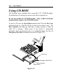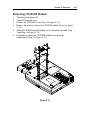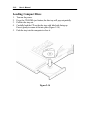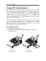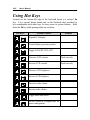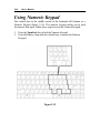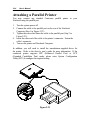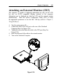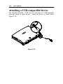
1
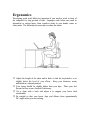
Notice
The manufacturer reserves the right to make any updates, revisions or
changes to the information contained herein as and when deemed
necessary.
The manufacturer is under no obligation to notify any
purchaser or end-user of such actions in advance or afterwards.
1998
Trademarks
IBM PC, OS/2, PS/2, EGA, and VGA are registered trademarks of
International Business Machines Corporation.
Intel, Pentium are trademarks of Intel Corporation.
MS-DOS, Microsoft Windows, Windows NT and Microsoft Mouse are
registered trademarks of Microsoft Corporation.
Sound Blaster Pro is a trademark of Creative Labs, Inc.
SystemSoft is a registered trademark of SystemSoft Corp.
Other brand and product names are trademarks of their respective
companies.
FCC Notice
This equipment has been tested and found to comply with the limits for a
Class B digital device, pursuant to Part 15 of the FCC Rules. These limits
are designed to provide reasonable protection against harmful interference
in a residential installation. This equipment generates, uses, and can
radiate radio frequency energy and, if not installed and used in accordance
with the instructions, may cause harmful interference to radio
communications. However, there is no guarantee that interference will not
occur in a particular installation. If this equipment does cause harmful
interference to radio or television reception, which can be determined by
turning the equipment off and on, the user is encouraged to try to correct
the interference by one or more of the following measures:
•
•
•
•
Reorient or relocate the receiving antenna.
Increase the separation between the equipment and receiver.
Connect the equipment into an outlet on a circuit different from that to
which the receiver is connected.
Consult the dealer or an experienced radio/TV technician for help.
CE – Certificate
This equipment is in compliance with the requirements of the following
regulation:
EN 55 022: CLASS B
Warranty Provisions
Keep the product’s bar code legible to protect your right for warranty
services.
The manufacturer warrants this personal computer to be in working order
for a period of one year from the date of shipment. If this product fails
within the one year warranty period the manufacturer will, at its option,
repair or replace the product at no charge except as set forth below.
Warranty service will be furnished on an exchange basis.
The
manufacturer may repair or replace your product with a new or
reconditioned one.
Any replaced components or parts become the
property of the manufacturer.
No warranty is expressed or implied for products damaged by accident,
abuse, misuse, acts of god, or un-authorized modification. No warranties
apply after the one year warranty period.
To obtain warranty service described herein, deliver the product along
with proof of purchase date, to any of the manufacturer’s authorized
distributors during the warranty period. The owner agrees to insure the
product and assume the risk of damage or loss in transit, to pay in advance
all shipping charges, and to use the original shipping container (or the
equivalent).
The manufacturer is not liable to any purchaser or end-user for any
damages including, but not limited to, lost revenue, lost wages, lost
savings, or any other incidental or consequential damages arising from the
purchase, use, or inability to use this product.
Important Safety Instructions
Please read and follow these important instructions.
1.
Follow all warnings and instructions marked on this product.
2.
Unplug this product from the wall outlet before cleaning it or
connecting peripheral devices.
3.
Use a damp cloth with mild soap to clean this product. Do not apply
cleaner directly to the unit. Do not use volatile or abrasive cleaners
on this product.
4.
Do not place this product on an unstable surface where it may fall.
5.
Do not block or cover the system’s ventilation openings. Also, never
place this product near or over a radiator or heat register, or in a builtin installation unless adequate ventilation is provided.
6.
Operate this product in accordance with its rated power specifications.
If you are unsure of your local power specifications, consult your
dealer or local power company.
7.
This product is equipped with a 3-wire grounding type plug. This is
an important safety feature; do not defeat its purpose. If you do not
have access to such power, have a qualified electrician install a proper
outlet.
8.
Do not allow anything to rest on the power cord. Do not locate this
product where persons will likely walk on the cord.
9.
If an extension cord is used with this product, make sure the total
current drawn by the products plugged into the extension cord do not
exceed the extension cord or outlet power ratings.
10. Do not allow foreign matter to enter the system.
11. Do not attempt to service this product yourself. Opening or removing
covers may expose dangerous voltage points. Refer all repair work to
qualified service personnel.
12. Unplug this product from the wall outlet, do not operate it, and
immediately seek proper servicing if:
•
•
•
•
•
The power cord or plug is damaged or frayed.
Liquid or foreign matter has entered this product.
This product has been exposed to rain or water.
This product has been dropped or damaged.
This product exhibits a distinct change in performance,
indicating a need for service.
13. Do not use any battery pack other than the one specifically designed
for this system. Batteries may explode or leak if exposed to fire or
improperly handled or guarded. Refer battery replacement to your
dealer or qualified service personnel.
14. Only use UL listed/CSA certified, type SVT/SJT power cords rated 6A
250V minimum (VDE approved or equivalent). It should be a
detachable type with a minimum length of 6 feet.
15. Adjust only those controls that are covered by these operating
instructions. Improper adjustment of other controls may result in
serious damage to the system and are not covered by the warranty.
Conventions
This manual uses the following conventions to describe, identify, and
highlight terms and operating procedures.
Text Conventions
Text in boldface contains messages that are important for safe operation.
Please read.
Characters in boldface represent specific items or keys, e.g. CardBus, Fn
key.
File names are presented in bold capitals, e.g. A:\>0VMAKFIL /Pn.
Abbreviations
For the purpose of clarity, abbreviations are enclosed in parentheses
following their definition; for example, Enhanced Parallel Port (EPP)
mode.
Icons
Icons identify ports and jacks of the Notebook computer.
status indicators are also identified with their relative icons.
The system
Keys
Keys appear in boldface. A plus sign (+) between two keys indicates that
they should be pressed simultaneously.
Messages
Note: A note is an advice that helps you make best use of your
Notebook computer. Please read.
Ergonomics
Developing good work habits are important if you need to work in front of
the computer for long periods of time. Improper work habits can result in
discomfort or serious injury from repetitive strain to your hands, wrists or
other joints. The following are some tips to reduce the strain:
¦ Adjust the height of the chair and/or desk so that the keyboard is at or
slightly below the level of your elbow. Keep your forearms, wrists,
and hands in a relaxed position.
¦ Your knees should be slightly higher than your hips. Place your feet
flat on the floor or on a footrest if necessary.
¦ Use a chair with a back and adjust it to support your lower back
comfortably.
¦ Sit straight so that your knees, hips and elbows form approximately
90° angles when you are working.
Lighting
Proper lighting and comfortable display viewing angle can reduce eye
strain and muscle fatigue in your neck and shoulders.
¦ Position the display to avoid glare or reflections from overhead
lighting or outside sources of light.
¦ Keep the display screen clean and set the brightness and contrast to
levels that allow you to see the screen clearly.
¦ Position the display directly in front of you at a comfortable viewing
distance.
¦ Adjust the display viewing angle to find the best position.
In addition, continuous concentration on computing work can result in
discomfort and injury. Remember to:
¦ Alter your posture frequently.
¦ Stretch and exercise your body several times a day.
¦ Take periodic breaks when you work at the computer for long periods
of time. Frequent and short breaks are of greater benefit than fewer
and longer breaks.
Table of Contents
Chapter 1: Getting Started
Unpacking ..................................................................................... 1-2
Operating Environment................................................................... 1-3
Quick Start-up............................................................................... 1-4
Powering the System............................................................. 1-4
AC Power Adapter...................................................... 1-4
Battery Pack................................................................ 1-5
Inserting.............................................................. 1-5
Removing............................................................ 1-5
Recharging by AC Power.................................... 1-6
Proper Handling of the Battery Pack.................... 1-6
Opening the LCD Cover....................................................... 1-7
LED Indicators on the LCD Cover........................................ 1-8
Top-Front View............................................................................. 1-9
LCD Panel............................................................................ 1-9
Stereo Speakers ................................................................... 1-9
Trackpad and Buttons........................................................... 1-9
Keyboard ............................................................................. 1-9
Microphone .......................................................................... 1-9
System Status LED Indicators............................................... 1-10
Power Button........................................................................ 1-10
Rear View ..................................................................................... 1-12
Headphone Jack ................................................................... 1-12
Microphone-in Jack.............................................................. 1-12
Security Connector ............................................................... 1-12
PS/2 Type Port..................................................................... 1-12
Serial Port............................................................................. 1-12
Parallel Port.......................................................................... 1-12
External Monitor (CRT) Port................................................. 1-12
USB Port.............................................................................. 1-12
Right-side View ............................................................................. 1-14
3.5” Floppy Diskette Drive ................................................... 1-14
5.25” CD-ROM Drive.......................................................... 1-14
PC Card Sockets.................................................................. 1-14
Right-side Stands .................................................................. 1-14
Left-side View............................................................................... 1-16
DC-in Socket ....................................................................... 1-16
Ventilation............................................................................. 1-16
Left-side Stands.................................................................... 1-16
Bottom View ................................................................................. 1-17
2.5” Hard Disk Drive............................................................ 1-17
CPU Cover .......................................................................... 1-17
Battery Pack......................................................................... 1-17
CD-ROM Cover .................................................................. 1-17
Chapter 2: Operation
Upgrading CPU............................................................................. 2-2
Replacing CPU..................................................................... 2-2
Setting DIP Switch......................................................................... 2-4
Accessing the 10-Pole DIP Switch........................................ 2-4
CPU Core Frequency Settings ...................................... 2-5
Flash ROM BIOS Settings ........................................... 2-5
Accessing the 8-Pole DIP Switch.......................................... 2-6
CPU Core Voltage Settings .......................................... 2-6
Accessing the 2-Pole DIP Switch.......................................... 2-7
CPU I/O Voltage Settings............................................. 2-7
Expanding Memory........................................................................ 2-8
Accessing the Memory Sockets............................................. 2-9
Installing Memory Module ............................................ 2-10
Removing Memory Module .......................................... 2-11
Using Hard Disk Drive ................................................................... 2-12
Removing.............................................................................. 2-12
Inserting................................................................................ 2-12
Replacing Hard Disk Drive.................................................... 2-13
Using Floppy Disk Drive ................................................................ 2-14
Inserting/Removing Diskettes................................................. 2-14
Write-Protecting Diskettes .................................................... 2-15
Do’s and Don’ts ................................................................... 2-15
Using CD-ROM............................................................................ 2-16
Removing CD-ROM Module................................................ 2-17
Loading Compact Discs........................................................ 2-18
Handling of Compact Discs................................................... 2-19
Using PC Card Sockets ................................................................. 2-20
Inserting PC Cards................................................................ 2-20
Removing PC Cards ............................................................. 2-21
Using Hot Keys ............................................................................. 2-22
Using Numeric Keypad.................................................................. 2-24
Windows 95 Special Keys ............................................................. 2-25
Application Key.................................................................... 2-25
Windows Key....................................................................... 2-25
LCD Panel..................................................................................... 2-26
Using Power Management.............................................................. 2-27
Advanced Power Management (APM 1.2)............................ 2-27
Advanced Configuration and Power Interface (ACPI)............ 2-27
Hard Disk Standby ............................................................... 2-28
Global Standby..................................................................... 2-28
Suspend and Resume ............................................................ 2-28
Powered On Suspend (POS) ....................................... 2-29
Resume from POS Mode ................................. 2-29
Suspend To RAM (STR) ............................................. 2-29
Resume from STR Mode ................................. 2-29
Suspend To Disk (STD)............................................... 2-30
Resume from STD Mode.................................. 2-30
Attaching Peripheral Devices.......................................................... 2-31
Attaching a Security Lock ..................................................... 2-31
Attaching a PS/2 Keyboard or Mouse................................... 2-32
Attaching a Serial Mouse....................................................... 2-33
Attaching a Parallel Printer..................................................... 2-34
Attaching an External Monitor (CRT) .................................... 2-35
Attaching a USB-compatible Device...................................... 2-36
Chapter 3: BIOS Utilities
Power On Self Test (POST) .......................................................... 3-2
POST Message: Normal Operation....................................... 3-2
POST Message: Error Detected............................................ 3-3
System Configuration Utility............................................................ 3-4
Information in the System Configuration Utility....................... 3-4
Initiating the System Configuration Utility................................ 3-5
Working with the Menu Bar of the SCU........................ 3-6
Working with the Pull-down Menu of the SCU.............. 3-7
Features of the System Configuration Utility........................... 3-8
Startup Menu............................................................... 3-8
Memory Menu............................................................. 3-10
Disks Menu ................................................................. 3-11
Components Menu....................................................... 3-12
Power Menu................................................................ 3-15
Exit Menu.................................................................... 3-18
Appendix A: Specifications .................................................................. A-1
Appendix B: I/O Port Pin Assignments ............................................... B-1
Index
Chapter 1: Getting Started
1-1
Chapter 1: Getting Started
This chapter provides a short introduction and tutorial that will familiarize
you with the Notebook system and get you up and running quickly. This
Chapter will discuss:
:
:
:
:
:
:
:
:
Unpacking
Operating Environment
Powering the System by AC Power Adapter
Powering the System by Battery Pack
Charging the Battery Pack
Opening the LCD Cover
Identifying all Devices and Ports
Identifying all LED Indicators
1-2
User’s Manual
Unpacking
Carefully unpack the Notebook Computer and the included accessories
(Figure 1-1). If there is any discrepancy or problem, contact your dealer
immediately. Be sure to save the packing materials in the event that the
notebook needs to be shipped at some point in the future.
m
m
m
m
m
m
m
m
m
Notebook Computer.
Carrying Bag.
Power Adapter.
Power Cord.
User Manual.
PS/2 Transfer Cable.
Battery Pack.
Utilities Diskettes.
CD for drivers.
Figure 1-1
Chapter 1: Getting Started
1-3
Operating Environment
As with any other precision electronic equipment, proper care and
operation of your Notebook will provide long and reliable service. Be
sure the computer system is not:
m
m
m
m
Exposed to excessive heat or direct sunlight.
Subjected to shock or vibration.
Exposed to strong magnetic fields.
Left in a place where foreign matter or moisture may enter the
system.
Figure 1-2
1-4
User’s Manual
Quick Start-up
Powering the System
AC Power Adapter
Use only the power adapter that comes with your Notebook Computer.
System operation with an incorrect power adapter will cause damage to
the Notebook and its components.
1.
2.
3.
4.
Plug the power adapter to the DC-in socket on the left panel of the
Notebook.
Connect the power cord to the power adapter.
Plug the AC power cord into a properly grounded outlet (Figure 1-3).
Refer to Chapter 1, System Status LED Indicators for more
information on system power status.
Figure 1-3
Chapter 1: Getting Started
1-5
Battery Pack
Power for continuous portable operation of the Notebook is provided by a
battery pack. When using the battery no external power source is
required. However, the actual operating time will be determined by the
application used and the configuration set.
Inserting
1. Turn the Notebook over.
2. Position the battery pack and firmly fit it into the Notebook (Figure 14).
3. The two latches will click into place when it is seated.
Removing
1. Turn the Notebook over.
2. Press the two latches in the direction indicated to release the battery
pack. (Figure 1-5)
3. Carefully lift the battery pack from the Notebook.
Figure 1-4
Figure 1-5
1-6
User’s Manual
Recharging by AC Power
The system’s battery pack will recharge whenever the system is plugged
into the AC power supply, regardless of whether the system is being
operated or not. Please refer to Chapter 1, System Status LED Indicators
for more information concerning battery charge status.
Off-Line Charge
The Notebook system is powered off. Connect
the AC adapter to the unit. Its DC output will be
used solely to charge the battery. It will take
hours to bring a completely discharged battery
to its full charge state.
Trickle Charge
The Notebook system is powered on. Again,
make sure the AC adapter is connected to the
unit. Its DC output will both power the system
and charge the battery. It may take more hours
than off-line charge to charge the battery.
Proper Handling of the Battery Pack
•
Do not attempt to disassemble the battery under any circumstances.
•
The battery may explode if exposed to fire or high temperatures.
•
Avoid short circuiting the battery by preventing contact between the
metal terminals (+, −).
Chapter 1: Getting Started
Opening the LCD Cover
1.
2.
3.
4.
To release the top cover slide the latch to the right (Figure 1-6).
Lift the top cover to reveal the LCD panel and keyboard (Figure 1-7).
Adjust the LCD panel to a comfortable viewing angle.
Press the power button to turn the system on or off (refer to Chapter
1, Top-Front View for the information of the power button).
Figure 1-6
Figure 1-7
1-7
1-8
User’s Manual
LED Indicators on the LCD Cover
Icon
Color
Green
Red
Description
Battery power is used with system turned on.
AC power is used with system turned on.
Green
Battery is fully charged.
Red
Battery is being charged.
Blinking Red
Battery power is critically low.
Figure 1-8
Chapter 1: Getting Started
1-9
Top-Front View
LCD Panel
The Notebook provides you with a large LCD panel. Depending
upon the model you have purchased, it can either be a 14.1”/13.3”
XGA (1024x768 pixels) compatible, using TFT technology, or a
12.1” SVGA (800x600 pixels) compatible, using DSTN or TFT
technology. The LCD panel is driven by a PCI local bus video
controller with 4MB video memory.
Stereo Speakers
Two built-in speakers provide clear stereo sound.
Trackpad and Buttons
The pointing device features a sensitive glide pad for precise
movements. It functions like a two-button mouse does. The right
trackpad button is equivalent to the right mouse button; the left
trackpad button is equivalent to the left mouse button.
Keyboard
The Notebook utilizes a Windows 95 keyboard that is integrated
with the numeric keypad. It is detachable for various language
versions. You may refer to Chapter 2: Operation for more
information.
Microphone
This is the built-in microphone for recording sound into your
applications.
1-10
User’s Manual
System Status LED Indicators
The LED indicators display the system’s operation status.
Icon
Color
Green
Red
Description
Battery power is used with system turned on.
AC power is used with system turned on.
Green
Battery is fully charged.
Red
Battery is being charged.
Blinking Red
Battery power is critically low.
Green
The hard disk is being accessed.
Green
The system has entered Suspend-To-RAM
(STR) or Power-On-Suspend (POS) mode.
Power Button
Icon
Description
Use this button to turn the system on or off.
Note: After turning off the system, wait for a few seconds to power it on
again when you need to.
Chapter 1: Getting Started
LCD Panel
Stereo Speakers
Power Button
Keyboard
Microphone
Trackpad & Buttons
Figure 1-9
Figure 1-10
1-11
1-12
User’s Manual
Rear View
Microphone-in Jack
Use this jack to connect a microphone to the system for audio input.
Headphone Jack
Headphone can be attached to the system through this jack for audio
output, so can external speakers that have built-in output power
amplifier.
Security Connector
The Security Connector is used to protect your Notebook from being
stolen. Wrap the steel cable around your desk. Next, insert the
locking device into this security connector.
PS/2 Type Port
A PS/2 type mouse and keyboard may be connected to the system
using this port.
Serial Port
This port is UART 16C550 compatible. It features a 9-pin
connector for the addition of an external mouse for example.
Parallel Port
This parallel port supports EPP (Enhanced Parallel Port) and ECP
(Extended Capabilities Port) modes.
External Monitor (CRT) Port
This port is used for transmission of the display to an external
monitor. Simultaneous display with the LCD panel is available.
USB Port
The Universal Serial Bus (USB) port simplifies the expansion
capability for peripherals by daisy-chain connection of a number of
USB-equipped devices.
Chapter 1: Getting Started
Microphone-in jack
1-13
Headphone jack
Serial port
PS/2 type port
Security connector
Parallel port
CRT port
Figure 1-11
USB port
1-14
User’s Manual
Right-side View
3.5” Floppy Diskette Drive
The Notebook comes standard with a 1.44MB floppy drive installed.
Press the button on its top-right side to eject the diskette.
5.25” CD-ROM Drive
The 5.25” IDE CD-ROM module is designed to be changeable
installing or removing the two screws that fasten the CD-ROM
drive. The eject button is located in the middle of the front cover of
the CD-ROM drive. Pressing it will release the CD tray. Refer to
Chapter 2: Operation, for more information.
PC Card Sockets
One Type III or two Type II PC cards may be used. Both sockets
will expand the system capabilities when a PC card is inserted. To
eject the PC card, press the appropriate eject button (Figure 2-17).
Infrared
The system adopts infrared technology as the interface for simple,
fast and convenient data exchange from the Notebook to an infraredcompatible device. It implements IrDA (HPSIR) and Amplitude
Shifted Keyed IR (ASKIR). No object should be blocking the line
of sight between the Notebook and the infrared-equipped device.
For further information, refer to the manual of the wireless device
you wish to connect on how to use the point-and-shoot operation.
Right-side Stands
When a high speed CPU is installed, the erecting stands on both
sides will help heat dissipation during operation.
Chapter 1: Getting Started
3.5” Floppy Disk Drive
Infrared
5.25” CD-ROM
PC Card Sockets
Right-side Stands
Figure 1-12
1-15
1-16
User’s Manual
Left-side View
DC-in Socket
Plug the AC adapter into this socket for power supply.
disconnect, pull the plug (not the cord) directly back.
To
Ventilation
The Notebook provides ventilation to dissipate the system’s
operating heat. Do not block or obstruct it during operation.
Left-side Stands
When a high speed CPU is installed, the erecting stands on both
sides will help heat dissipation during operation.
DC-in Socket
Ventilation
Left-side Stands
Figure 1-13
Chapter 1: Getting Started
1-17
Bottom View
2.5” Hard Disk Drive
The 2.5” hard disk drive accepts any 2.5” IDE hard disk drive with
a height of 12.7mm or less. Accessing the corresponding screws
will allow you to install or to remove this hard disk drive. Refer to
Chapter 2: Operation, for more information.
CPU Cover
Detaching the screws to remove the cover will reveal the
microprocessor. You may upgrade the CPU for higher system
performance.
Battery Pack
This compartment houses a rechargeable battery pack of either NiMH or Li-Ion. To recall detailed information turn back to the
section Battery Pack.
CD-ROM Cover
The CD-ROM cover functions for easy installation and easy
removal of the CD-ROM, in case you need maintenance service
during warranty period.
1-18
User’s Manual
2.5” Hard Disk Drive
CPU Cover
CD-ROM Cover
Battery Pack
Figure 1-14
Chapter 2: Operation
2-1
Chapter 2: Operation
The Notebook has many advanced features to help you with your
computing work. This chapter describes each of the Notebook’s hardware
features and shows you how to use them.
Before you begin working with any internal components of the
Notebook, remove the battery and disconnect the AC power adapter.
Make sure that you wear an anti-static wrist strap to ground yourself
before working with any internal components of the Notebook. Static
electricity may damage components beyond repair.
:
:
:
:
:
:
:
:
:
:
:
:
Upgrading CPU
Setting DIP Switches
Expanding Memory
Using Hard Disk Drive
Using Floppy Disk Drive
Using CD-ROM
Using PC Card Sockets
Using Hot Keys
Using Numeric Keypad
Getting Familiar with LCD Panel
Using Power Management
Attaching Peripheral Devices
2-2
User’s Manual
Upgrading CPU
The system is capable of hosting a wide range of Intel Pentium and AMD
K6 processors. Upgrading your CPU will increase your computing speed.
The higher the CPU speed installed, the better the system performance.
Different CPUs may have different power voltages. If you want to
upgrade the CPU, remember to adjust the corresponding settings.
Replacing CPU
1.
2.
3.
4.
Remove all power sources (AC power and battery).
Turn the Notebook over.
Remove the CPU cover.
Remove the screws that fasten the heat sink mounted on the CPU
(Figure 2-1).
Figure 2-1
Note:
• Contact your dealer for the proprietary tool to replace the CPU.
• Wait for the CPU to cool down before replacing it.
Chapter 2: Operation
2-3
Replacing the Hex Studs
You need to install the correct four hex studs to properly accommodate the
height of the CPU just installed.
CPU
Intel Pentium Processor at 3.3V I/O Voltage
Intel Pentium Processor at 2.5V I/O Voltage
AMD K6 Processor
Color of Hex Studs
Black
Silver
Bronze
Reinstallation
Reinstall the CPU in the reverse order of removal. Make sure that the heat
sink cable is properly installed.
2-4
User’s Manual
Setting DIP Switch
You need to set the following DIP Switches for correct system
configuration:
•
10-pole DIP Switch for CPU core frequency (MHz) and flash
ROM BIOS.
•
8-pole DIP Switch for CPU core voltage.
•
2-pole DIP Switch for CPU I/O voltage.
Accessing the 10-Pole DIP Switch
1.
2.
3.
Turn the system power off.
Press the two keyboard latches so that the keyboard can be elevated
from its normal position (Figure 2-2).
Carefully lift the keyboard assembly out so that the mainboard is
exposed. Employ the 10-pole DIP Switch to set the configuration
(Figure 2-3).
Figure 2-2
Figure 2-3
Chapter 2: Operation
2-5
CPU Core Frequency Settings
The correct configuration for CPU core frequency is listed as follows:
Intel Pentium Processor at 3.3V I/O Voltage
CPU Frequency
1
2
3
4
5
6
7
8
120 MHz
133 MHz
150 MHz
166 MHz
200 MHz
233 MHz
X
X
X
X
X
X
X
X
X
X
X
X
X
X
X
X
X
X
On
Off
On
Off
Off
Off
Off
Off
Off
Off
Off
Off
On
On
On
On
Off
Off
Off
Off
On
On
On
Off
Off
Off
Off
Off
Off
Off
9
10
Off
Off
Off
Off
Off
Off
Off
Off
Off
Off
Off
Off
9
10
Off
Off
Off
On
On
On
* X = Not Applied.
Intel Pentium Processor at 2.5V I/O Voltage
CPU Frequency
1
2
3
4
5
6
7
8
200 MHz
233 MHz
266 MHz
X
X
X
X
X
X
X
X
X
Off
Off
Off
Off
Off
Off
Off
Off
On
CPU Frequency
1
AMD K6 Processor
2
3
4
5
6
266 MHz
300 MHz
X
X
X
X
On
Off
On
On
On
Off
* X = Not Applied.
X
X
Off
Off
Off
Off
On
On
7
8
9
10
Off
On
On
On
Off
Off
Off
Off
* X = Not Applied.
Flash ROM BIOS Settings
In order to keep up with the latest system BIOS, your Notebook may be
upgraded. Consult your dealer for further information. The DIP Switch
needed to be set in the On position when updating the existing system
BIOS. The DIP Switches should be reset to the Off position after BIOS
updating is complete.
Flash ROM BIOS
1
2
3
4
5
6
7
8
9
10
Existing BIOS
Updating BIOS
Off
On
Off
On
X
X
X
X
X
X
X
X
X
X
X
X
X
X
X
X
* X = Not Applied.
2-6
User’s Manual
Accessing the 8-Pole DIP Switch
Access the 8-pole DIP Switch to set the CPU core voltage.
1. Turn the system power off.
2. Turn the Notebook over.
3. Remove the CPU cover. Use the 8-pole DIP Switch to set the
configuration (Figure 2-4).
Figure 2-4
CPU Core Voltage Settings
The correct configuration for CPU core voltage is listed as follows:
CPU Core Voltage
1.8 V
2.0 V
2.2 V
2.45 V
2.8 V
3.45 V
* X = Not Applied.
1
On
On
On
On
On
On
2
Off
On
On
On
On
On
3
Off
Off
On
On
On
On
4
Off
Off
Off
On
On
On
5
Off
Off
Off
Off
On
On
6
Off
Off
Off
Off
Off
On
7
X
X
X
X
X
X
8
X
X
X
X
X
X
Chapter 2: Operation
2-7
Accessing the 2-Pole DIP Switch
Access the 2-pole DIP Switch to set the CPU I/O voltage.
1. Turn the system power off.
2. Turn the Notebook over.
3. Remove the CPU cover. Use the 2-pole DIP Switch to set the
configuration (Figure 2-5).
Figure 2-5
CPU I/O Voltage Settings
The correct configuration for CPU I/O voltage is listed as follows:
CPU I/O Voltage
2.5 V
3.45 V
1
On
On
2
Off
On
If what you install is Intel Pentium processor at 3.3V I/O voltage, please
set the same as 3.45V.
2-8
User’s Manual
Expanding Memory
The system has two memory sockets for different RAM modules to
expand the memory up to 128MB. These RAM modules are of a 144-pin
SODIMM (Small Outline Dual In-line Memory Module) type. The
Notebook supports Fast Page Mode, EDO (Extended Data Out), and
SDRAM operation. With the following memory configurations the total
memory size will be automatically detected by the POST routines:
Bank 1
(64-bit)
(1Mx16)x4
(1Mx16)x4
(1Mx16)x8
(1Mx16)x8
(4Mx16)x4
(1Mx16)x8
(4Mx16)x4
(4Mx16)x8
(8Mx8)x8
(4Mx16)x8
(4Mx16)x8
(4Mx16)x8
(4Mx16)x8
(8Mx8)x8
Bank 2
(64-bit)
None
(1Mx16)x4
None
(1Mx16)x4
None
(1Mx16)x8
(4Mx16)x4
None
None
(1Mx16)x4
(1Mx16)x8
(4Mx16)x4
(4Mx16)x8
(8Mx8)x8
Power
Minimum
Speed
FPG: 60ns
3.3V
EDO: 60ns
SDRAM:75MHz
Total Size
8MB
16MB
16MB
24MB
32MB
32MB
64MB
64MB
64MB
72MB
80MB
96MB
128MB
128MB
Chapter 2: Operation
Accessing the Memory Sockets
1.
2.
3.
Turn the system power off.
Press the two keyboard latches so that the keyboard can be elevated
from its normal position (Figure 2-2).
Carefully lift the keyboard assembly out so that the mainboard is
exposed. Locate the memory sockets (Figure 2-6).
Bank 2
Bank 1
Figure 2-6
2-9
2-10
User’s Manual
Installing Memory Module
Follow the steps below to install the memory module:
1.
2.
3.
4.
5.
Turn the system power off.
Press the two keyboard latches so that the keyboard can be elevated
from its normal position (Figure 2-2).
Carefully lift the keyboard assembly out so that the mainboard is
exposed. Locate the memory sockets (Figure 2-6).
Position the memory module at a slight angle and fit its connectors
into the socket firmly. Push the module down and ensure it locks into
place (Figure 2-7).
Reinstall the keyboard assembly.
Figure 2-7
Chapter 2: Operation
Removing Memory Module
1.
2.
3.
4.
5.
6.
Turn the system power off.
Press the two keyboard latches so that the keyboard can be elevated
from its normal position (Figure 2-2).
Carefully lift the keyboard assembly out to expose the mainboard.
Locate the memory sockets (Figure 2-6).
Gently pull the two latches on both ends of the module outward. The
module will pop up (Figure 2-8).
Remove the memory module.
Reinstall the keyboard assembly.
Figure 2-8
2-11
2-12
User’s Manual
Using Hard Disk Drive
The hard disk drive is mounted in a removable case and may therefore be
taken out to accommodate other 2.5” IDE hard disk drives with a height of
12.7mm. The system supports drives with capacities greater than 528MB
through the Logical Block Addressing (LBA) mode. It also supports
Programmed I/O (PIO) mode 4 and provides a high performance data
transfer rate at speeds up to 33 MBytes/second (ATA-33).
Removing
1.
2.
3.
4.
5.
Turn the system power off.
Turn the Notebook over.
Remove the HDD cover (Figure 2-9).
Disconnect the cable (Figure 2-9).
Detach the HDD case from the Notebook (Figure 2-9).
HDD Cover
Cable
HDD Case
Figure 2-9
Inserting
Reinstall the Hard Disk Drive in the reverse order of removal.
Chapter 2: Operation
2-13
Replacing Hard Disk Drive
The hard disk drive is contained within a case. Two screws on each side
of the case need to be removed so that the hard disk drive can be taken out
of the case to replace with another one (Figure 2-10). The location of the
two screws may be varied depending on different hard disk models.
Gently disconnect the cable from the hard disk drive when taking it out of
the case. Be careful not to bend any pins or crimp the cable.
Figure 2-10
2-14
User’s Manual
Using Floppy Disk Drive
The Notebook comes standard with a 1.44MB, 3.5” floppy disk drive. It
is labeled drive A: and may be used as a boot device if properly set.
Inserting/Removing Diskettes
When using the floppy drive, always insert your floppy diskette label-side
up (Figure 2-11). To remove your diskette, press the eject button on the
top-right corner of the floppy drive.
Figure 2-11
Chapter 2: Operation
2-15
Write-Protecting Diskettes
Diskettes can be write-protected to prevent files from being accidentally
erased or destroyed. To write-protect a 3.5” floppy diskette, move the
built-in write-protect tab to the write-protect position, (“up” so that you
can see through the “hole” in the upper, right-hand corner of the diskeet).
Putting the write protect tab back “down” will enable you to write data on
the disk again.
Do’s and Don’ts
• Always make backup copies of your software and data diskettes.
• Keep diskettes away from magnetic fields.
• Do not remove diskettes from the drive while the diskette “in-use”
•
•
•
•
light in on.
Do not open or remove the protective shutter which covers the
diskette’s media.
Do not allow dust or moisture to collect on diskettes.
Do not bend or throw diskettes.
Do not clean diskettes with liquids or solvents.
2-16
User’s Manual
Using CD-ROM
The Notebook comes standard with a removable 5.25” CD-ROM module.
It is labeled drive D: and may be used as a boot device if properly set.
Do not disassemble the CD-ROM module. Only certified technicians
should perform repairs to the CD-ROM module.
To insert a CD, press the Eject Button and place the CD on the Disc Tray
label-side facing up. Push the CD tray in and you are ready to start. The
Busy Indicator will light up while data is being accessed or while an
audio CD is playing.
When power to the system is unexpectedly
interrupted, insert an instrument such as a straightened paper clip into the
Emergency Eject Hole to manually eject the tray (Figure 2-12).
Disc Tray
Emergency Eject Hole
Busy Indicator
Eject Button
Figure 2-12
Chapter 2: Operation
Removing CD-ROM Module
1.
2.
3.
4.
5.
6.
Turn the system power off.
Turn the Notebook over.
Remove the CD-ROM cover (Step 1 in Figure 2-13).
Remove the screw to release the CD-ROM module. (Step 2 in Figure
2-13).
Slide the CD-ROM module slightly out to disconnect the cable (Step
3 and Step 4 in Figure 2-13).
Pull gently and firmly the CD-ROM module away from the
compartment (Step 5 in Figure 2-13).
Figure 2-13
2-17
2-18
User’s Manual
Loading Compact Discs
1.
2.
3.
4.
5.
Turn on the power.
Press the CD-ROM eject button; the disc tray will pop out partially.
Pull the disc tray out.
Carefully load the CD on the disc tray with label-side facing up.
Press it gently to ensure it fits into place (Figure 2-14).
Push the tray into the computer to close it.
Figure 2-14
Chapter 2: Operation
2-19
Handling of Compact Discs
Proper handling of your CDs will prevent them from being damaged and
ensure the accessibility of data stored on them.
•
Hold the CD by the edges; do not touch the surface of the disc.
•
Use clean, soft, dry cloth to remove dust or fingerprints.
•
Do not write on the surface using pen.
•
Do not attach any paper or other materials to the surface of the disk.
•
Do not store or place the CD in areas where it will be exposed to high
temperatures.
•
Do not use benzine, thinners, or other cleaners to clean the CD.
•
Do not bend the Compact Disc.
•
Do not drop or subject the CDs to shock.
2-20
User’s Manual
Using PC Card Sockets
The Notebook provides system expansion capabilities with two PC card
sockets (previously referred to as PCMCIA). PC cards to be inserted can
be LAN, fax/modem, communication devices, or expanded memory. Both
sockets support 3.3V 32-bit PC cards, referred to as CardBus. The
CardBus sockets are backward compatible with 5V 16-bit PC cards.
There are three types of PC cards. Type I measures 3.3mm thick; Type II
5.0mm; and Type III 10.5mm.
The PC card sockets accommodate one Type III card or two Type II cards
and the lower socket named Socket A is capable of ZV (Zoomed
Video), which allows a direct connection between a PC card and video
devices that enables high quality video playback.
Inserting PC Cards
1.
2.
Open the access door (Figure 2-15).
Align the PC card with the slot and push it in firmly until it locks into
place (Figure 2-16).
Figure 2-15
Figure 2-16
Chapter 2: Operation
2-21
Removing PC Cards
To remove a PC card, press the appropriate eject button and the card will
be ejected from its slot (please refer to Figure 2-17).
Eject button for socket B
Socket B
Socket A
Eject button for socket A
Figure 2-17
2-22
User’s Manual
Using Hot Keys
Located on the bottom-left edge of the keyboard layout is a colored Fn
key. It is a special feature found only on the Notebook that provides for
key combinations with other keys for easy access to system features. Hold
down the Fn key while pressing other key as below:
Hot Keys
System Features
Remark
Expand LCD display
+
Control display top/center position
+
Toggle LCD/CRT/LCD+CRT
+
Decrease LCD contrast
Dual scan only
Increase LCD contrast
Dual scan only
+
+
Decrease LCD brightness
+
Increase LCD brightness
+
Decrease audio volume
+
Increase audio volume
+
Toggle audio mute on/off
+
+
Put the system in a suspend state for
power management
Chapter 2: Operation
Figure 2-18
2-23
2-24
User’s Manual
Using Numeric Keypad
The colored keys in the middle section of the keyboard will function as a
Numeric Keypad (Figure 2-19). The numeric keypad overlay can be used
for numeric data input. Follow these steps to access the Numeric Keypad:
1.
2.
Press the NumLock key to lock the Numeric Keypad.
Press the Fn key along with the colored keys to operate the Numeric
Keypad.
Figure 2-19
Chapter 2: Operation
2-25
Windows 95 Special Keys
Application Key
The Application key has the same function as the
secondary mouse button.
Windows Key
The Window key activates the Start menu.
2-26
User’s Manual
LCD Panel
The Notebook Computer features the LCD panel display with the
following:
•
•
•
•
•
•
•
PCI local bus controller.
4MB video RAM (SGRAM type).
Capability to support 1024x768 (XGA) resolution TFT display.
Capability to support 800x600 (SVGA) resolution DSTN/TFT
display.
Ability to transmit video signals to a VGA monitor (CRT).
Capable of simultaneous display on LCD and CRT.
Video Port Manager (VPM) for video input from ZV-capable PC
card.
Remark:
Two technologies of LCD display:
• Passive technology (DSTN = Dual-scan
Nematic).
• Active technology (TFT = Thin Film Transistor).
Super
Twisted
Chapter 2: Operation
2-27
Using Power Management
The Notebook system provides you with various modes to manage its
power consumption while maintaining system performance. Please refer
to Chapter 3: BIOS Utilities, System Configuration Utility, Power Menu
for more information.
Advanced Power Management (APM 1.2)
The Notebook provides built-in Advanced Power Management (APM 1.2)
support to reduce power consumption. APM function varies depending on
the operating system you are using. Some operating systems do not
support APM, such as Windows NT, and therefore, cannot take
advantage of the system’s capabilities in this area.
Advanced Configuration and Power
Interface (ACPI)
The ACPI interface gives the operating system (OS) direct control over
the power management and Plug and Play functions of a computer. The
operating system can perform the functions covered by the ACPI
specification, such as system power management, device power
management, and thermal management.
2-28
User’s Manual
Hard Disk Standby
The system will turn off the Notebook’s hard disk drive motor if it has not
been accessed after a specified period of time. The motor will be turned
back on once the system attempts to read or write data to it.
Global Standby
In Global Standby mode, the CPU clock will be stopped and most
controllable peripheral devices will be powered off. If the idle timer
expires before any system activity is detected, the system will change from
Standby mode into Suspend mode.
Suspend and Resume
When at extremely low power the system will halt operations yet retain all
its programming. This is called Suspend Mode. The Suspend Mode
features three levels: Powered-On-Suspend (POS) mode, Suspend-ToRAM (STR) mode, and Suspend-To-Disk (STD) mode.
Be sure not to initiate the Suspend Mode when any of the disk drives
is accessed such as HDD, FDD and CD-ROM drive.
The system operation can be returned to exactly where it was suspended
when wake-up event occur. This is called Resume .
Chapter 2: Operation
2-29
Powered On Suspend (POS)
Of the three suspend modes, Powered-On-Suspend saves the least amount
of power. However, it takes the shortest time to return to full operation.
Resume from POS Mode
The system may be resumed from Powered-On-Suspend mode by:
•
•
•
Alarm resume (month/day/hour/minute)
Modem ring
Any keyboard key pressed
Suspend To RAM (STR)
Suspend-To-RAM
management.
mode
is
the
medium
level
of
Resume from STR Mode
The system may be resumed from Suspend-To-RAM mode by:
•
•
Alarm resume (month/day/hour/minute)
Modem ring
system
power
2-30
User’s Manual
Suspend To Disk (STD)
Suspend to Disk is a 0-volt suspend mode for system power management.
STD mode saves the maximum power but takes the longest time to return
to full operation.
1.
Use your operating system’s FDISK program to delete all partitions
of the hard disk if any already exist on the target drive.
2.
Boot the system from the A: drive and run the 0VMAKFIL.EXE
Utility to create the Suspend to Disk partition on the hard disk of a
size that will accommodate the installed DRAM (n) plus 2MB
integrated video RAM.
A:\>0VMAKFIL /Pn
For example, if the system DRAM is 32MB, 0VMAKFIL will create a
partiton size of approximately 34MB.
A:\>0VMAKFIL /P32
Note:
Rewrite the sector signatures if you need to partition the
hard disk again.
C:\>0VMAKFIL /PW
3.
Re-partition the hard disk using your operating system’s FDISK
program.
Resume from STD Mode
The system may be resumed from Suspend-To-Disk mode by:
•
•
Power back on
Alarm resume (month/day/hour/minute)
Chapter 2: Operation
2-31
Attaching Peripheral Devices
The herein mentioned shows you how to attach peripheral devices to the
ports or jacks on the rear panel of the Notebook Computer.
Attaching a Security Lock
To protect your Notebook from being stolen, the computer is equipped
with a security connector. To install the security lock, wrap the cable
around a desk or other immovable object, then insert the locking device
into the connector (Figure 2-20).
Figure 2-20
2-32
User’s Manual
Attaching a PS/2 Keyboard or Mouse
The Notebook can be operated with a PS/2 keyboard or mouse attached by
means of the PS/2 transfer cable. Attach the external keyboard or mouse
as shown below (Figure 2-21).
Figure 2-21
Chapter 2: Operation
2-33
Attaching a Serial Mouse
The serial port features a 9-pin connector.
device such as a mouse to this port.
1.
2.
3.
4.
You can connect any serial
Turn the system power off.
Connect the cable to the serial port on the rear of the Notebook
Computer (Step 1 in Figure 2-22).
Tighten the screws that fasten the cable to the serial port (Step 2 in
Figure 2-22).
Turn on the Notebook Computer.
In addition, you may need to install the manufacturer-supplied driver for
the serial mouse. Refer to the device’s user’s guide for more information.
Figure 2-22
2-34
User’s Manual
Attaching a Parallel Printer
You may connect any standard Centronics parallel printer to your
Notebook using the parallel port.
1.
2.
3.
4.
5.
Turn the system power off.
Connect the cable to the parallel port on the rear of the Notebook
Computer (Step 1 in Figure 2-23).
Tighten the screws that fasten the cable to the parallel port (Step 2 in
Figure 2-23).
Insert the other end of the cable to the printer’s connector. Fasten the
cable’s connector.
Turn on the printer and Notebook Computer.
In addition, you will need to install the manufacturer-supplied driver for
the printer. Refer to the device’s user’s guide for more information. If the
connected printer supports EPP (Enhanced Parallel Port) or ECP
(Extended Capabilities Port) mode, please enter System Configuration
Utility (SCU) to configure the required setting.
Figure 2-23
Chapter 2: Operation
2-35
Attaching an External Monitor (CRT)
The computer is capable of displaying information not only on the LCD,
but also on SVGA compatible displays attached to the computer.
Information can be displayed on both the LCD and the external monitor
simultaneously. Enter the System Configuration Utility (SCU) to select
the appropriate parameters or use the Fn + F6 keys (refer to Chapter 2,
Using Hot Keys).
1.
2.
3.
4.
5.
Turn the system power off.
Connect the cable to the CRT port on the rear of the Notebook
Computer (Step 1 in Figure 2-24).
Tighten the screws that fasten the cable to the CRT port (Step 2 in
Figure 2-24).
Insert the other end of the cable to the external monitor.
Turn on the Notebook Computer.
Figure 2-24
2-36
User’s Manual
Attaching a USB-compatible Device
The Notebook provides a USB port for connection of a USB-compatible
keyboard, mouse or other devices. Attach the device as shown below
(Figure 2-25).
Figure 2-25
Chapter 3: BIOS Utilities
3-1
Chapter 3: BIOS Utilities
This chapter provides information regarding the Power On Self Test
(POST) and shows you how to configure the system parameters using the
System Configuration Utility (SCU).
: Power On Self Test (POST)
: Initiating the System Configuration Utility (SCU)
: Specifying in the System Configuration Utility (SCU)
3-2
User’s Manual
Power On Self Test (POST)
The system BIOS (Basic Input/Output System) performs a series of Power
On Self Test (POST) on system memory and key computer components
every time the computer is turned on. If an error exists, the POST routine
may halt execution (depending on the severity of the problem). The POST
also initializes BIOS configuration then boots the operating system.
POST Message: Normal Operation
If no error occurs, the system will be operating after the POST process is
completed.
You may press the Spacebar key to skip the memory test.
SystemSoft MobilePRO BIOS Version 1.01 (2482-00)
Copyright 1983-1996 SystemSoft Corp. All Rights Reserved
233 MHz Pentium with MMX CPU
External Cache: 512KB installed
2 MB Video RAM
SystemSoft Plug-n-Play BIOS Ver.1.17.01
Base Memory
Extended Memory
Total Memory
000640 Kb
064512 Kb
065536 Kb
Auto Detecting IDE Devices[Done]
<CTRL-ALT-S> to enter System Configuration Utility
Chapter 3: BIOS Utilities
3-3
POST Message: Error Detected
If an error is detected, a WARNING message will be displayed. You
should either press F1 key to continue, or press the Ctrl-Alt-S keys
simultaneously to enter the System Configuration Utility.
SystemSoft MobilePRO BIOS Version 1.01 (2482-00)
Copyright 1983-1996 SystemSoft Corp. All Rights Reserved
233 MHz Pentium with MMX CPU
External Cache: 512KB installed
2 MB Video RAM
SystemSoft Plug-n-Play BIOS Ver.1.17.01
Base Memory
Extended Memory
Total Memory
000640 Kb
064512 Kb
065536 Kb
WARNING – HARD DISK CONTROLLER 1 FAILURE
Auto Detecting IDE Devices[Done]
<CTRL-ALT-S> to enter System Configuration Utility
Press F1 to Continue
3-4
User’s Manual
System Configuration Utility
The System Configuration Utility (SCU) is a ROM-based configuration
utility that displays the system’s configuration status and provides users
with a tool to set their system parameters. The settings are stored in nonvolatile battery-backed CMOS RAM which saves the information even
when the power is turned off, and retains it when the system is turned back
on.
Information in the System Configuration Utility
The following shows the system settings that may be changed within the
System Configuration Utility.
Menu Bar Items
Startup
Memory
Disks
Components
Power
Exit
Pull-down Menu Items
Date and Time, Fast Boot, Boot Device, Display, Enable
Battery Low Beep, Enable LCD Expand Mode, Boot
Password, SCU Password.
Cache Systems.
Diskette Drives, IDE Settings.
COM Ports, LPT Port, PS/2 Mouse Port, Keyboard
Numlock, Keyboard Repeat, Enable Sound System,
Audio Device.
Enable Power Saving, Low Power Saving, Medium
Power Saving, High Power Saving, Customize, Suspend
Controls, Resume Timer, Enable MODEM Ring Resume,
Enable Battery Low Suspend, Advance CPU Controls.
Save and Exit, Exit (No Save), Default Settings, Restore
Settings, Version Info.
Chapter 3: BIOS Utilities
3-5
Initiating the System Configuration Utility
The System Configuration Utility (SCU) will
simultaneously pressing the Ctrl, Alt, and S keys.
be
accessed
when
<CTRL-ALT-S> to enter System Configuration Utility
The above message only lasts seconds. If you miss it, the computer will
initiate the boot process. You must reboot the system and try again within
the time limit if you want to enter the System Configuration Utility.
Figure 3-1
System Configuration Utility (SCU)
3-6
User’s Manual
Working with the Menu Bar of the System
Configuration Utility
Press Ctrl-Alt-S keys simultaneously to enter the menu bar of the System
Configuration Utility.
Action
Activate menus
Alt
Keys Used
Select menu bar item
Left arrow (←)
Right arrow (→)
Accept menu bar item
Cancel current action
The highlighted letter
key
Mouse left button
Spacebar
Enter
Mouse right button
Esc
Description
Activate the System
Configuration Utility.
Move to a menu bar item on
the left.
Move to a menu bar item on
the right.
Move to the corresponding
menu bar item.
Enter the selected menu bar
item to configure settings.
Undo the current command.
Chapter 3: BIOS Utilities
3-7
Working with the Pull-down Menu of the System
Configuration Utility
When the desired menu bar item is highlighted, press the Enter key to
enter the pull-down menu for values setting.
Action
Select pull-down
menu item
Keys Used
Down arrow (↓)
Up arrow (↑)
Select a control
Change values
Accept entries
The highlighted letter
key
Tab
Down/Up arrows
(↓)(↑)
Spacebar
Enter
Reject entries
Esc
Enter
Activate accelerators Alt
Quit
Esc
Description
Move to the next pull-down
menu item.
Move to the previous pulldown menu item.
Move to the corresponding
pull-down menu item.
Move between the options.
Modify the settings.
Enable/disable the specified
function. When a check
mark (√) appears, the
function is on.
Choose <OK> from a list of
options.
Undo the current setting.
Choose <Cancel> from a list
of options.
Initiate all the highlighted
letters corresponding to their
respective options.
Press the Esc key to close
the pull-down menu.
3-8
User’s Manual
Features of the System Configuration Utility
Startup Menu
Item
Setting/Option
Date and Time Day/Month/Year
Hour/Minute/Second
Fast Boot
Enable
Boot Device
Disable
1st Boot
device
2nd Boot
Device
3rd Boot
Device
Display
Hard Disk C
CD-ROM Drive
Diskette A
Hard Disk C
CD-ROM Drive
Diskette A
Hard Disk C
CD-ROM Drive
Diskette A
CRT
LCD
LCD+CRT
Enable Battery Enable
Low Beep
Enable LCD
Expand Mode
Disable
Enable
Disable
Function
Set the current date and time.
Initialize and quickly boot the
system in a few seconds by
skipping certain diagnostic
tests.
Disable the above.
Specify where the system
boots from.
Specify where the system
boots from.
Specify where the system
boots from.
Activate an external monitor.
Activate the system’s LCD
panel.
Activate both the LCD and the
CRT.
The system emits a series of
warning beeps sound when the
battery power becomes low.
Disable the above.
Stretch the display to fill the
entire viewing area of the LCD
panel.
Disable the above.
Chapter 3: BIOS Utilities
Item
Boot Password
SCU Password
Setting/Option
Enter old Power-On
Password
Enter new Power-On
Password
Verify new Power-On
Password
Enable Password to
Power-On
Enter old Setup Password
Enter new Setup
Password
Verify new Setup
Password
Enable Setup Password
3-9
Function
Set password for booting
computer. Users are authorized
to start the system after entering
correct password.
Set password for modifying
SCU. Users are authorized to
change the SCU setting after
entering correct password.
Figure 3-2
Startup Menu
3-10
User’s Manual
Memory Menu
Item
Cache
Systems
Setting/Option
L1 Cache
Disabled
Write Back
L2 Cache
BIOS Shadow
Disabled
Write Back
Cached
Video Shadow
Not Cached
Cached
Not Cached
Function
Disable the processor’s internal
cache.
Enable the processor’s internal
write-back cache.
Disable the L2 cache controller.
Enable the L2 write-back cache.
The process of shadowing copies
instructions from system BIOS
into RAM to improve system
performance.
Disable the above.
The process of shadowing copies
instructions from video BIOS into
RAM to improve system
performance.
Disable the above.
Figure 3-3
Memory Menu
Chapter 3: BIOS Utilities
3-11
Disks Menu
Item
Diskette
Drives
IDE Settings
Setting/Option
Drive A
None
1.44 MB
2.88 MB
Primary
Drive Enabled
HDD
PIO Mode
CD-ROM
Drive Enabled
PIO Mode
Figure 3-4
Disks Menu
Function
Specify the drive types for the
diskette drive A.
Enable enhanced IDE settings.
3-12
User’s Manual
Components Menu
Item
COM Ports
LPT Port
PS/2 Mouse
Port
Setting/Option
COM A I/O
None
Settings
COM1, 3F8, IRQ4
COM2, 2F8, IRQ3
COM3, 3E8,
IRQ4
COM4, 2E8,
IRQ3
Port Address
None
LPT1, Addr 378h,
IRQ7
LPT2, Addr 278h,
IRQ5
LPT3, Addr
3BCh, IRQ7
Port Definition Standard AT
(Centronics)
Bidirectional
(PS-2)
Enhanced Parallel
(EPP)
Extended
Capabilities (ECP)
DMA Setting
DMA 1
For ECP Mode DMA 3
EPP Type
EPP 1.7
EPP 1.9
Enable
Disable
Function
Specify the COM A
port, I/O address, and
IRQ signal.
Specify the LPT port,
I/O address, and IRQ
signal.
Specify the LPT port
transmission mode.
The EPP and ECP
modes work only
with EPP and ECP
aware peripheral
devices.
Specify the ECP
DMA channel.
Specify the EPP
mode version.
Enable the system’s
pointing device or an
external PS/2 mouse.
Disable the built-in
pointing device or
PS/2 mouse if an
external mouse is
connected to COM A
port.
Chapter 3: BIOS Utilities
Item
Keyboard
Numlock
Keyboard Repeat
Setting/Option
Enable
Disable
Key Repeat
Rate
Key Delay
2 cps
6 cps
10 cps
15 cps
20 cps
30 cps
¼ sec
½ sec
¾ sec
1 sec
Enable Sound
System
Audio Device
Enable
Disable
Audio Port
Addresses
FM Alias Port
Audio IRQ
Playback DMA
Record DMA
At 220h-22Fh
At 240h-24Fh
At 260h-26Fh
At 280h-28Fh
At 388h-38Bh
At 408h-40Bh
At 488h-48Bh
At 508h-50Bh
IRQ 5
IRQ 7
IRQ 9
IRQ 10
DMA 0
DMA 1
DMA 3
DMA 0
DMA 1
DMA 3
3-13
Function
Specify if Num Lock
is on or off at system
boot time.
Define the rate
(characters per
second) at which the
keyboard repeats
while a key is
depressed.
Specify the amount
of time (second) that
will pass after a key
is depressed before
the key starts to
repeat.
Enable the system’s
sound system.
Disable the above.
Specify the audio
port address.
Specify the FM port
address.
Specify the audio
IRQ signal.
Specify the DMA
channels for audio
playback.
Specify the DMA
channels for audio
recording.
3-14
User’s Manual
Figure 3-5
Components Menu
Chapter 3: BIOS Utilities
3-15
Power Menu
Item
Enable Power
Saving
Low Power
Saving
Setting/Option
Enable
Disable
Enable
Disable
Medium Power
Saving
Enable
Disable
High Power
Saving
Enable
Disable
Customize
Disk Standby
Global Standby
Function
Enable/Disable all power
saving features.
Enable/Disable the power
saving to its lowest which
results in max. performance
but shortest battery life.
Enable/Disable the power
saving to its medium which
results in both moderate
performance and battery life.
Enable/Disable the power
saving to its highest which
results in min. performance
but longest battery life.
Always on The hard disk will be put on
standby if it is not accessed
30 sec
within the specified period.
1 min
Hard disk power will be
3 min
restored when the disk drive
is accessed again.
10 min
Always on The system power will be
reduced if the system has
1 min
been idle for the specified
2 min
period. System power will
4 min
be restored when any system
6 min
activity is detected.
8 min
12 min
16 min
3-16
User’s Manual
Item
Suspend
Controls
Setting/Option
Suspend Type Suspend To
Disk
Suspend To
RAM
Powered On
Suspend
Suspend
Never
Timeout
1 min
5 min
10 min
20 min
30 min
Resume Timer Alarm
Enable
Resume
Disable
Resume
Month/Day/Hour/Minute
Enable
MODEM
Ring Resume
Enable
Disable
Enable Battery Enable
Low Suspend
Advance CPU
Controls
Disable
Clock Control
Mechanism
Full Speed
Doze Mode
Function
Specify the suspend mode
for power management.
If the system has been idle
for the specified period, the
system will enter userdefined suspend.
Resume the system from
the configured suspend
mode when resume alarm
timer expires.
The system will resume at
the specified time (month,
day, hour and minute).
Resume the system from
STR or POS mode when a
modem ring is detected
from the serial port.
Disable the above.
Automatically suspend the
system upon a low battery
condition.
Disable the above.
Specify the type of
Processor Clock Control.
Chapter 3: BIOS Utilities
Figure 3-6
Power Menu
3-17
3-18
User’s Manual
Exit Menu
Item
Save and Exit
Exit (No Save)
Default Settings
Restore Settings
Version Info
Function
Save the current settings and reboot the system.
Exit without saving any current changes.
Restore the default settings (the original ones found
in ROM).
Restore the current setup settings to the original
custom ones.
Show current BIOS version information.
Figure 3-7
Exit Menu
Appendix A: Specifications
A-1
Appendix A: Specifications
This appendix describes the features and specifications for the Notebook
Computer.
: CPU
− Intel Pentium Processors with MMX technology.
− AMD K6 Processors.
: Memory
− 3.3V power supply.
− Supports Fast Page Mode/EDO/SDRAM.
− 512KB secondary cache Pipeline Burst Synchronous RAM
(PBSRAM).
− 8MB expandable up to 128MB.
− 144-pin SODIMM package.
: System BIOS
− 256KB flash ROM.
− PCI 2.1.
− Plug and Play 1.0a.
: Display
− 14.1” TFT XGA (1024x768 pixels) LCD panel available.
− 13.3” TFT XGA (1024x768 pixels) LCD panel available.
− 12.1” DSTN/TFT SVGA (800x600 pixels) LCD panel available.
− 4MB display memory (SGRAM).
− Video Port Manager (VPM 1.10) for Zoomed Video (ZV) port.
− Simultaneous display with an external monitor.
: Mass Storage
− 3.5” floppy diskette drive.
− 2.5” hard disk drive (12.7mm high or less).
− 5.25” CD-ROM.
A-2
User’s Manual
: Audio
− Sound Blaster Pro compatible.
− Full duplex operation.
− 3D stereo sound effects.
− Built-in microphone.
− Built-in speakers.
: PC Card Sockets
− One Type III PC card or two Type II PC cards.
− CardBus support.
− One socket ZV-capable.
: Input/Output
− Built-in pointing device (PS/2).
− USB port.
− External monitor (CRT) port.
− Parallel port.
− Serial port.
− PS/2 type port.
− Microphone-in jack.
− Headphone jack.
: Infrared Wireless Communication
− IrDA (HPSIR)
− ASKIR
: Keyboard
− Windows 95.
− Detachable for various language versions.
: Power Management
− APM 1.2.
− ACPI.
− Global standby.
− Suspend and resume.
Appendix A: Specifications
: Rechargeable Battery Pack
− Ni-MH battery available.
− Li-Ion battery available.
− Battery low warning.
− Auto-switching with AC power adapter.
: Size & Weight
− 302mm(w)x249mm(d)x46mm(h).
− 3kg.
: Temperature Environment
− Operating 5°C∼35°C
− Storage
-20°C∼60°C
: Humidity Environment
− Operating 20%∼80%, non-condensing
− Storage
10%∼90%, non-condensing
A-3
A-4
User’s Manual
Appendix B: I/O Port Pin Assignments
Appendix B: I/O Port Pin Assignments
Parallel Port
Pin
1
2
3
4
5
6
7
8
9
10
11
12
13
Signal
Strobe#
Data 0
Data 1
Data 2
Data 3
Data 4
Data 5
Data 6
Data 7
ACK#
Busy
Paper Empty
Select
Pin
14
15
16
17
18
19
20
21
22
23
24
25
Signal
Auto Linefeed#
Error#
Initialize#
Select In
GND
GND
GND
GND
GND
GND
GND
GND
Serial Port
Pin
1
2
3
4
5
6
7
8
9
Signal
DCD (Data Carrier Detect)
RXD (Received Data)
TXD (Transmitted Data)
DTR (Data Terminal Ready)
GND (Signal Ground)
DSR (Data Set Ready)
RTS (Request To Send)
CTS (Clear To Send)
RI (Ring Indicator)
B-1
B-2
User’s Manual
Monitor Port
Pin
1
2
3
4
5
Signal
RED
GREEN
BLUE
N.C
GND
Pin
6
7
8
9
10
PS/2 Type Port
Pin
1
2
3
4
5
6
Signal
EKDA
EMDA
GND
VCC
EKCLK
EMCLK
USB Port
Pin
Signal
1
2
3
4
V1+OUT
VD1-N
VD1-P
GND
Signal
GND
GND
GND
N.C
GND
Pin
11
12
13
14
15
Signal
N.C
DDCDATA
HSYNC
VSYNC
DDCCLK
Appendix B: I/O Port Pin Assignments
PC Card Sockets
Socket A:
Pin
1
2
3
4
5
6
7
8
9
10
11
12
13
14
15
16
17
18
19
20
21
22
23
24
25
26
27
28
29
30
31
32
33
34
Signal
GND
A-CD3
A-CD4
A-CD5
A-CD6
A-CD7
A-CE1#
A-CA10
A-0E#
A-CA11
A-CA9
A-CA8
A-CA13
A-CA14
A-WE#
A-RDYBY#
A-VCC-C
A-VPP
A-CA16
A-CA15
A-CA12
A-CA7
A-CA6
A-CA5
A-CA4
A-CA3
A-CA2
A-CA1
A-CA0
A-CD0
A-CD1
A-CD2
A-WP#
GND
Pin
35
36
37
38
39
40
41
42
43
44
45
46
47
48
49
50
51
52
53
54
55
56
57
58
59
60
61
62
63
64
65
66
67
68
Signal
GND
A-CD1#
A-CD11
A-CD12
A-CD13
A-CD14
A-CD15
A-CE2#
A-VS1
A-IORD#
A-IOWR#
A-CA17
A-CA18
A-CA19
A-CA20
A-CA21
A-VCC-C
A-VPP
A-CA22
A-CA23
A-CA24
A-CA25
A-VS2
A-RESET
A-WAIT#
A-INPACK
A-REG#
A-BVD2#
A-BVD1#
A-CD8
A-CD9
A-CD10
A-CD2#
GND
B-3
B-4
User’s Manual
Socket B:
Pin
1
2
3
4
5
6
7
8
9
10
11
12
13
14
15
16
17
18
19
20
21
22
23
24
25
26
27
28
29
30
31
32
33
34
Signal
GND
B-CD3
B-CD4
B-CD5
B-CD6
B-CD7
B-CE1#
B-CA10
B-0E#
B-CA11
B-CA9
B-CA8
B-CA13
B-CA14
B-WE#
B-RDYBY#
B-VCC-C
B-VPP
B-CA16
B-CA15
B-CA12
B-CA7
B-CA6
B-CA5
B-CA4
B-CA3
B-CA2
B-CA1
B-CA0
B-CD0
B-CD1
B-CD2
B-WP#
GND
Pin
35
36
37
38
39
40
41
42
43
44
45
46
47
48
49
50
51
52
53
54
55
56
57
58
59
60
61
62
63
64
65
66
67
68
Signal
GND
B-CD1#
B-CD11
B-CD12
B-CD13
B-CD14
B-CD15
B-CE2#
B-VS1
B-IORD#
B-IOWR#
B-CA17
B-CA18
B-CA19
B-CA20
B-CA21
B-VCC-C
B-VPP
B-CA22
B-CA23
B-CA24
B-CA25
B-VS2
B-RESET
B-WAIT#
B-INPACK
B-REG#
B-BVD2#
B-BVD1#
B-CD8
B-CD9
B-CD10
B-CD2#
GND
Index
Index
A
AC adapter 1-4
AC power indicator
on LCD cover 1-8
on top panel 1-10
advanced configuration and
power interface (ACPI) 2-27
advanced power management
(APM) 2-27
audio
audio system A-2
mute on/off 2-22
volume decrease 2-22
volume increase 2-22
B
battery pack
battery power status indicator
on LCD cover 1-8
on top panel 1-10
charging 1-6
charging status indicator
on LCD cover 1-8
on top panel 1-10
inserting 1-5
low battery, indicator 1-10
proper handling 1-6
removing 1-5
busy indicator, CD-ROM 2-16
C
CD-ROM
busy indicator 2-16
cover, CD-ROM 1-17
emergency eject hole 2-16
module, removing 2-17
CD-ROM module 2-17
charging, battery indicator
on LCD cover 1-8
on top panel 1-10
charging, battery pack 1-6
Compact Discs
handling 2-19
loading 2-18
components
menu, in SCU 3-12
audio device 3-13
COM ports 3-12
keyboard numlock 3-12
keyboard repeat 3-13
LPT port 3-12
PS/2 mouse port 3-12
ZV PCMCIA card support
3-13
cover latch, LCD 1-7
CRT port 1-12
attaching device 2-35
simultaneous display, with LCD
2-22
D
DIP switch 2-3
for CPU core frequency 2-5
accessing 2-3
for CPU core voltage 2-6
accessing 2-6
for CPU I/O voltage 2-7
accessing 2-7
for flash ROM BIOS 2-5
accessing 2-3
disks
menu, in SCU 3-11
diskette drives 3-11
IDE settings 3-11
User’s Manual
display, LCD
brightness
decrease 2-22
increase 2-22
contrast
decrease 2-22
increase 2-22
display expansion 2-22
location 1-9
open, how to 1-7
panel features 2-26
simultaneous display, with
external monitor 2-22
E
eject button
for CD-ROM 2-16
for diskette 1-14, 2-14
for PC card sockets 2-20
emergency eject hole, CD-ROM
2-16
exit
menu, in SCU 3-18
default settings 3-18
exit (no save) 3-18
restore settings 3-18
save and exit 3-18
version info 3-18
external monitor (CRT) port 1-12
attaching device 2-35
simultaneous display, with
LCD 2-22
F
floppy disk drive
location
1-14
inserting
2-14
removing 2-14
Fn key function
audio mute on/off 2-22
audio volume decrease 2-22
audio volume increase 2-22
Fn key function (continued)
LCD brightness decrease
2-22
LCD brightness increase 2-22
LCD contrast decrease 2-22
LCD contrast increase 2-22
suspend mode, entering 2-22
switching display 2-22
H
hard disk drive
in-use, indicator 1-10
location 1-17
removing 2-12
replacing 2-13
suspend mode 2-30
hard disk drive cover 2-12
hot keys, features 2-22
I
input interface
built-in trackpad 1-9
PS/2 type port 1-12
USB port 1-12
microphone-in jack 1-12
serial port 1-12
inserting
battery pack 1-5
diskettes 2-14
hard disk drive 2-12
memory module 2-10
PC card 2-20
I/O port pin assignments
monitor port B-2
parallel port B-1
PC card sockets B-3, B-4
PS/2 type port B-2
serial port B-1
USB port B-2
Index
J
jack
headphone jack
microphone-in jack
1-12
1-12
K
keyboard
location 1-9
open, how to 2-3
keyboard latches 2-3
keyboard layout 2-23, 2-24
keys, Windows 95
Application key 2-25
Windows key 2-25
L
latch
battery pack 1-5
keyboard 2-3
LCD cover 1-7
LCD
brightness
decrease 2-22
increase 2-22
contrast
decrease 2-22
increase 2-22
display expansion 2-22
location 1-9
open, how to 1-7
panel features 2-26
simultaneous display, with
external monitor 2-22
LED status indicators
on LCD cover 1-8
on top panel 1-10
locations
DC-in socket 1-16
battery pack 1-5, 1-17
CD-ROM drive 1-14
CD-ROM eject button 2-16
cover latch, LCD 1-7
locations (continued)
DIP switch
for CPU core frequency
2-5
for CPU core voltage 2-6
for CPU I/O voltage 2-7
for flash ROM BIOS 2-5
diskette eject button 1-14,
2-14
emergency eject hole,
CD-ROM 2-16
external monitor port 1-12
floppy disk drive 1-14
Fn key 2-22
headphone jack 1-12
hard disk drive 1-17
hot keys 2-22
keyboard 1-9
keyboard latches 2-3
LCD 1-9
LED indicators
on LCD cover 1-8
on top panel 1-10
left-side stand 1-16
memory sockets 2-9, 2-10,
2-11
microphone, built-in 1-9
microphone-in jack 1-12
numeric keypad 2-24
parallel port 1-12
PC card eject buttons 2-21
PC card sockets 1-14
power button 1-10
PS/2 type port 1-12
processor 2-2
right-side stand 1-14
security connector 1-12
serial port 1-12
stereo speakers 1-9
trackpad and buttons 1-9
USB port 1-12
ventilation 1-16
low battery, indicator 1-8, 1-10
User’s Manual
M
memory
expanding 2-8
menu, in SCU 3-10
cache systems 3-10
sockets 2-9
memory module
installing 2-10
removing 2-11
messages, POST 3-2, 3-3
microphone, built-in 1-9
microphone-in jack 1-12
N
numeric keypad
2-24
O
operating environment 1-3
output interface
external monitor port 1-12
parallel port 1-12
headphone jack 1-12
stereo speakers 1-9
P
parallel port 1-12
attaching device 2-34
PC card
inserting 2-20
removing 2-21
PC card sockets 1-14, 2-20
eject button 2-21
features 2-20
PCMCIA card
See PC card
POST 3-2
Messages
error detected 3-3
normal operation 3-2
power
menu, in SCU 3-15
advance CPU controls
3-16
customize 3-15
enable battery low
suspend 3-16
enable modem ring
resume 3-16
enable power saving 3-15
high power saving 3-15
low power saving 3-15
medium power saving
3-15
resume timer 3-16
suspend controls 3-16
power button 1-10
power cord, usage 1-4
power management 2-27
advanced configuration and
power interface 2-27
advanced power
management 2-27
power on, indicator 1-10
processor 2-2, A-1
replacing 2-2
proper handling, battery pack 1-6
PS/2 type port 1-12
attaching device 2-32
R
rechargeable battery pack A-3
recharging, battery pack 1-6
removing
battery pack 1-5
CD-ROM module 2-17
diskettes 2-14
hard disk drive 2-12
memory module 2-11
PC cards 2-21
replacing, CPU 2-2
resume 2-29
from POS mode 2-29
from STD mode 2-30
Index
S
SCU
See system configuration
utility
security connector 1-12
attaching security lock 2-31
serial port 1-12
attaching device 2-33
setting
DIP switch 2-5, 2-6, 2-7
size and weight A-3
sockets, memory 2-9
sockets, PC card 1-14, 2-20
specifications
audio A-2
BIOS, system A-1
display A-1
input/output A-2
memory A-1
PC card sockets A-2
power management A-2
processor A-1
rechargeable battery pack
A-3
size and weight A-3
storage A-1
standby, global 2-28
startup
menu, in SCU 3-8
boot device 3-8
boot password 3-8
date and time 3-8
fast boot 3-8
SCU password 3-8
stereo speakers 1-9
suspend 2-29
Fn key function, using 2-22
indicator 1-10
powered on suspend 2-29
resume 2-29
suspend to disk 2-30
resume 2-30
system configuration utility
features 3-4
components menu 3-12
disks menu 3-11
exit menu 3-18
memory menu 3-10
power menu 3-15
startup menu 3-8
initiating 3-5
menu bar, working with 3-6
pull-down menu, working with
3-7
system status LED indicators
locations 1-8, 1-10
on LCD cover 1-8
battery status 1-8
power status 1-8
on top panel 1-10
battery status 1-10
hard disk status 1-10
power status 1-10
suspend status 1-10
T
trackpad and buttons
1-9
U
unpacking 1-2
upgrading CPU 2-2
USB port 1-12
attaching device 2-36
V
ventilation
1-16
User’s Manual