1
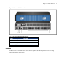
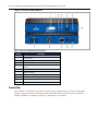
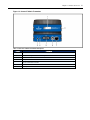
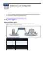
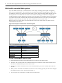
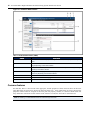
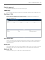
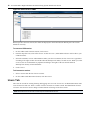
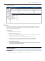
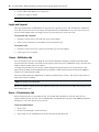
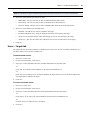
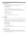
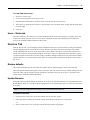
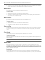
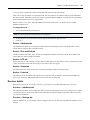
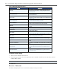
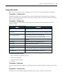
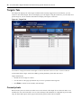
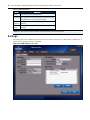
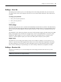
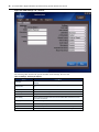
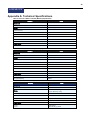
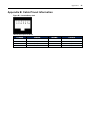
AVOCENT® MATRIX HIGH PERFORMANCE KVM SWITCHING SYSTEM
INSTALLER/USER GUIDE Avocent® Matrix High Performance KVM
Switching System
Installer/User Guide
Emerson, Emerson Network Power and the Emerson Network Power logo are trademarks or service marks of Emerson Electric Co. Avocent, the
Avocent logo, AMX and Dambrackas Video Compression are trademarks or service marks of Avocent Corporation or its affiliates in the U.S. and other
countries. All other marks are the property of their respective owners. This document may contain confidential and/or proprietary information of
Avocent Corporation, and its receipt or possession does not convey any right to reproduce, disclose its contents, or to manufacture or sell anything that it
may describe. Reproduction, disclosure, or use without specific authorization from Avocent Corporation is strictly prohibited. ©2013 Avocent
Corporation. All rights reserved.
NOTE: This document supports versions up to and including release 1.0.
590-1141-501A
i
TA B LE OF C ON TE N TS
Product Overview
Features and Benefits
1
1
Security
1
Flash upgrade
1
Video support
2
Audio support
2
USB support
2
On-Board Web Interface (OBWI)
2
On-Screen Display (OSD)
2
Matrix switch
2
Receiver
3
Transmitter
4
Installation and Configuration
Configuration Options
7
7
Single switch Matrix system
7
Multi-switch cascaded Matrix system
8
Switch Configuration
9
Setup Port
9
Unit information
9
Network configuration
9
Appliance mode
10
Username/password
10
Set session timeout
11
On-Board Web Interface
13
Common features
14
Forgotten password
15
OBWI Help
15
Dashboard Tab
15
User sessions pane
15
Events pane
15
Sessions Tab
15
Users Tab
16
New user
17
Login and Logout
18
Users – Attributes tab
18
Users – Permissions tab
18
ii Avocent® Matrix High Performance KVM Switching System Installer/User Guide
Users – Targets tab
19
Users – Favorites tab
20
Users – OSD tab
20
Users – OSD F1-F12 tab
20
Users – Status tab
21
Devices Tab
21
Restore defaults
21
Update firmware
21
Reboot device
22
Remove device
22
Remove offline
22
Flash display
22
Switch details
22
Receiver details
23
Transmitter details
25
Modes
26
Private mode
26
Share mode
26
Peripherals Tab
26
System Settings Tab
27
Save settings to file
27
Load settings from file
28
Restore full defaults
28
Restore partial defaults
28
OBWI tab
28
OSD
28
Events tab
29
Defaults
29
Other
29
Events Tab
30
on-screen display
Targets Tab
31
32
Connect private
32
Connect shared
33
Favorites
33
USB
33
Settings
34
Settings – User tab
35
Settings – Receiver tab
35
Table of Contents iii
Info Tab
37
Diagnostics Tab
37
Appendices
39
Appendix A: Technical Specifications
39
Appendix B: Cable Pinout Information
41
Appendix C: Technical Support
42
iv Avocent® Matrix High Performance KVM Switching System Installer/User Guide
1
1
Product Overview
The Avocent® Matrix High Performance KVM switching system is the next generation of Avocent keyboard, video and mouse (KVM) products. This new class of digital Matrix systems and extension products provides the high-performance, reliable desktop extension experience expected from an Avocent product. Combining the best of the previous generation, such as the instantaneous switching time of the Avocent AMX™ switching system and the digital quality and advanced management features of the Avocent HMX extender system, the digital Matrix switching solution offers a way to migrate to a digital solution while leveraging existing infrastructure.
In a typical scenario, numerous transmitter and receiver devices can connect in a Matrix fashion to communicate through the proprietary central switch or a network of switches. The switch handles the distribution of the data streams between transmitters and receivers. A single shielded twisted pair (STP) CAT 5e/6 cable, connects each transmitter and receiver to the switch. Users are linked to computers in real-time across a Matrix that connects video, USB peripherals and audio from a target computer to a receiver where the user can operate as if the computer is directly connected to a monitor, USB peripherals and speakers. The Matrix Switching System is the basis for an additional set of products intended to address the digital signage and Pro A/V, as IT and A/V equipment converge. This unified approach provides an enhanced digital Matrix switching solution for broadcast, post production and data centers (government, military and industrial).
Features and Benefits
• Transmitters are powered from the switch over STP CAT 5e/6
• Dual power supply switches (available on the 32-port switch)
• High speed USB is transparently presented to the target computer
• Transmitters, receivers, and switches are all equipped with full color LCD displays showing color coded unit status
• Transmitters support discrete cables for connection to the target video, USB and audio
Security
The switch system supports Secure Sockets Layer (SSL) over a TCP/IP connection and AES. Password protection is also provided to control access to all administration functions. Individual KVM users have usernames, passwords and a list of targets they are allowed to access. The type of allowed USB devices can be controlled on a per-user, per-receiver and per-transmitter basis.
Flash upgrade
The firmware may be upgraded at any time using various industry protocols to ensure that the system is always running the most current version available. Both the transmitter and the receiver are flash upgradable. 2 Avocent® Matrix High Performance KVM Switching System Installer/User Guide
Video support
The advanced Dambrackas Video Compression™ algorithm used by the system enables a pixel-accurate video experience with lag-free, real-time interaction with computing equipment. The resulting performance and speed provide new levels of content creation, production and delivery. Video is distributed in multiple formats supporting various connectors including DVI-D and VGA. Audio support
The Matrix receiver provides CD quality (Redbook) 44.1 kHz, 16-bit per channel stereo audio support.
USB support
The Matrix Switching System provides six USB version 2.0 connectors with an industry-leading combined throughput.
On-Board Web Interface (OBWI)
Administrators can manage the system through the OBWI (accessed with HTTPS). The OBWI runs on any supported browser that has network access to the switch. An administrator can use the OBWI to create user accounts and configure transmitters and receivers.
On-Screen Display (OSD)
The Matrix receiver includes an on-screen display that allows users to establish connections to the targets from the local keyboard and mouse.
Matrix switch The Matrix switch is a rack mountable chassis with RJ-45 ports to which the transmitters, receivers and switches connect. It is available in 20-port and 32-port models. The interconnection at the switch is a proprietary, nonroutable protocol. • Redundant power supplies (600W) on 32-port switch
• 350W single power supply on 20 port switch
• Transmitters are powered from the switch over STP CAT 5e/6
• Supports cascading (interconnecting switches) • Transmitter and receiver can connect to any port
• Dual Network Interface Card (NIC) for failover
• Setup port access for configuration
• Front or rear mounting possible Chapter 1: Product Overview 3 Figure 1.1: Avocent™ Matrix Switch
Table 1.1: Avocent™ Matrix Switch Descriptions
Number
Description
1
Power supplies (dual on 32-port switch)
2
RGB LCD and scroll buttons for device information
3
Dual NIC ports
4
Setup port
5
RJ-45 ports for KVM signaling
Receiver The Matrix receiver enables the desktop user’s monitor, speakers and USB peripherals to connect to a target computer through the Matrix switch. 4 Avocent® Matrix High Performance KVM Switching System Installer/User Guide
Figure 1.2: Avocent™ Matrix Receiver
Table 1.2: Avocent™ Matrix Receiver Descriptions
Number
Description
1
RGB LCD for color-coded status and device information
2
Audio connection
3
Microphone connection
4
USB 2.0 connections
5
External power button for turning on/off and resetting the
receiver
6
T-Channel locking for secure rack mounting
7
USB 2.0 connections
8
DVI-I video connection
9
RJ-45 ports for connection to the Matrix switch
10
Cable catch for securing the power cable
11
Power connector
Transmitter The transmitter is a small device with cables connecting video, USB and audio to a target. The transmitter captures, compresses and encodes the media streams and transmits them to the receiver over a proprietary network. It attaches to a computer, AV player, or other device to be extended.
Chapter 1: Product Overview 5 Figure 1.3: Avocent™ Matrix Transmitter
Table 1.3: Avocent™ Matrix Transmitter Descriptions
Number
Description
1
RGB LCD for color-coded status and device information
2
T-Channel locking for secure rack mounting
3
Audio connection
4
Microphone connection
5
DVI-D or VGA video connection
6
USB-B connector
7
RJ-45 port for connection to the Matrix switch
6 Avocent® Matrix High Performance KVM Switching System Installer/User Guide
7
2
Installation and Configuration
At this point you should have already mounted the switch and completed the installation instructions outlined in the Avocent® Matrix Switching System Quick Installation Guide. For important safety information on your Matrix switch, please visit http://www.emersonnetworkpower.com/ComplianceRegulatoryInfo. Configuration Options
Single switch Matrix system
In the figure below, multiple transmitters and receivers are attached to a single Matrix switch.
Figure 2.1: Example of Single Switch System
Table 2.1: Single Switch System Components
Number
Description
1
Target device
2
Matrix transmitter
3
Matrix switch
4
Matrix receiver
5
Audio connection (speakers)
6
Video connection
7
Microphone connection
8
Mouse connection
9
Keyboard connection
8 Avocent® Matrix High Performance KVM Switching System Installer/User Guide
Multi-switch cascaded Matrix system
Up to four Matrix switches may be interconnected to create a larger switching system capable of supporting more receivers and transmitters. This is referred to as a cascaded system. When cascading Matrix switches, you can seamlessly connect to any target device from a single list in the On-screen Display (OSD) interface, as if all the target devices were connected to one switch. To use seamless cascading, you will need to configure the cascaded switches as a master and slave(s). There can be only one master in a cascaded system. The switch that is set to master mode is used to administer the other switches, transmitters and receivers in the system through the OBWI. In a system with only one switch, that switch should always be set to master mode.
When a switch is set to slave mode, the web user interface on the switch will become very limited. A slave cannot administer other devices.
Figure 2.2: Example of a Multi-switch Cascaded System
Table 2.2: Cascaded Switch System Components
Number
Description
1
Matrix transmitter
2
Matrix switch
3
Matrix receiver
4
Ethernet
IP connection
Direct connection
To install a cascaded Matrix Switching System:
1. Position the Matrix switches to be attached and select a switch to be the master switch.
2. Attach one end of an STP cable into a numbered RJ-45 port on the master switch. Attach the other end of the cable to a numbered RJ-45 port on the slave switch.
3. You can now connect transmitters and receivers to numbered RJ-45 port on the cascaded master and slave switches.
4. When you have connected the transmitters and receivers to the switching system, you will need to configure the cascaded switch as a slave. Switch Mode on page 22.
5. You can repeat steps 2 through 4 to cascade a third or fourth switch.
Chapter 2: Installation and Configuration 9 Switch Configuration
After the Avocent Matrix Switching System has been installed, you can begin configuration. By default, DHCP is enabled on the switch. Once the switch receives an IP address, it is displayed on the LCD display on the back of the unit. You can begin configuration by using the setup port or using the On-board Web Interface (OBWI). For more information on the OBWI setup, see On-Board Web Interface on page 13.
Setup Port
The setup port on the back of the Matrix switch allows the administrator access to a menu for setup and configuration of the switch. From the serial menu you can configure network settings, setup or change passwords, upgrade the firmware or reset to factory defaults. NOTE: The default username and password is Admin with no password. When you login for the first time, you will be prompted to
change the password.
To access the serial menu:
1. Using a null modem cable, connect a terminal or a PC that is running terminal emulation software to the Setup port on the back panel of the Matrix switch. NOTE: The terminal settings are 9600 bits per second (bps), 8 bits, 1 stop bit, no parity and no flow control.
2. Connect the other end of the serial cable to the serial port of your computer.
3. Launch the terminal emulation software.
4. Press any key to login. 5. Enter the username and password.
To navigate through the serial menu, type the number or letter that corresponds to the option you wish to choose and press Enter. This action will bring you to a sub-menu or screen where you can make configuration changes. To exit a menu or screen and to confirm any configuration changes you have made, type 0 (zero) and press Enter.
Unit information
The unit information screen provides the following device information: EID, MAC address, Part Number, Serial Number, Boot Version and App Version. Network configuration
There are two network configuration options available for the Matrix switch, IPv4 or IPv6. The following table describes the options for configuring IPv4.
Table 2.3: IPv4 Configuration
Option
Dynamic Host
Configuration
Protocol (DHCP)
Description
The switch is a DHCP client and receives all the network
parameters from a DHCP server on the network.
10 Avocent® Matrix High Performance KVM Switching System Installer/User Guide
Option
Description
DHCP plus zeroconf
The switch attempts to obtain an IP address using
DHCP. If DHCP times out, then it uses zeroconf to
obtain an IP address. Zeroconf picks an IP address out
of the block 169.254.0.0/16. To use zeroconf the
network must use the 169.254.0.0/16 block of IP
addresses.
Zeroconf
The switch will immediately use zeroconf to determine
an IP address.
Static
The user will enter the IP address manually.
IP Address
The IP address of the switch.
Netmask
The Netmask of the switch.
Default Gateway
The default gateway of the switch.
The following table describes the options for configuring IPv6.
Table 2.4: IPv6 Configuration
Option
Description
Stateless only
The switch uses IPv6 stateless address
autoconfiguration to obtain an IPv6 address.
Dynamic Host
Configuration
Protocol (DHCP)
The switch is a DHCP client and receives all the network
parameters from a DHCP server on the network.
DHCP info only
The switch obtains configuration information from the
DHCP server but does not perform any address
assignment.
Static
The user will enter the IP address manually.
IP Address
The IP address of the switch.
Prefix Length
The size of the link-local prefix.
Default Gateway
The default gateway of the switch.
After the network has been configured, you can access the OBWI to add users and manage the Avocent™ Matrix Switching System.
Appliance mode
The appliance mode menu option allows you to toggle the switch between cascade master and cascade slave. If the switch is configured as a cascade slave, this option allows the administrator to select the cascade master using the switch EID. Username/password
The username/password menu allows the user to change the username and or password.
The change setup port password option allows the user to enable or change a setup port password. This will enable or disable access to the boot menu which allows the user to select the current or previous version of firmware for booting. While connected to the switch from the setup port, administrators can also select a boot image. W hen new firmware is loaded into Matrix switch, the switch keeps a copy of the previous version in a separate flash image. There is a short boot menu that allows the administrator to select which boot image is to be used. The boot menu is accessed in the first five5 seconds of booting by pressing any key. Chapter 2: Installation and Configuration 11 Set session timeout
The set session timeout option configures the setup port inactivity timeout. When the timeout for the setup port expires, the user is logged out.
12 Avocent® Matrix High Performance KVM Switching System Installer/User Guide
13
3
On-Board Web Interface
The On-Board Web Interface (OBWI) is a remote, web browser-based user interface that allows an administrator to manage users, switches, receivers and transmitters. The first time you log in to the administrator account, you will be required to set the account password.
NOTE: The OBWI and the Setup port use the same administrator account.
The following browsers are compatible with the OBWI:
• Microsoft Internet Explorer® 9 or 10
• Mozilla Firefox® 17 Extended Service Release
To log in to the Matrix switch OBWI:
1. Launch a web browser.
2. In the address field, enter the IP address of the Avocent™ Matrix switch. Use https://<IP Address> as the format.
3. Enter your username and password, then click Login.
NOTE: The default username and password is Admin with no password.
14 Avocent® Matrix High Performance KVM Switching System Installer/User Guide
Figure 3.1: On-Board Web Interface
Table 3.1: On-Board Web Interface (OBWI)
Number
Description
1
Tab bar - Use the tab bar to display and manage users, sessions, devices, peripherals, settings and
events.
2
Side bar- The sidebar is used to initiate actions related to the current tab. The content of the sidebar
changes depending on which tab is selected.
3
Details pane - The details pane shows information about the currently selected item(s) and changes
depending on what item is selected.
4
Display pane - The display pane is used to display lists of users, receivers and transmitters. The
contents vary depending on the tab that is selected.
5
Help
6
OBWI preferences for the currently logged in user.
7
Log out
Common features On most tabs, there is a list of items in the upper pane, and the properties of those items are shown in the lower pane. More than one item can be selected on most lists using Ctrl + click. If more than one item is selected, the properties of those items are “merged” in the lower pane. If a property conflicts, it is shown as blank. Some text entry fields have restrictions on their content. If the content is invalid, the field will be outlined in red.
NOTE: An asterisk (*) on a tab indicates that there are unsaved changes on that tab.
Chapter 3: On-Board Web Interface 15 Forgotten password
If you forget the administrator password, contact technical support.
OBWI Help
You can access the online help for the Matrix switch by clicking the Help button in the top right of the screen.
Dashboard Tab
When you login to the OBWI, the tab that is shown by default is the Dashboard tab. The Dashboard tab displays current session information, user information and events.
Figure 3.2: Dashboard Tab
User sessions pane
The user sessions pane lists the current KVM sessions and details the user that is logged in, the transmitter and receiver that are being used by the KVM session, whether the session is shared or private and how long the session has been active.
Events pane The events pane displays a list of recent events including the date and time of the event, the type of event and a brief description. The events can be either informational events or errors that may require further attention.
Sessions Tab
The Sessions tab allows you to view and connect or disconnect KVM sessions. 16 Avocent® Matrix High Performance KVM Switching System Installer/User Guide
Figure 3.3: Sessions tab in OBWI
When a specific session is selected, the details are displayed in the bottom Session Details pane. The session details are read only. To connect a KVM session:
1. On the sidebar under Connect Session, click Connect.
2. From the drop-down list, select either Private or Shared session (other authorized users will be able to join a shared session).
3. Select the username, receiver and transmitter. When you select a username, the list of receivers is populated according to the rights of that user and the allowed shared/private mode(s) of each receiver. When you select a receiver, the list of transmitters is populated according to the rights of the user and the allowed shared/private mode(s) of each transmitter.
4. Click Connect.
To disconnect a session:
1. Select a session from the list of active sessions. 2. On the sidebar under Disconnect Session, click Disconnect. Users Tab
The Users tab is used for creating, deleting and logging users in or out of receivers. An administrator must create a user account for each user. There is a limit of 80 user accounts on a master switch. The administrator account on a slave switch can be used to change a limited amount of settings on the slave switch. NOTE: Slave switches do not have user accounts except for the administrative account.
Chapter 3: On-Board Web Interface 17 Figure 3.4: Users Tab
New user
When a user has been created, you can configure the permissions, targets, OSD settings and set up a list of favorites for the user. By selecting more than one user, you can change the permissions, targets, settings and favorites for multiple users at the same time. To create a user:
1. On the sidebar under New User, click New.
2. In the Attributes tab, enter the following:
a. Username - The name that the user will log in with. It must consist of a combination of up to 20 letters and numbers, must be unique and is case-sensitive. b. Full name - The full name field is for informational purposes only and is not required.
c. Allow Blank Password - Select the drop-down list to enable or disable a blank password.
d. Change Password - Enable must be selected in order to set the initial user password
e. Enter and confirm the password.
f. Account Status - Select the drop-down list to choose to Disable or Enable the account. The user will only be able to login if the account is enabled.
3. Click Save. If the Save button is not enabled, there is an error in the Attributes, such as the two password fields not matching.
NOTE: The only required field for creating a user is the username on the Attributes tab. Each tab is independent and can be edited
after the user has been created.
To Delete a User:
1. From the Users pane, select a user or CTRL + click to select multiple users.
18 Avocent® Matrix High Performance KVM Switching System Installer/User Guide
2. On the sidebar under Delete User, click Delete.
3. Click Delete again to confirm.
NOTE: You cannot delete all administrator accounts.
Login and Logout The Login option allows an administrator to log a user into a specific receiver. The user must have permissions to be able to access the receiver. The Logout user option allows an administrator to log a user out of a receiver. You can select multiple users to be logged out, but you can only log in one user at a time.
To log a user into a receiver:
1. From the Users tab, select a user and click Login on the sidebar.
2. Select a receiver from the list of available receivers and click Login. To log out a user:
1. From the Users tab, select one or more users and click Logout on the sidebar.
2. Click Logout User to confirm.
Users – Attributes tab
The user attributes tab is used for editing the user account information including, username, password and the account status. The username is the name used for logins. It must consist of a combination of up to 20 letters and numbers, must be unique and is case-sensitive. To change the password on a user account, enable Change Password and enter the new password twice. The password may be blank if Allow Blank Password is enabled. A blank password must be set from the OBWI (it cannot be set to blank from the OSD).
The account status allows the administrator to enable or disable the user account . The user will only be able to login if the account is enabled.
NOTE: The full name is not a required field.
If there is a conflict in options between the different selected users, the option will be blank and that option will not be affected on a save.
Users – Permissions tab
On the permissions tab you can change the role, access mode and USB mode for each user. There are two options available for the user roles: User or Administrator. An administrator can login to the OBWI and perform all functions. A user can only log in to a receiver. To set user permissions:
1. Select a user.
2. On the User Details pane, click Permissions.
3. Select either User or Administrator for the user role from the drop-down list.
Chapter 3: On-Board Web Interface 19 NOTE: An administrator can log into the OBWI and perform all functions without restriction. A user can log in only to a Receiver.
4. Select one of the following for the access mode:
• Shared Only - The user will only be able to establish shared KVM sessions.
• Private Only - The user will only be able to establish private KVM sessions.
• Private or Shared - The user will be able to establish either shared or private KVM sessions.
5. Select one of the following for the USB mode:
• Disabled - No USB devices will be extended to the target. • Keyboard and Mouse only - Only the keyboard and mouse will extend to the target.
• All devices except mass storage - Only mass storage devices are not extended to the target.
• All devices - The user can connect any USB device into a receiver and extend it to the target.
6. Click Save.
Users – Targets tab
The Targets tab lists all of the transmitters available for the switch. From the list of available transmitters, you can add or remove access for the available users. To add transmitter access:
1. Select one or more users.
2. On the User Details pane, click Targets.
3. Select one or more transmitters from the Available Transmitters list and click Add.
-orClick Add All to add all of the transmitters to the Allowed Transmitters list.
-orCheck the box to enable access to all targets. Enabling all targets allows access to all current targets and any targets that are added in the future.
4. Click Save.
To remove transmitter access:
1. Select one or more users.
2. On the User Details pane, click Targets.
3. Select one or more transmitters from the Allowed Transmitters list and click Remove.
-orClick Remove All to remove all of the transmitters from the Allowed Transmitters list.
-orUn-check the box to enable access to all targets.
4. Click Save.
20 Avocent® Matrix High Performance KVM Switching System Installer/User Guide
Users – Favorites tab
The Favorites tab allows the administrator to create a quick list of transmitters that are accessed most often by the user. The list can be arranged in any order and can contain up to 32 transmitters.
To add a transmitter to favorites:
1. Select one or more users.
2. On the User Details pane, click Favorites.
3. Select one or more transmitters from the list of Available Transmitters and click Add.
4. Select the transmitter from the Favorites List and click Move Up or Move Down to move the transmitter on the lists as desired. The selected order will determine how the transmitters are displayed in the OSD.
5. Click Save.
To remove a transmitter from favorites:
1. Select one or more users.
2. On the User Details pane, click Favorites.
3. Select one or more transmitters from the Favorites List and click Remove.
4. Click Save.
Users – OSD tab
The OSD tab allows the administrator to customize the OSD hotkeys and configure the OSD inactivity timeout for each user.
The OSD hotkey is the shortcut key that the user presses on his keyboard to display the OSD. The per-user OSD Hotkey setting applies only when that user is logged into a receiver. There is a system wide default that applies when no user is logged into a receiver. This default is found under System Settings on the OSD tab.
The OSD inactivity timeout sets the time after which the OSD will be automatically dismissed if there is no user keyboard or mouse activity.
To change the OSD settings:
1. Select one or more users.
2. On the User Details pane, click OSD.
3. Select the OSD Hotkey from the drop-down list. 4. Enter the OSD Inactivity Timeout in minutes. If the inactivity timer is set to 0, the timeout will be disabled. 5. Click Save.
Users – OSD F1-F12 tab
The OSD F1-F12 is for creating action hotkeys for the receiver OSD. For example, you can set the F1 key to connect to a specific target when logged into the OSD. You can create shortcut key assignments so that when the OSD is displayed, you can press one of the F1 through F12 keys on your keyboard to initiate a common action, such as connecting to a specified target.
Chapter 3: On-Board Web Interface 21 To create OSD shortcut keys:
1. Select one or more users.
2. On the User Details pane, click OSD F1-F12.
3. Select the desired function key and then select an action from the drop-down list. 4. The Connect to Target X action requires a specific target to be specified. Select a target from the drop-down list to the right.
5. Click Save.
Users – Status tab
The Status tab shows the current receiver login and KVM sessions for the selected user(s). Typically, there will be only one session listed per user, but a user can have multiple sessions. The tab displays the username, the receiver, the transmitter and the duration of the session.
Devices Tab
From the Devices tab, you can manage switches, transmitters and receivers. This includes viewing and changing settings, updating firmware, and resetting to factory defaults. The current list of devices known to the master switch (including itself) is shown in the upper Devices pane. When a new device is physically connected to a switch in the system, it will automatically appear on the list. If a device is physically removed from the system, it will still appear on the list but will show a status of Offline. Settings for that device are retained in the master switch. If the device is connected again in the future, its settings will be pushed from the master switch down to the device.
Restore defaults
The restore full defaults option will restore the complete factory default settings to the device(s) selected. The restore partial defaults option applies only to switches. This will restore the factory default settings with the exception of the network settings. Network settings are excluded so that you do not have to reconnect to the switch using a potentially different IP address.
Update firmware
The update firmware option updates the firmware for the device(s) selected. Firmware can be updated using FTP, HTTP, HTTPS, TFTP, or a local file. Firmware update files are not retained when power is removed or the switch is rebooted.
NOTE: You can select multiple devices to be updated, but you must select devices of the same type.
To update the firmware:
1. From the Devices tab, select one or more similar devices and click Update. 2. If the desired file is already stored in the switch, select the file from the list of existing files. -or3. Select a source for the new file and provide the necessary details as prompted.
22 Avocent® Matrix High Performance KVM Switching System Installer/User Guide
4. Click Proceed to proceed with the firmware update. Progress can be seen by watching the status column on the list of Devices pane. The final completion status is logged to the Events tab.
Reboot device
One or more devices can be rebooted remotely from the Devices tab.
To reboot a device:
1. From the Devices tab, select one or more devices and click Reboot. 2. Click Reboot to confirm. The status of the device will change to reboot pending, offline and then back to ready when the device completes rebooting.
Remove device
Devices that are no longer being used can be removed from the Matrix switch.
To remove a device:
1. From the Devices tab, select one or more devices and click Remove.
2. Click Remove to confirm. The device will be removed from the list. Remove offline
All offline devices can be removed by using the clicking Remove Offline - Remove. This provides a convenient way for you to clean up your list of devices after one or more devices have been physically removed from the system.
Flash display
The LCD display can be set to flash to help locate a transmitter, receiver or switch. To flash the LCD display:
Select one or more devices, then click Flash in the sidebar. You will be prompted to enter the length of time to flash the backlight. NOTE: A value of zero can be used to stop a backlight that is currently flashing.
Switch details
When in the Devices tab, if you select a switch, you will be able to view and edit options for the switch including the mode, attributes and the IP address. The options you can edit depend on whether the switch is the master (the one you are logged into), a slave, or a switch that belongs to a different cascade system. All options are editable on the master. Some options are editable on a slave. No options are editable on a master or slave that belongs to a different cascade system.
Switch Mode
You can change the mode of the switch you are logged in to by changing the cascade participation setting. Changing from master to slave or slave to master has significant implications. If you change a switch from master Chapter 3: On-Board Web Interface 23 to slave or slave to master, the switch will automatically reboot to effect the change.
There can be only one master in a cascaded system. The switch that is set to master mode is used to administer the other switches, transmitters and receivers in the system through the OBWI. In a system with only one switch, that switch should always be set to master mode.
When a switch is set to slave mode, the OBWI on the switch will become very limited. A slave cannot administer other devices. To change the mode:
1. Select a switch from the list of devices.
NOTE: You can only change the mode of the switch you are logged in to.
2. On the Mode tab, select the desired cascade participation from the drop-down list.
3. Click Save.
Switch – Attributes tab The Attributes tab allows you to change the name, location and description of the switch. The name of each switch must be unique within a cascaded system.
Switch – IPv4 and IPv6 tab
The IPv4 and IPv6 tabs allow you to choose the configuration method used for the switch, the IP address, the subnet mask, the gateway address and DNS.
Switch – NTP tab
On the NTP tab you can configure a primary and secondary time server that will be used to synchronize the time of day clock on the switch. The time of day is used when events are logged.
Switch – Status tab
The Status tab for the switch shows basic, read-only information about the selected switch.
Switch – Ports tab
The Ports tab for the switch lists all of the devices connected to the switch ports. It lists the port number, the device type, the device EID and the status for each of the devices connected.
Receiver details
When in the Devices tab, if you select a receiver, you will see a list of tabs applicable only to receivers. Receiver – Attributes tab
The Attributes tab allows you to change the name, location and description of the receiver. Each receiver within a system must have a unique name. The Location, Description and Notes fields are optional, and are used only for your own information.
Receiver – Settings tab
From the Settings tab, you can change various settings for the receiver. The following table describes the receiver settings. 24 Avocent® Matrix High Performance KVM Switching System Installer/User Guide
Table 3.2: Receiver Settings Descriptions
Setting
Description
Auto Login
When enabled, a specified user is automatically logged into the
receiver whenever it is turned on and physically connected to a
switch in the system.
Auto Login Username
When Auto Login is enabled, this identifies the user that will be
logged in to the receiver.
Auto Connect
After a user logs into this receiver (either manually or because of an
auto login), the receiver will automatically connect a KVM session to
a specified target.
Auto Connect Target
When Auto Connect is enabled, this identifies the target to which
the receiver will be automatically connected.
Auto Connect Mode
When Auto Connect is enabled, this option determines the mode
(Shared or Private) that will be used for the connection.
USB Mode
Determines what USB devices will be extended from this receiver
to a target.
LCD Backlight
Determines whether the LCD backlight will be on or off.
Allowed Access
Determines the type of connections this receiver can establish
(Shared, Private or either).
Video Scaling
If enabled, the video will be scaled to match the resolution of the
attached monitor if the target is outputting a different resolution.
Audio Output
Controls whether any audio output from the target is used to drive
the green audio output jack on the receiver.
Microphone
Controls whether any signal from the pink microphone jack on the
receiver is sent over the KVM session to the connected target.
Keyboard Auto Enumeration
If enabled, the keyboard will be re-enumerated when connecting to
a target.
Mouse Auto Enumeration
If enabled, the mouse will be re-enumerated when connecting to a
target.
Session Timeout
If there is no keyboard or mouse activity for this amount of time, the
KVM session will be terminated and the user logged out of the
receiver.
Share control timeout
When the keyboard and mouse are idle for this amount of time,
another user on a shared KVM session can gain control of the
keyboard and mouse.
To edit the receiver settings:
1. Select a receiver from the list of devices.
2. On the Settings tab there are several options that can be enabled or disabled, use the drop-down menus to configure those options. NOTE: When some options are enabled, they may require additional information. For example, auto login will require a username.
3. Click Save.
Receiver – Status tab The Status tab displays the receiver serial number, EID, status and port number.
Chapter 3: On-Board Web Interface 25 Transmitter details
When in the Devices tab, if you select a transmitter, you will see a list of tabs only applicable to transmitters.
Transmitter – Attributes tab
The attributes tab allows you to change the name, location and description of the transmitter. Each transmitter within a system must have a unique name. The Location, Description and Notes fields are optional, and are used only for your own information.
Transmitter – Settings tab
From the settings tab, you can change various settings for the transmitter. The following table describes the transmitter settings. Table 3.3: Transmitter Setting Descriptions
Setting
Description
Icon
The icon that will appear on the target list on the OSD to represent this
target.
Wake on LAN
Enables the transmitter to send a Wake on LAN signal to the target when a
KVM session is established. This can be used to wake a sleeping computer.
Wake on LAN MAC address
The MAC address to which the Wake on LAN signal should be sent. Use
MAC-48 or MAC-64 format such as xx:xx:xx:xx:xx:xx or
xx:xx:xx:xx:xx:xx:xx:xx, where each x is a hexadecimal digit. You may also
use hyphens instead of colons, such as xx-xx-xx-xx-xx-xx.
USB mode
Determines what USB devices will be extended to the attached target by this
transmitter.
LCD backlight
Determines whether the LCD backlight will be on or off.
Allowed access
Determines the type of connections that can be established with this
transmitter (Shared, Private or either).
Traffic priority
Determines whether USB or video traffic should be given higher priority.
Audio output
Controls whether any audio output from the target, connected to the green
jack on the transmitter, will be sent across the KVM session to the receiver.
Microphone input
Controls whether any microphone audio sent across the KVM session will be
passed on to the target via the pink jack on the transmitter.
To edit the transmitter settings:
1. Select a transmitter from the list of devices.
2. Click on the Settings tab.
3. Change the desired settings.
4. Click Save.
Transmitter – Status tab
The Status of the transmitter including, the serial number, EID, status and port number are displayed on the status tab.
Transmitter – Sessions tab
The Sessions tab for the transmitter displays all KVM sessions currently connected to the transmitter.
26 Avocent® Matrix High Performance KVM Switching System Installer/User Guide
Modes There are three modes available for users connecting to transmitters and receivers. The modes are Private only, Shared only and Private or Shared. The transmitter setting is the authority if there is conflict in the user or receiver setting. For example, if the transmitter is set to private only and user and/or receiver is set to shared only, the user will not be able to connect to the target. The Private or Shared mode is the default mode for devices.
Private mode
In Private only mode, no other receiver in the switching system can switch to that target device. If Private mode is not available, the user will be notified via an on screen message. If the transmitter is configured for private mode only, the share mode option will be grayed out and only private mode will be available.
Share mode
In Share mode, multiple users can connect to the audio and video of a target computer over the network and arbitrate for control of that computer. Share mode is the default mode, however, if the user has been given access by the administrator they will be able to choose private mode via a radio button. The shared only mode is the default mode for users.
Peripherals Tab
In order to understand the Peripherals Tab, you need to first understand what an EDID (Extended Display Identification Data) is. EDIDs are built in to video monitors so the computer that a monitor is connected to can query the monitor for its characteristics and capabilities. The computer’s video hardware can then drive the monitor according to the resolution and timing that the monitor can accept. This will affect, for instance, the resolution of the operating system’s desktop display.
When a Matrix transmitter is connected to a target computer, the transmitter takes the place of a real monitor, and it must act like a real monitor and present an EDID to the computer when queried. A transmitter with factory default settings will present a generic EDID that represents a fictitious monitor that supports all of the resolutions that can be handled by the Matrix system.
You can override this default EDID, by capturing an EDID from an actual monitor connected to a receiver, and push that EDID down to the transmitter. Then the computer attached to that transmitter will act just like it would if that monitor were directly connected to the computer.
There are several reasons why you might want to push a monitor’s EDID down to a transmitter. If the monitor does not support the highest resolution reported by the factory default EDID, then you could push the monitor’s EDID to the transmitter in order to prevent the computer’s operating system from driving the video output at the unsupported resolution. This will avoid requiring the receiver to scale the video down to the resolution required by the monitor. This may result in a crisper video image for the user and will allow a KVM session to be established more quickly (since the receiver does not have to change its video resolution and the monitor does not have to resynchronize). In a system where all or most of the monitors are the same, you might wish to push that monitor’s EDID to all the transmitters in order to eliminate the need for any video scaling when users establish connections to various targets
The Peripherals tab displays the attributes that may be captured from a monitor connected to a receiver. W hen a monitor is connected to a receiver, the monitor's EDID information can be pulled into the switch and stored. The Chapter 3: On-Board Web Interface 27 EDID information can then be pushed out to any available transmitter. If the transmitter and receiver are running the same resolution, establishing a video connection will be faster because the receiver will not have to change resolution and the monitor will not have to resynchronize with the resolution change.
The name of the peripherals and the description can be changed by selecting the monitor and editing the Attributes tab. The manufacturer ID and product code are read only fields.
The Monitors list is pre-populated with two read-only entries: the Avocent Default VGA EDID and Avocent Default DVI EDID. These are the factory default monitor attributes (EDIDs) that are presented to an attached target by the VGA and DVI transmitters, respectively. These entries provide a way to get back to the default EDID if you push a different EDID to a transmitter.
To pull monitor attributes:
1. On the sidebar under Pull Monitor, click Pull.
2. Select a receiver from the list and click Pull. The monitor will be added to the list in the Peripherals pane.
To push the monitor attributes:
1. On the sidebar under Push Monitor, click Push.
2. Select one or more transmitters from the list and click Push. The monitor attributes will be pushed to the selected transmitter(s).
To delete a monitor:
1. Select one or more monitors from the Peripherals pane.
2. On the sidebar under Delete Monitor, click Delete.
3. Click Delete to confirm.
System Settings Tab
The System Settings tab is where the OBWI settings and default settings are configured. All of the settings for a system can be saved or reloaded from the system settings tab.
Save settings to file
The save settings to file option allows you to store the system settings as a backup. The settings can be reloaded later to restore the system back to a previous state.
To save the system settings:
1. On the sidebar under Save Settings to File, click Save.
2. Enter a password if you wish to encrypt the file. Because the settings file includes potentially sensitive user authentication information, it is highly recommended that you provide a secure password to be used to encrypt the file.
3. Click Next.
4. Click the link in the dialog box to download the file.
28 Avocent® Matrix High Performance KVM Switching System Installer/User Guide
Load settings from file
Saved system settings can be reloaded to restore the system to a previous state.
To load system settings:
1. On the sidebar under Load Settings from File, click Load.
2. Click Next on the warning.
3. Browse to the path where the file is stored.
4. Enter the encryption password, if necessary, and click Next.
5. Click Reboot to reboot the switch.
Restore full defaults
The restore full defaults option will restore the switch to the full factory defaults, including the network settings. All user accounts will be deleted and all settings on the transmitters and receivers will also be reset to default. The restore will require the system to be rebooted. Restore partial defaults
The restore partial defaults option will restore the switch to factory defaults excluding the network settings. All user accounts will be deleted and all settings on the transmitters and receivers would also be reset to default. The restore will require the system to be rebooted. OBWI tab
The OBWI tab is for configuring the OBWI inactivity timeout, the OBWI banner and the Help URL. If the OBWI user has not interacted with the OBWI for this period of time, then that user will be automatically logged out. Entering zero for the timeout disables the function. The OBWI banner is the text that is displayed prior to login. The Help URL can be changed to a new location. By default, the link is already configured. OSD
The OSD tab is where you can edit the OSD banner and OSD hotkey for all receivers. The OSD banner, if enabled, allows you to change the text that is displayed on every receiver prior to login. The OSD hotkey is the system default hotkey for activating the OSD display. From the OSD tab, you can change the default hotkey and create a custom key sequence. To edit OSD settings:
1. Select System Settings - OSD.
2. From the drop-down list, select the Receiver OSD hotkey. If custom is selected, enter the custom key sequence.
3. Select the drop-down to enable or disable the Receiver OSD banner. 4. Enter the Receiver OSD banner text.
5. Click Save to push the changes to all attached receivers. Chapter 3: On-Board Web Interface 29 Events tab
The Events tab is where event logging is configured. Events can be manually downloaded to a file or automatically sent to a syslog server for longer term storage.
Individual events can be enabled or disabled by manipulating the Disabled Events and Enabled Events lists. Simply click on one or more events and click the buttons to move them from one list to the other.
The table below lists the options and descriptions for the Events tab.
Table 3.4: Events Tab Settings
Option
Description
Syslog Server IP
Address
The IP address of a syslog server that event log messages should be sent to when they are
generated.
Log Error Events
Controls whether Errors are recorded to the event log.
Log Warning Events
Controls whether warnings are recorded to the event log.
Log Informational
Events
Controls whether informational messages are recorded to the event log.
NOTE: Logged events are stored in volatile memory on the switch. If power is lost or the switch is reset then the list of events is
cleared.
Defaults
The Defaults tab is where the OSD and receiver session timeouts are set as well as the transmitter USB mode and traffic priorities are configured. These defaults apply when a new receiver or transmitter is added to the system.
Table 3.5: Default Tab Options Descriptions
Setting
Description
OSD Inactivity Timeout
The timeout, in minutes, after
which the OSD display disappears.
Receiver Session Timeout
The timeout, in minutes, after
which the user is logged out and his
KVM session terminated if there is
no keyboard/mouse activity at the
receiver.
Transmitter USB Mode
The default set for the transmitter
USB when a new transmitter is
added. By default, this is set to all
devices.
Transmitter Traffic Priority
The default for traffic priority on the
transmitter. By default, USB is the
priority.
Other
From the Other tab, you can set the time for the LCD backlight flashing feature. The LCD backlight flashing feature can help you identify a device. You can also enable or disable the settings for automatically rebooting after a firmware update. 30 Avocent® Matrix High Performance KVM Switching System Installer/User Guide
Events Tab
The Events tab is where the events enabled in the system settings are displayed and managed. From this tab you can download and save the event log history and acknowledge events. To acknowledge events:
1. From the Unacknowledged Events pane, select an event or Ctrl + click to select multiple events.
2. From the sidebar under Acknowledge, click Acknowledge.
To acknowledge all events:
From the sidebar under Acknowledge All , click Acknowledge All.
To save history:
From the sidebar under Save History, click Save.
To clear history:
From the sidebar under Clear History, click Clear.
NOTE: The current unacknowledged events will not be cleared.
31
4
on-screen display
The Avocent® Matrix Switching System incorporates an on-screen display (OSD), allowing users to manage the receiver and any connected transmitter from the local keyboard and mouse. The OSD is displayed on a monitor connected to a receiver. It has a list of available targets to which the user can connect. The OSD supports user defined hotkeys and favorites for frequently used actions.
The OSD will be positioned in the center of the screen and will be one of two sizes depending on current receiver resolution. The sizes are 640x480 and 960x720. The resolution used will be the preferred resolution of the monitor as identified by the monitor EDID. If the monitor EDID is not available, then the OSD will be 640x480 @ 60 Hz (VGA). If there is no video connection to a target, the OSD will use the display resolution on the receiver. From a receiver, press Print Screen to access the OSD. The default hotkey can be configured at the system level and for each user. Print Screen is the default. NOTE: When making changes in the OSD, the * on the tab indicates a change has been made that has not been saved.
32 Avocent® Matrix High Performance KVM Switching System Installer/User Guide
Targets Tab
The Targets tab displays all of the targets available for the currently logged in user. From the list, you can connect to the various targets. The list will display up to 300 targets. Using the search box, you can search for a specific target or you can click the radio button to display All Targets or Favorites.
Figure 4.1: Targets Tab
To connect to a target, first click on the target to select it then click Connect Private or Connect Shared.
To disconnect from a target, activate the OSD by pressing the hotkey, then click Disconnect.
Targets tab shortcuts:
• Double-click on a target to connect
• Use the arrows or the page up and down keys to move up and down the target list
• Press Enter to connect to the currently selected target.
Connect private
When connect private is selected, no other receiver can connect to that target device. If Private mode is not available, the user will be notified via an on screen message. If the transmitter is configured for private mode only, the share mode option will be grayed out and only private mode will be available.
Chapter 4: on-screen display 33 Connect shared
When connect shared is selected, multiple users can connect to the audio and video of a target computer over the network and arbitrate for control of that computer. Favorites
The edit favorites option allows the user to create a quick list of transmitters that are accessed most often. The list can be ranked in any order. By clicking on the radio button for Favorites, the list of favorites are displayed. To display all targets, click the All Targets radio button.
USB
The USB tab displays a list all of the USB connections on the receiver. If a USB device is connected, but not displayed in the list, this tab can be used to help troubleshoot. Figure 4.2: USB Tab
The following table describes the options available on the USB tab.
34 Avocent® Matrix High Performance KVM Switching System Installer/User Guide
Table 4.1: USB Tab Options
Option
Update
Description
Refreshes the list of attached USB devices.
Enumerates the selected device through to the target, as if you
Enumerate disconnected and reconnected the device from the receiver. This is
only available when you are connected to the target.
Map
Keyboard
Maps the selected device to the emulated keyboard on the
transmitter.
Map
Mouse
Maps the selected device to the emulated mouse on the
transmitter.
NOTE: The check-mark in the column indicates which keyboard and/or mouse is currently mapped.
Settings
The Settings tab has two additional tabs, one for the user and one for the receiver. Each tab has a different set of options and/or settings that can be configured.
Figure 4.3: OSD Settings Tab - User
Chapter 4: on-screen display 35 Settings – User tab
The Settings/User tab allows you to view and change some of the settings associated with your account. The user rights section of the User tab displays the user's role, access mode and the USB mode. These fields cannot be edited.
To change your password:
1. Enter your old (current) password.
2. Enter your new password.
3. Click Save.
OSD settings
The OSD settings allow the user to customize their OSD hotkeys and the inactivity timeout. The OSD inactivity timeout sets the time after which the OSD will be automatically dismissed if there is no user keyboard or mouse activity. The receiver OSD supports a 24 hour inactivity timeout. A value of zero (0) will disable the inactivity timeout. The OSD hotkey is the shortcut key that the user presses on his keyboard to display the OSD. The per-user OSD Hotkey setting applies only when that user is logged into a receiver. The default Hotkey is set by the system administrator. When logged in, you can override the default using a standard setting or a custom keycode sequence. A custom sequence requires you to know the USB keycode value(s) for your keyboard.
OSD F1-F12
The OSD F1-F12 is for creating action hotkeys for the receiver OSD. For example, you can set the F1 key to connect to a specific target when logged into the OSD. You can create shortcut key assignments so that when the OSD is displayed, you can press one of the F1 through F12 keys on your keyboard to initiate a common action, such as connecting to a specified target. To create or change a function key assignment, click Edit.
Settings – Receiver tab
The Receiver tab allows you to view and change some of the settings associated with the receiver you are connected to. NOTE: Only an Administrator can change these settings.
36 Avocent® Matrix High Performance KVM Switching System Installer/User Guide
Figure 4.4: OSD Settings Tab - Receiver
The following table describes the options available on the Settings - Receiver tab.
Table 4.2: Settings - Receiver Tab Options
Option
Description
Auto Login
Controls whether this receiver is automatically logged into a user account. This field is
read only.
Auto Connect
Controls whether this receiver automatically connects to a transmitter. This field is read
only.
USB Mode
Type of USB devices that are allowed for use with this receiver.
LCD Backlight
Option to turn the LDC backlight on or off.
Allowed Access
The type of access this receiver is allowed.
Video Scaling
Option to determine whether video from the transmitter will be scaled to the monitor
connected to the receiver.
Audio Output
Option for enabling audio at this receiver
Microphone
Option for microphone input for this receiver.
Keyboard Auto Enumerate
If enabled, the keyboard will be re-enumerated when connected to a target.
Mouse Auto Enumerate
If enabled, the mouse will be re-enumerated when connected to a target.
Chapter 4: on-screen display 37 Info Tab
The Info tab displays some information about the receiver and switch you are connected to. This information can be useful for troubleshooting. The following table describes the information available on the Info tab.
Table 4.3: Info Tab Descriptions
Field
Description
Name
The name of the receiver you are logged in to.
Firmware Version
The firmware version of the receiver.
Hardware Version
The hardware version of the receiver.
Part Number
The part number of the receiver.
EID
The electronic ID of the receiver.
Serial Number
The serial number of the receiver.
Switch Name
The name of the switch the receiver is connected to.
Switch EID
The electronic ID of the switch.
Switch IP address
The IP address of the switch.
Switch Port
The port on the switch where the receiver is connected.
Diagnostics Tab
The Diagnostics tab is used for debugging, but also contains general information about the receiver and allows you to reset a receiver or a transmitter.
To reset the receiver, click Reset Receiver. The reset option is similar to a power cycle.
To reset a transmitter, you must have a KVM session connected from your receiver to the transmitter you wish to reset. When you click Reset Transmitter, it resets the connected transmitter and is equivalent to powering the transmitter off and back on. You might reset a transmitter if there was no keyboard/mouse function after connecting to it. NOTE: Resetting a transmitter may affect other users if they are connected to the same transmitter in a shared session.
38 Avocent® Matrix High Performance KVM Switching System Installer/User Guide
39
APPENDICES
Ap p e n d ic e s
Appendix A: Technical Specifications
Table A.1: Avocent™ Matrix Transmitter (MXT5110) Specifications
Category
Value
Mechanical
Dimensions (DxWxH)
6.2 x 4.75 x 1.21 in.
Weight
1.4 lbs. / 0.64kgs
Ports/Connectors
USB
1 x Type B
Microphone
Microphone: 1 x 3.5mm stereo
Speaker
1x 3.5mm stereo
Video
1 x DVI-D or 1 x VGA
Direct Connect
1 x 8-pin modular
Power Supply
N/A
Table A.2: Avocent™ Matrix Receiver (MXR5110) Specifications
Category
Value
Mechanical
Dimensions (DxWxH)
4.9 x 8 x 1.21
Weight
1.6 lbs. / 0.73kgs
Ports/Connectors
USB
6 x Type B ( 2 front, 4 rear)
Microphone
1 x 3.5mm stereo
Speaker
1 x 3.5mm stereo
Video
1 x DVI-I
Direct Connect
1 x 8-pin modular
Power Supply
AC Input Range
100-240V
AC Input Frequency
50/60 Hz
Table A.3: Avocent™ Matrix Switch (MXS5120 and MXS5132) Specifications
Category
Value
Mechanical
Dimensions (DxWxH):
21.1 x 17.1 x 3.4 in.
Weight
20-port = 19.0 lbs (8.6 kg)
32-port = 24.8 lbs (11.2 kg)
Ports/Connectors
Network
2 x 10/100/1000 Ethernet
Setup
1 x 8-pin modular (RS-232 serial)
Direct Connect
1 x 8-pin modular (20 or 32 depending on model)
Power Supply
20-port
32-port
single, internal
dual (redundant), internal
40 Avocent® Matrix High Performance KVM Switching System Installer/User Guide
Category
Value
AC Input Range
100-240V
AC Input Frequency
50/60 Hz
Appendices 41 Appendix B: Cable Pinout Information
Figure B.1: Console/Setup Jack
Table B.1: Descriptions for Pinout
Pin Number
Description
Pin Number
Description
1
No Connection (N/C)
5
Transmit Data (TXD)
2
No Connection (N/C)
6
Signal Ground (SG)
3
No Connection (N/C)
7
No Connection (N/C)
4
Receive Data (RXD)
8
No Connection (N/C)
42 Avocent® Matrix High Performance KVM Switching System Installer/User Guide
Appendix C: Technical Support
Our Technical Support staff is ready to assist you with any installation or operational issues you encounter with your Avocent product. If an issue should develop, follow the steps below for the fastest possible service.
To resolve an issue:
1. Check the pertinent section of this manual to see if the issue can be resolved by following the procedures outlined.
2. Visit www.avocent.com/support and use one of the following resources:
Search the knowledge base or use the online service request
-orSelect Technical Support Contacts to find the Avocent Technical Support location nearest you.
For Technical Support:
http://www.avocent.com/support
590-1141-501A