1
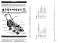
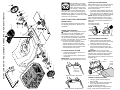
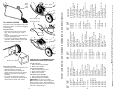
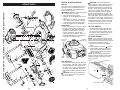
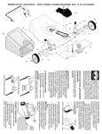
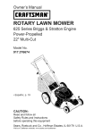
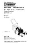
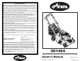
LIMITED WARRANTY
The Manufacturer warrants to the original consumer purchaser that this product as
manufactured is free from defects in materials and workmanship. For a period of
two (2) years from date of purchase by the original consumer purchaser, we will repair or replace, at our option, without charge for parts or labor incurred in replacing
parts, any part which we f nd to be defective due to materials or workmanship. This
Warranty is subject to the following limitations and exclusions.
1. This warranty does not apply to the engine, transaxle/transmission components,
battery (except as noted below) or components parts thereof. Please refer to the
applicable manufacturer's warranty on these items.
2. Transportation charges for the movement of any power equipment unit or attachment are the responsibility of the purchaser. Transportation charges for any
parts submitted for replacement under this warranty must be paid by the purchaser unless such return is requested by the manufacturer.
3. Battery Warranty: On products equipped with a Battery, we will replace, without
charge to you, any battery which we f nd to be defective in manufacture, during
the f rst ninety (90) days of ownership. After ninety (90) days, we will exchange
the Battery, charging you 1/12 of the price of a new Battery for each full month
from the date of the original sale. Battery must be maintained in accordance with
the instructions furnished.
4. The Warranty period for any products used for rental or commercial purposes is
limited to 45 days from the date of original purchase.
5. This Warranty applies only to products which have been properly assembled,
adjusted, operated, and maintained in accordance with the instructions furnished.
This Warranty does not apply to any product which has been subjected to alteration, misuse, abuse, improper assembly or installation, delivery damage, or to
normal wear of the product.
6. Exclusions: Excluded from this Warranty are belts, blades, blade adapters, normal wear, normal adjustments, standard hardware and normal maintenance.
7. In the event you have a claim under this Warranty, you must return the product to
an authorized service dealer.
Should you have any unanswered questions concerning this Warranty, contact:
HOP
Customer Service Department
1030 Stevens Creek Road
Augusta, GA 30907 USA
In Canada contact:
HOP
Customer Service Department
5855 Terry Fox Way
Mississauga, Ontario L5V 3E4
giving the model number, serial number and date of purchase of your product and
the name and address of the authorized dealer from whom it was purchased.
THIS WARRANTY DOES NOT APPLY TO INCIDENTAL OR CONSEQUENTIAL
DAMAGES AND ANY IMPLIED WARRANTIES ARE LIMITED TO THE SAME
TIME PERIODS STATED HEREIN FOR OUR EXPRESSED WARRANTIES.
Some areas do not allow the limitation of consequential damages or limitations
of how long an implied Warranty may last, so the above limitations or exclusions
may not apply to you. This Warranty gives you specif c legal rights, and you may
have other rights which vary from locale to locale.
This is a limited Warranty within the meaning of that term as def ned in the Magnuson-Moss Act of 1975.
Owner’s Manual
21547289 12.21.09 BY
• Español, p. 19
Printed in U.S.A.
Grass
catcher
Spark plug
Air f lter
Engine oil cap
with dipstick
Muff er
Drive cover
Mulcher door
Wheel adjuster
(on each wheel)
Housing
IMPORTANT: This lawn mower is shipped WITHOUT OIL OR GASOLINE in the engine.
MEETS CPSC SAFETY REQUIREMENTS
Sears rotary walk-behind power lawn mowers conform to the safety standards of the
American National Standards Institute and the U.S. Consumer Product Safety Commission. WARNING: The blade turns when the engine is running.
Operator presence control bar – must
be held down to the handle to start the
engine. Release to stop the engine.
Starter handle – used for starting engine.
6
Mulcher door – allows conversion to
discharging or bagging operation.
Drive control bar – used to engage
power-propelled forward motion of mower.
415226
73800400
137090
424200
430858
411952
36
38
40
41
54
57
DESCRIPTION
Drive Cover
Locknut, Hex
V-Belt
Kit, Wheel Adjuster, LH
(Includes Knob and Bearing)
Gear Case Assembly, Complete
Locknut, Hex 1/4-20
Spring
Kit, Wheel Adjuster, RH
(Includes Knob and Bearing)
Grassbag Assembly
Frame, Grassbag
401271X428
409148
146527
424201
28
29
33
35
Drive Control Assembly (Includes Cable)
Control Bar, Drive
Wheel & Tire Assembly, Front
E-Ring
Pinion
Dust Cover
Pawl, Drive
Washer, Flat 3/8
Bearing, Wheel Adjuster
Selector Knob
Retainer, Spring
Pan Head Tapping Screw #10-24 x 2-3/4
Fuel valve lever
194653
194185X428
193912X428
12000058
403849
189403
404845
67725
191039
701037
150495
175262
Gasoline f ller cap
1
7
11
12
13
14
15
16
17
18
19
27
Starter
handle
PART
NO.
Handle knob
KEY
NO.
Operator presence control bar
DESCRIPTION
Drive
control
bar
PART
NO.
These symbols may appear on your lawn mower or in literature supplied with the
product. Learn and understand their meaning.
KEY
NO.
READ THIS OWNER'S MANUAL AND ALL SAFETY RULES BEFORE OPERATING
YOUR LAWN MOWER. Compare the illustrations with your lawn mower to familiarize
yourself with the location of various controls and adjustments. Save this manual for
future reference.
ROTARY LAWN MOWER - - MODEL NUMBER A160H22 (MFG. I.D. NUMBER 96146000400)
KNOW YOUR LAWN MOWER
39
NOTE: All component dimensions given in U.S. inches. 1 inch = 25.4 mm.
IMPORTANT: Use only Original Equipment Manufacturer (O.E.M.) replacement parts. Failure to do so could be hazardous, damage your lawn mower and void your warranty.
OPERATION
15
17
36
14
13
ENGINE SPEED
The engine speed was set at the factory
for optimum performance. Speed is not
adjustable.
15
35
18
28
38
16
HOW TO USE YOUR LAWN MOWER
40
41
17
TO ATTACH GRASS CATCHER
1. Lift the rear door of the lawn mower
and place the grass catcher frame side
hooks onto the door pivot pins.
2. The grass catcher is secured to the
lawn mower housing when the rear
door is lowered onto the grass catcher
frame.
CAUTION: Do not run your lawn
mower without mulcher plate or plug, clipping def ector or approved grass catcher
in place. Never attempt to operate the
lawn mower with the rear door removed or
propped open.
Pivot pins
Rear
door
Grass
catcher
handle
16
11
12
13
Plate tab
LEVER FORWARD TO RAISE MOWER Lever
TO OPERATE DRIVE SYSTEM
• To start forward motion, lift drive control bar up to handle.
• To stop forward motion, release drive
control bar.
IMPORTANT: Always keep drive control
fully engaged against handle when in use.
14
18
TO ADJUST CUTTING HEIGHT
Raise wheels for low cut and lower wheels
for high cut, adjust cutting height to suit
your requirements. Medium position is
best for most lawns.
• To change cutting height, squeeze adjuster lever to ward wheel. Move wheel
up or down to suit your re
quirements. Be
sure all wheels are in the same setting.
NOTE: Adjuster is properly positioned
when plate tab inserts into hole in lever.
Also, 9-position adjusters (if so equipped)
allow lever to be positioned between the
plate tabs.
LEVER BACKWARD
TO LOWER MOWER
ENGINE ZONE CONTROL
CAUTION: Federal regulations require
an engine control to be installed on this
lawn mower in order to minimize the
risk of blade contact injury. Do not under
any circumstances attempt to defeat the
function of the operator control. The blade
turns when the engine is running.
• Your lawn mower is equipped with an
operator presence control bar which
requires the operator to be positioned
behind the lawn mower handle to start
and operate the lawn mower.
38
33
19
27
54
57
Operator
presence
control bar
1
DRIVE CONTROL ENGAGED
29
Catcher frame hook
7
ROTARY LAWN MOWER - - MODEL NUMBER A160H22 (MFG. I.D. NUMBER 96146000400)
11
12
29
The operation of any lawn
mower can result in foreign
objects thrown into the eyes,
which can result in severe
eye damage. Always wear
safety glasses or eye shields while oper ating your lawn mower or performing any
adjustments or repairs. W e recommend a
standard safety glasses or wide vision safety
mask worn over spectacles.
38
DRIVE CONTROL DISENGAGED
7
TO EMPTY GRASS CATCHER
1. Lift up on grass catcher using the
frame handle.
2. Remove grass catcher with clippings
from under lawn mower handle.
3. Empty clippings from bag.
NOTE: Do not drag the bag when emptying; it will cause unnecessary wear.
Discharge def ector
Your lawn mower was shipped ready to be
used as a mulcher. To convert to bagging
or discharging:
REAR BAGGING
• Open rear door and remove mulcher
plug. Store mulcher plug in a safe
place.
• You can now install the grass catcher or
optional clipping def ector.
• To convert to mulching or discharging
operation, install mulcher plug into rear
discharge opening of mower.
Mulcher plug
SIMPLE STEPS TO REMEMBER WHEN
CONVERTING YOUR LAWN MOWER
SIDE DISCHARGING
• Mulcher plug must be installed into rear
discharge opening of mower.
• Open mulcher door and install discharge def ector under door as shown.
• Mower is now ready for discharging
operation.
• To convert to mulching or bagging
operation, discharge def ector must be
removed and mulcher door closed.
FOR MULCHING 1. Rear mulcher plug installed.
2. Mulcher door closed.
FOR REAR BAGGING 1. Rear mulcher plug removed.
2. Grass catcher installed.
3. Mulcher door closed.
FOR SIDE DISCHARGING 1. Rear mulcher plug installed.
2. Discharge def ector installed.
CAUTION: Do not run your lawn
mower without mulcher plug or approved
grass catcher in place. Never attempt to
operate the lawn mower with the rear door
removed or propped open.
PART
NO.
427619X479
183567
850733X004
166649
66426
189713X428
750634
427414X428
401813X428
128415
150050
KEY
NO.
1
2
3
4
5
6
7
8
9
10
11
8
37
195622X479
410545X479
176655X479
140661X479
132004
194788
413160
405421
405423
409148
184193
Upper Handle
Engine Zone Control Cable
Bracket, Upstop
Mulcher Plug
Wire Tie
Handle Knob
Screw
Control Bar
Rear Door Assembly
Pop Rivet
Screw, Self-Tapping
#10-24 x 5/8
Screw, Hex Hex Head,
Sems 1/4-20 x 5/8
Back Plate
Side Baff e
Discharge Baff e
Rear Baff e
Keps Locknut 1/4-20
Rope Guide
Rear Skirt
Spring, Rear Door, LH
Spring, Rear Door, RH
Nut, Hex, Flanged
Bolt, Rear Door
DESCRIPTION
400247X428
174719
401630
401179X004
701037
401621X004
189917X428
401629
407493X005
27
28
29
30
31
32
33
34
35
402574X428
195917X479
195916X479
150406
45 175650
46 421176
47 406713
42 193000
43 73800400
44 417405
38
39
40
41
36 175735
37 428867
PART
NO.
KEY
NO.
Wheel & Tire Assembly, Rear
Bolt, Shoulder 3/8-16 x 1
Washer, Curved, Cylindrical
Axle Arm Assembly
Selector Knob
Selector Spring
Mulcher Door
Spacer
Wheel Adjusting Bracket,
Rear, RH
Hinge Bracket Assembly
Screw, Sems, Thread Cutting
5/16-18 x 3/4
Discharge Def ector
Handle Bracket, LH
Handle Bracket, RH
Screw, Hex Head, Threaded,
Rolled 3/8-16 x 1-1/8
Spring, Torsion
Nut, Hex, Nylock
Kit, Housing (Includes Key
Numbers 14, 15 and 51)
Rod, Hinge
Blade Adapter / Pulley
Blade, 22"
DESCRIPTION
PART
NO.
73930600
88652
51793
151590X479
191574
---
197991
422044X004
404764
430859
- - 430860
69
71
---
68 407492X005
55
56
57
58
59
64
52 404763
53 17600406
51 170031
48 851074
49 850263
50 851084
KEY
NO.
Washer, Hardened
Washer, Helical
Screw, Machine, Hex Head
3/8-24 x 1-3/8 Grade 8
Kit, Front Baff e
(Includes Key Number 53)
Danger Decal
Screw, Serrated,
Type TT 1/4-20
Locknut, Hex 3/8-16
Hinge Screw 1/4-20 x 1-1/4
Hairpin Cotter
Lower Handle
Handle Bolt
Engine, Honda, Model
Number GCV160-LAS3A
(See Breakdown)
Wheel Adjusting Bracket,
Rear, LH
Clip, Cable
Belt Keeper
Warning Decal (Not Shown)
Owner’s Manual,
English / Spanish
Owner's Manual, French
DESCRIPTION
NOTE: All component dimensions given in U.S. inches. 1 inch = 25.4 mm.
IMPORTANT: Use only Original Equipment Manufacturer (O.E.M.) replacement parts. Failure to do so could be hazardous, damage your lawn mower and void your warranty.
14
15
16
17
18
19
20
21
24
25
26
TO CONVERT MOWER
12 17060410
Open mulcher door
ROTARY LAWN MOWER - - MODEL NUMBER A160H22 (MFG. I.D. NUMBER 96146000400)
Grass
catcher
frame
handle
47
46
25
51
53
41
55
41
71
39
37
68
34
31
32
44
53
50
30 29
48
49
28
27
64
ADD OIL
Your lawnmower is shipped without oil in
the engine. For type and grade of oil to
use, see “ENGINE” in the Maintenance
section of this manual.
CAUTION: DO NOT overf ll engine with
oil, or it will smoke on startup.
1. Be sure lawnmower is level.
2. Remove oil f ll cap/dipstick from oil f ll
spout.
3. You recieve a container of oil with the
unit. Slowly pour the entire container
down the oil f ll spout into the engine.
4. Insert and tighten oil f ll cap/dipstick.
IMPORTANT:
• Check oil level before each use. Add oil
if needed. Fill to full line on dipstick.
• Change the oil after every 25 hours of
operation or each season. You may
need to change the oil more often
under dusty, dirty conditions. See “TO
CHANGE ENGINE OIL” in the Maintenance section of this manual.
TO STOP ENGINE
• To stop engine, release operator presence control bar. Wait until blade and
all moving parts have stopped and turn
fuel valve to OFF position if you do not
intend to restart the engine soon.
TO START ENGINE
NOTE: Due to protective coatings on the
engine, a small amount of smoke may be
present during the initial use of the product
and should be considered normal.
1. Be sure fuel valve is in the ON position.
) position.
2. Move choke lever to ON (
3. Hold operator presence control bar
down to the handle and pull starter
handle quickly. Do not allow starter
rope to snap back.
NOTE: The choke lever automatically
begins moving to the OFF position when
operator presence control bar is held
down to handle.
Gasoline
f ller cap
36
42
38
34
32
29
12
7
2
3
28
18
21
11
30
12
26
31
14
6
17
35
12
4
Upper
mark
37
40
33
56
20
5
59
45
69
55
57
58
56
52
41
43
Oil f ll cap /
dipstick
Lower
mark
Choke lever
OFF
ADD GASOLINE
• Fill fuel tank to bottom of tank f ller neck.
Do not overf ll. Use fresh, clean, regular
unleaded gasoline with a minimum of
87 octane. Do not mix oil with gasoline.
Purchase fuel in quantities that can be
used within 30 days to assure fuel freshness.
CAUTION: Wipe off any spilled oil or
fuel. Do not store, spill or use gasoline
near an open f ame.
ON (
)
ON
36
27
25
Fuel valve lever
15
26
10
24
9
1
19
6
16
8
ROTARY LAWN MOWER - - MODEL NUMBER A160H22 (MFG. I.D. NUMBER 96146000400)
CAUTION: Alcohol blended fuels
(called gasohol or using ethanol or methanol) can attract moisture which leads to
separation and formation of acids during
storage. Acidic gas can damage the fuel
system of an engine while in storage. To
avoid engine problems, the fuel system
should be emptied before storage of 30
days or longer. Empty the gas tank, start
the engine and let it run until the fuel lines
and carburetor are empty. Use fresh fuel
next season. See Storage Instructions for
additional information. Never use engine
or carburetor cleaner products in the fuel
tank or permanent damage may occur.
BEFORE STARTING ENGINE
REPAIR PARTS
9
OFF