1
`bob` Pa
pçÑíï~êÉ=réÖê~ÇÉ=sÉêëáçå=PKMu=
båÖäáëÜ
Contents
Contents
1
Installation ....................................................................................................................... 5
1.1
1.2
1.3
1.4
1.5
2
Software Upgrade Version 3.0X...................................................................................20
2.1
2.2
2.3
3
General information ..........................................................................................................................
General .............................................................................................................................................
2.2.1 CEREC 3D software ...............................................................................................................
2.2.2 Master Mode option ................................................................................................................
Entering the preparation margin .......................................................................................................
20
22
22
22
23
User interface of the CEREC 3D software ..................................................................24
3.1
3.2
3.3
2
General ............................................................................................................................................... 5
System requirements .......................................................................................................................... 5
Installing the CEREC 3D software ...................................................................................................... 6
Activating all milling instruments ......................................................................................................... 7
Installation of the software on the milling unit (download) .................................................................. 8
1.5.1 Installation using the DECT radio interface (Siemens Gigaset M101)...................................... 8
1.5.2 Procedure in case of problems with installation using the DECT radio interface (Siemens
Gigaset M101) ................................................................................................................................... 10
1.5.3 Installation using the Höft&Wessel radio interface ................................................................. 11
1.5.4 Procedure in case of problems with installation using the Höft&Wessel radio interface ........ 13
1.5.5 Installation using the Futaba FRH-SD03Tx radio interface .................................................... 14
1.5.6 Procedure in case of problems with installation using the Futaba FRH-SD03Tx radio interface
16
1.5.7 Installation using the serial cable supplied ............................................................................. 17
1.5.8 Procedure in case of problems with installation using the supplied serial cable .................... 19
Tool bar of the CEREC 3D software .................................................................................................
Menu bar of the CEREC 3D software ...............................................................................................
3.2.1 Restoration menu of the CEREC 3D software........................................................................
3.2.2 Settings menu of the CEREC 3D software .............................................................................
3.2.3 Window menu of the CEREC 3D software .............................................................................
3.2.4 "?" menu of the CEREC 3D software .....................................................................................
3D Preview: Deleting camera images ...............................................................................................
25
26
27
28
29
30
30
60 45 475 D 3344
D 3344.116.14.03.02 07.2007
Contents
4
User interface in Master Mode .....................................................................................31
4.1
4.2
4.3
4.4
4.5
4.6
4.7
4.8
4.9
4.10
4.11
4.12
4.13
4.14
4.15
4.16
60 45 475 D 3344
D 3344.116.14.03.02
Tool bar .............................................................................................................................................
Redefining the insertion axis .............................................................................................................
Overview of the restoration types and design techniques ................................................................
Restoration: Load .............................................................................................................................
Restoration: Delete ..........................................................................................................................
Restoration: Import ...........................................................................................................................
View window .....................................................................................................................................
Form tool ..........................................................................................................................................
Wax drop (Drop) ...............................................................................................................................
Settings: Instruments ........................................................................................................................
Configuration: Devices ......................................................................................................................
Configuration: Save ..........................................................................................................................
Configuration: Options ......................................................................................................................
Quadrant restoration (in Master Mode only) .....................................................................................
"Inlay Positioning" and "Unadjusted Crown" menu items no longer exist .........................................
New milling program .........................................................................................................................
07.2007
32
33
34
34
35
35
36
37
38
40
42
43
44
48
52
52
3
Contents
4
60 45 475 D 3344
D 3344.116.14.03.02 07.2007
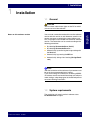
1 Installation
1
Installation
1.1
General
Notes on this software version
You can load a restoration made with an earlier software
version with this version as well. However, once this restoration has been saved with the current software version, it no longer can be loaded with the earlier software
version. The restoration can be saved according to the
following procedures:
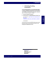
By selecting Restoration/Save (Ctrl+S)
By selecting Restoration/Save as....
Automatically, by confirming the image catalog with
the Next icon
Automatically, by pressing the Mill icon
Automatically, during virtual seating (Design/Quadrant)
i
NOTE
After the installation of the software, all parameters must
be set to the recommended factory setting.
If you are installing this software via an existing CEREC
3D software version and would like to keep your old parameter settings, adapt the program to the desired parameter values following installation:.
1.2
System requirements
The acquisition unit must have the hardware status
PC Hardware EA or higher.
60 45 475 D 3344
D 3344.116.14.03.02
07.2007
5
båÖäáëÜ
CAUTION
You must have administrator rights on the PC on which
you want to install the software!
1 Installation
1.3
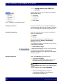
Performing the installation
Installing the CEREC 3D software
1. Insert the CEREC 3D DVD into the DVD drive.
The setup program starts automatically.
2. If this is not the case, run the Setup.exe file in the
root directory of the DVD.
3. Select the language of the installation and click the
OK button.
The installation wizard opens.
4. Click the Next button.
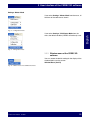
Continuing the installation
The license agreement then appears. If you accept the
license agreement, the program will continue with the
installation.
S Click the Yes button.
Selecting the standard installation
1. Click the Standard Installation button.
After the installation is complete, you may have the
ReadMe file displayed. This file contains up-to-date
information about the CEREC 3D software.
2. Select or deselect the checkbox and click the Finish
button.
i
NOTE
Once the new software has been installed, the new milling program must be transferred to the milling unit (see
"Installation of the software on the milling unit (download)" on page 8).
6
60 45 475 D 3344
D 3344.116.14.03.02 07.2007
1 Installation
1.4
Activating all milling
instruments
In the condition on delivery you can select the milling
instruments Step Bur 10 and Cylinder Pointed Bur in
the Change instruments/Left dialog. If you would like
all the milling instruments to be displayed for selection,
you can make this change as follows:
2. Download the file “inLab Instruments V 2.80” from
our website1 at : http://www.sirona.com/ecomaXL/index.php?site=SIRONA_COM_cerec_forthedentist_dowloads
and execute it.
The next time you start the CEREC 3D program you will
be able to select all of the milling instruments in the
Change instruments/Left dialog.
1. http://www.Sirona.com ->
PRODUCTS ->
CAD/CAM systems ->
for the Dentist ->
Downloads
60 45 475 D 3344
D 3344.116.14.03.02
07.2007
7
båÖäáëÜ
1. Close the CEREC 3D program.
1 Installation
1.5
Installation of the software on
the milling unit (download)
After installing the software update, it is necessary to
install the corresponding software on the milling unit
again.
1.5.1 Installation using the DECT radio
interface (Siemens Gigaset M101)
1. For this installation step place your acquisition unit /
PC as close as possible to the milling unit.
2. Switch the acquisition unit / PC on. The milling unit
must be switched off.
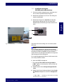
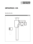
3. Switch the milling unit on (B) while you keep the
download key (A) pressed. Wait until the left operating indicator (C) of the radio interface on the milling
unit lights up continuously. You can now release the
Download key on the milling unit.
B
A
C
Fig. 1-1 Download key
The green LED on the milling unit is lit and the yellow
LED is off.
i
NOTE
For a software upgrade from Version 2.8X to Version
3.0X, the milling software is automatically downloaded to
the milling unit when the CEREC 3D user software is
started. In this case, the steps described are not required
after starting the inLab 3D program.
For a software upgrade from Version 2.6X or lower to Version 3.0X, proceed as follows.
8
60 45 475 D 3344
D 3344.116.14.03.02 07.2007
1 Installation
4. Start the CEREC 3D program.
9 The message The software is being loaded to
COMx1 appears in the status bar. Wait until the indicator goes out.
5. Select the menu item Settings/Configuration/Devices.
6. Select the milling unit to be configured in the Configure Devices dialog box and click the Configure button.
8. Place a checkmark in front of Scanner, in front of inLab gearhead installed and, if installed, in front of
Large watertank. Click OK.
9. After a successful download, a green check mark appears next to the milling unit symbol if the milling unit
and scanner were calibrated beforehand. Click the
OK button to close the Configure Devices dialog
box.
The installation is now completed. Should problems
have occurred in one of the above items, please observe
the instructions on the next page.
1. COM1, COM2, ... – depending on which interface the milling
unit/radio interface is connected to.
60 45 475 D 3344
D 3344.116.14.03.02
07.2007
9
båÖäáëÜ
7. Enter a name for this milling unit ("milling unit" is offered as the default name).
1 Installation
1.5.2 Procedure in case of problems with
installation using the DECT radio
interface (Siemens Gigaset M101)
S Make sure that the radio interface(s) is (are) correctly
connected.
S Run the acquisition unit / PC down and switch the acquisition unit / PC off. If a PC is used, pull the plug-in
power supply unit of the PC radio interface out from
the line socket for 5 seconds. Switch the milling unit
off. Restore the cable connections and test these.
Start again with Item 2. and make sure in this case
that all applications (e.g. CEREC/Sidexis/Videxis)
are closed.
S Open the menu Settings/Configuration/Communication. Select the desired milling unit in the Configure Devices dialog box and click the Configure button. Make sure that the correct COM interface and
baud rate are selected.
The baud rate must be set to 115200. If an acquisition unit is used, set the COM 1 port. When using a
PC set the port to which the radio interface is connected.
S Should the installation of the software on the milling
unit fail again, attempt the installation using the serial
cable supplied.
10
60 45 475 D 3344
D 3344.116.14.03.02 07.2007
1 Installation
1.5.3 Installation using the
Höft&Wessel radio interface
1. For this installation step place your acquisition unit /
PC as close as possible to the milling unit.
2. Switch the acquisition unit / PC on. The milling unit
must be switched off.
båÖäáëÜ
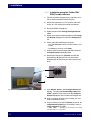
3. Switch the milling unit on (B) while you keep the
download key (A) pressed. You can release the
Download key on the milling unit after around 5 seconds.
B
A
The green LED on the milling unit is lit and the yellow
LED is off.
Fig. 1-2 Download key
i
NOTE
For a software upgrade from Version 2.8X to Version
3.0X, the milling software is automatically downloaded to
the milling unit when the CEREC 3D user software is
started. In this case, the steps described are not required
after starting the inLab 3D program.
For a software upgrade from Version 2.6X or lower to Version 3.0X, proceed as follows.
4. Start the CEREC 3D program.
9 The message The software is being loaded to
COMx1 appears in the status bar. Wait until the indicator goes out.
5. Select the menu item Settings/Configuration/Devices.
6. Select the milling unit to be configured in the Configure Devices dialog box and click the Configure button.
1. COM1, COM2, ... – depending on which interface the milling
unit/radio interface is connected to.
60 45 475 D 3344
D 3344.116.14.03.02
07.2007
11
1 Installation
7. Enter a name for this milling unit ("milling unit" is offered as the default name).
8. Place a checkmark in front of Scanner, in front of inLab gearhead installed and, if installed, in front of
Large watertank. Click OK.
9. After a successful download, a green check mark appears next to the milling unit symbol if the milling unit
and scanner were calibrated beforehand. Click the
OK button to close the Configure Devices dialog
box.
The installation is now completed. Should problems
have occurred in one of the above items, please observe
the instructions on the next page.
12
60 45 475 D 3344
D 3344.116.14.03.02 07.2007
1 Installation
1.5.4 Procedure in case of problems with
installation using the
Höft&Wessel radio interface
S Run the acquisition unit / PC down and switch the acquisition unit / PC off. Switch the milling unit off. Restore the cable connections and test these. Start
again with Item 2. and make sure in this case that all
applications (e.g. CEREC/Sidexis/Videxis) are
closed.
S Open the menu Settings/Configuration/Communication. Select the desired milling unit in the Configure Devices dialog box and click the Configure button. Make sure that the correct COM interface and
baud rate are selected.
The baud rate must be set to:
115200 (Höft&Wessel radio interface),
If an optical impression unit is used, set the COM 1
port. When using a PC set the port to which the radio
interface is connected.
S Should the installation of the software on the milling
unit fail again, attempt the installation using the serial
cable supplied.
60 45 475 D 3344
D 3344.116.14.03.02
07.2007
13
båÖäáëÜ
S Make sure that the radio interface(s) is (are) correctly
connected.
1 Installation
1.5.5 Installation using the Futaba FRHSD03Tx radio interface
1. For this installation step place your acquisition unit /
PC as close as possible to the milling unit.
2. Switch the acquisition unit / PC and the radio interface(s) on. The milling unit must be switched off.
3. Start the CEREC 3D program.
4. Select the menu item Settings/Configuration/Devices.
5. Select the milling unit to be configured in the Configure Devices dialog box and click the Configure button.
6. Check and edit the following if necessary:
- The COM interface to which the radio module is connected,
- The baud rate must be set to 19200.
7. Confirm these checks/changes with OK. Leave the
Configure Devices dialog box open.
8. Switch the milling unit on (B) while you keep the
download key (A) pressed. You can release the
Download key on the milling unit after around 5 seconds.
B
A
Fig. 1-3 Download key
9. Click Refresh status in the Configure Devices dialog box . The message Downloading software to
COMx1 appears in the status bar of the Configure
Devices dialog box. Wait until the indicator goes out.
10. Enter a name for this milling unit ("milling unit" is offered as the default name).
11. Place a checkmark in front of Scanner, in front of inLab gearhead installed and, if installed, in front of
Large watertank. Click OK.
1. COM1, COM2, ... – depending on which interface the milling
unit/radio interface is connected to.
14
60 45 475 D 3344
D 3344.116.14.03.02 07.2007
1 Installation
12. After a successful download, a green check mark appears next to the milling unit symbol if the milling unit
and scanner were calibrated beforehand. Click the
OK button to close the Configure Devices dialog
box.
båÖäáëÜ
The installation is now completed. Should problems
have occurred in one of the above items, please observe
the instructions on the next page.
60 45 475 D 3344
D 3344.116.14.03.02
07.2007
15
1 Installation
1.5.6 Procedure in case of problems with
installation using the Futaba FRHSD03Tx radio interface
S Make sure that the radio interface(s) is (are) correctly
connected.
S Run the acquisition unit / PC down and switch the acquisition unit / PC off. Switch the milling unit off. Restore the cable connections and test these. Start
again with Item 2. and make sure in this case that all
applications (e.g. CEREC/Sidexis/Videxis) are
closed.
S Open the menu Settings/Configuration/Communication. Select the desired milling unit in the Configure Devices dialog box and click the Configure button. Make sure that the correct COM interface and
baud rate are selected.
The baud rate must be set to:
19200 (Futaba FRH-SD03Tx radio interface).
If an optical impression unit is used, set the COM 1
port. When using a PC set the port to which the radio
interface is connected.
S Should the installation of the software on the milling
unit fail again, attempt the installation using the serial
cable supplied.
16
60 45 475 D 3344
D 3344.116.14.03.02 07.2007
1 Installation
1.5.7 Installation using the serial cable
supplied
1. Switch the acquisition unit / PC and the milling unit
on.
båÖäáëÜ
2. Switch the milling unit on (B) while you keep the
download key (A) pressed. You can release the
Download key on the milling unit after around 5 seconds.
B
A
The green LED on the milling unit is lit and the yellow
LED is off.
Fig. 1-4 Download key
i
NOTE
For a software upgrade from Version 2.8X to Version
3.0X, the milling software is automatically downloaded to
the milling unit when the CEREC 3D user software is
started. In this case, the steps described are not required
after starting the inLab 3D program.
For a software upgrade from Version 2.6X or lower to Version 3.0X, proceed as follows.
3. Start the CEREC 3D program.
9 The message The software is being loaded to
COMx1 appears in the status bar. Wait until the indicator goes out.
4. Select the menu item Settings/Configuration/Devices.
5. Select the milling unit to be configured in the Configure Devices dialog box and click the Configure button.
6. Enter a name for this milling unit ("milling unit" is offered as the default name).
1. COM1, COM2, ... – depending on which interface the milling
unit/radio interface is connected to.
60 45 475 D 3344
D 3344.116.14.03.02
07.2007
17
1 Installation
7. Place a checkmark in front of Scanner, in front of inLab gearhead installed and, if installed, in front of
Large watertank. Click OK.
8. After a successful download, a green check mark appears next to the milling unit symbol if the milling unit
and scanner were calibrated beforehand. Click the
OK button to close the Configure Devices dialog
box.
The installation is now completed. Should problems
have occurred in one of the above items, please observe
the instructions on the next page.
18
60 45 475 D 3344
D 3344.116.14.03.02 07.2007
1 Installation
1.5.8 Procedure in case of problems with
installation using the supplied serial
cable
S Open the menu Settings/Configuration/Communication. Select the desired milling unit in the Configure Devices dialog box and click the Configure button. Make sure that the correct COM interface and
baud rate are selected.
The baud rate must be set to 115200. When using an
acquisition unit with external interface extension set
the COM 2 port. When using an acquisition unit without external interface extension, you must proceed
as for a PC and select the port to which the serial cable is connected.
60 45 475 D 3344
D 3344.116.14.03.02
07.2007
19
båÖäáëÜ
S Run the acquisition unit / PC down and switch the acquisition unit / PC off. Switch the milling unit off. Restore all cable connections and test these. Make sure
that you have used the 2 meter long serial interface
cable supplied. Start again with Item 1. and make
sure in this case that all applications (e.g. CEREC/Sidexis/Videxis) are closed.
2 Software Upgrade Version 3.0X
2
Software Upgrade Version 3.0X
2.1
General information
i
NOTE
This software does not allow the loading, importing and
editing of bridge frameworks and implants.
Continuous further product development
In the course of continuous further product development
the CEREC 3D software has been developed further
regarding the points listed below:
"General" on page 22
The suggestions for inlays have been radically
revised / improved. The systems suggests
biogeneric tooth forms for the morphology of inlays.
The preparation margin is marked in a segment (see
"Entering the preparation margin" on page 23). The
segment borders no longer need to be marked with a
double click.
"User interface of the CEREC 3D software" on
page 24
"Tool bar of the CEREC 3D software" on page 25
"Menu bar of the CEREC 3D software" on page 26
"3D Preview: Deleting camera images" on page 30
"User interface in Master Mode" on page 31
"Tool bar" on page 32
When setting the insertion axis, undercuts in the area
of the preparation are marked in color. The insertion
axis is set after entering the preparation margin (see
"Redefining the insertion axis" on page 33).
The Position and Rotate tools can also be used with
inlays.
20
60 45 475 D 3344
D 3344.116.14.03.02 07.2007
The user interface has been revised:
- The New dialog box has been extended by a 3D view
(see "Overview of the restoration types and design
techniques" on page 34).
- The dialogs of the following menu items in the
Restoration menu have been extended by a 3D
preview:
Load (see "Restoration: Load" on page 34)
Delete (see "Restoration: Delete" on page 35)
Import (see "Restoration: Import" on page 35)
- The following dialogs allow you to assign an image to
each patient:
Create new patient
Edit patient data
The Cut tool is integrated in the View window (see
"View window" on page 36).
The Form and Drop tools have been provided with
new control elements (see "Form tool" on page 37
and "Wax drop (Drop)" on page 38).
The Options menu item has been reconfigured (also
see "Configuration: Options" on page 44).
- For acquisitions with the 3D camera, a crosshair
can be displayed as a positioning aid.
- Entering the contact points is no longer necessary
(determination of the proximal contact)
"Settings: Instruments" on page 40
"Configuration: Devices" on page 42
"Configuration: Save" on page 43
"Quadrant restoration (in Master Mode only)" on
page 48
""Inlay Positioning" and "Unadjusted Crown" menu
items no longer exist" on page 52
"New milling program" on page 52
60 45 475 D 3344
D 3344.116.14.03.02
07.2007
21
båÖäáëÜ
2 Software Upgrade Version 3.0X
2 Software Upgrade Version 3.0X
2.2
General
In order to effectively address the needs of new and
experienced CEREC users, the software has been split
into two parts - the CEREC 3D software and the Master
Mode.
2.2.1 CEREC 3D software
The CEREC 3D software has been optimized for easy
and efficient design of inlays, onlays and crowns with the
aid of the Dental database design technique with or
without antagonist.
It is not recommended to advance to Master Mode until
all the basic techniques of the CEREC method have
already been mastered.
A description of these functions can be found in the
chapter "User interface of the CEREC 3D software" on
page 24.
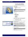
2.2.2 Master Mode option
You can set Master Mode by selecting Settings / Master
Mode from the menu. This displays all functions of the
software.
Fig. 2-1 Setting Master Mode
22
60 45 475 D 3344
D 3344.116.14.03.02 07.2007
2 Software Upgrade Version 3.0X
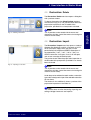
2.3
Entering the preparation margin
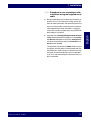
1. Start the entry by double-clicking anywhere on the
preparation margin.
2. Move the cursor along the preparation margin.
i
3. Continue this procedure until you are back at the
starting point.
4. Conclude the entry by double-clicking the starting
point.
Fig. 2-2 Entering the preparation margin
60 45 475 D 3344
D 3344.116.14.03.02
07.2007
23
båÖäáëÜ
NOTE
To support the automatic edge detection, click anywhere
near the margin on the raised side. There is an automatic
correction when the next point is set.
3 User interface of the CEREC 3D software
3
User interface of the CEREC 3D
software
In this chapter
This chapter contains:
"Tool bar of the CEREC 3D software" on page 25
"Menu bar of the CEREC 3D software" on page 26
"3D Preview: Deleting camera images" on page 30
24
60 45 475 D 3344
D 3344.116.14.03.02 07.2007
3 User interface of the CEREC 3D software
3.1
Tool bar of the CEREC 3D
software
Description of the icons
Create a new restoration
båÖäáëÜ
Acquire prepared tooth (preparation)
Acquire antagonist/registration
One design step forward
(Next)
One design step backward
(Undo)
Start the milling process
You can seize the tool bar with the mouse and position
it anywhere on the screen. It can be docked at the left,
right, top or bottom edge of the screen, as is usual with
Windows programs. It can be restored to its condition on
delivery by selecting Window/Reset (Ctrl+R).
60 45 475 D 3344
D 3344.116.14.03.02
07.2007
25
3 User interface of the CEREC 3D software
3.2
Fig. 3-1 Menu bar
Menu bar of the CEREC 3D
software
The menu bar at the top of the window allows you to
select further program functions which cannot be
accessed via the tool bars.
The following menus are available:
Restoration menu of the CEREC 3D software
Settings menu of the CEREC 3D software
Window menu of the CEREC 3D software
"?" menu of the CEREC 3D software
i
NOTE
Some menu functions can also be activated using the
shortcut keys specified in the menu item or the
corresponding icons on the tool bar.
26
60 45 475 D 3344
D 3344.116.14.03.02 07.2007
3 User interface of the CEREC 3D software
3.2.1 Restoration menu of the CEREC 3D
software
båÖäáëÜ
With the Restoration menu you can ...
Fig. 3-2 Restoration menu of the CEREC 3D software
open a window for a new restoration
Restoration/New... or Ctrl+N
load an existing restoration
Restoration/Load... or Ctrl+O
save a restoration
Restoration/Save... or Ctrl+S
save a restoration under another name or assign it to
another patient
Restoration/Save as...
export a restoration
Restoration/ Export...
send restoration data by e-mail
Restoration/Send to…
open a previous restoration or
quit the application with
Restoration/Exit
60 45 475 D 3344
D 3344.116.14.03.02
07.2007
27
3 User interface of the CEREC 3D software
3.2.2 Settings menu of the CEREC 3D
software
On the Settings menu, you can adapt and change the
following menu items:
Instruments
Configuration
Calibration
Master Mode
Fig. 3-3 Settings menu of the CEREC 3D software
Settings: Instruments
This menu item allows you to change worn/defective
milling instruments. Also refer to the chapter "Changing
burrs" in the Operation Instructions of the milling unit.
Settings: Configuration
Under this menu item, you can check and modify the
factory-set configurations.
Devices
Options
All connected milling units can be displayed and
configured under the Settings / Configuration /
Devices... menu item.
In the Options configuration dialog box you can activate
or deactivate the following:
Show frozen 3D image
If Show frozen 3D image is ticked, the measured data
are displayed 3-dimensionally after the optical
impression is released. The 2-dimensional still image is
no longer required.
Settings: Calibration
Under the Calibration menu item you can...
calibrate the 3D camera
(see chapter "Calibration of the 3D camera" in the
Operating Instructions for the acquisition unit).
CAUTION
The 3D calibration set is required for calibrating the 3D
camera.
The 3D calibration set must not be powdered.
calibrate the milling unit (see chapter on
"Calibrating the milling unit" in the Operating
Instructions for the milling unit).
28
60 45 475 D 3344
D 3344.116.14.03.02 07.2007
3 User interface of the CEREC 3D software
Settings: Master Mode
If you select Settings / Master Mode from the menu, all
functions of the software are shown.
If you select Settings / Exit Master Mode from the
menu, the default condition (CEREC 3D software) is set.
Fig. 3-5 Exiting Master Mode
3.2.3 Window menu of the CEREC 3D
software
You can restore the default setting for the display of the
windows/tool bar on the screen.
Window/Reset (Ctrl+R)
Fig. 3-6 Window menu of the CEREC 3D software
60 45 475 D 3344
D 3344.116.14.03.02
07.2007
29
båÖäáëÜ
Fig. 3-4 Setting Master Mode
3 User interface of the CEREC 3D software
3.2.4 "?" menu of the CEREC 3D software
If the Text prompts menu item is activated, the next
work step is described in a balloon in the status bar.
Fig. 3-7 Help menu of the CEREC 3D software
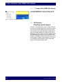
3.3
3D Preview:
Deleting camera images
Previously, when generating camera images in the 3D
preview, it was only possible to use a right click or double
click with the mouse to delete the last image created.
This functionality has been extended in version V3.00.
Now it is possible to delete any image via right click or
double click (newest image first) for each specific image
field (depending on where the cursor is located at the
moment). The deleted images go into the recycle bin of
the 2D image catalogue in the background. That means,
in an emergency these images would be accessible
again by switching into Master mode.
30
60 45 475 D 3344
D 3344.116.14.03.02 07.2007
4 User interface in Master Mode
4
User interface in Master Mode
In this chapter
This chapter contains:
"Tool bar" on page 32
"Redefining the insertion axis" on page 33
"Overview of the restoration types and design
techniques" on page 34
"Restoration: Load" on page 34
"Restoration: Delete" on page 35
båÖäáëÜ
"Restoration: Import" on page 35
"View window" on page 36
"Form tool" on page 37
"Wax drop (Drop)" on page 38
"Settings: Instruments" on page 40
"Configuration: Devices" on page 42
"Configuration: Save" on page 43
"Configuration: Options" on page 44
"Quadrant restoration (in Master Mode only)" on
page 48
""Inlay Positioning" and "Unadjusted Crown" menu
items no longer exist" on page 52
"New milling program" on page 52
60 45 475 D 3344
D 3344.116.14.03.02
07.2007
31
4 User interface in Master Mode
4.1
Tool bar
You can show or hide the Tool bar via the Window/Tool
bar menu bar.
Unavailable functions (e.g. Occlusion) appear dimmed.
Description of the icons
Create a new restoration
Load restoration
Save restoration
Scan/acquire prepared tooth
(preparation)
Scan/acquire unprepared tooth
(occlusion)
Scan/acquire dynamic occlusion impression
(articulation)
Scan/acquire antagonist/
registration
One design step forward
(Next)
One design step backward
(Undo)
Start the milling process
32
60 45 475 D 3344
D 3344.116.14.03.02 07.2007
4 User interface in Master Mode
4.2
Redefining the insertion axis
1. Select Design/Insertion axis.
The Insertion axis window opens.
2. Change the position of the preparation such that all
yellow markings disappear. If this is not possible,
(e.g. in the case of diverging stumps) make sure that
all preparation margins are completely visible from
the viewing direction and yellow-marked undercuts
are as far away as possible from the preparation
margin.
Fig. 4-1 Insertion axis
3. Then rotate the preparation model so that the model
is correctly identified by the axis designations
(mesial<->distal and lingual<->buccal). To do this,
rotate the preparation in the occlusal view by
grasping the right or left edge of the screen with the
mouse pointer and then moving the pointer along the
edge of the screen.
In the case of bridge frameworks, at least
"lingual<->buccal" must be labeled correctly.
4. Click the Fix button (Fig. 4-1).
The reference coordinate system for all further design
steps is changed.
60 45 475 D 3344
D 3344.116.14.03.02
07.2007
33
båÖäáëÜ
Regions within a preparation margin that show an
undercut from the viewing direction, are marked
yellow.
4 User interface in Master Mode
4.3
Overview of the restoration
types and design techniques
In the New dialog box, you can select the following and
confirm with OK:
Restoration
- Inlay, Onlay, Partial Crown
- Crown
i
NOTE
If the preparation margin of the crown (partial) is so high
that it cuts the proximal contact line of the crown
suggestion, the system will automatically switch from
crown to inlay.
Fig. 4-2
New dialog
- Veneer
Design technique
- Dental database
- Correlation
- Replication
- Articulation
Selectable teeth are shown in white and non-selectable
(inactive) teeth are shown in yellow in the odontogram.
4.4
Restoration: Load
The Restoration / Load menu item opens a dialog box
with preview window.
To display the preview, the Show Preview checkbox
must be ticked (Fig. 4-3). The preview shows either the
preparation impression or the 3D model of the
preparation, provided it has already been calculated.
i
Fig. 4-3 Loading a restoration with preview
NOTE
The 3D preview can be rotated with the mouse and
viewed from all sides (control the same as for rotating the
model in the 3D viewer).
i
NOTE
This software does not allow the loading, importing and
editing of bridge frameworks and implants.
34
60 45 475 D 3344
D 3344.116.14.03.02 07.2007
4 User interface in Master Mode
4.5
Restoration: Delete
The Restoration / Delete menu item opens a dialog box
with a preview window.
To display the preview, the Show Preview checkbox
must be ticked (Fig. 4-4). The preview shows either the
preparation impression or the 3D model of the
preparation, provided it has already been calculated.
Fig. 4-4 Deleting a restoration
4.6
Restoration: Import
The Restoration / Import menu item opens a standard
Windows file dialog box in which a file search of all PC
drives (hard disks, floppy disks and CDs) can be
performed to find compressed CEREC restorations. If
the selected file ("*.cdt", "*.sdt", "*.idt" or "*.dat") is a
CEREC restoration, it will open. If not, it will not open,
and an error message will be displayed.
The preview shows either the preparation impression or
the 3D model of the preparation, provided it has already
been calculated.
Fig. 4-5 Importing a restoration
i
NOTE
The 3D preview can be rotated with the mouse and
viewed from all sides (control the same as for rotating the
model in the 3D viewer).
Under the preview window the tooth number, restoration
type and the design technique of the selected restoration
file are shown.
The thumbnail view additionally shows a preview of the
preparation impression in the folder list.
i
NOTE
This software does not allow the loading, importing and
editing of bridge frameworks and implants.
60 45 475 D 3344
D 3344.116.14.03.02
07.2007
35
båÖäáëÜ
i
NOTE
The 3D preview can be rotated with the mouse and
viewed from all sides (control the same as for rotating the
model in the 3D viewer).
4 User interface in Master Mode
4.7
Introduction
View window
You can show or hide this window via the Window/View
menu item.
Inactive functions appear dimmed.
You can drag the window with the mouse by seizing its
title bar and drop it at any position on the screen. When
you select Window/Reset, the window returns to its
default position (right screen margin).
In this section
The following functions are described in this section:
A: Standard views
B: Zoom tool
C: Hiding/showing the neighboring teeth (Trim)
A
D: Showing/hiding the contact to the neighboring
tooth (Contact)
E: Cut tool
B
C
F: Showing/hiding the occlusion/articulation
G: Showing/hiding the antagonist
D
E
F
G
36
60 45 475 D 3344
D 3344.116.14.03.02 07.2007
4 User interface in Master Mode
4.8
Form tool
By clicking the Form button you can activate/deactivate
the Form tool.
Fig. 4-6 Form button
You can use this function to:
Applying material,
Removing material,
Removing
material
Blending
material
Blending material.
Clicking on the symbol activates the corresponding
mode.
Fig. 4-7 Form tool
båÖäáëÜ
Applying
material
Alternatively:
You can also use the space bar on the keyboard to
change functions in the following order:
Apply -> Remove -> Blend -> Apply ...
Changing the size of the layer to be applied
When you start this tool, the diameter of the layer to be
applied is 1.65mm.
The slider allows you to modify the size of the layer to be
applied.
Alternatively:
You can also modify the layer size (orange-colored area)
by right-clicking the restoration:
Fig. 4-8 Slider
Increase layer size – push mouse forward while
holding down the right mouse button.
Decrease layer size – drag mouse backward while
holding down the right mouse button.
The next layers will be applied using this size. This size
remains active until you change the size again or
deactivate the Form tool.
The ratio between material thickness and radius of the
applied layer is 1:70.
60 45 475 D 3344
D 3344.116.14.03.02
07.2007
37
4 User interface in Master Mode
4.9
Wax drop (Drop)
You can activate/deactivate the wax drop function by
clicking the Drop button.
Fig. 4-9 Drop button
You can use this function to:
Applying material,
Removing material,
Applying
material
Removing
material
Fig. 4-10 Drop tool
Blending
material
Blending material.
Clicking on the symbol activates the corresponding
mode.
Alternatively:
You can also use the space bar on the keyboard to
change functions in the following order:
Apply -> Remove -> Blend -> Apply ...
Modifying the wax drop size
The slider allows you to modify the size of the wax drops.
Alternatively:
If you click on the restoration with the right mouse button,
you can modify the size of the wax drops:
Enlarge wax drop – push the mouse forward with the
right mouse button pressed.
Reduce wax drop – pull the mouse backward with the
right mouse button pressed.
The next drops can be applied in this size. The size is
retained until it is modified again or until the wax drop
function is deactivated.
Fig. 4-11 Enlarging wax drops
Applying material
Application can be performed in two ways:
Drop by drop, by clicking the desired point of the
restoration
Apply a row of drops in material color by holding
down the left mouse button and moving the cursor.
The density of the drops is controlled by the speed
with which you move the cursor.
38
60 45 475 D 3344
D 3344.116.14.03.02 07.2007
4 User interface in Master Mode
Removing material
Removal can be performed in two ways:
Drop by drop, by clicking the desired point of the
restoration
Remove a row of orange-colored drops by holding
down the left mouse button and moving the cursor.
The density of the drops is controlled by the speed
with which you move the cursor.
The cursor assumes the shape of a hand and can then
be used to blend or smoothen the surface locally; to do
so, press and hold down the left mouse button.
60 45 475 D 3344
D 3344.116.14.03.02
07.2007
39
båÖäáëÜ
Blending material
4 User interface in Master Mode
4.10 Settings: Instruments
See also the chapter “Changing burs" in the Operating
Instructions for the milling unit.
1. Select the menu item Settings/Instruments.
i
NOTE
If several milling units are connected, a dialog box will
appear from which you must select the desired milling
unit and confirm with OK.
Fig. 4-12 Menu item: Instruments
If the (optional) bur set 2 is integrated in CEREC MC XL,
a dialog is opened which allows you to select the bur set
in which you want to change a milling instrument.
The motors run to the position for changing the milling
instruments (burs).
The Change instruments dialog box opens.
2. Select the milling instrument you would like to
change to and click Start.
Fig. 4-13 Selecting a bur set
40
60 45 475 D 3344
D 3344.116.14.03.02 07.2007
4 User interface in Master Mode
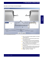
Description of the Change instruments dialog box
B
båÖäáëÜ
A
C
A’
B’
D
E
Fig. 4-14 Changing milling instruments (burs)
A, B – The milling instruments selected in lists A', B'
are displayed here.
A', B' – Here you can select the milling instruments
you would like to insert.
The milling instrument last inserted is preselected.
C – The milling instruments last used are displayed
here. This display remains unchanged even if you
click other milling instruments under A', B' .
D – The calls to action you must implement next are
displayed here.
E – You can select whether only the left, only the right
or both milling instruments are to be replaced here.
Start – Changes the milling instrument.
Cancel – Operation is canceled
60 45 475 D 3344
D 3344.116.14.03.02
07.2007
41
4 User interface in Master Mode
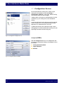
4.11 Configuration: Devices
All connected devices (milling units, inEos) can be
displayed and configured under the Settings /
Configuration / Devices... menu item. Several milling
units and one inEos can be managed.
A green check mark next to a device denotes its active
availability, e.g. this milling unit can be selected for
milling.
A red cross indicates that this device cannot be selected,
e.g. this milling unit is currently performing a milling
operation or its calibration data are invalid.
A yellow exclamation mark indicates that the current
milling program must be loaded into the milling unit (see
Operating Instructions for the milling unit).
Fig. 4-15 Configuration: Configure Devices
Configure (CEREC)
With the Configure button you can subsequently edit
the name and connection settings and configure various
parameters.
inLab gearhead installed
Large watertank
Scanner
Fig. 4-16 Configuring devices (CEREC)
42
60 45 475 D 3344
D 3344.116.14.03.02 07.2007
4 User interface in Master Mode
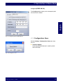
Configure (CEREC MC XL)
båÖäáëÜ
The Configure button allows you to subsequently edit
the name and IP address.
Fig. 4-17 Configuring devices (CEREC MC XL)
4.12 Configuration: Save
With the Settings / Configuration / Save menu item,
you can:
Connect database
An existing SIRONA database is used for patient
data and images.
Fig. 4-18 Configuration: Save
60 45 475 D 3344
D 3344.116.14.03.02
07.2007
43
4 User interface in Master Mode
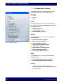
4.13 Configuration: Options
The Options configuration dialog box offers several
groups of functions which can be selected and
deselected:
Crown
General
inEos
Crown
In the Crown group, you can select or deselect new
parameters which are then automatically executed at
the appropriate point.
Settling on page 44
Cusp settling on page 45
Virtual grinding on page 45
General
In the General group, you can select or deselect the
following options:
Show all warnings on page 45
Trim step active on page 46
Fig. 4-19 Configuration: Options
Virtual keyboard on page 46
High resolution model on page 46
3D Preview on page 46
Show frozen 3D image on page 46
Camera crosshair on page 47
Start in Master Mode on page 47
inEos
In the inEos group, you can select or deselect the
following options:
Show model material dialog on page 47
Use marked calibration parts on page 47
Settling
(applicable only for posterior tooth crowns,
crown restoration type, dental database or replication
design technique)
44
60 45 475 D 3344
D 3344.116.14.03.02 07.2007
4 User interface in Master Mode
If this check mark is set (Fig. 4-19), the restoration is
automatically adapted to the antagonist during the
generation of the initial suggestion for a posterior tooth
crown with antagonist. The restoration is adapted to the
antagonist so that the resulting contact situation is as
stable as possible. The contacts should have as little
penetration volume as possible. The morphology of the
occlusal surface is not changed.
(applicable only for posterior tooth crowns,
crown restoration type,
dental database or replication design technique)
If this check mark is set (Fig. 4-19), individual cusps of
the restoration are automatically adapted to the
antagonist during the generation of the initial suggestion
for a posterior tooth crown with antagonist. The cusps
are adapted to the antagonist so that the resulting
contact situation is as stable as possible. The
morphology of the occlusal surface is changed.
i
NOTE
If both Settling and Cusp settling are activated in the
options, first Settling and then Cusp settling will be
executed in the initial suggestion process.
Virtual grinding
(applicable only for posterior tooth crowns,
crown restoration type, dental database or replication
design technique)
If this check mark is set (Fig. 4-19), virtual grinding of the
existing occlusal contacts will be performed at the end
of the calculation of an initial suggestion for a posterior
tooth crown with antagonist. The red contacts which you
set in the Parameter dialog box under Occlusal
contacts strength are thus removed down to one
strength.
Show all warnings
If you have hidden individual warnings1, you can have
them displayed again by setting a check mark in front of
Show all warnings.
1. have set a check mark in front of Do
not display this
warning again
60 45 475 D 3344
D 3344.116.14.03.02
07.2007
45
båÖäáëÜ
Cusp settling
4 User interface in Master Mode
Trim step active
If a check mark is set in front of Trim step active, you
can remove image regions before entering the
preparation margin.
If a check mark is NOT set in front of Trim step active,
this step will be skipped and you can continue with
trimming the antagonist (if present) or with entering the
preparation margin.
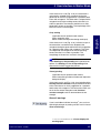
Virtual keyboard
If Virtual keyboard is ticked, a virtual keyboard will be
displayed (Fig. 4-20). You can use this screen keyboard
to simulate any commands previously executable only
via keyboard (e.g.: connecting through with the space
bar for Form or Drop) with the mouse as well.
i
Fig. 4-20 Configuration: Options/Virtual keyboard
NOTE
This option was primarily implemented so that the
CEREC 3D program could be operated completely via
mouse when using the CEREC Chairline.
You can close the Virtual keyboard window in the usual
Windows manner or by deactivating the check box in
front of the Virtual keyboard.
High resolution model
If the performance of your graphic card is sufficient, you
can select a more detailed model view by ticking High
resolution model.
3D Preview
If a check mark is placed in front of 3D Preview and the
performance of your graphic card is sufficient, the 3D
Preview will be used instead of the image catalog.
Show frozen 3D image
If Show frozen 3D image and 3D Preview are ticked,
the measured data are displayed 3-dimensionally after
the optical impression is released. The 2-dimensional
still image is no longer required.
46
60 45 475 D 3344
D 3344.116.14.03.02 07.2007
4 User interface in Master Mode
Camera crosshair
If Camera crosshair is ticked, a crosshair is displayed
in the center of the live image of the 3D camera as a
positioning aid. Direct the camera crosshair onto the
center of the tooth you want to acquire.
Start in Master Mode
Show model material dialog
If inEos is selected as the acquisition system, a dialog
box for selecting the material to be scanned appears
after the New dialog box.
If you always use the same material, you can save this
setting by removing the check mark in the Show model
material dialog box after you have selected the material
to be scanned.
In this case the dialog box will be suppressed.
If you want to redisplay the dialog box, you must set the
check mark in the Show model material dialog box
again.
Use marked calibration parts
Tick this option if you use a blue-marked calibration part
B and a blue-marked calibration cylinder. After this,
perform a complete inEos calibration (see inEos
Operating Instructions).
60 45 475 D 3344
D 3344.116.14.03.02
07.2007
47
båÖäáëÜ
If this is ticked, CEREC 3D will start in Master Mode the
next time.
4 User interface in Master Mode
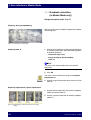
4.14 Quadrant restoration
(in Master Mode only)
Design example for teeth 14 to 17
Preparing, drying and powdering
After you have made and dried the preparation, powder
the working field.
Fig. 4-21 Powdering the working field
Acquiring tooth 16
1. After you have selected a patient from the database
or created a new patient, select the following options
in the New dialog box:
- Restoration type: Inlay
- Design technique: Dental database
- Tooth 16
i
NOTE
If an inlay is also to be provided, then start with this
restoration.
2. Click OK.
The arrow cursor automatically jumps to the Acquire
preparation icon.
3. Acquire an optical impression of the central cavity for
tooth 16.
Acquiring supplementary optical impressions
1. Acquire optical impressions of the mesial neighbors
(tooth 15 and then tooth 14).
2. Acquire an optical impression of the distal neighbor
(tooth 17).
Fig. 4-22 Supplementary optical impressions in the image
catalog
48
60 45 475 D 3344
D 3344.116.14.03.02 07.2007
4 User interface in Master Mode
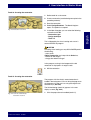
Tooth 16: Creating the restoration
1. Define tooth 16 as the center.
2. Create a restoration (see the design examples in the
preceding sections).
3. Save the restoration.
4. Select Design/Quadrant . The New dialog box
opens. The patient is accepted.
Fig. 4-23 Restoration of tooth 16
5. In the New dialog box, you can select the following
and confirm with OK:
båÖäáëÜ
- Restoration type
- Design technique
- Tooth 15
This is followed by the virtual seating and start of a
second CEREC 3D program.
CAUTION
Following virtual seating you may NO LONGER perform
the following:
- return to the
Optical impression work step with the Undo icon,
- remove or add images,
- change the reference image!
In the program running in the foreground, the old
restoration is displayed in its original state.
6. Mill the restoration.
Tooth 15: Creating the restoration
The program with the virtually seated restoration is
loaded in the background. You can bring the program to
the foreground via the task bar or by pressing the task
selection keys (Alt+Tab).
The finished design (tooth 16) appears in the new
display as tooth (Fig. 4-24).
1. Click the preparation to be edited (tooth 15).
Fig. 4-24 Tooth 16 seated virtually,
restoration of tooth 15
60 45 475 D 3344
D 3344.116.14.03.02
07.2007
49
4 User interface in Master Mode
2. Click the Fix button (Fig. 4-25).
3. Trim the model.
4. Click the Next icon.
5. Draw the preparation margin.
6. Select the Design/Insertion axis menu item.
7. Define the Insertion axis for tooth 15 (see
"Redefining the insertion axis" on page 33).
Fig. 4-25 Center...
8. Click the Fix button (Fig. 4-26).
9. Click the Next icon.
10. Create a restoration (see the design examples in the
preceding sections).
11. Save the restoration.
12. Select Design/Quadrant .
Fig. 4-26 Insertion axis
This is followed by the virtual seating and start of a
second CEREC 3D program.
13. Mill the restoration.
Tooth 14: Creating the restoration
1. Create the restoration for tooth 14 analogously to
tooth 16 and 15.
2. Save the restoration.
Fig. 4-27 Tooth 16 and 15 seated virtually,
restoration of tooth 14
3. Mill the restoration.
50
60 45 475 D 3344
D 3344.116.14.03.02 07.2007
4 User interface in Master Mode
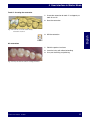
Tooth 17: Creating the restoration
1. Create the restoration for tooth 17 analogously to
tooth 16 and 15.
2. Save the restoration.
Fig. 4-28 Tooth 16, 15 and 14 seated virtually,
restoration of tooth 17
båÖäáëÜ
3. Mill the restoration.
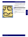
All restorations
1. Polish the proximal surfaces.
2. Insert the inlays with adhesive bonding.
3. Carry out the milling and polishing.
Fig. 4-29 Inlays inserted with adhesive bonding and milled
60 45 475 D 3344
D 3344.116.14.03.02
07.2007
51
4 User interface in Master Mode
4.15 "Inlay Positioning" and
"Unadjusted Crown" menu
items no longer exist
The Inlay Positioning and Unadjusted Crown menu
items no longer exist. These functions are now executed
automatically.
4.16 New milling program
The Software Upgrade Version 3.0X includes a new milling program. After the installation procedure, the milling program must be downloaded to the milling unit
(see "Installation of the software on the milling unit
(download)" on page 8).
52
60 45 475 D 3344
D 3344.116.14.03.02 07.2007
båÖäáëÜ
4 User interface in Master Mode
60 45 475 D 3344
D 3344.116.14.03.02
07.2007
53
tÉ=êÉëÉêîÉ=íÜÉ=êáÖÜí=íç=ã~âÉ=~åó=~äíÉê~íáçåë=ïÜáÅÜ=ã~ó=ÄÉ=êÉèìáêÉÇ=ÇìÉ=íç=íÉÅÜåáÅ~ä=áãéêçîÉãÉåíëK
«=páêçå~=aÉåí~ä=póëíÉãë=dãÄe=OMMP
a=PPQQKNNSKNQKMPKMO===MTKOMMT
péê~ÅÜÉW=ÉåÖäáëÅÜ=
ûKJkêKW= NMU=TTR
páêçå~=aÉåí~ä=póëíÉãë=dãÄe
áå=íÜÉ=rp^W
áå=`~å~Ç~W
c~Äêáâëíê~≈É=PN
SQSOR=_ÉåëÜÉáã
dÉêã~åó
ïïïKëáêçå~KÅçã
páêçå~=aÉåí~ä=póëíÉãë=ii`
QUPR=páêçå~=aêáîÉI=pìáíÉ=NMM
`Ü~êäçííÉI=k`=OUOTP
rp^
páêçå~=`~å~Ç~
PORM=oáÇÖÉï~ó=aêáîÉ=J=råáí=R
jáëëáëë~ìÖ~I=låí~êáç=iRi=RvS
`~å~Ç~
mêáåíÉÇ=áå=dÉêã~åó
fãéêáã¨=Éå=^ääÉã~ÖåÉ
lêÇÉê=kç
SM=QR=QTR=a=PPQQ