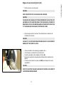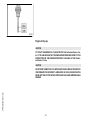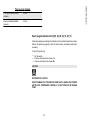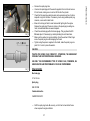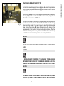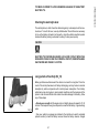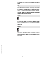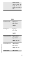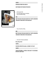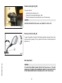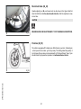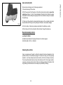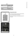
1
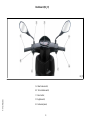
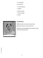
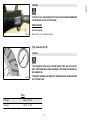
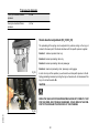
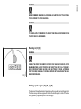
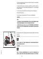
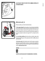
APRILIA WOULD LIKE TO THANK YOU
for choosing one of its products. Please read this manual carefully before riding your vehicle for the first time. It contains information, suggestions and
precautions on the use of your vehicle and it will allow you to get familiar with all its different characteristics. It will also help to get the maximum result
and pleasure from your purchase and it will confirm you one more time that you have made the right choice. This booklet is an integral part of the vehicle
and must be given to the new owner if the motorcycle is sold.
SR Motard 125
Ed. 01_03/2012
The instructions given in this manual are intended to provide a clear, simple guide to using your vehicle; it also describes routine maintenance procedures
and regular checks that should be carried out on the vehicle at an Aprilia Dealer or Authorised Workshop. The booklet also contains instructions for
simple repairs. Any operations not specifically described in this booklet require the use of special tools and/or particular technical knowledge: for these
operations, please take your vehicle to an Aprilia Dealer or Authorised Workshop.
2
Personal safety
Failure to completely observe these instructions will result in serious risk of personal
injury.
Safeguarding the environment
Sections marked with this symbol indicate the correct use of the vehicle to prevent damaging the environment.
Vehicle intactness
The incomplete or non-observance of these regulations leads to the risk of serious
damage to the vehicle and sometimes even the invalidity of the guarantee
The signs that you see on this page are very important. They are used to highlight parts
of the booklet that should be read with particular care. The different symbols are used
to make each topic in the manual simple and quick to locate.
3
4
INDEX
VEHICLE......................................................................................
Dashboard................................................................................
Instruments...............................................................................
Key switch.................................................................................
Locking the steering wheel....................................................
Releasing the steering wheel................................................
Switch direction indicators........................................................
Horn button...............................................................................
Light switch...............................................................................
Start-up button..........................................................................
Opening the saddle...............................................................
Keys..........................................................................................
Identification..............................................................................
Rear top box opening................................................................
Bag clip.....................................................................................
USE..............................................................................................
Checks......................................................................................
Refuelling..................................................................................
Tyre pressure............................................................................
Shock absorber adjustment......................................................
Running in.................................................................................
Starting up the engine...............................................................
Difficult start up.........................................................................
Stopping the engine..................................................................
Catalytic silencer.......................................................................
Automatic transmission.............................................................
Safe driving...............................................................................
MAINTENANCE...........................................................................
Engine oil level..........................................................................
Engine oil level check............................................................
Engine oil top-up...................................................................
Hub oil level..............................................................................
Tyres.........................................................................................
7
8
9
10
11
11
11
12
12
13
13
14
14
15
15
17
18
18
19
20
21
21
23
24
24
25
26
29
30
31
32
33
34
Spark plug dismantlement........................................................
Removing the air filter...............................................................
Checking the brake oil level......................................................
Battery.......................................................................................
Checking the electrolyte level................................................
Long periods of inactivity..........................................................
Fuses........................................................................................
Front light group........................................................................
Headlight adjustment.............................................................
Front direction indicators...........................................................
Rear optical unit........................................................................
Rear turn indicators...................................................................
Number plate light.....................................................................
Rear-view mirrors......................................................................
Idle adjustment..........................................................................
Front disc brake........................................................................
Rear drum brake.......................................................................
Puncture....................................................................................
del veicolo.................................................................................
Cleaning the vehicle..................................................................
TECHNICAL DATA......................................................................
Kit equipment............................................................................
SPARE PARTS AND ACCESSORIES........................................
Warnings...................................................................................
PROGRAMMED MAINTENANCE...............................................
Scheduled maintenance table...................................................
5
35
38
39
40
41
41
43
46
47
48
50
50
52
52
52
53
54
54
55
55
61
65
67
68
69
70
6
SR Motard 125
Chap. 01
Vehicle
7
Dashboard (02_01)
02_01
A = Rear brake control;
B = Turn indicator switch;
1 Vehicle
C = Horn button;
D = Lights switch;
E = Instrument panel;
8
1 Vehicle
F = Starter button;
G = Throttle grip;
H = Front brake lever;
Instruments (02_02)
02_02
key:
9
A - Low fuel warning light;
B - Fuel level indication;
C - Turn indicator warning light;
D - Speedometer;
E - High-beam warning light;
F - Oil pressure warning light;
G - Odometer.
Key switch (02_03)
LOCK = Ignition blocked, key can be extracted, steering lock installed.
OFF = Ignition blocked, key can be extracted, steering lock not on.
ON = Ready to start, steering lock disengaged, key cannot be extracted. Once the key
inserted, by pressing, the glove-box opens.
1 Vehicle
02_03
10
Turn the handlebar to the left (as far as it will go), press the key to «LOCK» and remove
the key.
CAUTION
NEVER TURN THE KEY TO «LOCK» OR «OFF» WHILE RIDING.
02_04
Releasing the steering wheel
Reinsert the key and turn it to «OFF».
CAUTION
NEVER TURN THE KEY TO «LOCK» OR «OFF» WHILE RIDING.
Switch direction indicators (02_05)
To set the left turn indicators flashing, move lever «B» to the left; to set the right turn
indicators flashing, move it to the right. The lever automatically returns to the central
position and the indicators remain on. To turn the indicators off, press the lever towards
the switch.
02_05
11
1 Vehicle
Locking the steering wheel (02_04)
Horn button (02_06)
Horn button «E»
02_06
Light switch (02_07)
0 = Low-beam and tail light
1 = High-beam and tail light
1 Vehicle
02_07
12
To start the engine, press the starter button, «P», after pulling either one of the two
brake levers.
02_08
Opening the saddle (02_09)
Insert the key into the seat lock «A», turn the key clockwise and lift the saddle forward.
02_09
13
1 Vehicle
Start-up button (02_08)
Keys (02_10)
The vehicle is supplied with two keys (one spare) which serve to start the engine and
unlock the saddle compartment. The keys are accompanied by a tag marked with the
identification code to be quoted when ordering duplicates.
WARNING
WE RECOMMEND KEEPING THE DUPLICATE KEY TOGETHER WITH ITS CODE
IN A SAFE PLACE AND NOT ON THE VEHICLE.
02_10
Identification (02_11, 02_12)
The identification numbers consist of a prefix stamped on the chassis and on the engine, followed by a number. They must be quoted when ordering spare parts. We
recommend that you check that the prefix and chassis number stamped on the vehicle
correspond with those in the vehicle documents.
CAUTION
1 Vehicle
02_11
BE REMINDED THAT ALTERING IDENTIFICATION REGISTRATION NUMBERS
CAN LEAD TO SERIOUS PENAL SANCTIONS (IMPOUNDING OF THE VEHICLE,
ETC.).
02_12
14
To open the glovebox:
•
•
Park the vehicle on its centre stand on safe and level ground.
Insert the ignition key in the lock « A» and press it.
NOTE
BEFORE WASHING THE VEHICLE, REMOVE POSSIBLE OBJECTS INSIDE THE
COMPARTMENT.
02_13
Bag clip (02_14)
To use the bag hook mounted under the front of the saddle, part « A» needs to be
pulled slightly forward.
02_14
15
1 Vehicle
Rear top box opening (02_13)
16
1 Vehicle
SR Motard 125
Chap. 02
Use
17
Checks (03_01)
Before using the vehicle, check:
1.
2.
3.
4.
5.
6.
7.
That the fuel tank is full.
Rear hub oil level.
Engine oil level (see "engine oil level" section)
That the tyres are properly inflated.
The correct functioning of headlights, rear light and turn indicators.
The correct functioning of front and rear brakes.
The fluid level in the brake pump reservoir.
03_01
Refuelling (03_02, 03_03)
Fill the fuel tank «A» as shown in the diagram, with unleaded petrol with minimum
octane rating of 95.
The rider is informed when fuel is low by the fuel warning light on the instrument panel;
see the "Instrument Panel" section.
CAUTION
03_02
SHUT OFF THE ENGINE BEFORE REFUELLING WITH PETROL. PETROL IS
HIGHLY FLAMMABLE. DO NOT LET PETROL SPILL FROM THE TANK OR WHILE
REFUELLING
2 Use
CAUTION
DO NOT BRING NAKED FLAMES OR CIGARETTES NEAR THE MOUTH OF THE
FUEL TANK: FIRE HAZARD. ALSO AVOID INHALING HARMFUL VAPOURS.
18
2 Use
CAUTION
THE USE OF OILS AND SPARK PLUGS OTHER THAN THOSE RECOMMENDED
CAN SHORTEN THE LIFE OF THE ENGINE.
Characteristic
Fuel tank capacity
03_03
about 7 litres (1.5 l of which is reserve)
Tyre pressure (03_04)
CAUTION
TYRE PRESSURE SHOULD BE CHECKED WHEN TYRES ARE COLD.INCORRECT TYRE PRESSURE CAUSES ABNORMAL TYRE WEAR AND MAKES RIDING DANGEROUS.
03_04
TYRES MUST BE REPLACED WHEN THE TREAD REACHES THE WEAR LIMITS
SET FORTH BY LAW.
TYRES
Front tyre
120/70 - 14" 55 P
Rear tyre
120/70 - 14" 55 P
19
TYRE INFLATION PRESSURE
Front tyre standard inflation
pressure
2.0 bar
Rear tyre standard inflation
pressure
2.2 bar
Shock absorber adjustment (03_05, 03_06)
The preloading of the springs can be adjusted to 4 positions acting on the ring nut
located in the lower part of the shock absorbers with the specific spanner supplied.
Position 1: minimum preload: rider only
Position 2 medium preloading: rider only
Position 3 medium preloading: rider and passenger
Position 4: maximum preloading: rider, passenger, and luggage.
03_05
In order to carry out this operation you will need to use the specific spanner in the kit.
Spring preloading increases by turning the ring nut towards «A», but decreases if the
ring nut is turned towards «B».
CAUTION
RIDING THE VEHICLE WITH THE SPRING PRELOADING NOT CORRECTLY SET
FOR THE RIDER AND POSSIBLE PASSENGER, COULD REDUCE THE COMFORT OF THE RIDE AND THE PRECISION OF THE STEERING.
2 Use
03_06
20
2 Use
WARNING
WE RECOMMEND WEARING GLOVES WHILE CARRYING OUT THIS OPERATION IN ORDER TO AVOID INJURIES.
WARNING
IT IS ABSOLUTELY FORBIDDEN TO ADJUST THE PRELOAD DIFFERENTLY ON
THE TWO SHOCK ABSORBERS
Running in (03_07)
WARNING
03_07
DURING THE FIRST 1000 KM DO NOT RIDE THE VEHICLE OVER 80% OF ITS
MAXIMUM SPEED. AVOID TWISTING THE THROTTLE GRIP FULLY OR KEEPING A CONSTANT SPEED ALONG LONG SECTIONS OF ROAD. AFTER THE
FIRST 1000 KM, GRADUALLY INCREASE SPEED UNTIL REACHING THE MAXIMUM PERFORMANCE.
Starting up the engine (03_08, 03_09)
The vehicle is fitted with automatic transmission with a regulator and centrifugal clutch.
Therefore always start the engine with the throttle at idle speed; to start-off from stationary position, progressively twist the throttle grip.
21
The vehicle is equipped with a fuel valve and a starter which switch on automatically
as soon as the engine is started.
In order to start the engine, it is necessary to pull either the rear brake lever «B » or
the front brake lever «C», before pressing the starting button, "A ", so as to disengage
the safety switches.
1: Put the scooter on its stand "E"; check that the rear wheel is off the ground.
2: Keep the throttle closed.
3: Insert the key into the ignition switch, "D", and turn to the ON position.
CAUTION
NOW:
- THE ENGINE OIL PRESSURE WARNING LIGHT ON THE INSTRUMENT PANEL
TURNS ON AND REMAINS LIT UNTIL THE ENGINE STARTS UP.
- CONTACT AN Authorised Service Centre IF THIS WARNING LIGHT DOES NOT
TURN ON OR IF AFTER THREE SECONDS THE WARNING LIGHT DOES NOT
TURN OFF.
4: Push the starter button «A» after pulling the rear brake lever «B» or the front brake
lever «C».
CAUTION
DO NOT CARRY OUT THESE OPERATIONS IN CLOSED AREAS SINCE EXHAUST GASES ARE TOXIC.
2 Use
03_08
CAUTION
DUE TO THE HIGH TEMPERATURES THE CATALYTIC CONVERTER CAN
REACH, ALWAYS TAKE CARE, WHEN PARKING THE VEHICLE, THAT THE EX22
03_09
Difficult start up (03_10)
If there is a problem you can follow the instructions below:
1. If the engine is flooded. Place the vehicle on its centre stand and check that the
rear wheel is off the ground. Open the throttle fully and press the starter button for five
seconds and then stop for five seconds. If the engine does not start after a few attempts, let the engine sit for a few minutes and then repeat the above operations. In
any case do not operate the starter motor longer than 20" in an attempt to start the
engine.
03_10
2. In case of battery inefficiency. Place the vehicle on stand «E»; make sure that
the rear wheel is off the ground, turn the ignition switch «D» to the «ON» position and
use the kick-starter.
3. If fuel tank is empty. After refuelling the vehicle, start the engine by pressing the
starter button «A» with the throttle at a minimum to provide maximum aspiration for
the tap. If the vehicle fails to start even after carrying out the steps described above,
contact an Authorised Service Centre.
CAUTION
ALWAYS PLACE THE VEHICLE ON ITS STAND BEFORE KICK STARTING.
23
2 Use
HAUST DOES NOT COME INTO CONTACT WITH FLAMMABLE MATERIALS, TO
AVOID SERIOUS BURNS.
WARNING
TAMPERING MAY CAUSE SERIOUS ENGINE MALFUNCTION.
Stopping the engine (03_11)
Stop acceleration, then turn the key switch «D» to «OFF » to stop the engine (extractable key).
CAUTION
03_11
DUE TO THE HIGH TEMPERATURES THE CATALYTIC CONVERTER CAN
REACH, ALWAYS TAKE CARE, WHEN PARKING THE VEHICLE, THAT THE EXHAUST DOES NOT COME INTO CONTACT WITH FLAMMABLE MATERIALS, TO
AVOID SERIOUS BURNS.
Catalytic silencer
CAUTION
2 Use
TAMPERING WITH THE CATALYTIC SILENCER MAY CAUSE SEVERE DAMAGE
TO THE ENGINE.
24
2 Use
CAUTION
WHEN PARKING THE VEHICLE, DUE TO THE HIGH TEMPERATURES THE CATALYTIC CONVERTER CAN REACH, ALWAYS BE CAREFUL THAT THE MUFFLER DOES NOT COME INTO CONTACT WITH FLAMMABLE MATERIALS, TO
AVOID SERIOUS BURNS.
CAUTION
DO NOT SHUT OFF THE ENGINE WHILE THE VEHICLE IS MOVING. UNBURNED
FUEL COULD ENTER THE CATALYTIC CONVERTER AND BURN, CAUSING THE
CONVERTER TO OVERHEAT AND POSSIBLY DESTROYING IT.
Automatic transmission (03_12)
03_12
To ensure simple, pleasurable riding, the vehicle is equipped with automatic transmission with regulator and centrifugal clutch. The system is designed to give the best
possible performance in terms of both acceleration and consumption, on level ground
and uphill, thanks to the adjustments made to engine speed and transmitted torque.
If you have to stop on an uphill slope (traffic lights, traffic jam, etc.) only use the brake
to keep the vehicle still, leaving the motor running at idling speed. Using the motor to
keep the vehicle still can cause the clutch to overheat. This problem is due to the
friction of the clutch parts on the clutch bell. It is therefore recommended to avoid
conditions of prolonged clutch slippage leading to clutch overheating (for example, as
well as the situation described above, riding uphill fully laden on steep slopes or starting off on slopes greater than 25%, etc.):
1. Do not continue riding in such conditions.
2. Let the clutch cool down with the motor at idling speed for a few minutes
25
Safe driving (03_13)
WARNING
SOME SIMPLE TIPS ARE PROVIDED BELOW WHICH WILL ENABLE YOU TO
USE YOUR VEHICLE ON A DAILY BASIS MORE EASILY AND SAFELY.
<
03_13
Your ability and your knowledge of the vehicle form the basis of safe riding. We recommend trying out the vehicle in traffic-free zones to get to know your vehicle
completely.
ALWAYS DRIVE WITHIN YOUR LIMITS
1. Before riding off, remember to put on your helmet and fasten it correctly.
2. Reduce speed and ride cautiously on uneven roads.
3. Remember that after riding on a long stretch of wet road without using the brakes,
the braking effect is initially lower. Under these conditions, it is a good idea to operate
the brakes from time to time.
4. Do not brake hard on a wet surface, on dirt tracks or on any slippery road surface.
5. If you have to brake, use both brakes in order to divide the braking action between
both wheels.
2 Use
6. Avoid starting off by mounting the vehicle while it is still resting on its stand. In any
case, the rear wheel should not be turning when it comes into contact with the ground,
in order to avoid abrupt departures.
7. If the vehicle is used on roads covered with sand, mud, snow mixed with salt, etc.,
clean the brake disc frequently with mild detergent in order to prevent abrasive substances from building up within the holes, which can result in early wear of the brake
pads.
26
CAUTION
RIDING UNDER THE INFLUENCE OF ALCOHOL, DRUGS OR CERTAIN MEDICINES CAN BE EXTREMELY DANGEROUS FOR ONESELF AND FOR OTHERS.
CAUTION
ANY ELABORATION THAT MODIFIES THE VEHICLE'S PERFORMANCES, SUCH
AS TAMPERING WITH ORIGINAL STRUCTURAL PARTS IS STRICTLY FORBIDDEN BY LAW, AND RENDERS THE VEHICLE NO LONGER CONFORMING TO
THE APPROVED TYPE AND DANGEROUS FOR RIDING.
27
2 Use
8. Any elaboration that modifies the vehicle's performances, such as tampering with
original structural parts is strictly forbidden by law, and renders the vehicle not conforming to the approved type and therefor dangerous to ride.
28
2 Use
SR Motard 125
Chap. 03
Maintenance
29
Engine oil level (04_01)
Check engine oil level frequently according to the indications in the scheduled maintenance table.
THE VEHICLE IS, HOWEVER, EQUIPPED WITH AN OIL PRESSURE WARNING
LIGHT ON THE INSTRUMENT PANEL.
CAUTION
HANDLING OIL FOR PROLONGED PERIODS AND ON A REGULAR BASIS CAN
CAUSE SERIOUS SKIN DAMAGE.
04_01
WASH YOUR HANDS CAREFULLY AFTER HANDLING OIL.
WHEN CARRYING OUT MAINTENANCE OPERATIONS, IT IS ADVISABLE TO
WEAR LATEX GLOVES.
KEEP OUT OF THE REACH OF CHILDREN
DO NOT DISPOSE OF OIL INTO THE ENVIRONMENT.
CAUTION
PROCEED WITH CAUTION.
DO NOT SPILL OIL.
BE CAREFUL NOT TO DIRTY COMPONENTS, THE WORKING OR SURROUNDING AREA.
THOROUGHLY WASH OUT ANY OIL TRACE.
3 Maintenance
IF OIL IS LEAKING OR THERE ARE MALFUNCTIONS CONTACT AN Authorised
Service Centre.
For topping up or changing oil contact an Authorised Service Centre.
30
•
Park the vehicle on its centre stand.
CAUTION
PARK THE MOTORCYCLE ON SAFE AND LEVEL GROUND.
CAUTION
THE ENGINE AND THE EXHAUST SYSTEM COMPONENTS CAN GET VERY HOT
AND REMAIN SO FOR SOME TIME EVEN AFTER THE ENGINE IS TURNED OFF.
WEAR INSULATING GLOVES BEFORE HANDLING THESE PARTS OR WAIT UNTIL THE ENGINE AND THE EXHAUST SYSTEM COOL DOWN.
•
Stop the engine and let it cool down. This will allow the oil to settle into the
crankcase and cool down.
CAUTION
FAILURE TO FOLLOW THESE OPERATIONS MAY RESULT IN AN INCORRECT
READING OF THE ENGINE OIL LEVEL.
•
•
•
•
•
Unscrew and take out the measuring cap-dipstick « A»».
Clean the area in contact with oil with a clean cloth.
Screw the cap-dipstick « A» completely in its tube «B».
Remove the cap-dipstick « A» again and read the level the oil reaches on the
dipstick.
The level is correct when it is close to the (MAX) level marked on the measuring dipstick.
CAUTION
04_02
DO NOT GO BEYOND THE (MAX) AND BELOW THE (MIN) LEVEL MARK TO
AVOID SEVERE ENGINE DAMAGE.
31
3 Maintenance
Engine oil level check (04_02, 04_03)
04_03
Engine oil top-up
CAUTION
TO TOP-UP THE ENGINE OIL, PLEASE CONTACT AN Authorised Service Centre. IF YOU ARE ADEQUATELY TRAINED AND EXPERIENCED, REFER TO THE
INSTRUCTIONS IN THE WORKSHOP BOOKLET AVAILABLE AT ANY Authorised Service Centre.
CAUTION
3 Maintenance
DO NOT RIDE THE MOTORCYCLE WITH INSUFFICIENT LUBRICATION OR WITH
CONTAMINATED OR INCORRECT LUBRICANTS AS THIS ACCELERATES THE
WEAR AND TEAR OF THE MOVING PARTS AND CAN CAUSE IRRETRIEVABLE
DAMAGE.
32
To check the hub oil level, proceed as follows:
1. Place the vehicle on its stand on a level surface;
2. Unscrew the oil dipstick «A», dry it with a clean rag and then reinsert it,
screwing it tightly into place;
3. Unscrew the dipstick again and check that the oil level barely reaches the
2nd notch from the bottom;
4. Screw the dipstick back into place completely.
The screw «B» is the hub oil drainage plug.
04_04
CAUTION
RUNNING THE ENGINE WITH INSUFFICIENT LUBRICATION OR WITH THE
WRONG LUBRICANTS MAY INCREASE WEAR AND TEAR ON THE MOVING
PARTS AND MAY CAUSE SERIOUS DAMAGE.
CAUTION
04_05
USED OILS CONTAIN SUBSTANCES HARMFUL TO THE ENVIRONMENT. FOR
OIL CHANGE, CONTACT AN AUTHORISED SERVICE CENTRE WHICH IS EQUIPPED TO DISPOSE OF USED OILS IN AN ENVIRONMENTALLY FRIENDLY AND
LEGAL WAY.
NOTE
THE NOTCHES ON THE HUB OIL LEVEL DIPSTICK, EXCEPT THOSE INDICATING THE MAXIMUM AND MINIMUM LEVELS, REFER TO OTHER MODELS BY
THE MANUFACTURER, AND HAVE NO SPECIFIC FUNCTION FOR THIS MODEL.
Recommended products
04_06
AGIP GEAR SAE 80W-90
Lubricant for gearboxes and transmissions.
33
3 Maintenance
Hub oil level (04_04, 04_05, 04_06)
API GL-4
Characteristic
Rear hub oil
Quantity: approx. 80 cm³
Tyres (04_07)
Periodically check the inflation pressure of each tyre. Tyres are equipped with wear
indicators. Tyres should be replaced as soon as these indicators become visible on
the tyre tread. Also check that tyres do not show signs of splitting at the sides or
irregular tread wear; should this occur, go to an authorised workshop or to a workshop
properly equipped for refitting.
CAUTION
04_07
TYRE PRESSURE SHOULD BE CHECKED WHEN TYRES ARE COLD.INCORRECT TYRE PRESSURE CAUSES ABNORMAL TYRE WEAR AND MAKES RIDING DANGEROUS.
3 Maintenance
TYRES MUST BE REPLACED WHEN THE TREAD REACHES THE WEAR LIMITS
SET FORTH BY LAW.
TYRES
Front tyre
120/70 - 14" 55 P
Rear tyre
120/70 - 14" 55 P
34
3 Maintenance
TYRE INFLATION PRESSURE
Front tyre standard inflation
pressure
2.0 bar
Rear tyre standard inflation
pressure
2.2 bar
Spark plug dismantlement (04_08, 04_09, 04_10, 04_11)
Check the spark plug according to the indications in the scheduled maintenance table.
Remove the spark plug regularly, clean off carbon scales, and replace spark plug if
necessary.
To reach the spark plug:
•
•
•
Lift the saddle.
Unscrew and remove the screws « A».
Unscrew and remove the screws «B».
CAUTION
PROCEED WITH CAUTION.
DO NOT DAMAGE THE TONGUES OR THEIR SEATS. HANDLE THE PAINTED
AND PLASTIC COMPONENTS CAREFULLY. DO NOT SCRATCH OR DAMAGE
THEM.
35
Pull and slide off the front inspection cover « C».
NOTE
UPON REFITTING, INSERT THE FITTING TABS CORRECTLY IN THEIR SLOTS.
04_08
04_09
•
Unscrew and remove the screw « D» and then remove the coil.
For removal and cleaning:
3 Maintenance
CAUTION
BEFORE CARRYING OUT THE FOLLOWING OPERATIONS AND IN ORDER TO
AVOID BURNS, LEAVE ENGINE AND EXHAUST TO COOL OFF TO AMBIENT
TEMPERATURE.
36
•
•
•
04_10
•
•
Remove the spark plug tube.
Unscrew the spark plug with the wrench supplied in the tool kit and remove
it from its seat, making sure no dust or dirt falls into the cylinder.
Check that the spark plug electrode and centre porcelain are free of carbon
deposits or signs of corrosion. If necessary, clean using suitable spark plug
cleaners, a wire and/or metal brush.
Blow with a strong air blast to avoid removed dirt getting into the engine.
Replace the spark plug if there are cracks on the spark plug insulating material, corroded electrodes or several deposits.
Check the electrode gap with a thickness gauge. This gap should be 0.7 0.8 mm; adjust it if necessary by carefully bending the earth electrode.
Make sure the washer is in good conditions. Once the washer is fitted, finger
screw the spark plug to avoid damaging the thread.
Tighten using the spanner supplied in the toolkit, make the spark plug complete 1/2 of a turn to press the washer.
CAUTION
TIGHTEN THE SPARK PLUG CORRECTLY. OTHERWISE, THE ENGINE MAY
OVERHEAT AND GET IRRETRIEVABLE DAMAGED.
USE ONLY THE RECOMMENDED TYPE OF SPARK PLUG, OTHERWISE, ENGINE DURATION AND PERFORMANCE COULD BE COMPROMISED.
04_11
Characteristic
Electrode gap
0.7 to 0.8 mm
Spark plug
NGK CR7EB
Candela alternativa
CHAMPION RG6YC
•
Refit the spark plug hood «E» securely, so that it will not work itself loose
when exposed to engine vibration.
37
3 Maintenance
•
•
•
Refit the central inspection cover «C».
Removing the air filter (04_12, 04_13)
Remove cleaner cover unscrewing the 5 retaining screws «A» and the fastening knob
«B» and then remove the filter «C».
Clean it by washing with water and neutral detergent; and then dry it with a clean rag
and short blasts of compressed air.
At this point, immerse the filter element in a solution of petrol and oil, in the ratio of
50-50, then squeeze it in your hands without wringing it, then allow it to dry and refit
it.
04_12
Recommended products
AGIP FILTER OIL
Special product for the treatment of foam filters.
-
3 Maintenance
04_13
38
The brake fluid reservoir is equipped with a sight glass «A» made of transparent material; the quantity of liquid contained in the sight glass indicates the level of liquid in
the reservoir.
When the sight glass «A» is full, the level inside the reservoir exceeds the MIN level;
when it is partially full, the level drops to the MIN level; when it is fully empty, the level
of fluid in the reservoir is below the MIN level.
04_14
The brake fluid level may fall due to wear on the brake pads. In case the pad wear is
below the minimum mark, contact an Authorised Service Centre to have the braking
system thoroughly checked. If you need to top up the level, follow the steps listed
below. Unscrew the 2 screws «B», remove the reservoir cap «C » and pour in the
required quantity of fluid (the brake fluid level must be above minimum). Place the
handlebar in the riding position and pay attention not to tilt the vehicle in order to keep
the brake fluid reservoir in horizontal position when checking the fluid level.
CAUTION
TOP-UPS SHOULD ONLY BE CARRIED OUT WITH DOT4 CLASSIFIED BRAKE
FLUID.
WARNING
IN NORMAL CLIMATIC CONDITIONS IT IS ADVISABLE TO REPLACE THE
ABOVE-MENTIONED FLUID EVERY 2 YEAR. NEVER USE BRAKE FLUID CONTAINED IN CONTAINERS WHICH ARE ALREADY OPEN OR PARTIALLY USED.
CAUTION
THE BRAKING CIRCUIT FLUID IS HIGHLY CORROSIVE. THEREFORE, WHEN
TOPPING IT UP, AVOID LETTING IT COME INTO CONTACT WITH THE PAINTED
39
3 Maintenance
Checking the brake oil level (04_14)
PARTS OF THE VEHICLE. THE BRAKING CIRCUIT FLUID IS HYGROSCOPIC,
THAT IS, IT ABSORBS HUMIDITY FROM THE SURROUNDING AIR. IF MOISTURE
CONTAINED IN THE BRAKE FLUID EXCEEDS A CERTAIN VALUE, THIS WILL
RESULT IN INEFFICIENT BRAKING.
Battery (04_15)
Lift the saddle forward to access the battery then remove access door to the battery
by unscrewing the star-shaped screws « A» as shown in the picture.
The battery is the electrical device that requires the most frequent attention and the
most thorough maintenance.
WARNING
04_15
USED BATTERIES ARE HARMFUL FOR THE ENVIRONMENT. COLLECTION
AND DISPOSAL SHOULD BE CARRIED OUT IN COMPLIANCE WITH REGULATIONS IN FORCE.
CAUTION
3 Maintenance
ELECTROLYTE CONTAINS SULPHURIC ACID: AVOID CONTACT WITH EYES,
SKIN AND CLOTHES. IN CASE OF ACCIDENTAL CONTACT, RINSE WITH ABUNDANT WATER AND CONSULT A DOCTOR.
CAUTION
IN ORDER TO AVOID DAMAGING THE ELECTRIC SYSTEM, NEVER DISCONNECT THE WIRING WHILE THE ENGINE IS RUNNING. DO NOT TIP THE VEHICLE
40
Checking the electrolyte level
The electrolyte level, which should be checked regularly, must always be at the maximum level. To reach this level, use only distilled water. Should it become necessary
to top up the battery with water too frequently, check the vehicle's electrical system
because the battery is being overloaded, causing it to lose power quickly.
CAUTION
ELECTROLYTE CONTAINS SULPHURIC ACID: AVOID CONTACT WITH EYES,
SKIN AND CLOTHES. IN CASE OF ACCIDENTAL CONTACT, RINSE WITH ABUNDANT WATER AND CONSULT A DOCTOR.
Long periods of inactivity (04_16)
Battery performance will decrease if the vehicle is not used for a long time. This is the
result of the natural phenomenon of battery discharging, and may be due to residual
absorption by vehicle components with constant power consumption. Poor battery
performance may also be due to environmental conditions and the cleanness of the
poles. In order to avoid difficult starts and/or irreversible damage to the battery, follow
any of these steps:
04_16
- At least once a month start the engine and run it slightly above idle speed for 10-15
minutes. This keeps all the engine components, as well as the battery, in good working
order.
- Take your vehicle to a garage (as indicated in the «Vehicle not used for extended
periods» section) to have the battery removed. Have the battery cleaned, charged
41
3 Maintenance
TOO MUCH IN ORDER TO AVOID DANGEROUS LEAKAGE OF THE BATTERY
ELECTROLYTE.
fully and stored in a dry, ventilated place. Recharge at least once every two
months.
NOTE
THE BATTERY MUST BE CHARGED WITH A CURRENT EQUAL TO 1/10 OF THE
RATED CAPACITY OF THE BATTERY AND FOR NOT LONGER THAN 10 HOURS.
CONTACT AN AUTHORISED SERVICE CENTRE TO CARRY OUT THIS OPERATION SAFELY. WHEN REFITTING THE BATTERY MAKE SURE THE LEADS ARE
CORRECTLY CONNECTED TO THE TERMINALS.
WARNING
DO NOT DISCONNECT THE BATTERY CABLES WITH THE ENGINE RUNNING,
THIS CAN CAUSE IRREPARABLE DAMAGE TO THE VEHICLE'S ELECTRONIC
CONTROL UNIT.
WARNING
3 Maintenance
USED BATTERIES ARE HARMFUL FOR THE ENVIRONMENT. COLLECTION
AND DISPOSAL SHOULD BE CARRIED OUT IN COMPLIANCE WITH REGULATIONS IN FORCE.
42
The electrical system is protected by a main fuse valve «B» placed on the left of the
battery support and by two secondary fuses of 7.5 A and 15 A placed in the front shield.
If after replacing a fuse, the new fuse burns out, the vehicle needs to be taken to an
Authorised Service Centre to identify the cause of the fault. Do not substitute the
fuse with any alternative form of conductor
CAUTION
04_17
IN ORDER TO AVOID DAMAGING THE ELECTRIC SYSTEM, NEVER DISCONNECT THE WIRING WHILE THE ENGINE IS RUNNING. DO NOT TIP THE VEHICLE
TOO MUCH IN ORDER TO AVOID DANGEROUS LEAKAGE OF THE BATTERY
ELECTROLYTE.
FUSES
Fuse n°1 «B»
Capacity: 20A
Protected
battery):
circuits
(from
General.
Fuse No. 2
Capacity: 7.5A
Protected circuits (live):
Instrument Panel (warning lights),
CDI, stop switch and automatic
starter.
Fuse No. 3
Capacity: 15A
43
3 Maintenance
Fuses (04_17)
Protected circuits (live):
Taillight
and
license
plate,
headlight, PTC heater, horn,
instrument panel lights and fuel
gauge.
BULBS
High beam/low beam bulb
Type: Halogen H8
Power: 12V - 35W
Quantity: 2
Front side light bulb
Type: All glass
Power: 12V 3W
Quantity: 2
Front turn indicator light bulb
Type: Amber spherical
Power: 12V - 10W
Quantity: 1 RHS + 1 LHS
3 Maintenance
Rear turn indicator light bulb
Type: Amber spherical
Power: 12V - 10W
Quantity: 1 RHS + 1 LHS
Stop/position light bulb
Type: Twin-filament
44
3 Maintenance
Power: 12V - 21/5W
Quantity: 1
12V - 1.2W warning light bulb
Type: ALL GLASS
Application: 1 Turn indicator
warning light - 1 High-beam
warning light - 1 engine oil pressure
warning light - 2 control panel
warning lights
Quantity: 5
Warning light bulb
Type: LED
Application: 1 Low fuel warning
light
Quantity: 1
License plate light
Type: ALL GLASS
Application: 12V 3W
Quantity: 1
45
Front light group (04_18, 04_19, 04_20)
In the front headlight there are:
•
•
•
A high beam light bulb« A»;
A low beam light bulb« B»;
Two tail light bulbs« C».
To change the oil:
•
reach the bulb holder through the slot placed behind the front case.
LOW- / HIGH BEAM LIGHT BULB (HALOGEN)
04_18
CAUTION
DO NOT PULL THE ELECTRICAL CABLES WHEN TAKING OUT THE BULB
ELECTRICAL CONNECTOR.
•
•
Hold the bulb electric connector « D»; turn it anticlockwise and slide it off.
Take the bulb out.
When refitting the bulb:
•
•
Place the bulb holder in the parabole, making sure that the reference tongue
is correctly placed in the corresponding slots.
Turn the bulb holder clockwise.
TAIL LIGHT BULB
CAUTION
DO NOT PULL THE ELECTRICAL CABLES WHEN TAKING OUT THE BULB
HOLDER.
3 Maintenance
04_19
46
Hold the bulb holder « E» and pull it out from its slot.
Slide off the tail light bulb and replace it with another of the same type.
04_20
Headlight adjustment (04_21, 04_22, 04_23)
For a quick check of the correct direction of the front light beams, place the vehicle
ten metres from a vertical wall and make sure the ground is level.
Turn on the low beam light, sit on the vehicle and check that the light beam projected
to the wall is a little below the headlight horizontal straight line (about 9/10 of the total
height).
To adjust the light beam:
•
04_21
Reach the adjustment knobs « A» through the slot placed behind the front
case.
TIGHTEN the screw (clockwise) to raise the light beam.
UNDO the screw (anticlockwise) to lower the light beam.
04_22
47
3 Maintenance
•
•
04_23
Front direction indicators (04_24, 04_25, 04_26)
For replacement:
CAUTION
THE FOLLOWING INFORMATION REFERS TO ONLY ONE INDICATOR BUT IT
APPLIES TO ALL INDICATORS.
•
Unscrew and remove the screws « A».
CAUTION
PERFORM THE OPERATIONS CAREFULLY.
3 Maintenance
DO NOT DAMAGE THE TONGUES OR THEIR SEATS.
04_24
48
Slide the protective glass off « B».
Turn the bulb holder « C» clockwise and slide it off its slot.
Press the bulb slightly and turn it anticlockwise.
Take out the bulb from its fitting.
NOTE
INSERT THE BULB IN THE BULB HOLDER SO THAT THE TWO GUIDING PINS
COINCIDE WITH THEIR GUIDES ON THE BULB HOLDER.
04_25
04_26
•
Install a bulb of the same type adequately:
When refitting the bulb:
CAUTION
POSITION THE PROTECTIVE GLASS « B» CORRECTLY IN ITS SLOT.
CAUTION
TIGHTEN THE SCREWS «A» CAREFULLY AND SLIGHTLY TO AVOID DAMAGING THE TAIL LIGHT GLASS.
49
3 Maintenance
•
•
•
•
Rear optical unit (04_27)
In the taillight there is:
•
a tail light / stop light bulb.
To replace the bulbs:
•
•
•
04_27
Remove the tail light glass « A» by undoing the screws « B».
Press the bulb slightly and turn it anticlockwise.
Take out the bulb from its fitting.
NOTE
INSERT THE BULB IN THE BULB HOLDER SO THAT THE TWO GUIDING PINS
COINCIDE WITH THEIR GUIDES ON THE BULB HOLDER.
•
Install a bulb of the same type adequately.
NOTE
WHEN REFITTING, POSITION THE TAIL LIGHT GLASS (A) CORRECTLY IN IT
CORRESPONDING SLOT.
Rear turn indicators (04_28)
For replacement:
3 Maintenance
CAUTION
THE FOLLOWING INFORMATION REFERS TO ONLY ONE INDICATOR BUT IT
APPLIES TO ALL INDICATORS.
•
Unscrew and remove the screws « A».
50
PERFORM THE OPERATIONS CAREFULLY.
DO NOT DAMAGE THE TONGUES OR THEIR SEATS.
•
•
•
Slide the glass off « B».
Press the bulb slightly and turn it anticlockwise.
Take out the bulb from its fitting.
NOTE
INSERT THE BULB IN THE BULB HOLDER SO THAT THE TWO GUIDING PINS
COINCIDE WITH THEIR GUIDES ON THE BULB HOLDER.
04_28
•
Take out the bulb from its fitting.
NOTE
INSERT THE BULB IN THE BULB HOLDER SO THAT THE TWO GUIDING PINS
COINCIDE WITH THEIR GUIDES ON THE BULB HOLDER.
•
Install a bulb of the same type adequately:
When refitting the bulb:
CAUTION
POSITION THE PROTECTIVE GLASS « B» CORRECTLY IN ITS SLOT.
CAUTION
TIGHTEN THE SCREWS «A» CAREFULLY AND SLIGHTLY TO AVOID DAMAGING THE TAIL LIGHT GLASS.
51
3 Maintenance
CAUTION
Number plate light (04_29)
To remove the bulb:
•
•
•
Undo and remove the screw « A».
Remove the license plate bulb support « B ».
Slide off and replace the bulb with another one of the same type.
CAUTION
POSITION THE PROTECTIVE GLASS « B» CORRECTLY IN ITS SLOT.
04_29
Rear-view mirrors (04_30)
To adjust the position of the stem, lift the rubber protection and loosen the nut «A»
with open wrench (opening 13 mm), adjust then the stem to the best position and
tighten the nut.
04_30
3 Maintenance
Idle adjustment
CAUTION
TO ADJUST IDLE SPEED, PLEASE CONTACT AN Official Dealer. IF YOU ARE
ADEQUATELY TRAINED AND EXPERIENCED, REFER TO THE INSTRUCTIONS
IN THE WORKSHOP BOOKLET AVAILABLE ALSO AT ANY Official Dealer.
52
The brake disc and pad wear is automatically compensated, therefore it has no effect
on the functioning of the front and rear brakes. For this reason it is not necessary to
adjust the brakes. An excessively elastic brake lever stroke may indicate the presence
of air in the braking circuit or an irregular brake operation. In this case, particularly
considering the importance of the brakes in terms of safety, it is strongly recommended
that you take the vehicle to an Authorised Service Centre as soon as possible for
the appropriate checks.
WARNING
04_31
CHECK BRAKE PADS FOR WEAR ON A REGULAR BASIS (AS INDICATED IN
THE SCHEDULE MAINTENANCE TABLES). IF THE THICKNESS OF ONE OR
BOTH PADS IS IN THE REGION OF 1.5 MM, BOTH PADS MUST BE CHANGED.
IT IS RECOMMENDED TO CARRY OUT THIS OPERATION AT AN AUTHORISED
SERVICE CENTRE AS SOON AS POSSIBLE.
AFTER FITTING NEW BRAKE PADS DO NOT USE THE VEHICLE UNTIL YOU
HAVE ACTIVATED THE BRAKE LEVER REPEATEDLY TO POSITION THE PADS
AND RESTORE THE LEVER STROKE TO ITS CORRECT POSITION.
04_32
CAUTION
BRAKING SHOULD BEGIN AFTER ABOUT 1/3 OF THE BRAKE LEVER STROKE.
04_33
53
3 Maintenance
Front disc brake (04_31, 04_32, 04_33)
Rear drum brake (04_34)
Operate adjusting nut «B» and loosen lock nut «A» shown in the figure. Note that
when the throttle is in idle the wheel should rotate free. After the adjustment, screw
lock nut «A».
CAUTION
04_34
BRAKING SHOULD BEGIN AFTER ABOUT 1/3 OF THE BRAKE LEVER STROKE.
Puncture (04_35)
The vehicle is equipped with Tubeless tyres. When there is a puncture, Tubeless tyres
- unlike tyres with inner tubes - go flat very slowly. This offers greater riding safety. A
tyre that goes flat very slowly can be repaired with an "Inflate and Repair" spray. Tyres
should be later fully repaired or replaced at an Authorised Service Centre.
3 Maintenance
04_35
54
We recommend carrying out the following operations:
1. General cleaning of the vehicle.
2. With the engine off and the piston at the bottom dead centre position, remove the
spark plug, and pour 1-2 cm³ of recommended oil through its hole. Press the engine
start pedal 3 or 4 times letting the engine perform a few revolutions slowly, then replace
the spark plug.
04_36
3. Drain up all the vehicle fuel; spread antirust grease on the uncoated metal parts;
keep the wheels off the ground, by resting the chassis on two wooden wedges.
4. For the battery, follow the procedures described in the «Battery» section.
5. Drain the petrol from the carburettor float chamber through the bleed cap.
Recommended products
eni i-Ride PG 5W-40
Synthetic based lubricant for high-performance four-stroke engines.
JASO MA, MA2 - API SL - ACEA A3
Cleaning the vehicle
Use a low pressure jet of water to soften the caked dirt and mud deposited on the
painted surfaces. Once softened, sponge off mud and dirt using a car body sponge
soaked in a car body shampoo and water solution (2-4% of car shampoo in water).
Then rinse with abundant water, and dry with a shammy cloth. For the engine exterior,
use petrol, a brush and clean cloths. Petrol can damage paintwork. Remember that
any polishing with silicone wax must always be preceded by washing.
55
3 Maintenance
del veicolo (04_36)
CAUTION
DETERGENTS POLLUTE WATER. THEREFORE THE VEHICLE SHOULD BE
WASHED IN AN AREA EQUIPPED FOR THE COLLECTION AND PURIFICATION
OF THE LIQUIDS USED.
WARNING
NEVER WASH THE VEHICLE UNDER DIRECT SUNLIGHT, ESPECIALLY IN SUMMER WHEN THE BODYWORK IS STILL HOT, AS THE CAR SHAMPOO MAY DRY
BEFORE BEING RINSED OFF, AND COULD DAMAGE THE PAINTWORK. NEVER
USE RAGS SOAKED IN PETROL OR DIESEL OIL TO CLEAN THE PAINTED OR
PLASTIC SURFACES, IN ORDER TO PREVENT THEM LOSING THEIR SHINE
AND MECHANICAL CHARACTERISTICS.
WARNING
WHEN WASHING THE ENGINE WITH A HIGH-PRESSURE WATER JET:
• ONLY USE FAN SPRAY JETS.
• DO NOT PLACE THE NOZZLE CLOSER THAN 60 CM.
• DO NOT USE WATER AT TEMPERATURES OVER 40° C.
3 Maintenance
• DO NOT DIRECT THE JETS DIRECTLY TO CARBURETTOR, WIRINGS, SLOT
DIFFUSERS ON THE TRANSMISSION COVER AND SCROLL COVER.
WARNING
USE AN ANTISTATIC CLOTH TO CLEAN THE DISPLAY AREA ON THE CONTROL PANEL. IF AN ANTISTATIC CLOTH IS NOT USED, BLACK LINES MAY
APPEAR ON THE DISPLAY, BUT THESE SHOULD DISAPPEAR QUICKLY AFTER
THE ENGINE IS SWITCHED ON AND OFF A FEW TIMES IN NORMAL USE.
56
3 Maintenance
START-UP PROBLEMS
No fuel in tank
Refuel
Filters, jets or carburettor body
dirty or clogged.
Contact an Authorised Service
Centre.
Insufficient battery charge
Kick-start. Recharge the battery.
IGNITION PROBLEMS
No spark from spark plug. Due to
the presence of high voltage, this
check should only be carried out by
an expert.
Check that the electrodes are
properly adjusted (0.7÷ 0.8 mm).
Check that the electrodes are
clean (clean with pure petrol and
metal brush or with emery cloth).
Check the spark plug insulator:
Replace the spark plug if the
insulator is cracked or broken. If
the spark plug is in good
conditions, contact an Authorised
Service Centre.
LACK OF COMPRESSION
Spark plug loose. Loose cylinder
head, worn piston retaining rings.
Contact an Authorised Service
Centre.
57
HIGH CONSUMPTION AND LOW PERFORMANCE
Air filter blocked or dirty.
Clean with water and shampoo and
impregnate with petrol and specific
oil («Air filter removal» section)
INEFFICIENT BRAKING
Oil on drum or disc. Worn Pads/
Shoes
Contact an Authorised Service
Centre
incorrect rear brake adjustment
Adjust
INEFFICIENT SUSPENSION
3 Maintenance
Oil leak; worn limit switch bumpers; Contact an Authorised Service
worn shock absorber attachment Centre
points
AUTOMATIC TRANSMISSION PROBLEMS
Deteriorated roller housing or belt. Contact an Authorised Service
Centre.
58
3 Maintenance
INCREASED EXHAUST NOISE
Deterioration of the SAS system
and/or of the tab
Contact an Authorised Service
Centre.
STAND DOES NOT RETURN TO POSITION
Presence of dirt
Clean and grease
STARTER LEVER DOES NOT RETURN TO CORRECT
POSITION
Presence of dirt
Clean and grease
59
60
3 Maintenance
SR Motard 125
Chap. 04
Technical data
61
05_01
4 Technical data
VEHICLE TECHNICAL DATA
Chassis
Tubular steel frame with sheet
metal reinforcements
Maximum length
1940 mm
Maximum width
720 mm
Wheelbase
1350 mm
62
775 mm
4 Technical data
Saddle height
Maximum height to the windshield 1135 mm
Kerb weight
117 kg
Maximum allowed weight
302 kg
Front suspension
Hydraulic telescopic fork Ø32 - 86
mm travel
Rear suspension
Adjustable 4-position spring
preloading single shock absorber,
82 mm travel
Front wheel
with 3.00x14" wheel rim in light
alloy
Rear wheel
with 3.50x14" wheel rim in light
alloy
Front tyre
120/70 - 14" 55 P
Rear tyre
120/70 - 14" 55 P
Front tyre standard inflation
pressure
2.0 bar
Rear tyre standard inflation
pressure
2.2 bar
Front brake
Disc brake (Ø220 mm) with
hydraulic control (lever on the far
right of the handlebar) and floating
calliper.
Rear brake
Ø 140mm drum brake
Fuel
Unleaded petrol
Starter
Electric
63
Battery
12V - 9 Ah
ENGINE SPECIFICATIONS
Engine
Single-cylinder, 4-stroke Piaggio
Leader
Bore x stroke
57.0 x 48.6 mm
Engine capacity
124 cm³
Compression ratio
10,6(±0,5):1
Maximum power
6.8 kW at 8,500 rpm
Maximum torque
8.2 Nm at 7,500 rpm
Valve clearance
intake 0.10
4 Technical data
exhaust 0.15
Depression carburettor
KEIHIN CVK 26
Spark plug
NGK CR7EB - CHAMPION
RG6YC
Timing system
Single overhead camshaft (SOHC)
with 2 valves
Cooling
Forced-circulation air cooling.
Lubrication
Wet crankcase
Gearbox
Automatic continuous variator
Clutch
Automatic centrifugal dry clutch
64
4 Technical data
CAPACITY
Fuel tank
Plastic, capacity ~ 7.0 l ~ 1.5 litres
including the reserve (approx.
value)
Rear hub oil
Quantity: approx. 80 cm³
Kit equipment (05_02, 05_03)
The tools are stored under the saddle. In order to take out the tools « A» from their
housing, it is necessary to slide off the fastening clamps « B».
Inside the bag there are the following tools: a double-headed screwdriver and a 13-21
mm box spanner.
05_02
05_03
65
66
4 Technical data
SR Motard 125
Chap. 05
Spare parts and
accessories
67
Warnings (06_01)
WARNING
IT IS RECOMMENDED THAT "ORIGINAL SPARE PARTS" BE USED, AS THESE
ARE THE ONLY ONES OFFERING YOU THE SAME QUALITY ASSURANCE AS
THOSE INITIALLY FITTED ON THE VEHICLE.
06_01
IT SHOULD BE REMEMBERED THAT USING NON-ORIGINAL SPARE PARTS
CAUSES YOUR WARRANTY RIGHTS TO EXPIRE.
WARNING
5 Spare parts and accessories
PIAGGIO MARKETS ITS OWN LINE OF ACCESSORIES THAT ARE RECOGNISED AND GUARANTEED FOR USE. IT IS THEREFORE ESSENTIAL TO CONTACT AN AUTHORISED DEALER OR SERVICE CENTRE IN ORDER TO CHOOSE
AND FIT ACCESSORIES CORRECTLY. THE USE OF NON-ORIGINAL ACCESSORIES MAY AFFECT THE STABILITY AND OPERATION OF YOUR VEHICLE
AND REDUCE SAFETY LEVELS WITH POTENTIAL RISKS FOR THE RIDER.
68
SR Motard 125
Chap. 06
Programmed
maintenance
69
Scheduled maintenance table (07_01)
Adequate maintenance is fundamental to ensuring long-lasting, optimum operation
and performance of your vehicle.
To this end, a series of checks and maintenance operations (at the owner's expense)
have been suggested, which are included in the summary table on the following page.
Any minor faults should be reported without delay to an Authorised Service Centre
or Dealer without waiting until the next scheduled service to solve it.
07_01
It is necessary to have your vehicle serviced to the prescribed intervals of time, even
if you have not reached the predicted mileage. Carrying out scheduled services on
time is essential for the validity of your warranty. For all further information regarding
the Guarantee application modes and the execution of the "Programmed Maintenance" refer to the "Guarantee Booklet".
SCHEDULED MAINTENANCE TABLE
km x 1,000
1
6
Driven pulley roller casing
6 Programmed maintenance
Safety fasteners
I
12
18
24
30
36
42
48
54
60
L
L
L
L
L
I
I
I
I
I
Spark plug
I
R
I
R
I
R
I
R
I
R
Centre stand
L
L
L
L
L
L
L
L
L
L
Drive belt
I
R
I
R
I
R
I
R
I
R
Throttle control
A
A
Air filter
C
SAS filter
C
C
Oil filter
Oil mesh filter
C
A
C
70
C
A
C
C
C
A
C
C
C
A
C
C
C
C
R
R
R
R
R
R
R
R
R
R
C
C
C
C
C
C
C
C
C
C
1
Valve clearance
Electrical system and battery
6
12
A
I
18
24
30
A
I
I
I
Cylinder cooling system
36
42
A
I
I
I
54
60
A
I
C
L
48
I
I
I
C
Brake levers
L
Brake fluid **
I
I
I
I
I
I
I
I
I
I
I
Engine oil*
R
R
R
R
R
R
R
R
R
R
R
Hub oil
R
I
I
I
R
I
I
I
R
I
I
Headlight aiming adjustment
Brake pads
L
A
I
Sliding shoes / CVT rollers
L
A
L
A
L
A
A
I
I
I
I
I
I
I
I
I
I
I
R
I
R
I
R
I
R
I
R
Tyre pressure and wear
I
I
I
I
I
I
I
I
I
I
I
Vehicle road test
I
I
I
I
I
I
I
I
I
I
I
Idle speed
A
A
A
A
A
A
Odometer gear
L
L
L
L
L
Suspension
I
I
I
I
I
A
A
A
A
A
L
L
L
L
L
Steering
A
Transmission
I: INSPECT AND CLEAN, ADJUST, LUBRICATE OR REPLACE IF NECESSARY
C: CLEAN, R: REPLACE, A: ADJUST, L: LUBRICATE
* Check level every 3,000 km
** Replace every 2 years
71
6 Programmed maintenance
km x 1,000
RECOMMENDED PRODUCTS TABLE
Product
Description
Specifications
eni i-Ride PG 5W-40
Synthetic based lubricant for high-performance JASO MA, MA2 - API SL - ACEA A3
four-stroke engines.
AGIP GEAR SAE 80W-90
Lubricant for gearboxes and transmissions.
API GL-4
AGIP FORK 7.5 W
Oil for fork.
-
AGIP BRAKE 4
Brake fluid.
Synthetic fluid SAE J 1703 -FMVSS 116 - DOT
3/4 - ISO 4925 - CUNA NC 956 DOT 4
AGIP FILTER OIL
Special product for the treatment of foam
filters.
Neutral grease or petroleum jelly
6 Programmed maintenance
NEUTRAL GREASE OR PETROLEUM JELLY BATTERY POLES
72
TABLE OF CONTENTS
A
H
R
Accessories: 67
Air filter: 38
Headlight: 47
Horn: 12
Hub oil: 33
rear-view mirrors: 52
B
Battery: 40
Brake: 39, 53, 54
S
Saddle: 13
I
D
K
Disc brake: 53
Key switch: 10
Keys: 14
E
Engine oil: 30–32
Scheduled maintenance: 70
Shock absorber: 20
Spark plug: 35
Start-up: 13
Identification: 14
T
Technical data: 61
Transmission: 25
Turn indicators: 50
Tyre pressure: 19
Tyres: 34
L
Light switch: 12
F
Fuses: 43
M
Maintenance: 29, 69, 70
Maintenance Table: 70
Mirrors: 52
73
THE VALUE OF SERVICE
As a result of continuous updates and specific technical training programmes for Aprilia products, only Aprilia Official Network mechanics know this vehicle fully and have the specific tools necessary
to carry out maintenance and repair operations correctly.
The reliability of the vehicle also depends on its mechanical conditions. Checking the vehicle before riding it, its regular maintenance and the use of original Aprilia spare parts only are essential factors!
For information on the nearest Official Dealer and/or Service Centre consult our website:
www.aprilia.com
Only by requesting aprilia original spare parts can you be sure of purchasing products that were developed and tested during the actual vehicle design stage. All aprilia original spare parts undergo
quality control procedures to guarantee reliability and durability.
The descriptions and images in this publication are given for illustrative purposes only and are not binding.
While the basic characteristics as described and illustrated in this booklet remain unchanged, Piaggio & C. S.p.A. reserves the right, at any time and without being required to update this publication
beforehand, to make any changes to components, parts or accessories, which it considers necessary to improve the product or which are required for manufacturing or construction reasons.
Not all versions/models shown in this publication are available in all countries. The availability of individual models should be confirmed with the official aprilia sales network.
The Aprilia trademark is the property of Piaggio & C. S.p.A.
© Copyright 2013 - Piaggio & C. S.p.A. All rights reserved. Reproduction of this publication in whole or in part is prohibited.
Piaggio & C. S.p.A. Viale Rinaldo Piaggio, 25 - 56025 PONTEDERA (PI), Italy
www.piaggio.com