1
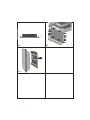
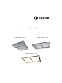
Instruction manual forCEILINGHOODS
Model code: CE1500
Model code: CE1100
Model code: CE1105
Contact Caple on 0844 800 3830 or for spare parts www.4caple.co.uk
2
GB
CONTENTS
Warnings
Uses
Installation
Working
Maintenance
3
another device ensuring omnipolar disconnections from the grid, with an opening distance between the contacts of at least 3 mm,
then such disconnecting devices must be
supplied within the fixed installation.
WARNINGS
The appliance is not intended for use by
young children or infirm persons without
supervision. Young children should be supervised to ensure they do not play with
the appliance.
If the appliance is endowed with a supply cord
and a plug, the appliance has to be put in a
place where the plug can be reached easily.
The use of materials which can burst into
flames should be avoided in close proximity of the appliance. When frying, please
pay particular attention to fire risk due to
oil grease. Being highly inflammable, fried
oil is especially dangerous. Do not use uncovered electric grills. In order to avoid
possible fire risk, all instructions for grease-filter cleaning and for removing eventual grease deposits should be strictly followed.
The air sucked canʼt be conveyed through or into a duct used to let out fumes
from appliances fed by energy other than
electric power (eg. centralized heating, radiators, water-heaters, etc.).
To evacuate the air outlet, please comply
with the pertaining rules given by competent authorities.
Provide the room with an adequate aeration
when a cooker hood and appliances fed by
energy other than electric power (gas-, oil-,
or coal- stoves, etc.) are used simultaneously.
The cooker hood, when evacuating the sucked
air, could generate a negative pressure in the
room- which canʼt exceed the limit of 0.04
mbar, in order to avoid the suck of exhausts
deriving from the heat-source. Therefore the
room should be provided with air-intakes to
allow a costant flow of fresh air.
USES
CE1500 - CE1100 - CE1105 with external
motors manufactured by the same producer.
PANELS OPENING
In CE1500, CE1100 models it is possible to
open the steel panels, which cover the grease
filters, by slightly pulling on a side of the panel itself, as shown in Fig. 3.
If the rating lable in the cooker-hood shows
the symbol
, the appliance is built in class
II° and it does not need any earth connection.
In CE1105 model, to open the panels you
need to push the appropriate hooks placed
on the sides of the panel , as shown in Fig. 11
and then rotating the panel downwards.
If the rating lable in the cooker-hood does
not show the symbol
, the appliance is
built in class I° and it needs the earth connection.
To achieve the complete opening of panels,
you need to release the safety chains, by
using the appropriate spring catches.
When performing the electrical connections
on the appliance, please make sure that the
current-tap is provided with earth connection
and that voltage values correspond to those
indicated on the label placed inside the appliance itself.
Before carrying out any cleaning or maintaining operations, the appliance needs to be
removed from the electric grid.
If the appliance is not provided with a nonseparable flexible cable and plug, or with
4
For proper working, it is recommended to install the appliance at a distance of 2000
- 2100 mm from the floor.
Before starting the appliance installation,
please check that all components are not damaged,
in such a case contact your retailer and do not
carry out installation.
INSTALLATION
CE1500 - CE1100 - CE1105
Fit a false ceiling with an opening of the following sizes:
Furthermore, please read carefully all of the
following installation instructions.
- Use an exhausting pipe whose maximum
length does not exceed 5 meters.
- Limit the no. of elbows in the piping, since
each elbow reduces the air capacity
of 1 linear meter. (Ex.: if you use no. 2 x 90 °
elbows, the length of piping must not exceed
3 meters).
- Avoid abrupt direction changes.
- Use a 150 mm constant diameter pipe for
the whole length.
- Use piping approved by standards in force.
CE1500: 1465x965 mm with a minimum distance of 270 mm between the ceiling and
the false ceiling;
CE1100: 1065x665 mm with a minimum distance of 270 mm between the ceiling and
the false ceiling.
CE1105: 1050x645 mm with a minimum distance of 250 mm between the ceiling and
the false ceiling;
It is possible to select the side of the hood
where the air suctioned can be discharged.
After having chosen the most suitable position, prepare the ducting: an air outlet connection piece, with a diameter of 150 mm to
be installed in the side selected, is provided
with the appliance.
Leave any unused exhaust outlets closed.
Draw the outline of the hole to house the ceiling-mounted hood on the solid ceiling (Fig.
1), according to the model chosen; make 4
holes in the ceiling according to the dimensions shown in (Fig. 2); place the metric plugs
provided in the holes.
Open the stainless steel panels, following
the instructions mentioned in the USES section, and remove the grease filters in order
to avoid damaging them in any way and too
allow installation (Fig. 3); screw the threaded bars provided into the plugs (Fig.4); the
threaded bars are 250 mm long and serve to
install the ceiling-mounted hood at a distance from the solid ceiling of between 270 mm
and 370 mm (Fig. 5); If the hood is installed
with lateral air outlet, fit a false ceiling with
an opening that has a minimum gap of 210
mm between the ceiling and the false ceiling
(Fig. 12); in case of a larger gap between the
hood and the ceiling, you need to use longer
threaded bars.
5
Make the electrical connections and connect
the air outlet pipe; place the ceiling-mounted
hood into the niche, by inserting the threaded
bars into the holes (Fig.6); the outer edge of
the hood needs to be perfectly flush with the
false ceiling. Insert the plates and nuts provided into the threaded bars, making sure to
tighten them securely (Fig. 7); refit the grease
filters and filter cover panels.
WORKING
6 - channel radio control for cooker hood remote (fig. 10).
Technical data:
Alkaline battery powered: 12v mod. 23A
Operating frequency: 433.92 Mhz
Combinations: 4096
Max. consumption: 25mA
Operating temperature: -20° : +55°C
- To light the cooker hood on or to
light it off press the button:
- To increase the speed up to the
fourth one press the button:
- To reduce the speed up to the
second one press the button:
- To go from a high speed back to
the first one press twice the button:
- To give power to the lights or to
shut them down press the button:
The “light” switch can turn the lights on and
off. after the first touch of the light switch the
lamps turn on at the maximum power. Keeping the switch pressed the intensity of the
light decreases and then increases continuously. Leaving the switch the brightness remains set up. Touching again the light switch
it is possible to turn the lamps off.
- To set the timer up press the
button:
The LED on the right side will start to flash
(every 5 seconds), the hood will work for 10
minutes at the selected speed and then it lights automatically off. If the client increases
or reduces the speed while the timer is on,
this is automatically stopped.
6
Standard configuration
If two cookerhoods-radiocontrol system are
installed in the same room or in the immediate
vicinity, each system may affect the operation
of the other, due to the fact that they have the
same code. Therefore it will be necessary to
change the code of one of the radio controls.
MAINTENANCE
An accurate maintenance guarantees good
functioning and long-lasting performance.
Warning:
The battery should be replaced every yearto guarantee the optimal range of
the transmitter. To replace the exhausted
battery, take the plastic lid off, remove the
battery and replace it with a new one, observing the correct battery polarities. Used
batteries should be discarded in special
collection bins.
A special care must be paid with grease filters: to remove the grease filter please follow
the instructions given in the ʻUSESʼ section ,
according to the model chosen.
Remove the grease filter by pulling its handle.
To reinsert the grease filter after the cleaning,
just perform the opposite operation.
Attention: after refastening the stainless steel
panel make sure that it is properly fixed.
Generating a new transmission code
The radiocontrol is supplied by the manufacturer with default codes stored. If you want to
create a new set of codes, proceed as follows:
press and hold the UP, STOP and DOWN buttons simultaneously for 2 seconds. Afterthe
LEDS light up, press the UP and DOWN button
swithin 5 seconds. The LEDS will flash 3 times
to indicate that the process is completed.
WARNING: This procedure deletes all previously stored codes.
To clean the appliance itself tepid water and
neutral detergents are recommended, while
abrasive products must be avoided.
For steel appliances specialized detergents are recommended (please follow the instructions mentioned on the product itself to
obtain the desired results).
To replace the lamp, (CE1500 - CE1100) remove the lamp (Fig. 9) and replace it with a
lamp of the same kind.
Learning the new transmission code
After changing the transmission code on the
radio control, the cooker hood electronic control unit must be made to set the new code
as follows: press the main Power Off button
on the cookerhood (fig. 8) and then restore
power to the electronic control unit. Within
the next 15 seconds, press the Light button.
This will ensure the control unit is synchronized with the new code.
To replace the fluorescent lamps (CE1105)
you need to disconnect the appliance from
the electrical network, then open the panel
following the instructions given in the ʻUSESʼ
section.
Remove the perimeter screws shown in fig.
13; pull the fluorescent lamps support out
(fig.14), and replace the old lamp with a new
one of the same kind.
Refit the panel and the screws previously removed.
To replace the fluorescent lamps ballast please follow the steps described above.
7
3
1
CE1100
CE1500
CE1105
4
2
5
8
6
7
8
9
10
11
9
13
12
14
10
11
90095000422 - GM 11/11