1
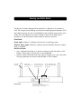
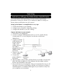
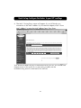
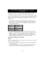
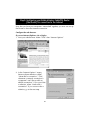
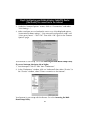
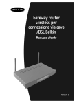
Belkin Wireless
Cable/DSL
Gateway Router
User Manual
F5D6230-3
Table of Contents
Introduction . . . . . . . . . . . . . . . . . . . . . . . . . . . . . . . . . . . . . . . . . . . . . . . . 1-3
Knowing your Belkin Router . . . . . . . . . . . . . . . . . . . . . . . . . . . . . . . . . . . . 4-5
Quick Setup
Setting up Your Belkin Wireless Cable/DSL Router
....................6
Configure your computers' networking settings. . . . . . . . . . . . . . . . . . . . . . . . 7
Configure the Router to your ISP’s settings . . . . . . . . . . . . . . . . . . . . . . . . 8-10
General Setup
Getting Started . . . . . . . . . . . . . . . . . . . . . . . . . . . . . . . . . . . . . . . . . . . . . . 12
STEP 1: Obtain information about your Internet Service
Provider (ISP) and your network . . . . . . . . . . . . . . . . . . . . . . . . . . . . . . . 13–19
STEP 2: Connect your computers to Router . . . . . . . . . . . . . . . . . . . . . . 20-22
STEP 3a: Setup your computers for networking . . . . . . . . . . . . . . . . . . . 23–32
STEP 3b: Setting up Wireless Computers for Connection to the Router . . 33-34
Step 4: Configuring your Belkin Wireless Cable/DSL Router
(the Router) for connection to the Internet . . . . . . . . . . . . . . . . . . . . . . . 35-46
Wireless Configuration . . . . . . . . . . . . . . . . . . . . . . . . . . . . . . . . . . . . . . 47-48
Other Features . . . . . . . . . . . . . . . . . . . . . . . . . . . . . . . . . . . . . . . . . . . . 49-55
Wireless Networking Using 802.11b . . . . . . . . . . . . . . . . . . . . . . . . . . . .56-59
Glossary of Wireless Networking Terms . . . . . . . . . . . . . . . . . . . . . . . . . 60-61
Glossary of Wired Networking Terms . . . . . . . . . . . . . . . . . . . . . . . . . . . 62-63
Troubleshooting . . . . . . . . . . . . . . . . . . . . . . . . . . . . . . . . . . . . . . . . . . . 64-66
Information . . . . . . . . . . . . . . . . . . . . . . . . . . . . . . . . . . . . . . . . . . . . . . 67-69
Introduction
Thank You for purchasing the Belkin Wireless Cable/DSL Gateway
Router (the Router). In minutes you will be able to network your
computers and share your Internet connection. The following is a list
of features that make your new Router an ideal solution for your home
or small office network.
Key Features
Integrated Wireless 802.11b Access Point
Wide Area Coverage at High Speeds
The Belkin Wireless Access Point provides coverage over an indoor area
up to 300 feet in radius and an outdoor area over 1800 feet in radius.
Up to 128-bit Security Encryption
Your Router is capable of encrypting (scrambling) the transmitted
radio waves so you can be sure that your data is secure. This optional
feature allows you to encrypt at 64-bits or 128-bits using a key that
you enter yourself.
Web-Based User Interface
Setting up the Router’s functions is done through your web browser. You
can do this easily without having to install additional software onto the
computer. There are no disks to install or keep track of and, best of all,
you can make changes and perform setup functions from any computer
on the network quickly and easily.
NAT Firewall Security
Your Router employs Network Address Translation (NAT) to protect your
network from the outside world by isolating it from the Internet. NAT
monitors all of the data coming in from the Internet and will only let
through the information you want.
Integrated 10/100 3-Port Switch
The Router has a built-in, 3-port network switch to allow your wired
computers to share printers, data and MP3 files, digital photos, and much
more. The switch features automatic detection so it will adjust to the
speed of connected devices. The switch will transfer data between
computers and the Internet simultaneously without interrupting or
consuming resources.
1
Introduction
Built-in DHCP Server
Dynamic Host Configuration Protocol (DHCP) on-board makes for the
easiest possible connection of a network. The DHCP server will assign IP
addresses to each computer automatically so there is no need for a
complicated networking setup.
MAC Address Filtering
For added security, you can set up a list of Media Access Control (MAC)
addresses (unique client identifiers) that are allowed access to your
wireless network. Every computer equipped with a wireless network
adapter has its own MAC address. Simply enter these MAC addresses into
a list using the web-based user interface and you can control access to
your network.
Applications and Advantages
• Wireless roaming with a laptop around the home or office
Offers the freedom of networking—without cables.
• Difficult-to-wire environments
Enables networking in buildings with solid or finished walls, or open
areas where wiring is difficult to install.
• Frequently changing environments
Adapts easily in offices or environments that frequently rearrange or
change locations.
• Temporary LANs for special projects or peak time
Sets up temporary networks such as at trade shows, exhibitions and
constructions sites, which need networks on a short-term basis—Also
companies who need additional workstations for a peak activity period.
• SOHO (Small Office/Home Office) networking needs
Provides the easy and quick small network installation SOHO users need.
2
Introduction
Package Contents
•
•
•
•
Belkin Wireless Cable/DSL Gateway Router
Power Supply
Belkin SOHO Networking Software CD
User Manual
System Requirements
• Broadband Internet connection such as a cable or DSL modem with
RJ45 (Ethernet) connection
• At least one computer with an installed wired or wireless network
interface adapter
• TCP/IP networking protocol installed on each computer
• CAT5e networking cable (or better)
• Microsoft Internet Explorer 4.0 or later, or Netscape 4.0 or later
3
Knowing your Belkin Router
The Router has been designed to be placed on a desktop or mounted to a
wall. The unique vertical design minimizes the desktop space required. All of
the cables exit from the rear of the Belkin Router for better organization and
utility. The LED indicators are easily visible on the front of the Router to
provide you with information about network activity and status.
Front Panel
Ready Light—When lit, indicates that the unit is receiving power.
Wireless Status Light—When lit, indicates that the Wireless Router’s wireless
radio is enabled.
WAN Link Status
• Link—indicates that there is an active connection with the cable or DSL
modem. If this light is off, the link is not established.
• Activity—When the WAN link status light is flashing, this means that data
is flowing between the Router and the cable or DSL modem.
Adjustable
Antennas
Front Panel
Ready Light
Indicates the power
is on or off
Wireless Status Light
Provides the status of
the Wireless LAN
Port Activity/Status Lights
Provide information about
the network
WAN Link Status Light
Provides information about the connection to the cable or DSL modem
4
Knowing your Belkin Router
Manual Reset
Used to reset the Router and
restore all factory defaults
Rear Panel
LAN Ports
Connect your PCs to these ports
WAN Port
Connect your cable or DSL
modem to this port
DC Power Jack
Connect the included power
supply to this jack
Port Activity/Status Lights
• Link—Solid indicates that there is a link between the Router and the
computer connected to that port.
• Activity—When an activity light is flashing, data is flowing between the
Router and the computer connected to that port.
Rear Panel
Power Input Jack—Connect 5V DC power supply.
WAN Port—Connect the network cable from the cable or DSL modem to
the WAN port.
LAN Ports—Numbered 1–3. Connect the network cable from your PCs to
these ports. Note: the computers do not need to be connected sequentially.
For example, in a two-computer network you can connect one computer to
Port 3 and another to Port 1.
5
Quick Set up
Quick Set up–Setting up Your Belkin Wireless Cable/DSL Router
If you are familiar with networking, you can use this Quick Setup
procedure to setup your Router. If you need more detail to setup your
Router, please read further into this manual.
Setting up the Router is accomplished in 3 easy steps
1. Connect the Router to your network.
2. Configure your computers' networking settings.
3. Configure the Router to your ISP’s settings.
Connect the Router to your network.
1. Power down your equipment.
2. Connect a network cable between each of your PCs and the Router.
Connect each PC to one of the ports on the rear of the Router
labeled LAN.
3. Connect a network
cable between the
Router and your
cable or DSL
modem. Be sure
this cable is
plugged into the port
labeled “WAN” on
the Router.
4. Power on the cable
or DSL modem.
5. Connect the
power adapter to
the Router.
6. After the cable or DSL modem and the Router are turned on, the Router’s
WAN link light should be on. This indicates that the modem and the
Router are connected to each other.
7. Turn on the rest of your computers. After your computers boot up, a LAN
link light (on the front of the Router) will be on for each port to which a
wired computer is connected. These lights are your means to verify that
your computers are connected.
6
Quick Set up–Configure your computers' networking settings
1. Configure the TCP/IP settings on your computers to obtain an IP address
automatically. The Router will use DHCP to assign each computer an IP
address in the range of 192.168.2.x.
2. Restart each computer and verify the network connection. Using the
“Network Neighborhood” or “My Network Places”, be sure that you can
view each connected machine.
7
Quick Set up–Configure the Router to your ISP’s settings
1. Using the computer that was originally connected directly to the cable or
DSL modem, launch your browser. Note: You can access the setup utility
from any computer on the network, however, use the original computer
for this procedure at this time.
2. In the address bar, type the following address: 192.168.2.1. The Router
login screen will appear.
If this is the first time you are accessing the Router, or you have not set
a password for the Router, there is no need to enter a password.
Click “Login”.
8
Quick Set up–Configure the Router to your ISP’s settings
3. The Router’s status page will appear.
4. Click on “Initial Setup” in the top left-hand corner. The following page
will appear.
5. Select your connection type (this information is provided by your ISP) and
click “Select”. Depending on your selection you will see the “Static IP
Address” page or the “PPPoE” page. Enter the required values provided
by your ISP and click “Enter”.
9
Quick Set up–Configure the Router to your ISP’s settings
6. The MAC Cloning/Entry screen will appear. If your ISP binds your
connection to the MAC address of your network adapter, click “Clone
MAC Address” or enter the MAC address here. Press Enter.
Your Router has been set up to communicate with your ISP. You should have
Internet access at this point. If you are having trouble, see the
troubleshooting section at the end of this manual.
10
General Setup
Getting Started
Your Router can connect a combination of wired and wireless computers
to the Internet while allowing for file and peripheral sharing. Setting up
wired and wireless connections to the Router is very easy to do. The
following steps will show you how to connect your computers to the
Router for networking and Internet sharing.
Sharing your Internet connection is done in 4 easy steps
Step 1:
Obtain information about your Internet Service Provider (ISP)
and your network
Step 2:
Connect your wired computers to the Router
Step 3a: Set up your computers for networking
Step 3b: Set up your wireless computers to connect to the Router
Step 4:
Configure the Router to connect to the Internet
12
STEP 1: Obtain information about your Internet Service
Provider (ISP) and your network
Setting up your Router is a simple procedure, even if you are not familiar
with networking. This guide will take you step by step through to the
setup process for successfully sharing your Internet connection. There are
a few pieces of information that you will need to obtain about your Cable
or DSL provider as well as about your network. Most of the time,
information is available online from your provider. You may have to call
your provider.
Answer the following questions either by checking with your ISP’s online
technical support or by calling your ISP’s technical support hotline. A
worksheet has been provided in this manual to record your information
for use later.
Is my IP address Static or Dynamic?
Your IP address is either static or dynamic. You will need to determine
whether your provider assigns you a new IP address every time you log
on (dynamic) or they assign you an IP address that never changes (static).
For more about what an IP address is, see the Glossary of Networking
Terms in the appendix of this manual.
Does my Internet service provider use PPPoE?
It either does or does not. If you have a DSL modem, your service
provider may use PPPoE (for Point to Point Protocol over Ethernet) as the
communication language between your DSL modem and the provider’s
network. If your DSL provider gave you software that you use to connect
to your Internet account, such as WinPOET, Enternet300 or any other
software that you need to run to connect to the Internet, then your service
provider uses a PPPoE connection. Follow the directions in this manual to
configure your router for PPPoE. For more about PPPoE, see the Glossary
of Networking Terms in the appendix of this manual.
13
STEP 1: Obtain information about your Internet Service
Provider (ISP) and your network
Is my connection bound to a MAC address?
It either is or is not. All network cards or adapters have a unique “serial
number”, called a MAC address. Your service provider can “see” your
network adapter's MAC address over the internet. In some cases, the
provider will record the MAC address of your network adapter and only
let that adapter connect to the Internet. This is done for several reasons,
one of which is security. It also enables your provider to keep track of
how many computers you have connected to your modem. You will need
to find out whether your provider requires the same network card to
connect to the modem all of the time. In the event that your provider does
bind your MAC address, your Router has a feature that will copy the MAC
address of your card. This will be covered later in the setup procedure.
For more about what a MAC address is, see the Glossary of Networking
Terms in the appendix of this manual.
Does my connection have an assigned Host Name?
It either does or does not. You will need to know if your provider assigns
you host name that is required for connection. If it does, then you will
need to know the Host name. If your computer was assigned a host name
by your provider, the next section describes how you can obtain your
host name.
14
STEP 1: Obtain information about your Internet Service
Provider (ISP) and your network
Setup Worksheet
My IP Address is:
Static
Dynamic
If your IP address is static, you need the following information:
Static IP address:
Assigned by your provider
Subnet Mask:
Assigned by your provider
Gateway:
Assigned by your provider
My provider binds my
connection to a MAC address
Yes
No
My provider has assigned me
a Host Name
Yes
No
Yes
No
If Yes, My Host Name is:
My provider uses PPPoE
If your provider uses PPPoE, you need the following information:
User Name:
Assigned by your ISP
[email protected]
Password:
Assigned by your ISP
Service Name:
Assigned by your ISP
not always necessary
15
STEP 1: Obtain information about your Internet Service
Provider (ISP) and your network
IMPORTANT:
IF YOU HAVE A CABLE OR DSL MODEM CONNECTED TO A PC AND
ARE NOW ADDING THE ROUTER TO YOUR NETWORK, FOLLOW
THESE STEPS TO OBTAIN INFORMATION YOU WILL NEED LATER.
If you are not connecting the Router to an existing cable or DSL modem,
skip to the next section called “Connecting the Belkin Wireless Router”.
Users of Windows 98 or Me can get the configuration information by
performing the following steps.
1. Turn on your computer and connect to the Internet through your cable or
DSL Modem.
2. In Windows 95, 98 and Me, Click “Start” then click
on “Run”.
3. In the Run dialog box, type “winipcfg” then click “OK”.
4. The IP Configuration window will appear.
5. In the drop-down menu, select your current Ethernet adapter by clicking
once on the down-facing arrow and highlighting your adapter’s name by
clicking on it once.
16
STEP 1: Obtain information about your Internet Service
Provider (ISP) and your network
6. The IP configuration window will appear. Click on
“More Info”.
7. This window will provide you with the Adapter Address (also known as
the MAC address), the IP Address, Host name (if any) and other network
settings. Carefully write this information in the table below, as you may
need it later for setting up the Router. For further explanation of what
these setting are, see the Glossary of Network Terms in the Appendix of
this manual.
17
STEP 1: Obtain information about your Internet Service
Provider (ISP) and your network
Users of Windows NT or Windows 2000 can get the configuration
information by performing the following steps.
1. Click “Start” then “Run” in the Run dialog box, type “CMD”.
2. In the “Command Window”, type “ipconfig /all”.
18
STEP 1: Obtain information about your Internet Service
Provider (ISP) and your network
3. The information pictured below should appear.
Please record your information in the chart below. It is important to make
sure you have it, in case something goes wrong.
Write your IP Configuration settings here:
Host name (If any):
Adapter Address:
IP Address:
Subnet Mask:
Default Gateway:
19
STEP 2: Connect your computers to Router
Connecting Wired Computers to the Router
Up to three wired computers can be connected directly to the Router. In
order for you to be able to connect your wired computers to the Router,
each must be equipped with a network interface card (NIC) such as an
internal PCI card (for desktop computers), a PC card (for laptop
computers) or a USB Ethernet adapter (an alternative for USB-equipped
computers only). Each computer connects to the Router via a network
cable. You will need one network cable for each PC. The Router also
connects to your cable or DSL modem via a network cable. Be sure you
have the proper parts before starting. NOTE: Some cable or DSL modems
connect to your computer using USB. Your cable or DSL modem must
have an Ethernet connector on it to connect the Router. If your modem
does not have an Ethernet connection, you must use a Belkin 5- or 8-Port
Network Switch rather than the Router.
Connecting Wireless Computers to the Router
Wireless computers can directly access the router once the Router and
your computers have been properly configured to do so. First, follow the
steps to connect your modem to the Router, then skip to section “Step 3b:
Setting up Wireless Computers for Connection to the Router”, on page
32, following.
Connect Your Equipment
Refer to the diagram below to aid in the connection process. Before
beginning, please note that the connection process involves powering
down your equipment and then powering it back up in correct sequence.
It is important that the equipment is powered on in the following order:
modem first, Router second, computers last. Failure to follow this
sequence may cause the network to fail to work properly.
1. Power down your equipment.
Make sure that you have followed the steps to find your network
configuration settings before you begin connecting your equipment. Be
sure that the power to the Router, your modem, and all of your
computers has been turned OFF.
20
STEP 2: Connect your computers to Router
2. Connect a Belkin CAT5 Network Cable between each of your wired
computers and the Router.
Plug in a CAT5 network cable to the Ethernet port on each of the
other PCs and then to one of the ports labeled "LAN" on the rear of
the Router.
Note: It does not matter which LAN ports you connect your other
computers to, but be sure that you are not connecting any of the
computers to the port labeled "WAN".
3. Connect a Belkin CAT5 Network Cable between the Router and your
cable or DSL modem.
Plug in another cable to the port labeled "WAN" on the Router and
connect the other end of the cable to the cable or DSL modem’s
Ethernet port.
21
STEP 2: Connect your computers to Router
4. Power on the cable or DSL modem.
Depending on your modem, it may have a power switch or you may
have to plug the power supply into it. Be sure that the modem is
turned on before the Router is turned on.
5. Connect the power adapter to the Router.
Connect the power supply to the router to turn the router on. Again,
be sure the modem is powered on before powering on the Router.
6. After the cable or DSL modem and the Router are turned on, the
Router’s WAN link light should be on. This indicates that the modem
and the Router are connected together.
7. Turn on the rest of your computers and let them boot up. After your
computers boot up, the LAN link lights on the front of the Router
should be on for each port to which a computer is attached. Verify
that your computers are connected by checking these lights.
Connection of your Router is now is complete. The next step is to set up
each of your computers to be able to communicate with your Router.
Go to Step 3.
22
STEP 3a: Set up your computers for networking
If you are familiar with setting up TCP/IP and file sharing on your
computers, it is not necessary to use the Belkin SOHO Networking
software. Each computer should be set up to "Obtain IP address
Automatically (PC)" or use "DHCP (Mac)". Enable printer and file sharing
on each computer if you wish to share resources.
Mac users, skip to the portion of this section that covers Mac computers.
(see page 31)
If you are not familiar with setting up TCP/IP and file sharing on your PC,
Belkin has simplified the process by providing you with the Belkin SOHO
Networking software to configure your Windows 98 or Me computers.
Follow the steps below to install this software on your computers.
Windows 2000 users, follow the step called Configuring Network Settings
for Windows 2000.
Installing the Belkin SOHO Networking Software on your PC on your
Windows 98/Me PC (Optional)
The SOHO networking software can be used to set up the networking
setting on both wired and wireless-equipped computers. This software will
allow you to configure network setting under Windows 98 and Me. If you
are using Windows 2000 or XP, the SOHO networking will prompt you to
launch the Network Control Panel. Use of the Belkin SOHO Networking
Software is not necessary to configure your computers.
1. Insert the CD-ROM that came with the Belkin Wireless Cable/DSL
Gateway Router into your CD-ROM drive of your computer
connected to LAN Port-1.
2. Click “Start” then click “Run”. Type “D:\NetSetup”, where D:\ is the
drive letter of your CD-ROM drive.
3. Click “OK”. Windows will install the software onto your PC. Follow
the directions on the screen to complete the installation. After the
Belkin SOHO Networking Software is installed, Windows may ask
you to restart your computer. If it does, please do.
23
STEP 3a: Set up your computers for networking
4. Repeat these steps for each computer you are connecting to
your network.
5. Once you have installed the Belkin SOHO Networking Software on
all of your computers, continue on to the next section.
Configuring Your PCs Using Belkin NetSetup (Win 98/Me)
1. Once your computer has restarted, click “Start”, “Programs”, “Belkin
SOHO Networking” then “Belkin NetSetup” to launch this easy-touse computer configurator. The following screen will
appear: Select “I am setting up the Belkin Gateway Router” and
click “Next”.
2. The following screen will appear: Select “I am setting up the first
computer in my network” and click “Next”.
24
STEP 3a: Set up your computers for networking
3. The following screen will appear:
4. In the “Computer Name” field type a name for the computer such as
“Computer 1”. The name must be different for each computer on
the network.
5. In the “Workgroup” field, type a workgroup name such as “My
Network”. The workgroup name must be the same for each computer
on the network.
6. The description field helps to identify the computer further. Type in a
description such as “Windows 98”. This description can be anything
you want. It is not necessary for it to either match or be different from
the description of any other computer on the network. You may also
leave this field blank.
25
STEP 3a: Set up your computers for networking
7. After entering the information in the three fields, click “Next”. The
following screen will appear:
8. If you want to share files and printers on this computer, select “I want
to share files and printers on my computer” and click “Finish”. The
following screen will appear:
26
STEP 3a: Set up your computers for networking
9. NetSetup now needs to now if you want to create a client setup floppy
disk. If you have more computers than you need to setup to work with
the Router, click “Yes”. This will save some files to the disk that your
other computers can use to make setup easier. If you are not going to
setup any more computers, click “No” and skip to step 11.
10. If you clicked “Yes”, you will be prompted to insert a floppy disk into
the PC’s floppy disk drive. Label a floppy disk “Belkin Networking
client setup disk” or something else that you will remember easily and
insert it into the floppy disk drive. Click “OK.”
11. After the client setup disk has been created, you will be prompted to
restart your computer. Please restart your computer.
Configuring Additional Computers Using Belkin NetSetup Software
(Win 98/Me)
Now that the first computer has been configured you are ready to
configure the other PCs on your network.
1. You should now be working with the next computer. Click “Start”,
“Programs”, “Belkin SOHO Networking” then “Belkin NetSetup” to
launch the easy-to-use computer configurator. The following screen
will appear:
27
STEP 3a: Set up your computers for networking
2. Select “I am adding this computer to my network”. Click “Next”.
3. Windows will now prompt you to insert the newly created client disk
into the PC’s floppy drive. Insert the disk you labeled “Belkin
Networking” into the floppy drive and click “OK”. The following
screen will appear:
4. In the “Computer Name” field type a name for the computer such as
“Computer 2”. Remember, the name must be different from the other
computers on the network.
5. The workgroup name should be filled in with the name you entered on
the previous computer. Do not change this setting.
6. Type in a description such as “Windows 98”. This can be anything you
want and does not have to be different or the same as any other
computer on the network. You may also leave this field blank.
28
STEP 3a: Set up your computers for networking
7. When finished filling in the fields, click “Next”. The following screen
will appear:
8. If you want to share files and printers on this computer, select “I want
to share files and printers on my computer” and click “Finish”. If not,
select “I do not want to share files and printers on my computer”.
Click “Finish”.
9. Now, please restart the computer.
10. Your PC is now configured. Repeat these steps for the rest of the
computers on your network.
29
STEP 3a: Set up your computers for networking
Configuring Network Settings for Windows 2000
1. Right-click on “My Network Places” and select “Properties”.
2. In the “Network and Dial-up Connections” window, your “Local Area
Connection” should be available.
3. Right-click on “Local Area Connection” and select “Properties”.
4. Highlight “Internet Protocol (TCP/IP)” and click on “Properties”.
30
STEP 3a: Set up your computers for networking
5. Select “Obtain IP address automatically” and “Obtain DNS server
address automatically”. Click “OK”. Windows may ask you to restart
the computer. Do so to finish configuring your network settings.
Configuring Network Settings on your Mac
1. Pull down the Apple Menu. Select “Control Panels” and select
“TCP/IP”.
2. At “Connect Via:” choose either “Ethernet Built In” or “Ethernet” based
on your Mac’s interface.
3. At “Configure”: choose “Using DHCP Server”. This will tell the
computer to obtain an IP address from the Router.
31
STEP 3a: Set up your computers for networking
Mac Continued
4. Close the window. The following window will appear. Click “Save”.
5. Restart the Computer.
The last thing you need to do is set up the Belkin Wireless Cable/DSL
Gateway Router to work with the Internet. To learn how to do this, go
to Step 4.
32
STEP 3b: Setting up wireless computers for connection
to the Router
This step assumes that you already have a wireless adapter installed on
the computer(s) that you wish to connect wirelessly to the Router.
To connect to the Router wirelessly, you must set your computer’s wireless
settings to the same settings as those on the Router. Your Router ships from
the factory with default settings for the SSID (ESSID), the Channel, and
the Encryption.
1. Set the wireless computer’s wireless configuration to match the Router’s
default settings. For information about changing these settings, refer to the
documentation of your wireless network adapter. Change the settings to
match the settings below:
Mode
Infrastructure
SSID
WLAN
Channel
11
Encryption
Disabled
2. If you have already set up your computer’s networking settings using the
Belkin SOHO Networking Software, skip this step. If not, either follow the
directions in Step 3a, or if you are familiar with TCP/IP and file and
peripheral sharing, configure the TCP/IP settings of the wireless adapter to
“Obtain IP Address Automatically” (PC) or “Use DHCP” (Mac).
Verify That Your Computers are Networked
Windows
Once you have set up all of your computers, you can check to see if they
are all “networked” together.
1. Starting with any computer, double-click on the “Network Neighborhood”
icon on your desktop.
2. You should see an icon in the Network Neighborhood window with the
name that you provided for your workgroup. Double-click this icon.
33
STEP 3b: Setting up wireless computers for connection
to the Router
3. You should now see an icon for each computer you set up for the network.
Please note, if the computers have just finished re-booting, it may take a
few seconds for the computers to appear in the window.
4. If all of the computers appear in the window, then you have successfully
networked your computers.
The last thing you need to do is set up the Belkin Wireless Cable/DSL
Gateway Router to work with the Internet. To learn how to do this, go
to Step 4.
34
Step 4: Configuring your Belkin Wireless Cable/DSL Router
(the Router) for connection to the Internet
Now that you have your computers “networked” together, you now can set up
the Router to share the Internet connection.
Configure the web browser
If you use Internet Explorer 4.0 or higher.
1. Start your web browser. Select “Tools” then “Internet Options”
2. In the “Internet Options” screen,
there are three selections called
“Never dial a connection”, “Dial
whenever a network connection is
not present” and “Always dial my
default connection”. If you can make
a selection, select “Never dial a
connection”. If you cannot make a
selection, go to the next step.
35
Step 4: Configuring your Belkin Wireless Cable/DSL Router
(the Router) for connection to the Internet
3. Under the “Internet Options” screen, click on “Connections” and select
“LAN Settings…”.
4. Make sure there are no checkmarks next to any of the displayed options;
“Automatically detect settings”, “Use automatic configuration script” and
“Use a proxy server”. Click “OK”. Then click “OK” again in the “Internet
Options” page.
Your browser is now setup. Go to the Accessing the Web Based Setup Utility.
If you use Netscape Navigator 4.0 or higher.
1. Start Netscape. Click on “Edit” then “Preferences”.
2. In the “Preferences” window, click on “Advanced” then select “Proxies”. In
the “Proxies” window, select “Direct connection to the Internet”.
Your browser is now setup with the Router. Go to the Accessing the Web
Based Setup Utility.
36
Step 4: Configuring your Belkin Wireless Cable/DSL Router
(the Router) for connection to the Internet
Accessing the Web Based Setup Utility
By now, you should have the information about your Internet Service
Provider written on the worksheet at the beginning of this manual. Please
have it handy as you go through this procedure. Your Router is equipped
with a setup utility that is ‘web-based’, which means that you will use
your Internet browser to do the setup. To access the Router’s setup utility
use your web browser (either Internet Explorer or Netscape Navigator).
1. Using the computer that was originally connected directly to the
Cable/DSL modem, launch your browser. When your browser
launches, it will attempt to find your home page. In some cases, the
router will be able to connect to the Internet without any further setup.
If your home page is displayed in the browser, then no further setup is
needed. You can begin surfing the net, or continue on to learn how to
configure the router.
If a message pops up in the browser stating that the page could not be
found, this is normal. Please go to the next step. Note: You can access the
setup utility from any computer on the network, however, use the original
computer for this procedure at this time.
2. In the address bar, type the following address: 192.168.2.1.
37
Step 4: Configuring your Belkin Wireless Cable/DSL Router
(the Router) for connection to the Internet
3. The Router login screen will appear.
If this is the first time you are accessing the Router or you have not set a
password for the Wireless Gateway Router, there is no need to enter a
password. Click “Login”.
4. The Router’s initial setup page will appear.
38
Step 4: Configuring your Belkin Wireless Cable/DSL Router
(the Router) for connection to the Internet
Dynamic Setup
Configuring Your Router if your Provider uses Dynamic IP Addressing
Follow this procedure if your ISP uses dynamic IP addressing. The Router's
default (factory) setting is set to dynamic. If your ISP has provided you
with a Static IP address or your provider uses PPPoE for you to connect
skip to the next section.
1. Click on “Initial Setup”. The following screen will appear:
2. Select “Dynamic IP Address” and click “Select”.
This will tell the Router that the ISP provides a dynamic IP address.
3. Click “MAC Cloning/Entry” on the left-hand side of the screen. The following
screen will appear.
39
Step 4: Configuring your Belkin Wireless Cable/DSL Router
(the Router) for connection to the Internet
4. If your ISP assigned you a host name, enter the host name here. If not, leave this
field blank.
5. If your ISP binds the connection to a MAC address, you will need the Router to
copy that MAC address. If your ISP does bind your MAC address, or you are not
sure, follow this step. Click “Clone MAC Address”. This will clone (copy) the
MAC address of the first PC connected to the Router. This will also ensure that
the ISP, if it binds your connection to that MAC address, that it will remain active.
Click “Enter” to save the settings.
Finishing Dynamic Setup
At this point, initial setup of the Router is now complete for a dynamic
configuration. To verify that your Router is connected to the modem, click
on “Status” in the lower left hand corner of the router setup page. The
status page shows you a variety of information about the Router’s current
state. Under the heading “INTERNET”, the connection status is displayed
as “Cable/DSL:” The word “Connected” will appear if the Router is
connected to the Internet, this indicates that initial setup was successful.
To begin browsing the Internet, log out of the setup utility by clicking on
the “Logout” button. Once you have logged out, type a web address such
as www.belkin.com into the browser’s address bar. The browser should
take you to the web address you entered. Other computers you have
connected to the router should also have access to the Web. If you are
having problems, see the troubleshooting section of this manual.
40
Step 4: Configuring your Belkin Wireless Cable/DSL Router
(the Router) for connection to the Internet
Static IP Setup
Configuring Your Router if your Provider uses Static IP Addressing
If your ISP uses Static IP Addressing, follow this procedure. If your
provider uses PPPoE, then skip to the next section.
1. Click on “Initial Setup”. The following screen will appear:
2. Select “Static IP Address” and click “Select”. The following
screen will appear:
3. Enter your static
IP address.
4. Enter your Subnet
mask.
5. Enter the Router
address.
6. Once you have
filled in all of this
information, click
“Enter”.
41
Step 4: Configuring your Belkin Wireless Cable/DSL Router
(the Router) for connection to the Internet
7. The“MAC Cloning/Entry” screen will now appear.
8. If your ISP assigned you a host name, enter the host name here. If not, leave
this field blank.
9. If your ISP binds the connection to a MAC address, you will need the
Router to copy that MAC address. If your ISP does bind your MAC address,
or you are not sure, click “Clone MAC Address”. This will clone (copy) the
MAC address of the first PC connected to the Router. This will also ensure
that the ISP, if it binds your connection to that MAC address, will remain
active. Click “Enter” to save the setting.
Finishing Static Address Setup
At this point, initial setup of the Router
is now complete for a static
configuration. To verify that your
Router is connected to the modem,
click on “Status” in the lower left hand
corner of the router setup page. The
status page shows you a variety of
information about the Router’s current
state. Under the heading “INTERNET”,
the connection status is displayed as
“Cable/DSL:” The word “Connected”
will appear if the Router is connected to the Internet, this indicates that initial
setup was successful.
42
Step 4: Configuring your Belkin Wireless Cable/DSL Router
(the Router) for connection to the Internet
To begin browsing the Internet, log out of the setup utility by clicking on
the “Logout” button. Once you have logged out, type a web address such
as www.belkin.com into the browser’s address bar. The browser should
take you to the web address you entered. Other computers you have
connected to the router should also have access to the Web. If you are
having problems, see the troubleshooting section of this manual.
PPPoE
If you have a DSL modem and your Internet Service Provider gave you
software such as WinPOET or Enternet300 that you use to connect to the
Internet, follow these steps to set up your Router for PPPoE.
1. It is recommended that you uninstall the software that your ISP
provided to you for connecting to the Internet. Before uninstalling the
software from your computer, be sure you have a copy of the software
in the event you want to re-install it at some point. If you do not
uninstall the PPPoE software provided to you by your ISP, your
connection may not work properly. To uninstall the software, Click on
“Start” then “Settings” then “Control Panel”.
43
Step 4: Configuring your Belkin Wireless Cable/DSL Router
(the Router) for connection to the Internet
2. The Control panel window will open. Double-click on
“Add/Remove Programs”
3. A list of programs installed on your computer will be displayed in the
window. Locate the PPPoE software that was provided to you by your
ISP and highlight it by clicking on it one time. Click the “Add/Remove”
button and follow the steps to complete the removal of the software.
4. Once you have removed the PPPoE software, go back to your browser.
Click on “Initial Setup” in the Router’s user interface. The following
screen will appear:
44
Step 4: Configuring your Belkin Wireless Cable/DSL Router
(the Router) for connection to the Internet
5. Select “PPPoE” and click “Select”. The following screen will appear:
6. Enter your User Name. Your user name is the name that you use to log
on such as “[email protected]”
7. Enter your Password.
8. Type your password
one more time to
confirm your
password was
entered correctly.
9. Enter your Service
Name. The service
name is not always
required. If you are
not sure or you do
not have a service
name, then leave
this blank.
10. Once you have filled in all of this information, click “Enter”.
11. Pressing “Enter will take you to the MAC/Cloning Entry page”. Your
setup is complete. Go to the next section called Finishing PPPoE Setup.
45
Step 4: Configuring your Belkin Wireless Cable/DSL Router
(the Router) for connection to the Internet
Finishing PPPoE Setup
At this point, initial setup of the Router is now complete for a PPPoE
configuration. To verify that your Router is connected to the modem, Click
on “Status” in the lower left hand corner of the router setup page. The
status page shows you a variety of information about the Router’s current
state. Under the heading “INTERNET”, the connection status is displayed
as “Cable/DSL :” The word “Connected” will appear if the Router is
connected to the Internet, this indicates that initial setup was successful.To
Browse the Internet
To begin browsing the Internet, log out of the setup utility by clicking on
the “Logout” button. Typically, to connect to your Internet Service you
would use the software that is provided by your ISP. With the Router now
in place, you do not need to use this software to connect to the Internet.
Simply type a web address such as www.belkin.com into the browser’s
address bar. If the Router is set up properly, the browser should take you
to the web address you entered. Other computers you have connected to
the router should also have access to the Web. If you are having problems
connecting, you may need to uninstall the software that was provided to
you by your ISP. If problems persist, see the troubleshooting section of this
manual or contact Belkin’s technical support hotline.
46
Wireless Configuration
Congratulations! You have successfully installed your Router. The further
sections in this manual explain more about the advanced features of your
Router. Please read through them to learn more about your Router.
Channel and SSID
From the Initial Setup page, click on “Channel and SSID”, under Wireless,
in the right side of the screen, to access the Channel and SSID page.
Channel
The 802.11b wireless standard supports up to 14 channels. The number of
available channels are limited to local regulations which determine which
channels are available. FCC/IC: Channels 1-11. ETSI: Channels 1-13,
France: Channels 10-13, Spain: Channels 10-11, MKK: Channels 1-14.
The default channel is 11. To change the channel, click the DOWN arrow
next to the channel field and select the channel number. When finished
making changes, click “Enter” for the changes to take effect.
SSID
The Service Set Identifier (SSID) is like a name for the wireless network
and is sometimes called the “Network Name”. The wireless-equipped
computers in the wireless network should be set to the same SSID to gain
access to the network. The default setting is “WLAN” (Wireless Local Area
Network (WLAN). To change the SSID, simply click in the SSID field and
enter a new SSID.
When finished making
changes, click “Enter”
for the changes to
take effect.
47
Wireless Configuration
Using WEP Encryption
From the Initial Setup page, click on “Encryption” under Wireless in the
right side of the screen to access the Encryption page. The default setting
for Encryption is “Disabled”.
Setting Encryption
Encryption requires a key on both the Router and the wireless-equipped
computer to match. Keys can be entered manually or automatically by
typing a passphrase. The easiest method is the use of a passphrase. To
Enable 64-bit manual encryption, select 64-bit manually from the menu.
You will notice when using 64-bit manual encryption there are 4 keys
labeled “Key 1” through “Key 4”. Only one key can be used at a time. In
manual mode, keys can be entered manually, but for ease of use, the
software can generate keys using a “Passphrase” that you enter. Select
“64-bit automatically” and enter a passphrase. This passphrase can be
easily distributed to wireless equipped computer users in your network.
For instance, creating a key using the passphrase “Passphrase” generates 4
keys in 64-bit encryption mode. 128-bit encryption mode uses only one
key. Keys can be manually entered or created with a passphrase. A user of
a laptop needs only to enter the passphrase and the key number (key
number for 64-bit only) into their computer’s wireless management
software to be able to communicate while using encryption. All
computers on the network must use the same encryption rate and
passphrase. The passphrase can be changed as often as desired.
48
Other Features
MAC Address Cloning
If your ISP binds the connection to a MAC address, you will need the
Router to copy that MAC address. If your ISP does bind your MAC
address, or you are not sure, follow this step.
1. Click “MAC Cloning/Entry”. The following screen will appear:
2. Click “Clone MAC Address”. This will clone (copy) the MAC address of
the first PC connected to the Router. This will also ensure that the ISP,
if it binds your connection to that MAC address, that it will remain
active. Click “Enter” to save the settings
3. Your Router is now set up and you will be able to access the Internet
from any PC on your network.
49
Other Features
MAC Filtering
MAC filtering lets you control access to the network by allowing or
disallowing specific MAC addresses to connect to the router. You can
enter a list of up to twenty MAC addresses into the Router. This list is
known as the Control List. By enabling MAC address control, then setting
connection control settings and association control settings, you can keep
your network more secure.
Connection control
Connection control lets you allow or deny connection to wired or
wireless computers trying to access the Router. Enable Connection control
by placing a checkmark in the box. Once you have entered a MAC
address into the control table, putting a checkmark in the box under “C”
will grant that computer full access to the network. Leaving the box
unchecked will let the computer access the network to communicate with
other wired computers, but that computer will not have Internet access or
be able to communicate with wireless computers on the network. The
“allow/deny” box lets you determine if computers with MAC addresses
NOT in the control table are allowed access to the network and all of the
resources such as Internet. Selecting “deny” will not let a computer
connect unless the MAC address is in the control table.
50
Other Features
Association control
Association control works much like connection control. It lets you allow
or deny connection to wireless computers trying to access the Router.
Enable Access control by placing a checkmark in the box. Once you have
entered a MAC address into the Control Table, putting a checkmark in the
box under “A” will grant that wireless computer full access to the
network. Leaving the box unchecked will let the computer access the
network to communicate with other wireless computers, but that
computer will not have Internet access or be able to communicate with
wired computers on the network. The “allow/deny” box lets you
determine if computers with MAC addresses NOT in the control table are
allowed access to the network and all of the resources such as Internet.
Selecting “deny” will not let a computer connect unless the MAC address
is in the control table.
Association control has no effect on wired clients.
Security
Intrusion Detection On/Off
To access this feature, click on “Firewall” on the left side of the screen.
The Router can monitor any attempts to access your network and alert
you when it happens. If you want this feature to work, select “Enable”.
Security Log
To access this log, click on “Security Log” on the left side of the screen.
The Router will record any unauthorized attempts that have been made
to gain access to your network. This screen will let you view a log of
these attempts.
51
Other Features
DMZ Settings
To access this feature, click on “DMZ” on the left side of the screen.
Demilitarized Zone (DMZ) is a feature that allows a computer to be
exposed to the Internet by “placing” it outside of the firewall. This feature
comes in handy when playing Internet games that don’t work well with a
firewall. Also, streaming video applications can benefit from bypassing the
NAT firewall security. To place a computer in the DMZ, enter the IP
address of the computer here. The Router supports one computer in the
DMZ. Please note that when a computer is not protected by the firewall it
is open to hacker attacks. Use this feature only when needed.
Virtual Server Settings
The Router can be
configured as a virtual
server. Your WAN interface
must use a fixed IP address
to utilize the virtual server
function. Using the virtual
server function will allow
clients accessing services
such as Web or FTP at
your local site via public
IP addresses to be
automatically redirected to
local servers configured with private IP addresses. In other words,
depending on the requested service (TCP/UDP port number), the Router
redirects the external service request to the appropriate server (located at
another internal IP address). For example, if you set Type/Public Port to
TCP/80 (HTTP or Web) and the Private IP/Port to 192.168.2.2, port 80,
then all HTTP request from clients will be transferred to 192.168.2.2.
Therefore, by just entering the IP Address provided by the ISP, Internet
users can access the service they need at the local address to which you
redirect them. Some of the more common TCP service ports include:
HTTP: 80, FTP: 21, Telnet: 23 and POP3: 110.
52
Other Features
Special Application Settings
Some applications require
multiple connections, such as
Internet gaming,
videoconferencing, Internet
telephony and others. These
applications may not work when
Network Address Translation
(NAT) is enabled. If you need to
run applications that require
multiple connections, use the
following screen to specify the additional public ports to be opened for
each application. Specify the port normally associated with an application
in the “Trigger Port” field, select the protocol type as TCP or UDP, then
enter the public ports associated with the trigger port to open them for
inbound traffic.
Note: If an application still cannot function correctly after enabling
multiple ports via the Special Application screen, you may have to open
the client PC for full Internet access using the DMZ Host option.
Client Filter Settings
Click on “LAN Client Restrictions”. The Router can be configured to
restrict Internet access to computers at specific days and times. For
example, to restrict web access to the client at IP address 192.168.2.15
enter “15” and “15” in the IP field.
Enter 80 (HTTP and Web) in the
Port field. Select TCP. Select Block.
Then select “Monday” and “Friday”
then select “8:00AM” to “5:00PM”.
Lastly, click “Enable” and then
click enter. Now the client at IP
address 192.168.2.15 will not
have Internet access from 8:00AM
to 5:00PM.
53
Other Features
Services
LAN DHCP Settings
Click on “LAN Services” to access this screen. Your Router allows you to
specify an internal IP address. You may also turn the DHCP service on
and off. We recommend using DHCP service for the easiest setup of your
network. Making changes to this screen will require you to re-configure
your networked PC's.
NAT Enable/Disable
Network Address Translation (NAT) is used for security by making your
internal network invisible to the Internet. We recommend that you leave
NAT enabled for security reasons.
Set Time Zone
If you are using any of the time-based functions of the Router such as
Client Filtering, you will need to set the time zone you reside in for the
function to work properly. Your Router automatically obtains the correct
time from the Internet by using SNTP (Simple Network Time Protocol).
There are many servers on the Internet which get the time from the atomic
clock. The time is then broadcast over the Internet from these servers and
then is received by your Router. You do not need to set the clock.
Change Password
The Router ships without a set password. It is not necessary to enter a
password. If you choose not to use a password, leave the space blank. If
you do choose to enter a password, be sure to write it down in a safe
place. To set a password, enter it into the "New Password" field and
confirm it in the next field. To change your password, enter your existing
password and then enter the new password twice. If you forget your
password, you can perform a manual reset of the router by pressing and
holding the reset button for 5 seconds. When you release the button, the
power light will begin flashing. Reset is done on the back of the Router.
54
Other Features
Remote Management
Any computer on your network can access the Router's built-in setup
utility. The Remote Management feature allows a computer outside of the
network to access the setup utility. When enabled, only the computer at
the specified IP address can access the setup utility. Entering 0.0.0.0 will
allow access by any computer.
Utilities
Access the Utilities screen
by clicking on “Utilities”.
Reset
If the Router stops
functioning properly, you
can reset or reboot the
Router via the browser
based software. Your
settings will not be lost
when performing a
software reset. To perform
a reset, click on the
RESET button. You will be
asked to confirm that you
want to reset the Router. The power light will begin blinking and the port
lights may blink. When the lights stop blinking, the Router has been reset.
Restore Defaults
To restore the factory default settings of the Router, click this link. All of
your settings will change back to the state they were in when the Router
initially shipped. Please be sure this is what you want to do before
clicking the Restore Defaults link.
Update Firmware
Belkin will create new firmware for your Router. Firmware updates
enhance performance and improve functionality.
55
Wireless Networking Using 802.11b
To form a wireless network, two basic components are used. The first is a
wireless adapter for a PC. This can be either a USB wireless adapter or a
PCMCIA adapter. The adapter gives the PC wireless Ethernet capabilities.
The second is a Wireless Access Point, which A can connect to a wired
LAN and allow the wireless PC’s to be able to access the wired LAN. A
Wireless Access Point can be a stand alone component or it can be
embedded into a Cable/DSL router, thus forming a wireless
Gateway/Router. The uses of each of these types of products is outlined
later in this article.
Wireless networking is very similar to wired networking, except for a few
basic concepts that one must grasp. There are two different ways to
network computers using 802.11b. The first, and least used method is the
Ad-Hoc method, also known as Peer-to-Peer. The more commonly used
method is called Infrastructure Mode.
Ad-Hoc (Peer-to-Peer) Network
Ad-Hoc or Peer-to-Peer refers to a wireless configuration in which each
computer communicates directly with another. An Ad-Hoc wireless LAN
consists of a group of computers, each equipped with a wireless adapter,
connected directly via radio signals to form an independent wireless LAN.
Computers in a specific Ad-Hoc wireless LAN must be configured to the
same radio channel to communicate with one another. More than one
Ad-Hoc network can exist in the same space if it is configured to operate
on a different channel. There are a varying number of channels depending
on which the part of the world you are operating in. The US has 11
channels, Europe has 13 channels and Japan has 14 channels. The
following diagram shows a typical Ad-Hoc wireless LAN configuration.
56
Wireless Networking Using 802.11b
Notebook with Wireless
Notebook Network Card
Notebook Wireless
Notebook Network Card
PC with Wireless Desktop PCI
Network Adapter
Infrastructure Mode
The use of a Wireless Access Point(WAP) to connect a wireless LAN to a
wired LAN is called the Infrastructure Mode. A WAP serves as a bridge
between the wired and wireless network. Connecting the Access Point to
any port on the wired network will give wireless access to all wirelessequipped computers within its coverage area. An access point is
configured with a Service Set Identifier, a “name” given to the wireless
network and used by the wireless-equipped computers to access the
wireless network. Access points can also be configured to use encryption
or they can grant access to computers with specific MAC addresses. They
effectively double the distance that computers in the wireless LAN can be
located from one another. This is because the unit serves as a central
point for routing of all the wireless network traffic between the wirelessequipped computers. Wireless-equipped computers networked together in
Infrastructure Mode form a group called a Basic Service Set (BSS). Up to
64 individual computers can exist at a single time in a BSS. This is due to
the ability of the WAP to handle no more than 64 clients. The diagram
below illustrates how the WAP works to increase the covered area range
of your wireless network.
57
Wireless Networking Using 802.11b
Notebook with Wireless
Notebook Network Card
WAP
Basic Service
Set (BSS)
Notebook Wireless
Notebook Network Card
PC with Wireless Desktop
PCI Network Adapter
The diagram below illustrates how an WAP acts as a bridge between the
wireless BSS and the wired network.
Desktop PC
Desktop PC
Switch
Notebook with Wireless
Notebook Network Card
Wireless
Access Point
Basic Service
Set (BSS)
PC with Wireless Desktop
PCI Network Adapter
58
Wireless Networking Using 802.11b
Roaming
More than one WAP can be used to increase the wireless coverage in a
wireless LAN. The diagram below shows two WAPs configured to extend
coverage beyond that of a single unit. The overlapping area of each BSS is
called and Extended Service Set (ESS). When a wireless computer enters
the ESS, the computer evaluates the signal strength and link quality, then
chooses the WAP with the best quality signal and link. This activity is
known as roaming. To configure your WAPs to allow roaming inside of
the wireless network, each unit will be assigned the same Service Set
Identifier (SSID). Strategically placing multiple units around an office or
inside of the home can extend the wireless coverage to the entire premise.
The illustration below shows two Basic Service Sets overlapping to form
an Extended Service Set.
Desktop PC
Desktop PC
Switch
BSS2
Wireless
Access Point
ESS
Wireless
Access Point
BSS1
59
Glossary of Wireless Networking Terms
Access Point- An internetworking device that seamlessly connects wired
and wireless networks.
Ad-Hoc - An Ad-Hoc wireless LAN is a group of computers each with
LAN adapters, connected as an independent wireless LAN.
Backbone - The core infrastructure of a network. The portion of the
network that transports information from one central location to another,
where it is unloaded onto a local system.
Base Station - In mobile telecommunications, a base station is the central
radio transmitter/receiver that maintains communications with the mobile
radiotelephone sets within its range. In cellular and personal
communications applications, each cell or micro-cell has its own base
station; each base station in turn is interconnected with other cells or
bases.
BSS - BSS stands for Basic Service Set. It is comprised of an Access Point
and all the LAN PCs that are associated with it.
ESS - ESS (ESS-ID, SSID) stands for Extended Service Set. More than one
BSS is configured to become an Extended Service Set. LAN mobile users
can roam between different BSSes in an ESS (ESS-ID, SSID).
Ethernet - A popular local area data communications network, which
accepts transmission from computers and terminals. Ethernet operates on
a 10 or 100Mbps base band transmission rate, using a unshielded twisted
pair cable.
Infrastructure - An integrated wireless and wired LAN is called an
Infrastructure configuration.
60
Glossary of Wireless Networking Terms
Roaming - A wireless LAN mobile user moves around an ESS and
maintains a continuous connection to the Infrastructure network.
RTS Threshold - Transmitters contending for the medium may not be
aware of each other. RTS/CTS mechanism can solve this “Hidden Node
Problem”. If the packet size is smaller than the preset RTS Threshold size,
the RTS/CTS mechanism will NOT be enabled.
WEP - Wired Equivalent Privacy is based on the use of 64-bit or 28-bit
keys and the popular RC4 encryption algorithm. Wireless devices without
a valid WEP key will be excluded from network traffic.
61
Glossary of Wired Networking Terms
DHCP - Dynamic Host Configuration Protocol. This protocol
automatically configures the TCP/IP settings of every computer on your
home network.
DNS Server Address - DNS stands for Domain Name System, which
allows Internet host computers to have a domain name (such as
belkin.com) and one or more IP addresses (such as 192.34.45.8). A DNS
server keeps a database of host computers and their respective domain
names and IP addresses, so that when a domain name is requested (as in
typing "belkin.com" into your Internet browser), the user is sent to the
proper IP address. The DNS server address used by the computers on your
home network is the location of the DNS server your ISP has assigned.
Ethernet - A standard for computer networks. Ethernet networks are
connected by special cables and switches, and move data around at up to
100 million bits per second [? or, megabits per second] (Mbps).
IP Address - IP stands for Internet Protocol. An IP address consists of a
series of four numbers separated by periods, that identifies a single,
unique Internet computer host. Example: 192.34.45.8.
ISP - Internet Service Provider. An ISP is a business that provides
connectivity to the Internet for individuals and other businesses or
organizations.
ISP Gateway Address - (see ISP for definition). The ISP Gateway Address is
an IP address for the Internet router located at the ISP's office. This
address is required only when using a cable or DSL modem.
LAN - Local Area Network. A LAN is a group of computers and devices
connected together in a relatively small area (such as a house or an
office). Your home network is considered a LAN.
MAC Address - MAC stands for Media Access Control. A MAC address is
the hardware address of a device connected to a network. A MAC address
is unique (different) for every device.
62
Glossary of Wired Networking Terms
NAT - Network Address Translation. This process allows all of the
computers on your home network to use one IP address. Using the NAT
capability of the Belkin 4-Port Cable/DSL Gateway Router, you can access
the Internet from any computer on your home network without having to
purchase more IP addresses from your ISP.
PPPoE - Point-to-Point Protocol over Ethernet. Point-to-Point Protocol is a
method of secure data transmission originally created for dial-up
connections; PPPoE is for Ethernet connections.
SPI - Stateful Packet Inspection. SPI is the type of corporate-grade Internet
security provided by your Belkin 4-Port Cable/DSL Gateway Router. Using
SPI, the gateway acts as a "firewall," protecting your network from
computer hackers.
Subnet Mask - A subnet mask, which may be a part of the TCP/IP
information provided by your ISP, is a set of four numbers configured like
an IP address. It is used to create IP address numbers used only within a
particular network (as opposed to valid IP address numbers recognized by
the Internet, which must be assigned by InterNIC).
TCP/IP - Transmission Control Protocol/Internet Protocol. This is the
standard protocol for data transmission over the Internet.
WAN - Wide Area Network. A network that connects computers located
in geographically separate areas, (i.e., different).
63
Troubleshooting
The WAN link LED is not on or
I cannot connect to the cable or
DSL modem.
1. Check the connection between
the Router and the cable or DSL
modem. Make sure the network
cable from the cable or DSL
modem is connected to the port
on the Router labeled "WAN".
2. Make sure the cable or DSL
modem is powered and
switched on.
3. Make sure the Router has power.
The Amber LED on the bottom
of the front panel should
be illuminated.
4. Some cable or DSL modems
require a crossover cable. Check
with the manufacturer of your
Cable/DSL modem for specifics
about this.
My connection type is Static IP
Address. I cannot connect to the
Internet.
1. Since your connection type is
Static IP Address, your ISP must
assign you the IP address, subnet
mask, and gateway address. Make
sure that the Router’s connection
type is configured as "Static IP
Address" and verify your settings.
2. Your ISP may bind your
connection to the MAC address
of your computer’s NIC. Clone
your MAC address.
My connection type is Dynamic
IP Address. I cannot connect to the
Internet.
1. Make sure your computers are
correctly configured and all
network cables are properly
connected.
64
Troubleshooting
My connection type is Dynamic
IP Address. I cannot connect to the
Internet.
2. Make sure the cable or DSL line
is properly attached on your
cable or DSL modem. Refer the
manual of your modem to verify
that it works normally.
3. Make sure the network cable
between the modem and the
router is well connected. Power
off the modem; wait a
few seconds and then power it
on again.
4. Your ISP may bind your
connection to the MAC address
of your computer’s NIC. Clone
your MAC address.
My connection type is PPPoE. I
cannot connect to the Internet.
1. Since your connection type is
PPPoE, your ISP will assign you
an account name and password
and service name. Make sure the
Router connection type is
configured as PPPoE and fill these
settings are entered properly.
2. Make sure your computers are
correctly configured and all
network cables are properly
connected.
3. Make sure the coaxial cable or
DSL line is properly attached on
your cable or DSL modem. Refer
the manual of your modem to
verify it works normally.
65
Troubleshooting
My connection type is PPPoE. I
cannot connect to the Internet.
4. Make sure the network cable
between modem and the Router
is well connected. Power off the
modem for a few seconds and
power on it again.
5. Your ISP may bind your
connection to the MAC address
of your computer’s NIC. Clone
your MAC address.
66
Information
FCC Statement
DECLARATION OF CONFORMITY WITH FCC RULES FOR
ELECTROMAGNETIC COMPATIBILITY
We, Belkin Components, of 501 West Walnut Street, Compton, CA 90220, declare under
our sole responsibility that the product,
F5D6230-3
to which this declaration relates,
complies with Part 15 of the FCC Rules. Operation is subject to the following two conditions: (1)
this device may not cause harmful interference, and (2) this device must accept any interference
received, including interference that may cause undesired operation.
Caution: Exposure to Radio Frequency Radiation.
The radiated output power of this device is far below the FCC radio frequency exposure limits. Nevertheless, the device shall be used in such manner that the potential for human contact normal operation is minimized.
When connecting an external antenna to the device, the antenna shall be placed in such a
manner to minimize the potential for human contact during normal operation. In order to
avoid the possibility of exceeding the FCC radio frequency exposure limits, human proximity
to the antenna shall not be less than 20cm (8inches) during normal operation.
Federal Communications Commission Notice
This equipment has been tested and found to comply with the limits for a Class B digital
device, pursuant to Part 15 of the FCC Rules. These limits are designed to provide reasonable protection against harmful interference in a residential installation.
This equipment generates, uses, and can radiate radio frequency energy. If not installed and
used in accordance with the instructions, it may cause harmful interference to radio or television reception, which can be determined by turning the equipment off and on, the user is
encouraged to try and correct the interference by one or more of the following measures:
• Reorient or relocate the receiving antenna.
• Increase the distance between the equipment and the receiver.
• Connect the equipment to an outlet on a circuit different from that to which the receiver is
connected.
• Consult the dealer or an experienced radio/TV technician for help.
Modifications
The FCC requires the user to be notified that any changes or modifications to this device that
are not expressly approved by Belkin Components may void the users authority to operate
the equipment.
67
Information
Canada- Industry Canada (IC)
The wireless radio of this device complies with RSS 139 & RSS 210 Industry Canada. This
Class B digital complies with Canadian ICES-003.
Cet appareil numérique de la classe B conforme á la norme NMB-003 du Canada.
Europe-European Union Notice
Radio products with the CE 0678 or CE alert marking comply
with the R&TTE Directive (1995/5/EC) issued by the Commission
of the European Community.
Compliance with this directive implies conformity to the following
European Norms (in brackets are the equivalent international
standards).
• EN 60950 (IEC60950) – Product Safety
• EN 300 328 Technical requirement for radio equipment
• ETS 300 826 General EMC requirements for radio equipment.
To determine the type of transmitter, check the identification label on your Belkin product.
Products with the CE marking comply with the EMC Directive (89/336/EEC)
and the Low Voltage Directive (72/23/EEC) issued by the Commission of the
European Community. Compliance with these directives implies conformity
to the following European Norms (in brackets are the equivalent international
standards).
• EN 55022 (CISPR 22) – Electromagnetic Interference
• EN 55024 (IEC61000-4-2,3,4,5,6,8,11)- Electromagnetic Immunity
• EN 61000-3-2 (IEC610000-3-2) - Power Line Harmonics
• EN 61000-3-3 (IEC610000) – Power Line Flicker
• EN 60950 (IEC60950) – Product Safety
Products that contain the radio transmitter are labeled with CE 0678 or CE alert marking and
may also carry the CE logo.
68
Information
Belkin Components Limited Lifetime Product Warranty
Belkin Components warrants this product against defects in materials and workmanship for its lifetime.
If a defect is discovered, Belkin will, at its option, repair or replace the product at no charge provided it
is returned during the warranty period, with transportation charges prepaid, to the authorized Belkin
dealer from whom you purchased the product. Proof of purchase may be required.
This warranty does not apply if the product has been damaged by accident, abuse, misuse, or
misapplication; if the product has been modified without the written permission of Belkin; or if any
Belkin serial number has been removed or defaced.
THE WARRANTY AND REMEDIES SET FORTH ABOVE ARE EXCLUSIVE IN LIEU OF ALL OTHERS,
WHETHER ORAL OR WRITTEN, EXPRESSED OR IMPLIED. BELKIN SPECIFICALLY DISCLAIMS ANY AND
ALL IMPLIED WARRANTIES, INCLUDING, WITHOUT LIMITATION, WARRANTIES OF MERCHANTABILITY
AND FITNESS FOR A PARTICULAR PURPOSE.
No Belkin dealer, agent, or employee is authorized to make any modification, extension, or addition to
this warranty.
BELKIN IS NOT RESPONSIBLE FOR SPECIAL, INCIDENTAL, OR CONSEQUENTIAL DAMAGES
RESULTING FROM ANY BREACH OF WARRANTY, OR UNDER ANY OTHER LEGAL THEORY,
INCLUDING BUT NOT LIMITED TO, LOST PROFITS, DOWNTIME, GOODWILL, DAMAGE TO OR
REPROGRAMMING, OR REPRODUCING ANY PROGRAM OR DATA STORED IN, OR USED WITH,
BELKIN PRODUCTS.
Some states do not allow the exclusion or limitation of incidental or consequential damages or exclusions
of implied warranties, so the above limitations of exclusions may not apply to you. This warranty gives
you specific legal rights, and you may also have other rights that vary from state to state.
69
Belkin Components
501 West Walnut Street
Compton • CA • 90220 • USA
Tel: 310.898.1100
Fax: 310.898.1111
Belkin Components, Ltd.
Unit 13 • Gatelodge Close • Round Spinney
Northampton • Northants • NN3 8RX • United Kingdom
Tel: +44 (0) 1604678300
Fax: +44 (0) 1604678330
Belkin Components B.V.
Starparc Building • Boeing Avenue 333
1119 PH Schiphol-Rijk • The Netherlands
Tel: +31 (0) 20 654 7300
Fax: +31 (0) 20 654 7349
Belkin Components, Ltd.
7 Bowen Cresent • West Gosford
NSW 2250 • Australia
Tel: +61 (2) 4372 8600
Fax: +61 (2) 4325 4277
P73830-B
© 2002 Belkin Components. All rights reserved. All trade names are registered
trademarks of respective manufacturers listed.