1
DCS 6000
User Manual
Digital Conference System
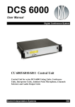
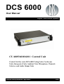
CU 6005/6010/6011 Central Unit
Central Unit for series DCS 6000 Voting Units, Conference
Units, Interpreter Units, Ambient Noise Microphone, Channels
Selectors and Audio Output Units
Danish Interpretation Systems
DIS
Danish Interpretation Systems
Copyright © 2007 DIS
User Manual
CU6005 6010 6011 REV V.DOC
16-07-2007
No part of this publication may be reproduced or utilised in any form or by any means without permission in writing from the
publisher.
Danish Interpretation Systems
User Manual
List of Contents
List of Contents..................................................... 3
System settings ..............................................23
Important .............................................................. 5
Normal Operation ..........................................23
Compliancy........................................................ 5
System Setup........................................................24
Important safety instructions........................... 5
General guidelines ...........................................24
Labels ................................................................. 5
Built into 19” Racks.........................................24
Installation precautions .................................... 5
Maximum number of units to be connected..25
CM/DM 60x0P Chairman/Delegate Units – CU
6010/6011 ......................................................25
Cleaning & Repacking...................................... 6
Warranty ........................................................... 6
Description of the DCS 6000 system ................... 7
Features.............................................................. 7
System components........................................... 8
Central equipment etc...................................... 8
Interpreter equipment ...................................... 8
Voting equipment............................................ 8
Conference equipment and channel selectors . 8
Operating instructions ......................................... 9
CU 6010 Central Unit ....................................... 9
General description ......................................... 9
Features ........................................................... 9
Feature License ............................................... 9
User Controls, indications & connectors....... 10
System settings.............................................. 12
Normal Operation.......................................... 20
CU 6011 Central Unit ..................................... 21
General description ....................................... 21
CM/DM 60x0P Chairman/Delegate Units – CU
6005 ...............................................................25
CM/DM 60x0P Chairman/Delegate Units & JB
6002 Junction Box – CU 6010/6011..............25
CM/DM 6060F/6510F Chairman/Delegate
Units – CU 6010/6011 ...................................26
CM/DM 6560F Chairman/Delegate Units – CU
6010/6011 ......................................................26
DC 6990P Conference Units – CU 6010/6011
.......................................................................27
DC 6990P Conference Units – CU 6005 .......27
MU 6040C/D and MU 6042D without
connected loudspeaker – CU 6010/6011 .......28
IS 6132P Interpreter Units – CU 6010/6011..28
IS 6132P w/JB 6004 and LS 6032 – CU
6010/6011 ......................................................29
CS 6032F Channel Selector w/back light on –
CU 6010/6011................................................29
Typical schematics...........................................30
Small conference microphone system with CU
6005 ...............................................................30
CU 6005 Central Unit ..................................... 22
General description ....................................... 22
Small conference microphone system with CU
6010 ...............................................................30
Features ......................................................... 22
Large size conference microphone system ....31
Feature License ............................................. 22
Microphone conference system with
interpretation CU 6010 ..................................31
User Controls, indications & connectors....... 23
Copyright © 2007 DIS
CU6005 6010 6011 REV V.DOC
16-07-2007
No part of this publication may be reproduced or utilised in any form or by any means without permission in writing from the
publisher.
Danish Interpretation Systems
User Manual
Microphone conference system with 3+1 ch.
interpretation & IR, CU 6005........................ 32
Microphone conference system with 15+1 ch.
interpretation & IR, CU 6010........................ 32
Various configurations with RP 6004 Repeater
and PS 6000 Power Supply ........................... 33
Appendix ..............................................................36
Technical appendix..........................................36
Cabling...........................................................36
Accessories (not supplied) .............................37
Technical specifications.................................38
Small system with SW 6000 Conference
Management Software................................... 34
Large system with SW 6000 Conference
Management Software................................... 35
Copyright © 2007 DIS
CU6005 6010 6011 REV V.DOC
16-07-2007
No part of this publication may be reproduced or utilised in any form or by any means without permission in writing from the
publisher.
Danish Interpretation Systems
User Manual
Important
The equipment must be connected to earth
Compliancy
The equipment has been tested and found to comply
with the limits of the following standards for digital
devices:
•
•
•
•
•
EN55103-1 (Emission)
EN55103-2 (Immunity)
EN60065 safety
UL6500 safety
FCC rules part 15, class A (Emission)
Warning – To reduce the risk of fire or electric
shock, do not expose this apparatus to rain or
moisture.
Apparatus shall not be exposed to dripping or
splashing and no objects filled with liquids, such as
vases, shall be placed on the apparatus.
Labels
The device complies with part 15 of the FCC rules.
Operation is subject to the following conditions: (1)
The device may not cause harmful interference, and
(2) the device must accept any interference
received, including interference that may cause
undesired operation.
These limits are designed to provide reasonable
protection against harmful interference when the
equipment is operated in residential, commercial or
light industrial environments. The equipment
generates, uses, and can radiate radio frequency
energy and if not installed and used in accordance
with the user manual it may cause harmful
interference to radio communications.
You are cautioned that any changes or
modifications not expressly approved in this manual
could void your authority to operate this equipment.
Lightning Flash Symbol, with
"The Lightning Flash with
arrowhead symbol within an
equilateral triangle, is intended
to alert the user to the presence
of uninsulated "dangerous
voltage" within the product
enclosure that may be of sufficient magnitude to
constitute a risk of shock to persons"
Exclamation Point Symbol,
with "The exclamation point
within an equilateral triangle is
intended to alert the user to the
presence
of
important
operating and maintenance
(servicing) instructions in the
literature accompanying the product"
Important safety instructions
Check that the voltage of your local power supply is
within the operating voltage of the unit (100-240V
AC). If a voltage conversion is required, consult
your DIS dealer or qualified personnel.
Should any liquid or solid object fall into the
cabinet, unplug the unit and have it checked by
qualified personnel before operating it further.
Set the Power switch to OFF if it is not used for
several days.
Installation precautions
Allow adequate air circulation to prevent internal
heat built-up. Do not place the unit on a surface
(rugs, blankets, etc.) that may block the ventilation
holes.
Do not install the unit in a location near heat
sources such as radiators or air ducts, or in a place
exposed to direct sunlight, excessive dust or
humidity, mechanical vibration or shock.
Manual 01 18 04438
5
Danish Interpretation Systems
User Manual
To avoid moisture condensations do not install the
unit where the temperature may rise rapidly.
Warranty
When installing the unit inside a 19” rack, observe
that the rack is properly ventilated. The maximum
allowed temperature inside the rack is 40 °C.
The unit is minimum covered by 12 months
warranty against defects in materials or workmanship.
Cleaning & Repacking
To keep the cabinet in its original condition,
periodically clean it with a soft cloth. Stubborn
stains may be removed with a cloth lightly
dampened with a mild detergent solution. Never use
organic solvents such as thinners or abrasive
cleaners since these will damage the cabinet.
Save the original shipping cardboard box and
packing material; they will become handy if you
ever have to ship the unit. For maximum protection,
re-pack the unit as originally packed from the
factory.
6
Manual 01 18 04438
Danish Interpretation Systems
User Manual
Description of the DCS 6000 system
•
Features
The DCS 6000 system has the following main
features:
Added functionality and comprehensive
features provided by SW 6000 software
package running on PC
RS232/RS422
connection
on
CU
6005/6010/6011 for external operation of the
system of a PC or control system such as AMX
or Crestron
•
Fully digital
•
Excellent sound quality
•
“State of the Art” fully digital integrated
interpretation, discussion and voting system
offering interpretation, language distribution,
conference microphone and voting facilities
with attendance check with Chip Card ™.
The SW 6000 is an optional software package,
which expands the functionality of the DCS 6000
system. The software runs on standard computer
technology (Standard PC with Windows 2000 or
XP).
•
Unique digital DATA and AUDIO bus.
Main features of the SW 6000 are:
•
39 incoming channels (8 floor channels + 31
interpreted channels) and one Line input.
•
34 distributed channels (3 x floor + 31
interpreted channels)
•
The Delegate and Interpreter units are powered
and controlled by the CU 6005 Central Unit,
which drives up to app. 50 units on 2 chains or
by the CU 6010/6011 Central Unit, which
drives up to app. 200 units on 4 chains.
•
Microphone management
•
Mimic panel operation
•
Interpretation management
•
Voting management
•
Message handling
•
Agenda handling
•
Data stored on SQL data base
•
EX 6010 Extension Units or PS 6000 Power
Supplies available if more units are required
•
Web service interface available for easy links
to external applications
•
A total of 4000 units (delegate and/or
interpreter units) can be connected to the
system.
•
Multi language user interfaces
•
Supports different User types with different
priorities, user interfaces and control
possibilities
•
Variety of printing facilities such as speaker’s
log, voting results, delegates list etc.
•
Using screened CAT5 or CAT5e cabling (FTP
or STP) ensuring a very cost effective
installation and easy set-up of portable systems
•
Firmware in Delegate units, Interpreter Units,
Central Units etc. upgradeable through serial
PC-connection (RS232 or RS422)
•
Can be operated with or without a PC.
Manual 01 18 04438
7
Danish Interpretation Systems
User Manual
System components
Conference equipment and channel
selectors
The CU 6005/6010/6011 Central Unit supports all
available units in the DCS 6000 series:
CS 6032F V/H
DC 6990P
Central equipment etc.
EX 6010
PS 6000
AO 6004
AO 6008
RP 6004
JB 6002
JB 6004
Extension Unit
Power Supply
Audio Output box
Audio Output box
Repeater for four chains
Junction Box with 2 outputs
Junction Box with 4 outputs
DM 6010P
DM 6060P
CM/DM 6070P
CM/DM 6090P
CM/DM 6060F
Interpreter equipment
IS 6132P
LS 6132P
Interpreter Set
Interpreter Loudspeaker
Voting equipment
DV 6501F
CM/DM 6510F
CM/DM 6560F
Voting Unit
MU 6040C/D
MU 6042D
AM 6040
Channel Selector (flush mounted)
Conference Unit (portable) with
touch screen
Conference Unit (portable)
Conference Unit (portable) with
one built-in channel selector
Conference Unit (portable) with
two built-in channel selectors
Conference Unit (portable) with
two built-in channel selectors and
XLR microphone connector
Conference Unit (flush mounted)
with one built-in channel
selectors
Conference Unit (flush mounted)
with Chip-card and 3 voting
buttons
Conference Unit (flush mounted)
with one built-in channel
selector, Chip-card and 3 voting
buttons
Microphone Unit for use with
customised front plate with
Loudspeaker, Microphone and
Buttons. Available in Delegate
(D) and Chairman (C) version
Dual Microphone Unit for use
with FD/FC front plate with
Loudspeaker, Microphone and
two delegate Buttons
Ambient Noise Microphone
Important: For the use of above mentioned equipment connected to a CU 6005/6010/6011 Central Unit,
please refer to the User Manuals for the equipment.
8
Manual 01 18 04438
Danish Interpretation Systems
User Manual
Operating instructions
•
Delayed switching on of power to the four
chains, to minimise the total ‘in-rush’ current
on the Mains supply.
General description
•
Designed in a standard 2HE 19” cabinet.
The CU 6010 Central Unit for the DCS 6000 is the
heart of the system. One CU 6010 is needed in each
DCS 6000 system. The CU 6010 consist of four
main parts:
•
Functionality on the CU 6010 depends on the
Feature License uploaded into the unit.
CU 6010 Central Unit
•
Main processor board with Power PC and DSP
•
DCS-LAN Network Control Card with 4
individual DCS-LAN outputs
•
4 individual Power supplies
•
LCD display and buttons for system settings
The design with built in power supply makes the
unit suitable for running a small system alone or to
be the Central Controller for a large system.
Features
The main features of the CU 6010 Central Unit are:
•
Controls up to 4000 units (Conference units,
Interpreter units or other controllable units).
This number does not include Channel
Selectors, Repeaters etc. In practical use there
are no limits for the number of Channel
Selectors in a system.
•
Designed for 31 interpreted channels and 8
open microphones
•
Operated either stand alone or from an IBM
compatible PC with SW 6000 software running
under Windows 2000 or XP.
•
Built in Power Supplies for app 200 units
(Delegate) or app. 600 Channel Selectors
•
4 outputs for connection to Delegate Units,
Interpreter Units etc.
Feature License
The CU 6010 Central Unit has as standard basic
functionality.
•
•
•
•
•
Conference Units:
max. 50
This count includes DM, CM, DV units.
Dual Delegate units count for 2 units.
Secure audio transmission:
No
Vox, voice activating:
No
Voting:
No
Interpretation Channels:
1-4
By obtaining feature licenses, the functionality can
be expanded to include further functionality like:
•
•
•
•
•
•
Conference Units, max.100, max. 500,
max. 1000 or max. 3800
This count includes DM, CM, DV units.
Dual Delegate units count for 2 units
Secure audio transmission
Voting option
VOX, Voice Activation
Interpreter Channels, 1-8 channels, 1-16
channels or 1-31 channels
3 part voting control using RS232 port on
CU 6010
The file with the Feature License key is delivered
from your authorised DIS Distributor or Dealer and
can be uploaded in the CU using a standard PC or
Laptop. For details about uploading the Feature
license, please consult the User Manual “DCS6000
Feature License Key”.
This manual describes all features available
Manual 01 18 04438
9
Danish Interpretation Systems
User Manual
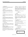
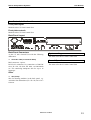
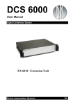
User Controls, indications & connectors
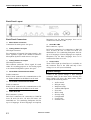
Front plate layout
The front plate layout of the CU 6010 Central Unit consists of a large illuminated LCD display and 8 buttons for
setting up/controlling the system:
Details of display
-Audio Control
-Delegate setup
-Interpreter setup
-Units info
MENU
Front plate controls
The CU 6010 Central unit features the following
controls and display:
Power switch
Switches power on to the whole system. When
power is switched ON at the CU 6010 any
connected EX 6010 Extension Units will
automatically be powered up. An indication in the
switch is lighting, when power is switched ON
Fault LED
This indication lights up, if the internal power
supply is malfunctioning i.e. because of overheating
or overload of a chain.
10
ENTER
The Fault LED will always light up some seconds
after the unit is switched on caused by the delayed
switching on of the four supplies.
As a warning the light is flashing at an internal
temperature above 45°C. At a temperature above
55°C or if one of the DCS-LAN outputs is
supplying no voltage, the LED is lighting
constantly.
Please note that the maximum ambient temperature
for the CU 6010 is 40 deg. Celsius.
LCD Display
This display is used for information purposes and
set-up purposes.
Manual 01 18 04438
Danish Interpretation Systems
User Manual
Buttons
The buttons below and to the left of the display are
used when stepping through the different menus
and for setting up the system:
•
Enter button
The Enter button is used, when a selection is made
in the Main Menu. Pressing the Enter button
concludes the selection made, and at the same time
it indicates a confirmation of the possible changes
made within the selection. The Menu system returns
to the previous menu. Notice, that some changes are
applied immediately, and confirmation is thus not
required.
•
Menu button
Up (▲) and Down (▼) buttons
The Up and Down buttons are used to scroll
through menu items, or to increase/decrease values
within a selection.
Symbols
The following symbols are used on the LCD
display:
‘>’
The ‘>’ symbol preceding a line of text identifies a
selected parameter. The parameter can be changed
by pressing the up and down buttons. The ‘>’
symbol is shown as long as the value of the
parameter currently used is the same as the value
shown in the display.
‘*’
The star symbol ‘*’ preceding a line of text
identifies a selected parameter, where the value has
been changed, but not yet confirmed. The changed
value can be confirmed by pressing the Enter
button, or it can be dismissed by pressing the Menu
button.
The Menu button is also used, when a selection is
made in the Main Menu. The Menu button
concludes the selection, but in contrast to the Enter
button, the Menu button does not confirm a possible
change made within the selection. Instead, the
Menu system returns to the previous menu without
confirming changes, if confirmation is required.
•
The dash symbol (‘-‘) preceding a line of text
identifies a submenu or a changeable parameter.
The submenu or parameter can be selected by
pressing the corresponding select button.
Four select buttons
Four buttons placed on the left-hand side of the
display. Each button is associated with a line
pointing towards a text line in the display. This
indicates, that pushing the button ‘selects’ the
functionality.
•
‘-‘
‘▲▼’
The up and down symbols shown in the right side
of the display (up is shown in the first line and
down is shown in the last line) indicates that the
current menu consists of more than 4 menu items. It
is therefore necessary to use the up and down
buttons to scroll through menu items.
Indications
Cursor
The cursor is used on the LCD display to indicate,
when a value is being changed. For a parameter that
is subject to a change, the cursor is placed at the
value of the parameter, indicating that it is about to
be changed.
Manual 01 18 04438
11
Danish Interpretation Systems
User Manual
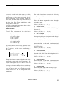
Back Panel Layout
Interpreter sets for those languages have to be
connected to Chain B1 or B2.
Back Panel Connectors
Mains Power connector
Connection for mains power. See specs.
Chain B1 & B2
RJ45 connector, 2 pieces
Analog Audio Line input
XLR Input connector.
For connection of external Line input signal i.e. the
Floor (Speaker) signal from another Conference
Microphone System or audio mixers. See specs.
Analog Audio Line output.
XLR Output connector.
This connector carries the “Floor” signal. It is used
either for recording purposes or for feeding signal
to an external loudspeaker system. See specs.
RS232 Serial connection for communication to PC
etc. Either the RS232 or the RS422 can be used.
Those LED’s light up when Power is available on
the connector next to the LED and only if the
voltage is over 24V (not overloaded).
Control of the system settings is done through
selections made in the main menu. Pressing the
Menu button will show the Main menu, which
comprises the following entries:
Serial Data Communication RS422
D-Sub 9 connector
RS422 Serial connection for communication to PC
etc. Either the RS232 or the RS422 can be used.
Chain A1 & A2
RJ45 connector, 2 pieces
DCS-LAN connectors for connection to DM/CM
6xxx, IS 6032, IS 6132, CS 6032, EX 6010, AO
6004/6008 etc. For connecting Interpreter Sets for
up to 16 languages. If more languages are required,
12
Power LED’s
System settings
Serial Data Communication RS232
D-Sub9 connector
DCS-LAN connectors for connection to DM/CM
6xxx, IS 6032, IS 6132, CS 6032, EX 6010, AO
6004/6008 etc. For connecting Interpreter Sets for
up to 16 languages. If more languages are required,
Interpreter sets for those languages have to be
connected to Chain A1 or A2.
Manual 01 18 04438
•
•
•
•
•
•
•
•
•
•
Audio control
Delegate setup
Interpreter setup
Ambient Microphone
Units info
RS232 setup
Security setup
Configuration
License info
Firmware info
Danish Interpretation Systems
User Manual
A selection is made in the Main menu by scrolling
through the menu items with the Up/Down buttons,
and pressing the Select button associated with the
desired menu item. When scrolling through the
menu items, the Main menu wraps around the list of
menu items, i.e. passing the last menu item makes
the first menu item appear, and likewise when
passing the first menu item.
Pressing the Menu and Enter buttons does not have
any effect in the Main Menu.
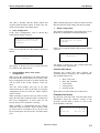
Audio control
By pressing the select button for the “Audio
Control” menu adjustment of the audio levels
becomes possible:
•
•
•
•
•
•
•
The Audio Control menu comprises the following
complete list of adjustment items:
Values: {Off, -40, -39, …, -1, 0}
LineOut volume
The audio volume of the ‘LINE OUTPUT’ signal
from the CU.
Values: {Off, -40, -39, …, 19, 20}
Loudspk volume
LineOut volume
Mic->Loudspk
Mic->LineOut
LineIn->Loudspk
LineIn->LineOut
LineInlevel Adj
Loudspk volume
This is the Master Loudspeaker volume, the audio
level of the loudspeakers of the delegate
microphone units.
Mic->Loudspk
Attenuation/Gain of the audio signal transmitted
from speaking delegate microphones to the delegate
microphone unit loudspeakers.
Values: {Off, -40, -39, …, 19, 20}
By pressing the first select button, adjustment of the
loudspeaker volume is selected. This is indicated by
the ‘>’-indicator, and the cursor starts flashing at
the value:
Mic->LineOut
Attenuation/Gain of the audio signal transmitted
from speaking delegate microphones to the ‘LINE
OUTPUT’ signal.
Values: {Off, -40, -39, …, 19, 20}
LineIn->Loudspk
Attenuation/Gain of the audio signal transmitted
from the ‘LINE INPUT’ to the loudspeakers of the
delegate microphone units.
>Loudspk volume: -7dB ▲
-LineOut volume:
4dB
-Mic->Loudspk:
-10dB
-Mic->LineOut:
0dB ▼
Values: {Off, -40, -39, …, 19, 20}
The up/down buttons can now alter the value of the
loudspeaker volume. A change made to the
loudspeaker volume takes effect immediately. The
volume is changed in steps of 1 dB. The value of 0
indicates ‘standard’ setting.
Pressing the Menu or the Enter button ends change
of loudspeaker volume. Change of other audio
levels is done the same way as for the loudspeaker
volume in steps of 1 dB. All changes take effect
immediately.
LineIn->LineOut
Attenuation/Gain of the audio signal transmitted
from the ‘LINE INPUT’ to the ‘LINE OUTPUT’.
Values: {Off, -40, -39, …, 19, 20}
LineInlevel Adj
Attenuation/Gain of the XLR audio input signal
from the ‘LINE INPUT’.
Values: {Off, -40, -39, …, -1, 0}
Manual 01 18 04438
13
Danish Interpretation Systems
User Manual
Values: {Auto, Manual, FIFO, VOX}:
Delegate setup
The “Delegate setup”
following entries:
•
•
•
•
•
menu
comprises
the
•
Max Speakers
Max. Requests
Operation Mode
Voice Detection
Auto Off Setup
This is indicated by a red light in the
‘Speak’ lamp in the microphone unit.
Pressing the microphone ON/OFF button
again will turn the microphone off
Max Speakers
A Chairman Unit is always in Auto or VOX
mode.
This menu point has two settings:
•
•
•
Max. Total Speakers
Max. Delegate Speakers
Values: {1, 2, 3, 4, 5, 6, 7, 8}
The number of ‘Total Speakers’ defines the
maximum number of conference units, which can
speak at the same time. This includes both delegate
and chairman units.
Please observe that a Chairman Unit can always be
switched ON as long as the number set in ‘Max.
Total Speakers’ are not exceeded.
Although it is possible to switch to this
mode in a stand-alone-system, this mode is
only used with an attached PC running SW
6000 software or using with a control
system.
Max Requests
“Max Requests” defines how many delegate units
that can be inserted into the list of delegates
requesting to speak at the same time.
•
Values : {0, 1, …, 255}
Operation Mode
This menu point has two settings:
•
•
•
Operation mode
Interrupt
Operation mode
The “Operation Mode” determines the behaviour of
the microphone system.
14
Manual mode features a request list, where
‘Delegates’ are inserted in a queue upon
pressing the microphone ON/OFF button.
This is confirmed by a steady green light in
the ‘Request’ lamp in the delegate unit. It is
possible to cancel the request by pressing
the button again.
The microphone can only be switched on
from a PC running SW 6000 software or
from a control system like AMX or
Crestron. This will be indicated by red light
in the ‘Speak’ lamp in the microphone unit.
At this point the delegate can switch off the
microphone by pressing the ON/OFF
microphone button.
The number of ‘Delegate Speakers’ defines the
maximum number of Delegate conference units,
which are allowed to speak at the same time is
defined as “Max Speakers”.
Auto (or Automatic) mode allows for the
microphone units to be switched on
immediately upon pressing the microphone
ON/OFF button.
Manual 01 18 04438
FIFO is an automated mode. The
microphone unit functions in the same way
as in automatic mode as long as the number
of turned on delegate units is less or equal
to the selected maximum speakers.
When the max. number is reached, the next
delegate pressing the ON/OFF button will
be put in the top of the request queue. This
is indicated by the green ‘Request’ lamp
flashing slowly.
Danish Interpretation Systems
User Manual
More delegates will be put in the request
queue when they press their ON/OFF
buttons, until the maximum of requests is
reached. Their green ‘Request’ lamps will
light up steadily.
When one of the turned ON microphone
units is switched off, the first delegate unit
in the queue is automatically switched ON,
and the next delegate unit in the queue will
flash with the green ‘Request’ lamp.
This mode will normally be used with only
1 as maximum speakers.
•
VOX, voice activation mode allows for the
microphone units to be switched on
automatically if speaking in the microphone
or by pressing the microphone ON/OFF
button.
This is indicated by a red light in the
‘Speak’ lamp in the microphone unit.
Pressing the microphone ON/OFF button
again will turn the microphone off.
The microphone turns of automatically
after finished talking after the time defined
in the “Release Time” setting (se later
paragraph), which normally is 4 seconds.
The microphone can also be turned off by
pressing the ON/OFF button.
A Chairman Unit is always in Auto or VOX
mode
•
but 3 flashes in the green LED will indicate, that the
maximum number has been reached.
It is similar for Chairman units if the number of
open units (Chairman and Delegate) has reached the
number specified in the setting “Max. Total
Speakers”.
Lower
If however “Lower” is selected a chairman will
interrupt (switch Off) the first switched On delegate
unit if the number of open units (Chairman and
Delegate) has reached the number specified in the
setting “Max. Total Speakers”.
Lower+Same
If “Lower+Same” is selected a delegate unit will
interrupt (switch Off) the first switched On delegate
unit if the number of delegate units has reached the
number specified in the setting “Max. Delegate
Speakers”.
Similar a chairman will interrupt (switch Off) the
first switched ON delegate unit if the number of
open units (Chairman and Delegate) has reached the
number specified in the setting “Max. Total
Speakers”, and if no delegate unit is switched ON
the first switched ON Chairman unit will be
switched OFF.
Voice Detection
This menu point has two settings:
•
•
Interrupt
The “Interrupt” setting determines the behaviour of
the microphone units.
Values: {None, Lower, Lower+Same}
Treshold
Release time
Those settings determines the behaviour of the
system when working in VOX mode
•
Treshold
Values: {-5,-4,-3, -2, -1, 0,1,2,3,4,5}
None
When “None” is selected and the number of open
Delegate units has reached the number specified in
the setting “Max. Delegate Speakers” no more
delegate microphone can be opened. Pressing the
microphone buttons will not turn on the microphone
The default value is ‘0’. Setting to a lower value
makes the microphone more sensitive.
•
Release time
Values: {from 1 to 10 seconds in 0.5 sec step}
Manual 01 18 04438
15
Danish Interpretation Systems
User Manual
This setting is used to set the time from the delegate
stops talking until the microphone turns off. The
default value is 4 sec.
Channel 0 will always give the original audio
(floor).
Auto Off Setup
This menu point has two settings:
•
•
Auto Off
Auto Off time
Those settings determine the behaviour of the Auto
Off facility for the conference units.
•
When set to 0 value no interpretation channels are
present in the system. Only ‘Floor’ sound will be
present
-Channel
-Channel
-Channel
-Channel
Auto Off
Values: {On,Off}
When set to On a conference unit will automatic
turn of the microphone when the delegate stops
talking. The time is determined by the ‘Auto Off
time’ setting.
•
Auto Off time
Values: {from 5 to 60 seconds in 5 second steps}
This setting is used to set the time from the delegate
stops talking until the microphone turns off. The
default value is 5 sec.
Language setup
The “Language setup” menu will show the number
of channels according to the ‘Interpreter Channels’
settings. :
1:
Arabic ▲
2: Bulgarian
3:
Danish
4: Vietnamese ▼
A channel entry is selected with the select keys 1-4
and the language for that channel can be chosen
with the up/down buttons. If the value is changed is
indicated with “>” to the left of the entry.
The new language selection is accepted with Enter
button and cancelled with Menu button.
Booth Setup
When the system is set to VOX mode Auto Off
settings are disabled.
The “Booth Setup” menu will show a list op Booth
(1 to 128).
Interpretation setup
The Interpretation Channels can now be assigned to
the Booth. More Booths can be assigned the same
channel.
The “Interpretation setup” comprises the following
entries:
•
•
•
•
•
•
As default Booth 1 is assigned Channel 1, Booth 2
assigned Channel 2 etc.
Interpreter Channels
Language setup
Booth Setup
Auto Floor
Interpreter Lock
Channel Display
When set to ON a language channel with no
interpretation will have the Floor sound.
Values: {On, Off}
Interpreter Channels
This setting is used to set the number of Interpreter
Channels in use.
Values: {0 to 31}
16
Auto Floor
Interpreter Lock
The Interlock settings are used to setup the interlock
between the Interpretation channels.
The settings are:
Manual 01 18 04438
Danish Interpretation Systems
•
User Manual
Complete Lock
With this setting an interpreter cannot switch on his
microphone to any occupied interpreter channel.
This is the default setting.
•
No Lock
With this setting an interpreter turning on his
microphone to any occupied interpreter channel,
will turn of the interpreter occupying the channel.
•
Transmission of ambient noise rather than
transmitting no sound at all is a desirable feature
from listeners attending the meeting via
headphones. The ambient noise indicates to the
listeners, that there is no speaking activity going on,
and this information is very nice to have, when
interpreters are doing interpretation, and the speaker
stops speaking.
The setup menu has the following options:
•
•
Interlock
Those settings are used to give various interlocks.
A interrupt A
An interpreter turning on his microphone on an Achannel will interrupt another interpreter using his
A channel
A interrupt B
An interpreter turning on his microphone on an Achannel will interrupt another interpreter using his
B channel, but will not interrupt an interpreter using
his A channel.
Amb.Mic
Amb.Mic Level
Amb.Mic
When ‘enabled is selected, the Ambient Noise
Microphone is active.
When the LineIn>Loudspk under Audio control is
set to a value between -40dB and +20dB the
microphone
will
be
disabled.
If
the
LineIn>Loudspk subsequently is set to Off, the
microphone will stay disabled until enabled in
Amb.Mic.
Values: {Enabled, Disabled}
A interrupt A+B
An interpreter turning on his microphone on an Achannel will interrupt another interpreter using his
A or B channel.
Amb.Mic Level
Adjust the level of the microphone to a level, which
is suitable for the listener (Interpreter).
Values: {Off, -40, -39, …,18, 19, 20}
Channel Display
This setting is used to switch the showing in the
channel selectors displays in conference units
between Language Abbreviation and Channel
Number.
Ambient microphone
The user returns to the main menu by pressing
either the Menu button or the Enter button.
Units info
Selecting “Units info” from the Main menu, the
Units info menu is entered:
•
•
By choosing ‘Ambient Microphone’ from the main
menu and parameters for an AM 6040 Ambient
Noise microphone can be set up
The purpose of an ambient noise microphone is to
provide sound from a meeting room/conference
hall, when there is no delegate/chairman using their
microphones.
Display Chain info
Display Unit types
Display Chain Info
Selecting the first select button makes the system
enter the Chain Information display. This display
looks like this:
Chain A (f):
2
Chain B (f):
2
Total (f/e):
4/5
f:found, e:expected
Manual 01 18 04438
17
Danish Interpretation Systems
User Manual
The Chain info menu displays information to the
user about units connected to the CU. The
information is divided into Chain A, Chain B and
total. Found units are connected units, where the
communication is maintained, and expected units
comprises all units, which are defined in the
‘Configuration’.
Display Unit types
Selecting the Display Unit types in the Units info
menu displays the number of present units. The
available units are:
•
•
•
•
•
•
•
•
By protecting the communication (“Protected”), the
risk of faulty communication via RS232/RS422 is
minimized.
The risk of faults via RS232/RS422 is higher
running the “Default” mode; however, the
communication is possible from standard interfaces.
Menu button or Enter button leaves this screen.
The “Input mode” defines whether the ASCII
communication via RS232/RS422 is protected by
CRC check or not.
The RS232 terminal interface emulator, Tera Term,
does not feature the possibility of guarding the
ASCII communication by CRC check.
Values: {Default, Protected}
Delegate units
Dual Mic. units
Chairman units
Voting units
Interpreter units
Audio Output units
Amb. Mic units
External Control
Security setup
The setup determines if ”Audio Scrambling” is
activates or not.
Values: {Off, On}
For external control it is indicated by ‘ON’ or
‘OFF’ whether an external PC is connected and
communicating (alive) via the RS232/RS422
connection to the CU.
Menu button or Enter button leaves this screen.
Default value is ‘off’. When switching to ‘on’, the
CU has to be restarted. All units will automatically
change to the scrambled mode.
The scrambling mode is used in high security
places, when ears dropping cannot be accepted.
Configuration
The “Configuration” menu comprises three menu
items:
RS232 setup
•
•
•
The RS232 setup menu consists of two setup issues:
•
•
RS232 baudrate
RS232 mode
RS232 baudrate
The “RS232 baudrate” determines the bit rate of the
communication between the CU and an external
unit connected via the RS232 or RS422 connection.
18
Load configuration
The “Load configuration” item brings the user to
the Load configuration confirmation display:
Values: {2400, 4800, 9600, 19200, 38400, 57600,
115200}
Load configuration
Save configuration
Delete configuration
RS232 mode
Manual 01 18 04438
This will overwrite
Current setup.
Continue?
Danish Interpretation Systems
User Manual
The load is aborted with the Menu button and
accepted with the Enter button. In both cases, the
menu system returns to the Main menu.
When switching the power to the CU 6010 OFF and
then ON, the last saved setting will also be loaded.
Save configuration
If the “Save configuration” item is chosen this
confirmation display is shown:
Delete configuration
The “Delete configuration” item brings the user to
the Delete configuration confirmation display:
This will delete the
configuration in flash.
Continue?
This will overwrite the
configuration in flash.
Continue?
If the user accepts the save the progress display is
shown:
If the user accepts the deletion the progress display
is shown:
Deleting...
Saving...
The display is shown for a few seconds before the
CU returns to the “Main menu”.
Understanding “Save” and “Load”
configuration
When saving the configuration, the setting that has
been done in the various menus in CU 6010, at the
IS 6132 Interpreter Sets and at AO 6008 Audio Unit
will be saved in the ‘Flash’ memory in the CU
6010.
Also the serial number and type of all units
connected to the CU 6010 at the time of saving the
configuration will be saved in the ‘Flash’ memory
in the CU 6010.
When switching on power to the CU 6010 at a later
stage, then the units connected will be compared to
the saved configuration. If some units are not
present, they will be reported as ‘missing’
The display is shown for a few seconds before the
CU returns to the “Main menu”.
License info menu
Selecting the License info menu displays the
available features enabled by the current license.
The available features are:
•
•
•
•
•
Max. Conf. units
Max. Intp. Channels
VOX option
Voting option
Security option
Menu button or Enter button leaves the screen.
Firmware info menu
By choosing ‘Firmware info’ from the main menu
information about the software version of the
PowerPC and the DSP is shown as well as the
Serial Number of the unit:
When ‘loading’ a configuration the last settings,
which has been saved in the ‘Flash’ memory in the
CU 6010 will be re-loaded to the CU 6010, to the
IS 6132 Interpreter Sets and to the AO 6008 Audio
Unit.
Manual 01 18 04438
PPC:
DSP:
Serial No:
5.3.86
1.0.48
111.111.111
19
Danish Interpretation Systems
User Manual
The user returns to the main menu by pressing
either the Menu button or the Enter button.
This screen is the standard screen showed at normal
use. This screen is automatically shown if no
buttons is pressed in 2 minutes. The function of this
screen is explained in the section Audio Control
menu.
Normal Operation
Powering up
Use with SW 6000
Switch on power at the CU 6010. After powering
up, the display on the CU 6010 is showing the
Start-up screen:
Please refer to the SW 6000 manuals.
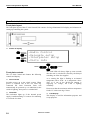
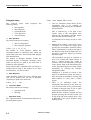
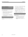
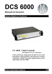
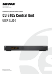
Schematics volume/gain settings
The volume controls, which can be set on the CU
6010 user interface as described in the previous
section are shown in the following schematic.
Initializing
Please Wait
Setting of Loudspeaker volume
1. Set the Mic>Loudspk to 0dB
2. Turn up the Loudspk Volume to the level
needed in the loudspeakers.
Digital Conference
System 6000
DIS
Setting Line input level
1. Apply the signal to the Input connector
2. Turn up the input level on “LineInlevel
Adj” until you can see the overflow
indicator.
Registration Mode
Unit registration
Microphones disabled
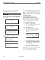
After initialising
displayed:
the
following
-Audio control
-Delegate setup
-Interpreter setup
-Ambient Microphone
-Loudspk volume:
-LineOut volume:
-Mic->Loudspk:
-Mic->LineOut:
screens
-LineIn->Loudspk: -17dB ▲
10dB
-LineIn->LineOut:
>LineInLevel Adj:* -6dB
-Loudspk volume:
3dB ▼
are
”*” Overflow indicator on line input
▲
▼
0dB ▲
0dB
-9dB
2dB ▼
3. Turn then the InputIn level down –8 dB to
–12dB from the clipping level. Depending
of the source connected, there might be
different “overhead” needed. But normally
8-12 db is enough.
4. Turn up the Linein >Loudspk Volume to
the level needed in the loudspeakers
The principle is that the level of signal from the
Line Input is combined of two settings:
“LinelnLevel Adj” and “LineIn->Loudspk”.
20
Manual 01 18 04438
Danish Interpretation Systems
User Manual
The LinelnLevel Adj has to be set as high as
possible for maintaining the best S/N ration, but not
too high to avoid clipping, whereas the LineIn-
>LoudSpk is used for setting the audio level needed
in the loudspeakers.
CU 6010 Orignal Audio Volume Control
Units
CU 60XX
DM1
LineOut volume
Mic > LineOut
5
1
a
D/A
LineIn > LineOut
LINE OUTPUT
3
DM2
a
2
Mic > Loudspk
LineInLevel Adj
Loudspk volume
DM
b
e
4
6
A/D
D/A
LineIn > Loudspk
AO/IS
LINE INPUT
d
D/A
CS/IS/DM
c
D/A
CU 6011 Central Unit
General description
The functionality of CU 6011 is identical to the CU
6010 Central Unit.
Manual 01 18 04438
21
Danish Interpretation Systems
User Manual
•
Controls up to max. 500 Conference/Voting
units. Controls of Interpreter Sets or other
controllable units are as for CU 6010.
General description
•
The functionality of CU 6005 is basically identical
to the CU 6010 Central Unit; however the main
parts are slightly different:
Designed for up to 16 interpreted channels
(instead of 31) and 8 open microphones
•
Built in Power Supply for app 50 Conference
Units (instead of 200) or app. 150 Channel
Selectors
•
2 outputs for connection to Delegate Units,
Interpreter Units etc. (instead of 4)
CU 6005 Central Unit
•
Main processor board with Power PC and DSP
•
DCS-LAN Network Control Card with 2
individual DCS-LAN outputs (instead of 4)
•
One Power supply (instead of 4)
Feature License
•
LCD display and buttons for system settings
•
1 slot in the back panel for inserting modules
e.g. AO 6004 (extra)
The optional Feature Licenses for the CU 6005 are
the same as for the CU 6010 Central Unit with the
following differences:
•
Features
The features of the CU 6005 are almost the same as
for the CU 6010 Central Unit with the following
differences:
22
•
Manual 01 18 04438
Conference Units, max.100 or max. 500.
This count includes DM, CM, DV units.
Dual Delegate units count for 2 units
Interpreter Channels, 1-8 channels or 1-16
channels
Danish Interpretation Systems
User Manual
User Controls, indications & connectors
Front plate layout
Identical to the CU 6010 Central Unit.
Front plate controls
Identical to the CU 6010 Central Unit.
Back Panel Layout
Back Panel Connectors
As the CU 6010 Central Unit with the following
differences:
Chain A1 & A2 (no chain B1 & B2)
System settings
The same as for the CU 6010 Central Unit.
Normal Operation
RJ45 connector, 2 pieces
DCS-LAN connectors for connection to DM/CM
6xxx, IS 6132, CS 6032, EX 6010, AO 6004/6008
etc. For connecting Interpreter Sets for up to 16
languages.
The same as for the CU 6010 Central Unit.
Other
Slot (extra)
Slot for inserting modules in the back panel, e.g.
AO 6004. Slot dimensions (W x H x D) 180 x 38 x
120 mm.
Manual 01 18 04438
23
Danish Interpretation Systems
User Manual
System Setup
General guidelines
Connect the CU 6005/6010/6011 to the various
DCS 6000 units using Cat5 or Cat5e FTP or STP
screened cables.
The operation of the DCS 6000 units is found in the
User Manual for the specific units.
between the units. Please consult the next
section ‘Maximum number of units to be
connected’.
•
The maximum number of languages
configured on chain A (A1 or A2) or B (B1
or B2) is 16. If more languages are
required, Interpreter sets for those
languages have to be divided between both
chains (A and B) – this is only applicable
for the CU 6010/6011. Normally the
languages are supposed to be divided
equally on chains A (A1 or A2) and B (B1
or B2).
•
If the last unit in one chain is a CS 6032
Channel Selector, this unit has to be
terminated with an external termination, as
the CS 6032 does not have an internal
automatic termination.
Please observe the following guidelines:
•
Maximum cable length in one chain is 200
m (before repeating). This includes
interconnection cables between the units.
The max. usable cable length depends on
the units connected and length of feeding
cables etc.
•
Maximum cable length in one chain when
using repeaters is 650 m.
•
Although the DCS-LAN Network Output
connectors (CU 6005: A1 plus A2, CU
6010/6011: A1, A2, B1 or B2) have a
125W supply, this 125W power is not all
available with long cables, as there will be
a power drop in the feeding cable from the
CU 6005/6010/6011 to the units connected.
If the feeding cables are short and the
cables between the units are short, more
units can be connected than if the feeding
cable is long and/or the cables are long
It is desirable that the square of the feeding cables
especially but also the interconnection cables are as
big as possible to minimize the voltage drop in the
cables. Cat 5/Cat5E cables are delivered in various
gauges:
The following table is showing the Diameter/square
for various AWG types:
Type
AWG22
Diameter
0.64 mm
Square
0.32 mm2
AWG23/1
0.57 mm
0.25 mm2
AWG24
0.53 mm
0.22 mm2
AWG26
0.42 mm
0.14 mm2
Built into 19” Racks
The unit has a built-in fan taking air in at the right
side of the unit and blowing the hot air out at the
right side. That allows units in 19” racks to be
24
stacked close with other units without extra room
for cooling air between them. Please check that the
other units will allow this.
Manual 01 18 04438
Danish Interpretation Systems
User Manual
Maximum number of units to be connected
The following table shows the maximum number of
units, which can be connected to each of the four
outputs (A1, A2, B1 or B2) on a CU 6010/6011
Central Unit or on each output on an EX 6010
Extension Unit or on the output of a PS 6000..
CM/DM 60x0P Chairman/Delegate Units – CU 6010/6011
Length of Feeding Cable
Type CAT5 AWG24
Length of inter connecting
Cable, Type CAT5 AWG24
Total cable length
Max. number of CM/DM
60x0P pr output
10 m
30 m
50 m
100 m
150 m
10 m
30 m
50 m
100 m
150 m
1m
1m
1m
1m
1m
2m
2m
2m
2m
2m
51 m
67 m
83 m
122 m
165 m
88 m
98 m
108 m
140 m
178 m
42
38
34
23
16
40
35
30
21
15
CM/DM 60x0P Chairman/Delegate Units – CU 6005
The following table shows the maximum number of
units, which can be connected to the two outputs
(A1 and A2) simultaneously on a CU 6005 in total
If only one chain is used the information in the
above table must be used.
Length of Feeding Cable
Type CAT5 AWG24
Length of inter connecting
Cable, Type CAT5 AWG24
Total cable length
Max. number of CM/DM
60x0P for both outputs
10 m
30 m
50 m
100 m
150 m
10 m
30 m
50 m
100 m
150 m
1m
1m
1m
1m
1m
2m
2m
2m
2m
2m
2x32 m
2x51 m
2x70 m
2x117 m
2x164 m
2x54 m
2x72 m
2x88 m
2x132 m
2x176 m
2x23
2x22
2x21
2x18
2x15
2x23
2x22
2x20
2x17
2x14
CM/DM 60x0P Chairman/Delegate Units & JB 6002 Junction Box – CU 6010/6011
This configuration shows two CM/DM 60x0P
Delegate/Chairman Units connected to one JB 6002
Junction Box with 3m cables between each JB
6002.
Maximum 5 m cable from JB 6002 to CM/DM
60x0 and maximum one CM/DM 60x0 on each
output of JB 6002.
Manual 01 18 04438
25
Danish Interpretation Systems
User Manual
Length of Feeding Cable,
Type CAT5 AWG24
Length of Cable between each
JB 6002, Type CAT5 AWG24
Total cable
length
Number of
JB 6002
Max. number of
DM 60x0
10 m
30 m
50 m
100 m
150 m
3m
3m
3m
3m
3m
61 m
75 m
89 m
127 m
168 m
18
16
14
10
7
36
32
28
20
14
CM/DM 6060F/6510F Chairman/Delegate Units – CU 6010/6011
The following table shows the maximum number of
units, which can be connected to each of the four
outputs (A1, A2, B1 or B2) on a CU 6010/6011
Central Unit or on each output on an EX 6010
Extension Unit or on the output of a PS 6000.
Length of Feeding Cable
Type CAT5 AWG24
Length of inter connecting
Cable, Type CAT5 AWG24
Total cable length
Max. number of
CM/DM 60x0 pr output
10 m
30 m
50 m
100 m
150 m
10 m
30 m
50 m
100 m
150 m
1m
1m
1m
1m
1m
2m
2m
2m
2m
2m
39 m
56 m
73 m
115 m
160 m
64 m
78 m
94 m
130 m
170 m
30
27
24
16
11
28
25
23
16
11
CM/DM 6560F Chairman/Delegate Units – CU 6010/6011
The following table shows the maximum number of
units, which can be connected to each of the four
outputs (A1, A2, B1 or B2) on a CU 6010/6011
26
Central Unit or on each output on an EX 6010
Extension Unit or on the output of a PS 6000.
Length of Feeding Cable
Type CAT5 AWG24
Length of inter-connecting
Cable, Type CAT5 AWG24
Total cable length
Max. number of CM/DM
60x0 pr output
10 m
30 m
50 m
100 m
150 m
10 m
30 m
50 m
100 m
150 m
1m
1m
1m
1m
1m
2m
2m
2m
2m
2m
35 m
53 m
70 m
113 m
159 m
58 m
72 m
88 m
126 m
166 m
27
24
21
14
10
25
22
20
14
9
Manual 01 18 04438
Danish Interpretation Systems
User Manual
DC 6990P Conference Units – CU 6010/6011
The following table shows the maximum number of
units, which can be connected to each of the four
outputs (A1, A2, B1 or B2) on a CU 6010/6011
Central Unit or on each output on an EX 6010
Extension Unit or on the output of a PS 6000.
Length of Feeding Cable
Type CAT5 AWG24
Length of inter connecting
Cable, Type CAT5 AWG24
Total cable length
Max. number of
DC 6990P pr output
10 m
30 m
50 m
100 m
150 m
10 m
30 m
50 m
100 m
150 m
1m
1m
1m
1m
1m
2m
2m
2m
2m
2m
35 m
53 m
70 m
112 m
158 m
56 m
72 m
90 m
124 m
166 m
26
24
21
13
9
25
22
19
13
9
DC 6990P Conference Units – CU 6005
The following table shows the maximum number of
units, which can be connected to the two outputs
(A1 and A2) simultaneously on a CU 6005 in total
If only one chain is used the information in the
above table must be used.
Length of Feeding Cable
Type CAT5 AWG24
Length of inter connecting
Cable, Type CAT5 AWG24
Total cable length
Max. number of
DC 6990 for both outputs
10 m
30 m
50 m
100 m
150 m
10 m
30 m
50 m
100 m
150 m
1m
1m
1m
1m
1m
2m
2m
2m
2m
2m
2x34 m
2x43 m
2x62 m
2x110 m
2x158 m
2x36 m
2x54 m
2x90 m
2x118 m
2x164 m
2x15
2x14
2x13
2x11
2x9
2x14
2x13
2x12
2x10
2x8
Manual 01 18 04438
27
Danish Interpretation Systems
User Manual
MU 6040C/D and MU 6042D without connected loudspeaker – CU 6010/6011
The numbers are valid with no audio in loudspeaker
(no loudspeaker connected to each unit). If
loudspeakers are used, then use the figures for
CM/DM 60x0P above.
This table shows the maximum number of MU
6040 Microphone Units, which can be connected to
each of the four outputs (A1, A2, B1 or B2) on a CU
6010/6011 Central Unit or on each output on an EX
6010 Extension Unit or on the output of a PS 6000.
Length of Feeding Cable,
Type CAT5 AWG24
Cable length between
each MU 6040
Total cable length
Max. number of
MU 6040
10 m
30 m
50 m
100 m
150 m
100 m
150 m
2m
2m
2m
2m
2m
1m
1m
168 m
178 m
188 m
200 m
200 m
151 m
191 m
80
75
70
51
26
52
42
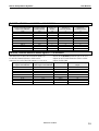
IS 6132P Interpreter Units – CU 6010/6011
The tables below shows the maximum number of IS
6132P Interpreter Sets, which can be connected to
each of the four outputs (A1, A2, B1 or B2) on a CU
6010/6011 Central Unit or on each output on an EX
6010 Extension Unit or on the output of a PS 6000.
If loudspeakers are used, then use the figures for
CM/DM 60x0P above.
Note: The number of units is dependant of how
many interpreter sets there are per booth (or
language), as there only can be one set switched ON
per language (channel).
The numbers are with no audio in loudspeaker (no
loudspeaker connected to each unit).
Length of Feeding Cable,
Type CAT5 AWG24
10m
30m
50m
100m
150m
28
Length of inter-connecting Cables,
Type CAT5 AWG24
2
2
2
2
2
m
m
m
m
m
Manual 01 18 04438
Max. number of units pr output
All ON ½ ON 1/3 ON
54
49
44
35
25
x
57
51
40
30
x
60
x
x
x
Danish Interpretation Systems
User Manual
IS 6132P w/JB 6004 and LS 6032 – CU 6010/6011
Length of Feeding Cable,
Type CAT5 AWG24
Length of cable
between booths
Number of
booths
Number of
IS 6132/ booths
Number of
LS 6032/ booths
10 m
10 m
30 m
30 m
50 m
50 m
100 m
100 m
150 m
150 m
5m
5m
5m
5m
5m
5m
5m
5m
5m
5m
19
12
17
10
15
9
11
7
8
5
4
4
4
4
4
4
4
4
4
4
0
4
0
4
0
4
0
4
0
4
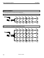
CS 6032F Channel Selector w/back light on – CU 6010/6011
The tables below shows the maximum number of
CS 6032F Channel Selectors, which can be
connected to each of the four outputs (A1, A2, B1 or
Length of Feeding Cable
Type CAT5 AWG24
Length of Inter-connecting
cable, Type CAT5 AWG24
30 m
50 m
100 m
150 m
10 m
30 m
50 m
100 m
150 m
1m
1m
1m
1m
2m
2m
2m
2m
2m
B2) on a CU 6010/6011 Central Unit or on each
output on an EX 6010 Extension Unit or on the
output of a PS 6000.
Total cable length Max. number of CS 6032 pr
output
Manual 01 18 04438
139 m
144 m
184 m
200 m
200 m
200 m
200 m
200 m
200 m
110
95
85
51
96
86
76
51
26
29
Danish Interpretation Systems
User Manual
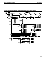
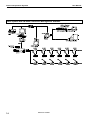
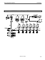
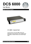
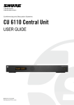
Typical schematics
The following schematics are showing various configurations:
Small conference microphone system with CU 6005
Small conference microphone system with CU 6010
30
Manual 01 18 04438
Danish Interpretation Systems
User Manual
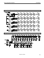
Large size conference microphone system
Microphone conference system with interpretation CU 6010
Manual 01 18 04438
31
Danish Interpretation Systems
User Manual
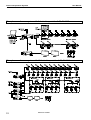
Microphone conference system with 3+1 ch. interpretation & IR, CU 6005
Microphone conference system with 15+1 ch. interpretation & IR, CU 6010
32
Manual 01 18 04438
Danish Interpretation Systems
User Manual
Various configurations with RP 6004 Repeater and PS 6000 Power Supply
Manual 01 18 04438
33
Danish Interpretation Systems
User Manual
Small system with SW 6000 Conference Management Software
34
Manual 01 18 04438
Danish Interpretation Systems
User Manual
Large system with SW 6000 Conference Management Software
Manual 01 18 04438
35
Danish Interpretation Systems
User Manual
Appendix
Technical appendix
Cabling
CAT6 can thus only be used for longer cable draws
terminating in wall outlets or patch panels.
CAT5
RS 232 Serial connection
The DCS 6000 system uses CAT5, CAT5e or
CAT6 FTP or STP cables with screened RJ45
connectors.
EIA 568-B wiring shall be used.
It is important to use only FTP or STP
(screened) cables and screened RJ45 connectors
and not UTP cable, which is unscreened.
How to wire a CAT5 (EIA 568-B) Cable:
Pin Function
1
2
3
4
5
6
7
8
Note.
Connector #1 Connector #2
In-going +
In-going +48V
0V
0V
+48V
Outgoing Outgoing +
ORG/WHT
ORG
GRN/WHT
BLU
BLU/WHT
GRN
BRN/WHT
BRN
ORG/WHT
ORG
GRN/WHT
BLU
BLU/WHT
GRN
BRN/WHT
BRN
If other colour codes are used then the four
pairs are connected as follows:
Pair 1:
Pin 1 & 2
Pair 2:
Pin 3 & 6
Pair 3:
Pin 4 & 5
Pair 4:
Pin 7 & 8
The phase of the pairs must be correct and
the wiring spec. as stated in CAT5 (EIA
568-B) have to be followed.
Note: CAT6 cables can normally only be
terminated in sockets (female) and not in cable
plugs.
36
Pin
RS232 on CU
6005/6010/6011
D9S
Pin
RS232 on PC
D9P
1 *
1 DCD
2 TxD
2 RxD
3 RxD
3 TxD
4 *
4 DTR
5 0V
5 0V
6 *
6 DSR
7 RTS
7 CTS
8 CTS
8 RTS
9
9 RI
Connect all pins in the connectors: Pin 1 to Pin 1,
Pin 2 to Pin 2, Pin 3 to Pin 3 and so on.
*
Pin 1, 4 and 6 are connected together inside
the CU 6005/6010/6011.
RS 422 Serial connection
Pin
1
2
3
4
5
6
7
8
9
Note.
Manual 01 18 04438
RS422 on CU
6005/6010/6011
D9P
RXD+(B)
RXD-(A)
TXD-(A)
TXD+(B)
0V
RTS-(A)
RTS+(B)
CTS+(B)
CTS-(A)
Pin
RS422 on PC
1
2
3
4
5
6
7
8
9
There is no standard for the pin layout of
the RS422. Please consult the manual for
the RS422 card in your PC or control
system.
Danish Interpretation Systems
User Manual
Important
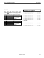
Accessories (not supplied)
Please observe that either the RS232 Serial
Connection or the RS422 Serial Connection can be
used. It is not possible to use both at the same time.
Analog Audio, Line output (XLR3 male)
Pin
Signal
Cat 5 Connection Cables (AWG24)
EC 6000-0.5 Connection Cable 0.5 m.....................10 03 12500
EC 6000-01 Connection Cable 1 m.........................10 03 13101
EC 6000-02 Connection Cable 2 m.........................10 03 13201
Cable type
EC 6000-05 Connection Cable 5 m.........................10 03 13501
1
2
3
Ground
In phase signal
Out phase signal
DIS type #2914
or 2 x 0.25 mm2
shielded.
EC 6000-10 Connection Cable 10 m.......................10 03 14102
EC 6000-20 Connection Cable 20 m.......................10 03 14202
Analog Audio, Line Input (XLR3 female)
Pin
1
2
3
Signal
Ground
In phase signal
Out phase signal
Cable type
DIS type #2914
or 2 x 0.25 mm2
shielded.
EC 6000-50 Connection Cable 50 m.......................10 03 14502
RS232 cables
EC 4010-05 Connection Cable 1 m.........................15 51 05563
EC 4010-05 Connection Cable 2 m.........................15 51 05564
EC 4010-05 Connection Cable 5 m.........................15 51 05565
EC 4010-05 Connection Cable 10 m.......................15 51 05566
Manual 01 18 04438
37
Danish Interpretation Systems
User Manual
Technical specifications
Digital Section
Connectors
Sound quality .........24 bit audio @ 32 kHz sampling frequency
DCS 6000 network chain (DCS-LAN)............................... RJ45
Analogue Section
.....................................................................2 pieces (CU 6005)
Floor output signal type ......................... electronically balanced
............................................................4 pieces (CU 6010/6011)
Max. output level....................................3.5V RMS ∼ +13 dBm
Maximum number of units to be connected to the two
outputs in total on a CU 6005 or to each chain of the four
outputs on a CU 6010/6011:
Line input signal type ............................ electronically balanced
MU 6040 Microphone Units ...................... up to 80 pieces
Nominal input level (adjustable).................................................
DM/CM 60x0P Delegate/Chairman Unit ...up to 42 pieces
...............................+6 to -30 dBm (1.55 V RMS to 25 V RMS)
IS 6132P Interpreter Set ..............................up to 54 pieces
Max. input level ...................................... +30 dBm (25V RMS)
CS 6032F Channel Selector .....................up to 110 pieces
Line input impedance ..............................................25-50 kohm
Frequency response .................................................... 50-15kHz
The actual maximum number of units depends on the
length of the feeding cable and interconnection cables
Signal to noise ratio: .................................................. >85 dBA
Line output .............................................. XLR3 male connector
Total harmonic distortion: ............................................ < 0.1%
Line input ............................................. XLR3 female connector
General
RS 232 (with hardware handshake)....................D-Sub 9 female
Power consumption .............................. max. 150W (CU 6005)
RS 422 (with hardware handshake ........................D-Sub 9 male
.......................................................max. 600W (CU 6010/6011)
................................either the RS232 or the RS422 can be used
In-rush current ...............max. 30A@115V or max. 60A@230V
System performance with CU
6005/6010/6011 as central unit
Nominal output level .......................... -8 dBm at nominal input
Mains voltage: ....................................... 100 - 240V, 50 - 60Hz
Supply voltage for units..............................................................
(for: A1 plus A2) .................................... 48V/125W (CU 6005)
(for each: A1, A2, B1, B2)............. 48V/125W (CU 6010/6011)
Max. number of conference units ............3800 (CU 6010/6011)
Max. number of conference units .......................500 (CU 6005)
Max. number of units (excl. CS) .........................................4000
Max. number of IS 6xxx in one booth.................................... 32
Temperature to guarantee specified performance
..............................5 Deg C. to 40 Deg C. (35 to 80% humidity)
Storage temp. .... -20 Deg C. to 60 Deg C. (10 to 80% humidity)
Weight ............................................................ 5.7 kg (CU 6005)
............................................................... 6.2 kg (CU 6010/6011)
Dimensions (W x H x D) .......... 425 (483) x 87 x 317 (357) mm
Dimensions in bracket are including 19” brackets
Max. number of IS 6xxx ...................................................... 150
Max. number of AO 6004/6008 ............................................. 20
Max. number of CS 6032 ...........................practically unlimited
Max. number of languages ................................... 16 (CU 6005)
.................................................................... 31 (CU 6010/6011)
Max number of open microphones........................................... 8
Slot dimensions (W x H x D)..... 180 x 38 x 120 mm (CU 6005)
Accessories supplied...............................................User manual
The DCS 6000 system conforms to all relevant standards e.g. IEC 914, ISO 4043, and ISO 2603
.................................................................................Mains cable
.......................................................... 5 pieces termination plugs
38
Specifications are subject to change without notice.
Manual 01 18 04438
Danish Interpretation Systems
User Manual
Manual 01 18 04438
39