1
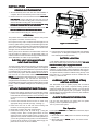
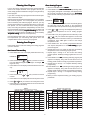
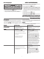
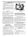
1F80-361
Programmable Electronic Digital Thermostat
INSTALLATION AND
OPERATION INSTRUCTIONS
Oper
a tor
ve these instr
uctions ffor
or futur
e use!
Opera
tor:: Sa
Sav
instructions
future
FAILURE TO READ AND FOLLOW ALL INSTRUCTIONS CAREFULLY
BEFORE INSTALLING OR OPERATING THIS CONTROL COULD CAUSE
PERSONAL INJURY AND/OR PROPERTY DAMAGE.
DESCRIPTION
Your new White-Rodgers 5-Day/1-Day/1-Day Digital Thermostat uses the technology of a solid-state microcomputer to
provide precise time/temperature control. This thermostat offers
you the flexibility to design heating and cooling programs that fit
your needs.
Features:
• Separate 5-day (weekday), 1-day (Sat) and 1-day (Sun) programming with four separate time/temperature periods per day
• Simultaneous heat and cool program storage
• Preprogrammed temperature control
• Backlit display
• LCD continuously displays setpoint, and alternately displays time and room temperature
•
•
•
•
•
•
•
•
Temperature override until next program period
Manual program override (HOLD temperature)
Temporary HOLD
°F/°C convertibility
Temperature range 45° to 90°F
RC, RH, C, W, Y, G , O and B terminals
Optional C terminal (Dual Power option)
B and O terminals for single stage heat pumps (no auxiliary
heat) or damper operation
• Program storage in case of power loss
• 2 “AA” alkaline batteries included
PRECAUTIONS
This thermostat is intended for use with a low voltage system; do
not use this thermostat with a line voltage system. If in doubt
about whether your wiring is millivolt, line, or low voltage, have
it inspected by a qualified heating and air conditioning contractor
or electrician.
Do not exceed the specification ratings.
All wiring must conform to local and national electrical codes and
ordinances.
This control is a precision instrument, and should be handled
carefully. Rough handling or distorting components could cause
the control to malfunction.
! WARNING
Do not use on circuits exceeding specified voltage.
Higher voltage will damage control and could cause
shock or fire hazard.
Do not short out terminals on gas valve or primary control
to test. Short or incorrect wiring will damage thermostat
and could cause personal injury and/or property damage.
Thermostat installation and all components of the system shall conform to Class II circuits per the NEC code.
! CAUTION
To prevent electrical shock and/or equipment damage,
disconnect electric power to system at main fuse or
circuit breaker box until installation is complete.
SPECIFICATIONS
ELECTRICAL DATA
APPLICATIONS
Electrical Rating:
8 to 30 VAC 50/60 Hz. or D.C.
0.05 to 1.0 Amps (Load per terminal)
1.5 Amps Maximum Total Load (All terminals combined)
THERMAL DATA
Setpoint Temperature Range:
45°F to 90°F (7°C to 32°C)
Operating Ambient Temperature Range:
32°F to 105°F
Operating Humidity Range:
0 to 90% RH (non-condensing)
Shipping Temperature Range:
-4°F to 149°F
For use with:
• Standard heat/cool or heat only systems
• Electric heat systems
• Gas or oil fired systems
• Gas systems with intermittent ignition devices (I.I.D.)
and/or vent dampers
• Hydronic (hot water or steam) systems
• Single-stage heat pump systems (no auxiliary heat)
• Millivolt systems
DO NOT USE WITH:
• Multi-stage systems
• Systems exceeding 30 VAC and 1.5 amps
• 3-wire zoned hydronic heating systems
White-Rodgers is a division
of Emerson Electric Co.
www.white-rodgers.com
PART NO. 37-6621C
Replaces 37-6621B
0745
INSTALLATION
REMOVE OLD THERMOSTAT
Screw anchors
1. Shut off electricity at the main fuse box until installation is
complete. Ensure that electrical power is disconnected.
2. Remove the front cover of the old thermostat. With wires
still attached, remove wall plate from the wall. If the old
thermostat has a wall mounting plate, remove the thermostat and the wall mounting plate as an assembly.
3. Identify each wire attached to the old thermostat using
the labels enclosed with the new thermostat.
4. Disconnect the wires from old thermostat one at a time. DO
NOT LET WIRES FALL BACK INTO THE WALL.
5. Install new thermostat using the following procedures.
ATTENTION!
Mounting
holes
This product does not contain mercury. However, this product
may replace a unit which contains mercury.
Mounting
holes
Electric/Gas
switch
Do not open mercury cells. If a cell becomes damaged, do not
touch any spilled mercury. Wearing nonabsorbent gloves, take
up the spilled mercury with sand or other absorbent material and
place into a container which can be sealed. If a cell becomes
damaged, the unit should be discarded.
Figure 1. Thermostat Base
Mercury must not be discarded in household trash. When the
unit this product is replacing is to be discarded, place in a
suitable container and return to White-Rodgers at 2895 Harrison
Street, Batesville, AR 72501 for proper disposal.
6. Push excess wire into wall and plug hole with a fire-resistant
material (such as fiberglass insulation) to prevent drafts
from affecting thermostat operation.
ELECTRIC HEAT OR SINGLE-STAGE
HEAT PUMP SYSTEMS
2 "AA" alkaline batteries are included in the thermostat at the
factory with a battery tag to prevent power drainage. You must
remove the battery tag to engage the batteries
batteries.
BATTERY LOCATION
This thermostat is configured from the factory to operate a heat/
cool, fossil fuel (gas, oil, etc.), forced air system. It is configured
correctly for any system that DOES NOT require the thermostat
to energize the fan on a call for heat. If your system is an electric
heat or heat-pump system that REQUIRES the thermostat to
turn on the fan on a call for heat, locate the ELECTRIC/GAS
switch on the back of the thermostat (see fig. 1) and switch it to
the ELECTRIC position. This will allow the thermostat to
energize the fan immediately on a call for heat. If you are unsure
if the heating/cooling system requires the thermostat to control
the fan, contact a qualified heating and air conditioning service
person.
If “BATT” is displayed, the batteries are low and should be
replaced. For best results, replace all batteries with new premium brand alkaline batteries such as Duracell® or Energizer®.
To replace batteries, install the batteries along the top of the
base (see Fig. 1). The batteries must be installed with the
positive (+) end to the left.
HYDRONIC (HOT WATER OR STEAM)
HEATING SYSTEMS
This thermostat is set to operate properly with a forced-air
heating system. If you have a hydronic heating system (a
system that heats with hot water or steam), you must set the
thermostat to operate properly with your system. Change the
second option in the configuration menu to SL (see CONFIGURATION MENU, page 4).
ATTACH THERMOSTAT BASE TO WALL
1. Remove the packing material from the thermostat. Gently
pull the cover straight off the base. Forcing or prying on the
thermostat will cause damage to the unit. If necessary, move
the electric heat switch (see ELECTRIC HEAT SYSTEMS
SYSTEMS,
above).
2. Connect wires beneath terminal screws on base using
appropriate wiring schematic (see figs. 2 through 7).
3. Place base over hole in wall and mark mounting hole
locations on wall using base as a template.
4. Move base out of the way. Drill mounting holes.
5. Fasten base loosely to wall, as shown in fig. 1, using two
mounting screws. Place a level against bottom of base,
adjust until level, and then tighten screws. (Leveling is for
appearance only and will not affect thermostat operation.) If
you are using existing mounting holes, or if holes drilled are
too large and do not allow you to tighten base snugly, use
plastic screw anchors to secure subbase.
CHECK THERMOSTAT OPERATION
If at any time during testing your system does not operate
properly, contact a qualified service person.
Turn on power to the system.
Fan Operation
If your system does not have a G terminal connection, skip to
System.
Heating System
1. Move FAN switch to ON position. The blower should begin
to operate.
2. Move FAN switch to AUTO position. The blower should
stop immediately.
2
JUMPER
WIRE
C‡
C‡
THERMOSTAT
B
O
Y
G
W
RC
THERMOSTAT
B
O
G
W
RC
RH
SYSTEM
RH
SYSTEM
Fan
Relay
Y
Heating
System
Cooling
System
Fan
Relay
Hot
Heating
System
24 VAC
120 VAC
Neutral
Hot
24 VAC
NOTE
HEATING
TRANSFORMER
120 VAC
Neutral
For 2-wire Heat only,
attach to RH and W
Hot
TRANSFORMER
24 VAC
Figure 2. Typical wiring diagram for
heat only, 3-wire, single transformer systems
120 VAC
Neutral
COOLING TRANSFORMER
Figure 5. Typical wiring diagram for
heat/cool, 5-wire, two-transformer systems
JUMPER
WIRE
C‡
THERMOSTAT
B
Y
O
G
W
RC
RH
SYSTEM
Cooling
System
Fan
Relay
JUMPER
WIRE
C‡
Hot
24 VAC
JUMPER
WIRE
THERMOSTAT
B
Y
O
G
W
RC
RH
SYSTEM
120 VAC
Reversing Compressor Fan
Valve*
Contactor Relay
Neutral
TRANSFORMER
Hot
24 VAC
Figure 3. Typical wiring diagram for
cool only, 3-wire, single transformer systems
* Reversing valve is energized when the
system switch is in the COOL position
120 VAC
Neutral
TRANSFORMER
Figure 6. Typical wiring diagram for heat pump
with reversing valve energized in COOL
NOTE
RED jumper wire (provided with thermostat) must be
connected between thermostat RH and RC terminals
for proper thermostat operation with this system.
C‡
JUMPER
WIRE
JUMPER
WIRE
THERMOSTAT
B
O
Y
G
W
RC
RH
C‡
SYSTEM
JUMPER
WIRE
THERMOSTAT
B
O
Y
G
W
RC
RH
SYSTEM
Cooling
System
Fan
Relay
Heating
System
Reversing Compressor Fan
Valve*
Contactor Relay
Hot
24 VAC
Hot
24 VAC
120 VAC
* Reversing valve is energized when the
system switch is in the HEAT position
Neutral
TRANSFORMER
Figure 7. Typical wiring diagram for heat pump
with reversing valve energized in HEAT
Figure 4. Typical wiring diagram for
heat/cool, 4-wire, single transformer systems
‡
120 VAC
Neutral
TRANSFORMER
The 24 Volt neutral connection to terminal C on the thermostat is not required if the batteries are replaced once a year
with fresh premium brand alkaline batteries.
Heating System
Cooling System
▲! CAUTION
1. Move SYSTEM switch to HEAT position. If the heating
system has a standing pilot, be sure to light it.
To prevent compressor and/or property damage, if the
outdoor temperature is below 50°F, DO NOT operate
the cooling system.
2. Press
to adjust thermostat setting above room temperature. The heating system should begin to operate.
3. Press
to adjust temperature setting below room temperature. The heating system should stop operating.
1. Move SYSTEM switch to COOL position.
to adjust thermostat setting below room tempera2. Press
ture. The blower should come on immediately on high
speed, followed by cold air circulation
3. Press
to adjust temperature setting above room temperature. The cooling system should stop operating.
3
OPERATION
Before you begin programming your thermostat, you should be
familiar with its features and with the display and the location
and operation of the thermostat buttons. Your thermostat consists of two parts: the thermostat cover and the base
base. To remove
the cover, pull it straight out from the base. To replace the cover,
line up the cover with the base and press until the cover snaps
onto the base.
The Thermostat Buttons and Switches
1 Raises temperature setting.
2 Lowers temperature setting.
3 TIME button.
4 PRGM (program) button.
5 RUN (run program) button.
6 HOLD temperature button.
ON
ON, AUTO
AUTO).
7 FAN switch (ON
COOL
COOL, OFF
OFF, HEAT
HEAT).
8 SYSTEM switch (COOL
The Display
Press HOLD to change to the next menu item or press TIME to
go backwards to the previous item in the menu. To exit the menu
and return to the program operation, press RUN. If no keys are
pressed within fifteen minutes, the thermostat will revert to
normal operation.
9 Indicates day of the week.
10 Flame icon ( ) is displayed when the SYSTEM switch is in
the HEAT position. Snowflake icon ( )is displayed (nonflashing) when the SYSTEM switch is in the COOL position.
Snowflake is displayed (flashing) if the thermostat is in
lockout mode to prevent the compressor from cycling too
quickly.
11 Displays “BATT” when the 2 "AA" batteries are low and
should be replaced. Only “BATT” and “LO” in the minutes
field are displayed when batteries are low with no system
power.
12 Alternately displays current time and temperature. Displays “LO” in the minutes field when batteries are low.
13 The word “HOLD” is displayed when the thermostat is in the
HOLD mode. “HOLD” is displayed flashing when the
thermostat is in a temporary HOLD Mode.
14 Displays currently programmed set temperature (this is
blank when SYSTEM switch is in the OFF position).
15 Displays “FLTR” when the system has run for the programmed filter time period as a reminder to change or clean
your air filter.
1) Select Temporary Hold Time - The thermostat can hold any
temperature you set it to for the amount of time you select on
this option. Your choices are 0:00 to 8:00 hours in 15 minute
increments. 0:00 disables the function
Example:
1. You have selected 3:00 hours for the Temporary Hold
time period.
2. With the thermostat set to Heat or Cool, press HOLD for
approximately five seconds until HOLD time (3:00
indicating 3 hours) appears as a setting reminder.
3. After releasing the button, “HOLD” on the display will
blink.
or
to set the temperature to your preference.
4. Use
The thermostat will maintain this temperature setting for
3 hours with “HOLD” blinking to remind you it is in
Temporary Hold. After 3 hours the thermostat will go
back to the program temperature and “HOLD” will no
longer blink or display.
2) Select FA or SL (Fast or Slow) Heating Cycle Rate - The
FA setting is frequently used for gas, oil or electric heat. The
SL setting produces a longer heating cycle which is normally for hot water or steam (hydronic) systems. Both
settings produce very accurate temperature control and
can be set to your personal preference. FA cycles the
system just under 1°F and the SL setting cycles at approximately 1.5°F.
3) Select backlit display - The display backlight improves
display contrast in low lighting conditions. Selecting backlight ON will keep the light on for a short period of time after
any key is pressed. Selecting OFF will keep the light off.
CONFIGURATION MENU
The configuration menu allows you to set certain thermostat
operating characteristics to your system or personal requirements.
Press RUN to make sure the thermostat is in the run program
mode, then press PRGM and RUN at the same time to enter the
configuration menu. The display will show the first item in the
configuration menu.
The configuration menu table summarizes the configuration
options. An explanation of each option follows.
4
Configuration Menu
Step
Press Button(s)
1
PRGM
and RUN
2
HOLD*
Displayed (Factory Default) Press
HOLD
(0:00)
or
to select:
0 to 8 hrs (in
15 minute increments)
COMMENTS
Select temporary Hold time
Select FA or SL (Fast or Slow) heating cycle rate
SL
(FA)
3
HOLD*
d-L
(ON)
OFF
Select display backlight OFF or ON
4
HOLD*
E
(ON)
OFF
Select Energy Management Recovery OFF or ON
5
HOLD*
Filter
(000)
0 to 1950 hours
(in 50 hour increments)
6
HOLD*
LOC
(OFF)
ON
7
HOLD*
0 HI
(0)
4 LO to
4 HI
8
HOLD*
(F)
C
9
RUN
Select filter replacement run time
Select compressor lockout OFF or ON
Select temperature display adjustment higher or lower
Select temperature display to F or C
Returns to normal operation
* Press HOLD to advance to next item or TIME to move backwards to previous item
OPERATING FEATURES
4) Select Energy Management Recovery OFF or ON Energy Management Recovery (EMR) causes the thermostat to start heating or cooling early to make the building
temperature reach the program setpoint at the time you
specify. Heating will start 5 minutes early for every 1° of
temperature required to reach setpoint.
Example: You select EMR and have your heating programmed to 65° at night and 70° at 7 AM. If the building
temperature is 65° the difference between 65° and 70° is
5°. Allowing 5 minutes per degree the thermostat setpoint
will change to 70° at 6:35 AM. Cooling allows more time per
degree because it takes longer to reach temperature.
5) Select filter replacement run time - The thermostat will
display “FLTR” after a set time of operation. This is a
reminder to change or clean your air filter. This time can be
set from 0 to 1950 hours in 50 hour increments. A selection
of 000 will cancel this feature. When “FLTR” is displayed,
you can clear it by pressing HOLD and RUN at the same
time. This resets the timer and starts counting the hours
until the next filter change. Changing the time in the menu
also resets the timer.
6) Select Compressor Lockout LOC OFF or ON - Selecting
LOC ON will cause the thermostat to wait 5 minutes before
turning on the compressor if the heating and cooling system loses power. It will also wait 5 minutes minimum
between cooling cycles. This is intended to help protect the
compressor from short cycling. Some newer compressors
already have a time delay built in and do not require this
feature. Your compressor manufacturer can tell you if the
feature is already present in their system. When the compressor time delay occurs it will flash the (snowflake icon)
for about five minutes then turn on the compressor.
7) Select Temperature Display Adjustment 4 LO to 4 HI Allows you to adjust the room temperature display 4° higher
or lower. Your thermostat was accurately calibrated at the
factory but you have the option to change the display
temperature to match your previous thermostat.
8) Select F° or C° Readout - Changes the display readout to
Centigrade or Fahrenheit as required.
Now that you are familiar with the thermostat buttons and
display, read the following information to learn about the many
features of the thermostat.
• SIMULTANEOUS HEATING/COOLING PROGRAM
STORAGE — When programming, you can enter both
your heating and cooling programs at the same time. There
is no need to reprogram the thermostat at the beginning of
each season.
or
until the
• TEMPERATURE OVERRIDE — Press
display shows the temperature you want. The thermostat
will override current programming and keep the room
temperature at the selected temperature until the next
program period begins. Then the thermostat will automatically revert to the program.
• HOLD TEMPERATURE — The thermostat can hold any
temperature within its range for an indefinite period without
reverting to the programmed temperature. Momentarily
press HOLD button. “HOLD” will be displayed. Then choose
or
. The
the desired temperature by pressing
thermostat will hold the room temperature at the selected
setting until you press RUN button to start program operation again.
• CONFIGURATION MENU — Allows you to customize
certain thermostat options.
PROGRAMMING YOUR THERMOSTAT
This section will help you plan your thermostat’s program to
meet your needs. For maximum comfort and efficiency, keep
the following guidelines in mind when planning your program.
• When heating (cooling) your building, program the
temperatures to be cooler (warmer) when the building is
vacant or during periods of low activity.
• During early morning hours, the need for cooling is
usually minimal.
5
Enter Heating Program
Planning Your Program
1. Move the SYSTEM switch to HEAT
HEAT.
MO TU WE TH FR
2. Press PRGM once. “MO
FR” (indicating weekday program) will appear in the display. Also displayed are
the currently programmed start time for the 1st heating
period and the currently programmed temperature (flashing).
Look at the factory preprogrammed times and temperatures
shown in the sample schedule. If this program will suit your
needs, simply press the RUN button to begin running the factory
preset program.
If you want to change the preprogrammed times and temperatures, follow these steps.
MO TU WE TH FR
Determine the time periods and temperatures for your weekday
and weekend programs. You must program four periods for
both the weekday and weekend program. However, you may
use the same heating and cooling temperatures for consecutive
time periods. You can choose start times, heating temperatures, and cooling temperatures independently for both weekday and weekend programs (for example, you may select 5:00
AM and 70° as the weekday 1st period heating start time and
temperature, and also choose 7:00 AM and 76° as the weekday
1st period cooling start time and temperature).
EXAMPLE:
This display window shows that for the 1st weekday period,
the start time is 6:00 AM, and 68° is the programmed
temperature (this example reflects factory preprogramming).
3. Press
or
to change the displayed temperature to
your selected temperature for the 1st heating program
period.
4. Press TIME once (the programmed time will flash). Press
Use the following table to plan your program time periods and
the temperatures you want during each period. Fill in the
complete table to have a record of your programs.
or
until your selected time appears. The time will
change in 15 minute increments. When your selected time
is displayed, press TIME again to return to the change
temperature mode.
5. Press PRGM once. The currently programmed start time
and setpoint temperature for the 2nd heating program
period will appear.
6. Repeat steps 3 and 4 to select the start time and heating
temperature for the 2nd heating program period.
7. Repeat steps 3 through 5 for the 3rd and 4th heating
program periods. Weekday heating programs are now complete.
SA
8. Press PRGM once. “SA
SA” (indicating Saturday program) will
appear in the display, along with the start time for the 1st
heating period and the currently programmed temperature.
9. Repeat steps 3 through 7 to complete Saturday heating
programming.
SU
10.Press PRGM once. “SU
SU” (indicating Sunday program) will
appear in the display, along with the start time for the 1st
heating period and the currently programmed temperature.
11.Repeat steps 3 through 7 to complete Sunday heating
programming.
12.When you have completed entering your heating program,
press RUN.
Entering Your Program
Follow these steps to enter the heating and cooling programs
you have selected.
Set Current Time and Day
1. Press TIME button once. The display will show the hour only.
EXAMPLE:
PM
2. Press and hold either
or
until you reach the correct
AM begins at midnight; PM
hour and AM/PM designation (AM
begins at noon).
3. Press TIME once. The display window will show the minutes
only.
EXAMPLE:
4. Press and hold either
or
until you reach the correct
minutes.
5. Press TIME once. The display will show the day of the week.
6. Press
or
AM
until you reach the current day of the week.
7. Press RUN once. The display will show the correct time and
room temperature alternately.
SAMPLE
Heating/Cooling Schedule Plan (Factory Program)
Period
Temperature
Start
Time
Temperature
Start
Time
Temperature
1ST
6:00 AM
70°F
6:00 AM
70°F
6:00 AM
70°F
2ND
8:00 AM
62°F
8:00 AM
62°F
8:00 AM
62°F
3RD
5:00 PM
70°F
5:00 PM
70°F
5:00 PM
70°F
4TH
10:00 PM
62°F
10:00 PM
62°F
10:00 PM
62°F
1ST
6:00 AM
78°F
6:00 AM
78°F
6:00 AM
78°F
2ND
8:00 AM
85°F
8:00 AM
85°F
8:00 AM
85°F
3RD
5:00 PM
78°F
5:00 PM
78°F
5:00 PM
78°F
4TH
10:00 PM
82°F
10:00 PM
82°F
10:00 PM
82°F
1ST
HEAT
HEAT
SUNDAY (1 DAY)
Start
Time
Period
COOL
SATURDAY (1 DAY)
2ND
3RD
4TH
1ST
COOL
WEEKDAY (5 DAY)
Heating/Cooling Schedule Plan
SATURDAY (1 DAY)
WEEKDAY (5 DAY)
2ND
3RD
4TH
6
Start
Time
Temperature
Start
Time
Temperature
SUNDAY (1 DAY)
Start
Time
Temperature
Enter Cooling Program
CHECK YOUR PROGRAMMING
! CAUTION
Follow these steps to check your thermostat programming one
final time before beginning thermostat operation.
If the outside temperature is below 50°F, disconnect
power to the cooling system before programming.
Energizing the air conditioner compressor during cold
weather may cause personal injury or property damage.
1. Move SYSTEM switch to HEAT position.
2. Press PRGM to view the 1st weekday heating period time
and temperature. Each time you press PRGM, the next
heating period time and temperature will be displayed in
sequence for weekday, then weekend program periods (you
may change any time or temperature during this procedure).
3. Press RUN.
4. Move SYSTEM switch to COOL position.
5. Repeat step 2 to check cooling program.
6. Move SYSTEM switch to HEAT or COOL and press RUN to
begin program operation.
1. Move SYSTEM switch to COOL position.
2. Follow the procedure for entering your cooling program,
using your selected cooling times and temperatures.
YOUR THERMOSTAT IS NOW COMPLETELY PROGRAMMED AND
READY TO PROVIDE MAXIMUM COMFORT AND EFFICIENCY!
TROUBLESHOOTING
Reset Operation
If a voltage spike or static discharge blanks out the display or
causes erratic thermostat operation you can reset the thermo-
program. If the thermostat has power, has been reset and still
does not function correctly contact your heating/cooling service person or place of purchase.
stat by pressing
,
and TIME at the same time. This also
resets the factory defaults to the configuration menu and
Batteries
For optimum performance, we recommend replacing batteries
once a year with fresh "AA" alkaline batteries.
Symptom
Possib
le Cause
ossible
Corrective Action
No Heat/No Cool/No Fan
(common problems)
1. Blown fuse or tripped circuit breaker.
2. Furnace power switch to OFF.
3. Furnace blower compartment door or
panel loose or not properly installed.
1. Pilot light not lit.
T.
2. SYSTEM Switch not set to HEA
HEAT
Replace fuse or reset breaker.
Turn switch to ON.
Replace door panel in proper position to engage
safety interlock or door switch.
Re-light pilot.
Set SYSTEM Switch to Heat and raise setpoint
above room temperature.
Verify thermostat and system wires are securely
attached.
Many furnaces have safety devices that shut the
system down when a lock-out condition occurs.
If the heat works intermittently contact the furnace
manufacturer or local service person for assistance.
T and raise
Diagonistic: Set SYSTEM Switch to HEA
HEAT
the setpoint above room temperature. Within a few
seconds the thermostat should make a soft click
sound. This sound usually indicates the thermostat
is operating properly. If the thermostat does not
click, try the reset operation listed above. If the
thermostat does not click after being reset contact
your heating and cooling service person or place
of purchase for a replacement. If the thermostat
clicks, contact the furnace manufacturer or a
service person to verify the heating system is
operating correctly.
Set SYSTEM Switch to COOL and lower setpoint
below room temperature.
Verify thermostat and system wires are securely
attached.
Same procedure as diagnostic for No Heat
condition except set the thermostat to COOL and
lower the setpoint below the room temperature.
There may be up to a five minute delay before
the thermostat clicks in Cooling if the compressor
lock-out option is selected in the configuration
menu (Item 6).
No Heat
3. Loose connection to thermostat or system.
4. Furnace Lock-Out Condition. Heat may also
be intermittent.
5. Heating System requires service or
thermostat requires replacement.
No Cool
1. SYSTEM Switch not set to COOL
2. Loose connection to thermostat or system.
3. Cooling System requires service or thermostat
requires replacement.
7
TROUBLESHOOTING
Symptom
Possib
le Cause
ossible
Corrective Action
Heat, Cool or Fan Runs Constantly.
1.
2.
3.
4.
Furnace Cycles Too Fast or Too Slow
(narrow or wide temperature swing)
1. The location of the thermostat and/or the size
of the Heating System may be influencing the
cyclerate.
Cooling Cycles Too Fast or Too Slow
(narrow or wide temperature swing)
Thermostat Setting and Thermometer
Disagree
1. The location of the thermostat and/or the size
of the Cooling System may be influencing the
cycle rate.
1. Thermostat thermometer setting requires
adjustment.
Clock Loses or Gains Time
1. Loss of power to thermostat and low batteries.
Check each wire connection to verify they are
not shorted or touching together. No bare wire
should stick out from under terminal screws.
Try resetting the thermostat. If the condition
persists the manufacturer of your system
or service person can instruct you on how
to test the Heat/Cool system for correct
operation. If the system operates correctly,
replace the thermostat.
Item 2 in the Configuration Menu is the adjustment
that controls the cycle rate. If an acceptable cycle
rate is not achieved using the FA (Fast) or SL
(Slow) adjustment contact a local service person for
additional suggestions.
The cycle rate for cooling is fixed and can not be
adjusted. Contact a local service person for
suggestions.
The thermometer can be adjusted +/- 4 degrees as
listed in item 7 of the Configuration Menu. No other
adjustment is possible.
The thermostat will maintain its program in memory
even with no power/no batteries but the clock time
will be incorrect when power is restored. See No
Heat/No Cool/No Fan (common problems) above
for items to check in the system.
See Configuration Menu (Item 4).
Check current clock and program settings including
the AM or PM designations for each time period.
If a voltage spike or static discharge occurs use the
Reset Operation listed above.
Replace batteries and check heat/cool system for
proper operation. If a voltage spike or static discharge
occurs use the Reset Operation listed above.
FAN Switch set to Fan ON.
Possible short in wiring.
Possible short in thermostat.
Possible short in Heat/Cool/Fan system.
Heat or Cool Starts Early
1. EMR activated
Thermostat Does Not Follow Program 1. AM or PM set incorrectly in program.
2. AM or PM set incorrectly on the clock.
3. Voltage spike or static discharge.
Blank Display and/or Keypad Not
Responding
1. Loss of power and dead batteries.
2. Voltage Spike or Static Discharge.
HOMEOWNER HELP LINE: 1-800-284-2925
The Emerson logo is a
trademark and service mark
of Emerson Electric Co.
St. Louis, Missouri
Markham, Ontario
www.white-rodgers.com
1F80-361
Termostato digital electrónico programable
INSTRUCCIONES DE
INSTALACIÓN Y OPERACIÓN
Sr. operador: ¡Conserve estas instrucciones para consultarlas en cualquier momento!
EL NO LEER Y SEGUIR CON CUIDADO TODAS LAS INSTRUCCIONES
ANTES DE INSTALAR O UTILIZAR ESTE CONTROL PODRÍA CAUSAR
LESIONES PERSONALES Y/O DAÑOS MATERIALES.
DESCRIPCIÓN
Su nuevo termostato digital programable a 5 días/1 día/1 día de WhiteRodgers utiliza la tecnología de una microcomputadora de estado sólido
para proporcionar un control preciso del tiempo y de la temperatura. Este
termostato le ofrece la flexibilidad de diseñar programas de calefacción
y refrigeración adecuados a sus necesidades.
Características:
• Programación separada de 5 días (días de semana), 1 día (sábado) y
1 día (domingo) con cuatro períodos de tiempo/temperatura separados
por día
• Almacenamiento simultáneo de programa de calefacción y
refrigeración
• Control de temperatura preprogramada
• Pantalla con luz de fondo
• La pantalla de LCD muestra de forma permanente la temperatura de
referencia y, de forma alterna, la hora y la temperatura ambiente
Este termostato está diseñado para ser utilizado con un sistema de bajo
voltaje; no utilice este termostato con un sistema de voltaje de línea.
Si tiene dudas acerca de si su conexión eléctrica es milivoltio, de línea
o de bajo voltaje, hágala inspeccionar por un técnico especializado
en equipos de calefacción y aire acondicionado o por un electricista
autorizado.
No exceda los valores nominales especificados.
Todas las conexiones eléctricas deben cumplir con los códigos y
reglamentaciones locales y nacionales.
Este control es un instrumento de precisión y debe manipularse con
cuidado. La manipulación descuidada o la distorsión de los componentes
podrían hacer que el control no funcionara correctamente.
! ¡PRECAUCIÓN!
▲
Para evitar descargas eléctricas y/o daños al equipo,
desconecte la alimentación eléctrica en la caja de
fusibles o disyuntores principal hasta que haya
finalizado la instalación del sistema.
DATOS ELÉCTRICOS
Rango de temperatura de referencia:
45°F a 90°F (7°C a 32°C)
Rango de temperatura ambiente operativa:
32°F a 105°F
Rango de humedad operativa:
0 a 90% HR (sin condensación)
Rango de temperatura de transporte:
-4°F a 149°F
PRECAUCIONES
▲
! ¡ADVERTENCIA!
No utilizar en circuitos que excedan el voltaje
especificado ya que los voltajes más altos dañarán
el control y pueden causar riesgos de electrocución
o incendio.
No cortocircuite las terminales de la válvula de gas ni
del control principal para probarlos. Un cortocircuito o
una conexión incorrecta dañarán el termostato y podría
causar lesiones personales y/o daños materiales.
La instalación del termostato y de todos los
componentes del sistema debe ajustarse a las normas
del código NEC para los circuitos Clase II.
APLICACIONES
Características eléctricas:
8 a 30 VCA 50/60 Hz o CC
0.05 a 1.0 A (carga por terminal)
1.5 A de carga total máxima (todas las terminales combinadas)
DATOS TÉRMICOS
• Omisión de la temperatura programada hasta el siguiente
período de programación
• Omisión del programa manual (MANTENER temperatura)
• MANTENER temperatura de forma temporal
• Convertibilidad de°F a °C
• Rango de temperatura de 45° a 90°F
• Terminales RC, RH, C, W, Y, G, O y B
• Terminal C opcional (opción de doble alimentación)
• Terminales B y O para bombas de calor de una sola etapa
(sin calor auxiliar) u operación de amortiguación
• Almacenamiento de programa en caso de cortes de energía
eléctrica
• Incluye 2 pilas alcalinas “AA”
ESPECIFICACIONES
Para utilizar con:
• Sistemas de calor/frío o sólo calor estándar
• Sistemas de calor eléctricos
• Sistemas de gas o aceite
• Sistemas de gas con dispositivos de encendido intermitente
(I.I.D.) y/o amortiguadores de ventilación
• Sistemas hidrónicos (agua caliente o vapor)
• Sistemas de bomba de calor de una sola etapa (sin calor
auxiliar)
• Sistemas milivoltios
NO UTILIZAR CON:
• Sistemas multietapa
• Sistemas que exceden los 30 VCA y 1.5 A
• Sistemas de calefacción hidrónicos zonificados de 3 cables
White-Rodgers es una división
de Emerson Electric Co.
www.white-rodgers.com
N° DE PIEZA 37-6621C
Reemplaza 37-6621B
0745
INSTALACIÓN
RETIRE EL TERMOSTATO VIEJO
Anclajes plásticos
1. Apague la electricidad en la caja de fusibles principal hasta que
haya finalizado la instalación. Asegúrese de que la alimentación
eléctrica esté desconectada.
2. Retire la cubierta delantera del termostato viejo. Con los cables
aún conectados, retire la placa de la pared. Si el termostato viejo
tiene una placa de montaje sobre pared, retire el termostato y la
placa juntos.
3. Identifique cada uno de los cables conectados al termostato viejo
usando las etiquetas incluidas con el nuevo termostato.
4. Desconecte los cables del termostato viejo de a uno a la vez. NO
DEJE QUE LOS CABLES VUELVAN A INTRODUCIRSE EN LA
PARED.
5. Instale el termostato nuevo siguiendo el procedimiento indicado a
continuación.
Orificios
de montaje
¡ATENCIÓN!
Interruptor
eléctrico/de gas
Este producto no contiene mercurio. No obstante, puede reemplazar
una unidad que sí contiene mercurio.
Orificios
de montaje
Figura 1. Base del termostato
No abra las celdas de mercurio. En el caso de que una celda se
dañe, no toque el mercurio derramado. Usando un par de guantes no
absorbentes, recoja el mercurio derramado con arena u otro material
absorbente y viértalo en un recipiente que pueda sellarse. Si se daña
una celda, debe desecharse la unidad.
6. Empuje el cable que sobresale hacia el interior de la pared y tape el
orificio con un material ignífugo (como aislamiento de fibra de vidrio)
para evitar que las corrientes de aire afecten el funcionamiento del
termostato.
El mercurio no debe desecharse con los residuos domésticos. Para
desechar la unidad que será reemplazada por este equipo, colóquela
en un recipiente adecuado y envíela a White-Rodgers a 2895 Harrison
Street, Batesville, AR 72501 para su eliminación adecuada.
UBICACIÓN DE LAS PILAS
SISTEMAS DE CALOR ELÉCTRICOS O DE
BOMBA DE CALOR DE UNA SOLA ETAPA
El termostato viene de fábrica con 2 pilas alcalinas “AA” unidas entre
sí para evitar que se descarguen. Debe retirar la tira de papel para
poder enganchar las pilas en su lugar.
Este termostato está configurado de fábrica para operar un sistema de
aire forzado con combustible fósil (gas, aceite, etc.) de calor/frío. Está
correctamente configurado para cualquier sistema que NO requiera
que el termostato energice el ventilador en una llamada de calor. Si su
sistema es un sistema eléctrico o de bomba de calor que REQUIERE
que el termostato encienda el ventilador en una llamada de calor,
ubique el interruptor ELECTRIC/GAS (vea la figura 1) y colóquelo
en la posición ELECTRIC. Esto permitirá al termostato energizar el
ventilador inmediatamente en una llamada de calor. Si no está seguro
si el sistema de calefacción/refrigeración requiere que el termostato
controle el ventilador, póngase en contacto con un servicio técnico de
calefacción y aire acondicionado calificado.
Si aparece el mensaje “BATT”, significa que las pilas tienen poca carga
y deben cambiarse. Para obtener resultados óptimos, cambie todas las
pilas por pilas alcalinas nuevas de alguna marca líder como Duracell®
o Energizer®. Para cambiar las pilas, instálelas a lo largo de la parte
superior de la base (vea la figura 1). Las pilas deben instalarse con los
polos positivos (+) hacia la izquierda.
SISTEMAS DE CALEFACCIÓN HIDRÓNICOS
(AGUA CALIENTE O VAPOR)
Este termostato está configurado para funcionar en forma adecuada con un
sistema de calefacción de aire forzado. Si tiene un sistema de calefacción
hidrónico (un sistema que genera calor con agua caliente o vapor), debe
configurar el termostato para que funcione de manera adecuada con su
sistema. Cambie la segunda opción en el menú de configuración a SL
(vea el MENÚ DE CONFIGURACIÓN en la página 4).
FIJE LA BASE DEL
TERMOSTATO A LA PARED
1. Retire el material de embalaje del termostato. Tire suavemente
de la cubierta para separarla de la base. Si fuerza o hace palanca
sobre el termostato dañará la unidad. Si es necesario, mueva el
interruptor de calor eléctrico (vea la sección SISTEMAS DE CALOR
ELÉCTRICOS más arriba).
VERIFIQUE EL FUNCIONAMIENTO DEL
TERMOSTATO
2. Conecte los cables que se encuentran debajo de los tornillos
terminales a la base consultando el esquema de conexiones
apropiado (vea las figuras 2 a 7).
Si en algún momento durante la prueba su sistema no funciona
correctamente, póngase en contacto con un servicio técnico
calificado.
3. Coloque la base sobre el orificio de la pared y marque las ubicaciones
de los orificios de montaje usando la base como plantilla.
Encienda la alimentación del sistema.
Funcionamiento del ventilador
4. Mueva la base a un lado. Perfore los orificios de montaje.
5. Fije la base a la pared sin ajustarla demasiado, como muestra la
figura 1, usando dos tornillos de montaje. Coloque un nivel contra la
parte inferior de la base, ajústela hasta que quede bien nivelada y
luego apriete los tornillos. (Esto es por razones estéticas solamente
y no afectará el funcionamiento del termostato.) Si utiliza los orificios
de montaje existentes, o si los orificios perforados son demasiado
grandes y no le permiten ajustar bien la base, use anclajes plásticos
para fijar la subbase.
Si su sistema no tiene una conexión terminal G, pase directamente a
la sección Sistema de calefacción.
1. Mueva el interruptor FAN a la posición ON. El soplador debería
comenzar a funcionar.
2. Mueva el interruptor FAN a la posición AUTO. El soplador debería
detenerse inmediatamente.
2
CABLE DE
PUENTE
C‡
SISTEMA
Cá
B
Y
O
G
W
RC
SISTEMA
B
Relé del
Sistema de
calefacción
G
W
Sistema de
refrigeración
Relé del
ventilador
Sistema de
calefacción
RC
RH
Vivo
24 VCA
120 VCA
Neutro
TRANSFORMADOR
DE CALEFACCIÓN
Vivo
NOTA
24 VCA
Para sólo calor con
2 cables, conectar a
RH y W
120 VCA
Neutro
Hot
24 VCA
TRANSFORMADOR
120 VCA
Neutro
Figura 2. Diagrama de conexiones típico para sistemas
de sólo calor de un solo transformador y 3 cables
TRANSFORMADOR
DE REFRIGERACIÓN
Figura 5. Diagrama de conexiones típico para sistemas
de calor/frío de dos transformadores y 5 cables
CABLE DE
PUENTE
SISTEMA
Cá
B
Y
O
G
W
RC
RH
TERMOSTATO
Sistema de Relé del
refrigeración ventilador
CABLE DE
PUENTE
C‡
Vivo
24 VCA
120 VCA
B
Y
O
Válvula
inversora*
Neutro
G
Contactor
del compresor
CABLE DE
PUENTE
W
RC
* La válvula inversora se energiza cuando el
interruptor del sistema está en la posición COOL
NOTA
O
Y
120 VCA
Neutro
TRANSFORMADOR
Figura 6. Diagrama de conexiones típico para una bomba
de calor con válvula inversora energizada en COOL
El cable de puente ROJO (suministrado con el termostato)
debe conectarse entre las terminales RH y RC del termostato
para que funcione en forma adecuada con este sistema.
B
SISTEMA
TERMOSTATO
Vivo
24 VCA
Figura 3. Diagrama de conexiones típico para sistemas
de sólo frío de un solo transformador y 3 cables
C‡
RH
Relé del
ventilador
TRANSFORMADOR
G
Sistema de
Relé del
refrigeración ventilador
W
CABLE DE
PUENTE
RC
RH
Sistema de
calefacción
CABLE DE
PUENTE
SISTEMA
C‡
TERMOSTATO
B
Válvula
inversora*
Vivo
24 VCA
O
Y
Contactor
del compresor
G
CABLE DE
PUENTE
W
RC
RH
Relé del
ventilador
120 VCA
* La válvula inversora se energiza cuando el
interruptor del sistema está en la posición HEAT
Neutro
SISTEMA
TERMOSTATO
Vivo
24 VCA
TRANSFORMADOR
120 VCA
Neutro
TRANSFORMADOR
Figura 7. Diagrama de conexiones típico para una bomba
de calor con válvula inversora energizada en HEAT
Figura 4. Diagrama de conexiones típico para sistemas
de calor/frío de un solo transformador y 4 cables
‡
TERMOSTATO
RH
TERMOSTATO
ventilador
Y
O
No se requiere la conexión neutra de 24 voltios a la terminal C del termostato si las pilas se cambian una vez al
año por pilas alcalinas nuevas de alguna marca líder.
Sistema de calefacción
Sistema de refrigeración
1. Mueva el interruptor SYSTEM a la posición HEAT. Si el
sistema de calefacción tiene un piloto, asegúrese de
encenderlo.
2. Presione para ajustar la configuración del termostato por
encima de la temperatura ambiente. El sistema de calefacción
debería comenzar a funcionar.
para ajustar la configuración de la temperatura
3. Presione
por debajo de la temperatura ambiente. El sistema de
calefacción debería dejar de funcionar.
¡PRECAUCIÓN!
!▲
▲
Para evitar daños al compresor y/o daños materiales,
si la temperatura externa está por debajo de los 50°F,
NO utilice el sistema de refrigeración.
1. Mueva el interruptor SYSTEM a la posición COOL.
para ajustar la configuración del termostato
2. Presione
por debajo de la temperatura ambiente. El soplador debería
encenderse inmediatamente a alta velocidad, seguido de
circulación de aire frío.
para ajustar la configuración de la temperatura
3. Presione
por encima de la temperatura ambiente. El sistema de
refrigeración debería dejar de funcionar.
3
OPERACIÓN
Antes de que comience a programar su termostato, debe familiarizarse
con sus funciones y con la pantalla y la ubicación y funcionamiento de
los diferentes botones. Su termostato consta de dos partes: la cubierta
del termostato y la base. Para retirar la cubierta, tire suavemente de ella
para separarla de la base. Para volver a colocarla, alinee la cubierta con
la base y presione suavemente hasta que se enganche en la base.
Los botones e interruptores del termostato
Sube el ajuste de temperatura.
Baja el ajuste de temperatura.
Botón TIME (tiempo).
Botón PRGM (programa).
Botón RUN (ejecutar programa).
Botón HOLD (mantener temperatura).
Interruptor FAN (ventilador) (ON, AUTO).
Interruptor SYSTEM (COOL, OFF, HEAT).
Figura 8. Pantalla, botones e
interruptores del termostato
La pantalla
Presione HOLD para pasar a la siguiente opción del menú o presione
TIME para volver a la opción anterior. Para salir del menú y volver a la
operación del programa, presione RUN. Si pasan quince minutos sin
presionar ningún botón, el termostato volverá al modo de funcionamiento
normal.
Indica el día de la semana.
El icono de la llama ( ) aparece cuando el interruptor SYSTEM
está en la posición HEAT. El icono del copo de nieve ( ) aparece
(fijo) cuando el interruptor SYSTEM está en la posición COOL. El
copo de nieve aparece (intermitente) cuando el termostato está
en el modo de bloqueo para evitar que el compresor realice ciclos
de encendido y apagado demasiado cortos.
1) Seleccione el tiempo de mantenimiento temporal - El termostato
sólo puede mantener la temperatura a la que lo ajusta por la cantidad
de tiempo que seleccione en esta opción. Puede elegir un tiempo
0:00 a 8:00 horas en incrementos de 15 minutos. La opción 0:00
desactiva la función.
Muestra “BATT” cuando las 2 pilas “AA” tienen poca carga y
deben cambiarse. Sólo aparecen “BATT” y “LO” en el campo de
minutos cuando las pilas tienen poca carga y no está conectada
la alimentación al sistema.
Ejemplo:
1. Ha seleccionado 3:00 horas para el tiempo de mantenimiento
temporal.
Muestra en forma alterna la hora y la temperatura actual. Aparece
“LO” en el campo de minutos cuando las pilas tienen poca
carga.
2. Con el termostato ajustado en Heat o Cool, presione HOLD
durante aproximadamente cinco segundos hasta que
aparezca HOLD time (3:00 significa 3 horas) como recordatorio
del valor ajustado.
Muestra la palabra “HOLD” y aparece cuando el termostato
está en el modo HOLD. “HOLD” aparece de forma intermitente
cuando el termostato se encuentra en el modo HOLD de manera
temporal.
3. Al soltar el botón, la palabra “HOLD” en la pantalla se volverá
intermitente.
Muestra la temperatura programada actualmente (aparece en
blanco cuando el interruptor SYSTEM está en la posición OFF).
o
para ajustar la temperatura según su preferencia.
4. Use
El termostato mantendrá este valor de temperatura durante
3 horas y mostrará la palabra “HOLD” de forma intermitente
para recordarle que está en el modo de mantenimiento de
temperatura temporal. Después de 3 horas, el termostato volverá
a la temperatura del programa y la palabra “HOLD” dejará de
ser intermitente o desaparecerá de la pantalla.
Muestra “FLTR” cuando el sistema se ha utilizado por la cantidad
de tiempo selecionada en el filtro para recordarle que debe cambiar
o limpiar el filtro de aire.
MENÚ DE CONFIGURACIÓN
El menú de configuración le permite ajustar ciertas características operativas del termostato según el sistema o sus necesidades particulares.
2) Seleccione FA o SL (rápida o lenta) para la velocidad del ciclo de
calefacción. La configuración FA suele utilizarse para sistemas de
calefacción de gas, aceite o eléctricos. La configuración SL produce
un ciclo de calefacción más largo que lo normal para sistemas
de agua caliente o vapor (hidrónicos). Ambas configuraciones
producen un control de temperatura sumamente exacto y pueden
ajustarse según su preferencia personal. La configuración FA apaga
y enciende el sistema debajo de 1°F y la configuración SL lo hace
a aproximadamente 1.5°F.
Presione el botón RUN para asegurarse de que el termostato esté en
el modo de ejecución de programa y luego presione PRGM y RUN al
mismo tiempo para ingresar en el menú de configuración. La pantalla
mostrará la primera opción del menú de configuración.
En la tabla del menú de configuración se resumen las diferentes
opciones de configuración disponibles, seguidas por una explicación
de cada una.
3) Seleccione luz de fondo de la pantalla - La luz de fondo mejora el
contraste de la pantalla en condiciones de poca luz. Si selecciona ON,
la luz se mantendrá encendida durante un breve tiempo después de
presionar cualquier botón. Si selecciona OFF, la luz se mantendrá
apagada.
4
Menú de configuración
Paso
Presione el
botón o botones
1
PRGM
y RUN
2
HOLD*
La pantalla muestra
(ajustado de fábrica)
Presione
o
para seleccionar:
HOLD
(0:00)
0 a 8 horas
(en incrementos de 15 minutos)
OBSERVACIONES
Selecciona el tiempo de mantenimiento temporal
SL
Selecciona FA o SL (rápida o lenta) para la velocidad
del ciclo de calefacción
(FA)
3
HOLD*
d-L
(ON)
OFF
Selecciona la luz de fondo de la pantalla en OFF (apagada)
u ON (encendida)
4
HOLD*
E
(ON)
OFF
Selecciona control de energía en OFF (desactivado)
u ON (activado)
5
HOLD*
Filter
(000)
6
HOLD*
LOC
(OFF)
ON
7
HOLD*
0 HI
(0)
4 LO a
4 HI
8
HOLD*
(F)
9
RUN
0 a 1950 horas
Selecciona el tiempo de ejecución de reemplazo de filtro
(en incrementos de 50 horas)
Seleccione el bloqueo del compresor OFF (desactivado)
u ON (activado)
C
Selecciona el ajuste de la temperatura visualizada más arriba
o más abajo
Selecciona la visualización de la temperatura en F o C
Vuelve al funcionamiento normal
* Presione HOLD para pasar a la siguiente opción o TIME para volver a la anterior
4) Seleccione control de energía OFF (desactivado) u ON (activado) El control de energía (Energy Management Recovery, EMR) hace
que el termostato inicie la calefacción o la refrigeración antes de
la hora prevista para que la temperatura del edificio alcance el
valor fijado en el programa a la hora indicada. Para la calefacción,
el termostato se pone en marcha 5 minutos antes de la hora
prevista por cada grado de temperatura requerido para llegar a la
temperatura fijada.
8) Seleccione F° o C°- Cambia la unidad en que aparece la temperatura
en la pantalla a grados centígrados o Fahrenheit según su preferencia.
FUNCIONES DEL TERMOSTATO
Ahora que está familiarizado con los botones del termostato y la pantalla,
lea la siguiente información para conocer las diferentes funciones del
termostato.
• ALMACENAMIENTO SIMULTÁNEO DE PROGRAMAS DE
CALEFACCIÓN/REFRIGERACIÓN — Cuando programe el
termostato, puede ingresar sus programas de calefacción y
refrigeración al mismo tiempo. No es necesario reprogramar el
termostato al comienzo de cada estación.
Ejemplo: Ha seleccionado EMR y programado la calefacción a 65°F
durante la noche y a 70°F a las 7 a.m. Si la temperatura del edificio
es de 65°F, la diferencia entre 65°F y 70°F es de 5°F. Teniendo en
cuenta 5 minutos por cada grado, la temperatura de referencia
del termostato cambiará a 70°F a las 6:35 a.m. La refrigeración
espera más tiempo por grado ya que lleva más tiempo alcanzar la
temperatura.
o
• OMITIR TEMPERATURA PROGRAMADA — Presione
hasta que la pantalla muestre la temperatura que desea. El
termostato pasará por alto la programación actual y mantendrá
la temperatura ambiente a la temperatura seleccionada hasta
que comience el siguiente período de programación. Luego, el
termostato volverá automáticamente al programa.
5) Seleccione el tiempo de ejecución de reemplazo de filtro - El
termostato mostrará “FLTR” después de un tiempo de funcionamiento
establecido. El propósito de este mensaje es recordarle que cambie
o limpie el filtro de aire. El tiempo puede ajustarse desde 0 hasta
1950 horas en incrementos de 50 horas. Si elige 000, se cancelará
esta función. Cuando aparece “FLTR”, puede borrarlo presionando
HOLD y RUN al mismo tiempo. De esta manera volverá a cero el
reloj y se comenzarán a contar las horas que faltan hasta el siguiente
cambio de filtro. Cambiando el tiempo en el menú, también se
vuelve a cero el reloj.
• MANTENER TEMPERATURA — El termostato puede mantener
cualquier temperatura dentro de su rango por un tiempo indefinido,
sin volver a la temperatura programada. Presione el botón HOLD
unos instantes. Aparecerá la palabra “HOLD” en la pantalla. Luego
o
El termostato
elija la temperatura deseada presionando
mantendrá la temperatura ambiente al valor seleccionado hasta
que presione el botón RUN para volver a iniciar la ejecución del
programa.
6) Seleccione el bloqueo del compresor en LOC OFF (desactivado)
u ON (activado) – Si selecciona LOC ON el termostato esperará
5 minutos para encender el compresor si el sistema de calefacción y
refrigeración deja de recibir alimentación eléctrica. También esperará
5 minutos como mínimo entre ciclos de refrigeración para evitar que
el compresor realice ciclos de encendido y apagado cortos. Algunos
compresores más nuevos ya tienen incorporada una demora de
tiempo y no requieren esta función. Consulte al fabricante de su
compresor para saber si su modelo incluye con esta función. Cuando
se produce la demora de tiempo del compresor, el (icono del copo
de nieve) se pone en intermitente durante unos cinco minutos y
luego enciende el compresor.
• MENÚ DE CONFIGURACIÓN — Le permite personalizar ciertas
opciones del termostato.
PROGRAMACIÓN DEL TERMOSTATO
Esta sección le ayudará a planificar la programación del termostato según
sus necesidades. Para un máximo confort y eficiencia, tenga en cuenta
las siguientes recomendaciones cuando planifique su programación.
• C
uando desee calentar o refrigerar su edificio, programe las
temperaturas de modo tal de que sean más frías o cálidas,
respectivamente, cuando el edificio está vacío o durante períodos
de escasa actividad.
7) Seleccione el ajuste de la temperatura visualizada de 4 LO (4 más
abajo) o 4 HI (4 más arriba) – Le permite ajustar la visualización de
la temperatura ambiente 4° más arriba o más abajo. El termostato
viene calibrado con precisión de fábrica pero usted tiene la opción
de cambiar el valor de temperatura que aparece en la pantalla para
que coincida con el de su termostato anterior.
• D
urante la madrugada, la necesidad de refrigeración suele ser
mínima.
5
Planificación del programa
Ingreso del programa de calefacción
1. Mueva el interruptor SYSTEM a HEAT.
Observe las horas y temperaturas preprogramadas de fábrica que se
indican en el ejemplo. Si este programa es adecuado a sus necesidades,
simplemente presione el botón RUN para comenzar a ejecutar el
programa preestablecido de fábrica.
2. Presione PRGM una sola vez. Aparecerá “MO TU WE TH FR FR”
(que indica programa semanal) en la pantalla. También aparecerá
la hora de inicio actualmente programada para el 1° período de
calefacción y la temperatura actualmente programada (en forma
intermitente).
Si desea modificar las horas y temperaturas preprogramadas, siga los
pasos indicados a continuación.
Determine las horas y temperaturas para sus programas semanales y
de fines de semana. Debe programar cuatro períodos para el programa
semanal y cuatro para el programa de fin de semana. No obstante,
puede usar las mismas temperaturas de calefacción y refrigeración
durante períodos consecutivos. Puede elegir las horas de inicio, las
temperaturas de calefacción y las temperaturas de refrigeración de
manera independiente para el programa semanal y el programa de fin de
semana (por ejemplo, puede seleccionar 5:00 a.m. y 70°F como la hora
de inicio y temperatura del 1° período de calefacción para el programa
semanal y también 7:00 a.m. y 76°F como hora de inicio y temperatura
del 1° período de refrigeración para el programa semanal).
EJEMPLO:
o
para modificar la temperatura mostrada a la
3. Presione
temperatura seleccionada para el 1° período de calefacción programado.
4. Presione TIME una sola vez (la hora programada aparecerá en forma
intermitente). Presione
o
hasta llegar a la hora seleccionada.
La hora cambiará en incrementos de 15 minutos. Cuando aparezca
la hora seleccionada, presione TIME nuevamente para regresar al
modo de cambio de temperatura.
Utilice la siguiente tabla para planificar las horas y temperaturas de
programación que desea durante cada período. Complete toda la tabla
para tener un registro de sus programas.
5. Presione PRGM una sola vez. Aparecerá la hora de inicio y la
temperatura de referencia para el 2° período de calefacción.
Cómo ingresar su programa
6. Repita los pasos 3 y 4 para seleccionar la hora de inicio y la temperatura
de calefacción para el 2° período de calefacción programado.
Siga los pasos indicados a continuación para ingresar los programas de
calefacción y refrigeración que ha seleccionado.
7. Repita los pasos del 3 al 5 para el 3° y el 4° período de calefacción
programado. De esta manera, completará los programas de
calefacción semanales.
Ajuste la hora y día actuales
8. Presione PRGM una sola vez. En la pantalla aparecerá “SA”
(que indica el programa del sábado), junto con la hora de inicio
para el 1° período de calefacción y la temperatura actualmente
programada.
1. Presione el botón TIME una sola vez. La pantalla mostrará la hora
únicamente.
EJEMPLO:
9. Repita los pasos del 3 al 7 para realizar la programación de calefacción
del día sábado.
2. Presione y mantenga presionado
o
hasta llegar a la hora y
la designación (AM/PM) correctas (AM comienza a la medianoche;
PM comienza al mediodía).
10.Presione PRGM una sola vez. En la pantalla aparecerá “SU”
(que indica el programa del domingo), junto con la hora de inicio
para el 1° período de calefacción y la temperatura actualmente
programada.
3. Presione TIME una sola vez. La pantalla mostrará los minutos
únicamente.
11.Repita los pasos del 3 al 7 para realizar la programación de calefacción
del día domingo.
EJEMPLO:
12.Cuando haya terminado de ingresar su programa de calefacción,
presione RUN.
4. Presione y mantenga presionado
de minutos correctos.
o
La pantalla indicará que para el 1° período semanal, la hora de
inicio es 6:00 a.m., y que 68°F es la temperatura programada (este
ejemplo refleja la programación de fábrica).
hasta llegar al número
5. Presione TIME una sola vez. La pantalla mostrará el día de la
semana.
6. Presione y mantenga presionado
semana correcto.
o
hasta llegar al día de la
7. Presione RUN una sola vez. La pantalla mostrará la hora y la
temperatura ambiente correcta en forma alterna.
EJEMPLO
Plan de programación de calefacción/refrigeración (programa de fábrica)
SEMANAL (5 DÍAS)
Temperatura
Hora
de inicio
Temperatura
Hora
de inicio
1˚
6:00 AM
70°F
6:00 AM
70°F
6:00 AM
70°F
2˚
8:00 AM
62°F
8:00 AM
62°F
8:00 AM
62°F
3˚
5:00 PM
70°F
5:00 PM
70°F
5:00 PM
70°F
4˚
10:00 PM
62°F
10:00 PM
62°F
10:00 PM
62°F
4˚
1˚
6:00 AM
78°F
6:00 AM
78°F
6:00 AM
78°F
1˚
2˚
8:00 AM
85°F
8:00 AM
85°F
8:00 AM
85°F
2˚
3˚
5:00 PM
78°F
5:00 PM
78°F
5:00 PM
78°F
4˚
10:00 PM
82°F
10:00 PM
82°F
10:00 PM
82°F
Período
Temperatura
CALOR
1˚
FRÍO
CALOR
Plan de programación de calefacción/refrigeración
SÁBADO (1 DÍA)
DOMINGO (1 DÍA)
SEMANAL (5 DÍAS)
DOMINGO (1 DÍA)
Hora
de inicio
Período
FRÍO
SÁBADO (1 DÍA)
2˚
3˚
3˚
4˚
6
Hora
de inicio
Temperatura
Hora
de inicio
Temperatura
Hora
de inicio
Temperatura
VERIFIQUE SU PROGRAMACIÓN
Ingreso del programa de refrigeración
▲
Siga los pasos indicados a continuación para verificar la programación
del termostato por última vez antes de comenzar a utilizarlo.
¡PRE! ¡PRECAUCIÓN!
Si la temperatura externa está por debajo de los 50°F,
desconecte la alimentación al sistema de refrigeración
antes de programar el termostato. Si energiza el
compresor del aire acondicionado cuando el tiempo
está frío pueden producirse lesiones personales o
daños materiales.
1. Mueva el interruptor SYSTEM a la posición HEAT.
2. Presione PRGM para ver la hora y temperatura del 1° período de
calefacción semanal. Cada vez que presione PRGM, aparecerá
la siguiente hora y temperatura de calefacción de la secuencia
semanal y luego los períodos programados para el fin de semana
(puede cambiar cualquier hora o temperatura durante este
procedimiento).
1. Mueva el interruptor SYSTEM a la posición COOL.
3. Presione RUN.
2. Siga el procedimiento para el ingreso del programa de calefacción,
usando sus horas y temperaturas de refrigeración seleccionadas.
4. Mueva el interruptor SYSTEM a la posición COOL.
5. Repita el paso 2 para verificar la programación de refrigeración.
6. Coloque el interruptor SYSTEM en HEAT o COOL y presione RUN
para iniciar la operación del programa.
¡SU TERMOSTATO SE ENCUENTRA AHORA TOTALMENTE
PROGRAMADO Y LISTO PARA PROPORCIONAR EN FORMA
AUTOMÁTICA EL MÁXIMO CONFORT Y EFICIENCIA!
SOLUCIÓN DE PROBLEMAS
Operación de reajuste
y se ha reajustado pero aún no funciona correctamente, póngase en
contacto con su servicio técnico de calefacción/refrigeración o con el
lugar donde realizó la compra.
Si un pico de voltaje o una descarga estática pone en blanco la pantalla
o hace que el termostato funcione de manera errática puede reajustar
el termostato presionando
y TIME al mismo tiempo. De esta
,
manera, también reajustará los valores predeterminados de fábrica del
menú de configuración y del programa. Si el termostato tiene alimentación
Pilas
Para obtener resultados óptimos, se recomienda cambiar las pilas una
vez al año por pilas alcalinas nuevas “AA”.
Síntoma
Causa posible
Acción correctiva
El sistema no calienta/El sistema
no enfría/No funciona el ventilador
(problemas comunes)
1. Se quemó el fusible o se disparó el disyuntor.
2. El interruptor de alimentación de la caldera está
en OFF.
3. La puerta o el panel del compartimiento del
soplador de la caldera están sueltos o no están
bien instalados.
Cambie el fusible o vuelva a activar el disyuntor.
Coloque el interruptor en ON.
1. La luz piloto no está encendida.
2. El interruptor SYSTEM no está ajustado en HEAT.
Vuelva a encender el piloto.
Ajuste el interruptor SYSTEM en HEAT y suba
la temperatura de referencia por encima de la
temperatura ambiente.
Verifique que los cables del termostato y del sistema
estén bien conectados.
Muchas calderas tienen dispositivos de seguridad
que se cierran cuando se produce una condición
de bloqueo. Si la calefacción funciona de manera
intermitente, póngase en contacto con el fabricante
de la caldera o con el personal técnico local para
solicitar ayuda.
Diagnóstico: Coloque el interruptor SYSTEM en
HEAT y la temperatura de referencia por encima de
la temperatura ambiente. En cuestión de segundos,
debería oírse un chasquido suave del termostato.
Por lo general, este sonido indica que el termostato
está funcionando correctamente. Si no se oye un
chasquido, intente la operación de reajuste arriba
indicada. Si el termostato no hace un chasquido
después de reajustarlo, póngase en contacto con
su personal de servicio técnico de calefacción y
refrigeración o con el lugar de compra para obtener
un reemplazo. Si el termostato hace un chasquido,
póngase en contacto con el fabricante de la caldera
o con el personal técnico para verificar que la
calefacción esté funcionando correctamente.
El sistema no calienta
3. La conexión al termostato o al sistema está suelta.
4. Condición de bloqueo de la caldera. El calor
también puede ser intermitente.
5. El sistema de calefacción requiere servicio técnico
o debe cambiarse el termostato.
7
Vuelva a colocar el panel de la puerta en el lugar
correcto para que se enganche con el interruptor de
interbloqueo de seguridad o de la puerta.
SOLUCIÓN DE PROBLEMAS
Síntoma
Causa posible
Acción correctiva
El sistema no enfría
1. El interruptor SYSTEM no está ajustado en COOL.
Coloque el interruptor SYSTEM en COOL y baje
la temperatura de referencia por debajo de la
temperatura ambiente.
Verifique que los cables del termostato y del sistema
estén bien conectados.
Siga el mismo procedimiento de diagnóstico que
cuando el sistema no calienta pero coloque el
termostato en COOL y coloque la temperatura de
referencia por debajo de la temperatura ambiente.
El termostato puede tardar hasta cinco minutos en
pasar al modo de refrigeración si se ha seleccionado
la opción de bloqueo del compresor en el menú de
configuración (opción 6).
2. La conexión al termostato o al sistema está suelta.
3. El sistema de refrigeración requiere servicio
técnico o debe cambiarse el termostato.
El modo de calor, frío o ventilador
funciona de manera constante
1. El interruptor FAN está en Fan ON.
2. Posible cortocircuito en los cables.
3. Posible cortocircuito en el termostato.
4. Posible cortocircuito en el sistema de calor/frío/
ventilador.
Verifique todas las conexiones de los cables para
asegurarse de que no estén en cortocircuito o
tocándose entre sí. No debe sobresalir ningún cable
pelado por debajo de los tornillos terminales. Intente
reajustar el termostato. Si la condición persiste, el
fabricante de su sistema o el personal técnico podrá
indicarle cómo probar si el sistema de frío/calor está
funcionando correctamente. Si el sistema funciona
correctamente, cambie el termostato.
Los ciclos de la caldera son
demasiado cortos o demasiado
largos (oscilación reducida o
amplia de la temperatura)
1. La ubicación del termostato y/o el tamaño del
sistema de calefacción pueden influir en la
duración de los ciclos.
La opción 2 del menú de configuración es el ajuste
que controla la velocidad del ciclo. Si no obtiene
una duración de ciclo aceptable usando el ajuste
FA (lento) o SL (rápido), póngase en contacto con
personal técnico local para que le sugieran otras
soluciones.
Los ciclos de refrigeración son
demasiado cortos o demasiado
largos (oscilación reducida o
amplia de la temperatura)
1. La ubicación del termostato y el tamaño del
sistema de refrigeración pueden influir en la
duración del ciclo.
La duración del ciclo de refrigeración es fija y no se
puede ajustar. Póngase en contacto con personal de
servicio local para que le sugiera otras soluciones.
El ajuste del termostato y el
termómetro del termostato no
coinciden
1. El valor del termómetro del termostato requiere
ajuste.
El termómetro puede ajustarse en +/- 4 grados
según se indica en la opción 7 del menú de
configuración. No es posible realizar ningún otro
ajuste.
El reloj se atrasa o se adelanta
1. Corte de la alimentación eléctrica al termostato y
pilas descargadas.
El termostato mantiene su programa en la
memoria aunque no haya alimentación eléctrica
o con pilas pero el reloj no marcará la hora
correcta cuando se restablezca la alimentación
eléctrica. Vea en la sección El sistema no
calienta/El sistema no enfría/No funciona el
ventilador (problemas comunes) anterior los
puntos que debe verificar en el sistema.
El ciclo de calefacción o de
refrigeración comienzan antes de
tiempo
1. Está activado el EMR
Vea el menú de configuración (opción 4).
El termostato no sigue el programa
1. El ajuste de AM o PM en el programa es
incorrecto.
2. El ajuste de AM o PM en el reloj es incorrecto.
3. Pico de voltaje o descarga estática.
Verifique los ajustes actuales del reloj y el
programa, incluidas las designaciones AM
o PM para cada período. Si se produce un
pico de voltaje o una descarga estática, siga
las indicaciones de la sección Operación de
reajuste anterior.
La pantalla está en blanco y/o el
teclado no responde
1. Se ha interrumpido la alimentación eléctrica o las
pilas se han quedado sin carga.
2. Pico de voltaje o descarga estática.
Cambie las pilas y verifique que el sistema de calor/
frío funcione correctamente. Si se produce un pico de
voltaje o descarga estática, siga las indicaciones de
la sección Operación de reajuste anterior.
LÍNEA DE AYUDA PARA EL USUARIO: 1–800–284–2925
El logotipo de Emerson
es una marca comercial y
una marca de servicio de
Emerson Electric Co.
St. Louis, Missouri
Markham, Ontario
www.white-rodgers.com