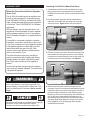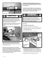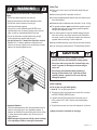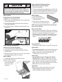
1
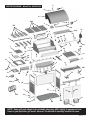
463247504 • 80002112 • 03-24-04
WARNING
FOR YOUR SAFETY
1. Do not store or use gasoline or other
flammable vapors and liquids in the
vicinity of this or any other appliance.
2. An LP tank not connected for use shall
not be stored in the vicinity of this or any
other appliance.
FOR YOUR SAFETY
If you smell gas:
1. Shut off gas to the appliance.
2. Extinguish any open flame.
3. Open lid.
4. If odor continues, immediately call your
gas supplier or your fire department.
Call Grill Service Center For Help And Parts
• If you need help or warranty parts call 1-800-241-7548 U.S. or
1-800-387-6057 CANADA.
Business hours: Open 24 hours – Seven days a week.
• To order non-warranty replacement parts or accessories (grill
cover, cleaners, paint) call 1-800-993-2677 or send a FAX to
1-706-565-2121.
IMPORTANT: Fill out the product record information below.
Model Number
Installation Safety Precautions
• This grill is designed for natural gas use at 7 inch water column
supply pressure. Verify supply pressure with your local gas
company. If supply pressure is different than 7 inch, contact a
certified plumber for assistance. Not for use with LP gas.
• Grill installation must conform with local codes, or in their
absence with National Fuel Gas Code, NFPA 54 / ANSI
Z223.1 or CAN/CGA-B149.2 Propane Installation Code.
Handling and storage of LP cylinders must conform to LP Gas
Code NFPA/ANSI 58. Grill is not for use in or on recreational
vehicles and/or boats.
• All electrical accessories (such as rotisserie) must be
electrically grounded in accordance with local codes, or
National Electrical Code, ANSI / NFPA 70 or Canadian
Electrical Code, CSA C22.1. Keep any electrical cords and/or
fuel supply hoses away from any hot surfaces.
• This grill is safety certified for use in the United States or
Canada only. Do not modify for use in any other location.
Modification will result in a safety hazard.
Safety Symbols
The symbols and boxes shown below explain what each heading
means. Read and follow all of the messages found throughout
the manual.
DANGER
DANGER: Indicates an imminently hazardous situation
which, if not avoided, will result in death or serious injury.
WARNING
Serial Number
See new rating label provided for serial number.
WARNING: Indicates a potentially hazardous situation which,
if not avoided, could result in death or serious injury.
Date Purchased
CAUTION
CAUTION
For residential use only. Do not use for commercial
cooking.
WARNING
CALIFORNIA PROPOSITION 65
Combustion by-products produced when using this
product contain chemicals known to the State of
California to cause cancer, birth defects, and other
reproductive harm.
2 • 463247504
CAUTION: Indicates a potentially hazardous situation or
unsafe practice which, if not avoided, may result in minor or
moderate injury.
TABLE OF CONTENTS
For Your Safety . . . . . . . . . . . . . . . . . . . . . . . . . . . . . . . . . . . . . . 2
Grill Service Center. . . . . . . . . . . . . . . . . . . . . . . . . . . . . . . . . . . 2
Product Record Information . . . . . . . . . . . . . . . . . . . . . . . . . . . . 2
Installation Safety Precautions . . . . . . . . . . . . . . . . . . . . . . . . . . 2
Safety Symbols. . . . . . . . . . . . . . . . . . . . . . . . . . . . . . . . . . . . . . 2
Warranty . . . . . . . . . . . . . . . . . . . . . . . . . . . . . . . . . . . . . . . . . . . 3
Parts List. . . . . . . . . . . . . . . . . . . . . . . . . . . . . . . . . . . . . . . . . . . 4
Parts Diagram. . . . . . . . . . . . . . . . . . . . . . . . . . . . . . . . . . . . . . . 5
Assembly . . . . . . . . . . . . . . . . . . . . . . . . . . . . . . . . . . . . . . . . 6-12
Use and Care . . . . . . . . . . . . . . . . . . . . . . . . . . . . . . . . . . . 13-21
WARRANTY
Manufacturer warrants to the original consumerpurchaser that this product shall be free from defects in
workmanship and materials under normal and reasonable
use and correct assembly (if assembled by consumerpurchaser), from date of purchase.
Stainless steel and die cast parts - 99 years
Electronic ignition (excluding battery) and
cast iron burners - 10 years
Remaining parts (excluding battery) - 2 years
Manufacturer will, at its option, refinish or replace any
product or part found to be defective during the warranty
period. Manufacturer will require you to return the part(s)
claimed to be defective, for its inspection, freight or postage
prepaid.
If you wish to obtain performance of any obligation under
this limited warranty, you should write to:
Consumer Warranty / P.O. Box 1240
Columbus, GA 31902-1240
Stainless Steel Use and Care
Stainless steel grills can provide many years of reliable
service and an attractive appearance in normal outdoor
exposure. Consider the following tips to extend the
appearance of your stainless steel grill:
• Cooking smoke from normal use of the grill will eventually
coat and discolor the stainless steel surface. Periodic
cleaning of the surface with readily available stainless
steel cleaners is recommended. (In coastal areas, small
rust pits may develop on the surface of your grill that
cannot be fully removed by a cleaner.)
• Periodic cleaning of the cooking grates also helps
decrease the risk of a grease fire which can irreversibly
darken the stainless steel surface. (Please note that the
integrity of the steel is not affected by the flame, only the
appearance.)
Manufacturer may require reasonable proof of purchase
and we suggest you keep your receipt. In the state of
California only, if refinishing or replacement of the product is
not commercially practicable, the retailer selling this product
or Manufacturer will refund the purchase price paid for the
product, less the amount directly attributable to use by the
original consumer-purchaser prior to discovery of the
nonconformity. In addition, in the state of California only, you
may take the product to the retail establishment from which it
was purchased or to any retail establishment selling this
product in order to obtain performance under this warranty.
This warranty does not include the cost on any
inconvenience or property damage due to failure of the
product and does not cover damage due to misuse, abuse,
accident, damage arising out of transportation of the product,
or damage incurred through commercial use of the product.
This express warranty is the sole warranty given by the
manufacturer and is in lieu of all other warranties, express or
implied, including implied warranty of merchantability or
fitness for a particular purpose. Neither Manufacturer dealers
nor the retail establishment selling this product has any
authority to make any warranties or to promise remedies in
addition to or inconsistent with those stated above.
Manufacturer's maximum liability, in any event, shall not
exceed the purchase price of the product paid by the original
consumer-purchaser. Some states do not allow the exclusion
or limitation of incidental or consequential damages. So the
above limitations or exclusions may not apply to you. This
warranty gives you specific legal rights and may also have
other rights which vary from state to state.
463247504 • 3
PARTS LIST – Model No. 463247504
Key Qty
Description
Part #
1
Grill Lid Assembly . . . . . . . . . . . . . . . 80000836
A
1
Lid. . . . . . . . . . . . . . . . . . . . . . . . . . . . . 80000837
B
1
C
Key Qty
Description
Part #
1
Cart Assembly . . . . . . . . . . . . . . . . . . 80001649
GG
1
Leg Assembly with Panel, Left . . . . . . . 80001904
Lid Handle . . . . . . . . . . . . . . . . . . . . . . 80000842
HH
1
Leg Assembly with Panel, Right. . . . . . 80001573
1
Handle Seat, Left . . . . . . . . . . . . . . . . . 80000845
II
1
Cart Back Panel . . . . . . . . . . . . . . . . . . 80001577
D
1
Handle Seat Plate, Left . . . . . . . . . . . . 80000511
JJ
4
Caster Socket. . . . . . . . . . . . . . . . . . . . 80000377
E
1
Handle Seat, Right . . . . . . . . . . . . . . . . 80000846
KK
1
Bottom Shelf. . . . . . . . . . . . . . . . . . . . . 80001579
F
1
Handle Seat Plate, Right . . . . . . . . . . . 80000512
G
1
Thermometer . . . . . . . . . . . . . . . . . . . . 80000096
1
Rotisserie Motor and Spit Assembly 80001603
H
1
Thermometer Bezel . . . . . . . . . . . . . . . 80000097
LL
1
Spit Rod . . . . . . . . . . . . . . . . . . . . . . . . 80001604
I
1
Logo Plate . . . . . . . . . . . . . . . . . . . . . . 80001402
MM
1
Spit Handle. . . . . . . . . . . . . . . . . . . . . . 80001328
NN
1
Collar . . . . . . . . . . . . . . . . . . . . . . . . . . 80001329
1
Grill Bottom Assembly. . . . . . . . . . . . 80001646
OO
2
Fork . . . . . . . . . . . . . . . . . . . . . . . . . . . 80001330
J
1
Grill Bottom . . . . . . . . . . . . . . . . . . . . . 80001517
PP
1
Rotisserie Motor . . . . . . . . . . . . . . . . . . 80001627
K
4
Main Burner . . . . . . . . . . . . . . . . . . . . . 80001254
QQ
1
Rotisserie Mounting Bracket, Right . . . 80001422
L
1
Burner Brace/Carryover . . . . . . . . . . . . 80001535
RR
1
Rotisserie Mounting Bracket, Left . . . . 80001333
M
1
Manifold Heat Shield . . . . . . . . . . . . . . 80001539
N
1
Ignitor System Assembly . . . . . . . . . . . 80001615
SS
1
Door Assembly - Left . . . . . . . . . . . . . . 80001583
O
1
Control Panel . . . . . . . . . . . . . . . . . . . . 80001903
TT
1
Door Assembly - Right . . . . . . . . . . . . . 80001586
P
6
Control Knob . . . . . . . . . . . . . . . . . . . . 80000825
UU
1
Door Brace . . . . . . . . . . . . . . . . . . . . . . 80001607
Q
5
Control Knob Bezel . . . . . . . . . . . . . . . 80001930
VV
2
Condiment Basket . . . . . . . . . . . . . . . . 80001619
R
1
Smoker Tray. . . . . . . . . . . . . . . . . . . . . 80001542
WW
2
Locking Caster . . . . . . . . . . . . . . . . . . . 80000268
S
1
Manifold/Hose/Regulator Assembly . . . 80001647
XX
2
Fixed Caster. . . . . . . . . . . . . . . . . . . . . 80000269
T
1
Rotisserie Burner Assembly . . . . . . . . . 80000871
YY
1
Grease Tray . . . . . . . . . . . . . . . . . . . . . 80001589
U
1
Rotisserie Electrode . . . . . . . . . . . . . . . 80000885
ZZ
1
Grease Receptacle. . . . . . . . . . . . . . . . 80001622
V
4
Rotisserie Hose Clip. . . . . . . . . . . . . . . 80001550
AAA
1
SwingAway Warming Rack . . . . . . . . . 80001624
W
2
Rotisserie Wind Shield . . . . . . . . . . . . . 80001639
BBB
1
Cooking Grate Set . . . . . . . . . . . . . . . . 80001643
CCC 1
Sideburner Grate . . . . . . . . . . . . . . . . . 80000282
1
Sideburner Shelf Assembly. . . . . . . . 80001551
DDD 2
Match-Lighting Stick. . . . . . . . . . . . . . . 80001923
X
1
Sideburner Frame . . . . . . . . . . . . . . . . 80001553
EEE
4
Flametamers . . . . . . . . . . . . . . . . . . . . 80000947
Y
1
Sideburner Lid . . . . . . . . . . . . . . . . . . . 80000539
FFF
1
Sideburner Valve Clip. . . . . . . . . . . . . . 80000455
Z
1
Sideburner Pan . . . . . . . . . . . . . . . . . . 80000051
GGG 1
AA Battery . . . . . . . . . . . . . . . . . . . . . . 80000284
AA
1
Sideburner Electrode . . . . . . . . . . . . . . 80000055
HHH 1
12’ Natural Gas Hose (w/small socket). . 80001456
BB
1
Sideburner Control Panel. . . . . . . . . . . 80001556
CC
2
Towel Bar . . . . . . . . . . . . . . . . . . . . . . . 80001558
III
1
Regulator Bracket. . . . . . . . . . . . . . . . . 80001625
DD
1
Sideburner Assembly . . . . . . . . . . . . . . 80001035
JJJ
2
Door Handle . . . . . . . . . . . . . . . . . . . . . 80000086
KKK
4
Tool Hook . . . . . . . . . . . . . . . . . . . . . . . 80001642
12’ Natural Gas Hose (w/large socket) . . 80001928
1
Side Shelf Assembly . . . . . . . . . . . . . 80001559
1
Hardware Pack. . . . . . . . . . . . . . . . . . . 80001650
EE
1
Side Shelf. . . . . . . . . . . . . . . . . . . . . . . 80001560
1
Product Guide . . . . . . . . . . . . . . . . . . . 80001643
FF
1
Side Shelf Panel. . . . . . . . . . . . . . . . . . 80001260
4 • 463247504
H
PARTS DIAGRAM – Model No. 463247504
I
G
A
E
BBB
C
F
D
EEE
B
AAA
W
T
U
OO
V
OO
W
L
MM NN
V
K
RR
Y
K
J
K
PP
QQ
LL
KKK
EE
M
V
DD
CCC
AA
DD
X
CC
CC
R
V
FF
S
FFF
YY
O
Q
P
KKK
III
P
II
Z
BB
DDD
GGG
N
ZZ
P
DD
UU
TT
DDD
GG
JJ
JJ
HHH
SS
HH
JJ
XX
JJJ
JJJ
XX
VV
JJ
WW
WW
KK
VV
NOTE: Some grill parts shown in the assembly steps may differ slightly in appearance from
those on your particular grill model. However, the method of assembly remains the same.
463247504 • 5
ASSEMBLY – Model No. 463247504
1
Place sideburner shelf over left cart legs. Lip of shelf should fit between grill bottom and leg brace. (It may be necessary to
slightly loosen the two screws from inside the grill bottom, and tighten them again once shelf is attached.) Secure shelf
brackets to cart legs using two 1/4-20x1/2” screws (LLL), 7mm lock washers (MMM), and 7mm flat washers (NNN) on
each bracket. Repeat procedure to install side shelf on right side of grill.
CAUTION
Loosen
these screws
if necessary.
SHARP EDGES! Wear gloves if necessary.
Repeat on front bracket
LLL
MMM
NNN
2
Sideburner
shelf
Repeat procedure to
install side shelf on
right side of grill.
Remove the two screws (M4x10mm) and washers (4mm) from the sideburner valve bracket.
Place sideburner valve under front of sideburner control panel so that valve stem comes through
large hole. Secure valve bracket to panel using the two screws and washers you removed
previously. Press control knob onto valve stem. Using a small slotted screwdriver, tighten the
control knob set screw through the hole at the bottom edge of the knob.
Control
Knob
Valve stem
First, remove
screws and
washers from
bracket.
Set screw hole
6 • 463247504
Sideburner
valve
3
Insert sideburner into shelf, placing end of burner over sideburner
valve. Valve should be in center hole of burner tube. See
illustration below for correct burner-to-valve engagement. Make
sure pin on bottom of burner is in center hole in shelf bracket.
Insert short-threaded ends of double-sided screws (OOO)
through holes in bracket and into burner. Wrench-tighten. Attach
ignitor wire to sideburner electrode. Align cup cut-out with
sideburner tube and holes in cup bottom with double-sided
screws. Place ignitor wire through burner tube cutout in cup.
Secure with 5mm flat washers (PPP), 5mm lock washers
(QQQ) and #10-24 hex nuts (RRR).
Short
Correct
burner-to-valve
engagement
threads
OOO
Sideburner
Long
threads
Ignitor
Wire
PPP
QQQ
Valve should be in center
hole in burner tube.
4
RRR
Insert valve clip into small hole in bottom of burner, then snap other end of clip over sideburner valve. Place brass top on
sideburner, then place sideburner grate onto shelf.
Valve clip
463247504 • 7
5
Remove screws and washers from ends of towel bars. Slide tool hooks onto towel bars as desired. Insert screws from
beneath shelf, through shelf holes and into ends of towel bar. Repeat procedure on sideburner shelf. Remove screws
and washers from both the rotisserie motor bracket and the spit rod bracket. Attach the rotisserie motor bracket to the right
side of the grill bottom using two #10-24x3/8” screws (SSS), 5mm lock washers (QQQ), and 5mm flat washers (PPP) from
the outside and two #10-24 hex nuts (RRR) on the inside of the grill bottom. Attach the spit rod bracket to the left side of
the grill bottom in the same manner.
DO NOT USE TOWEL
BARS TO LIFT GRILL.
RRR
Rotisserie motor bracket
Spit rod bracket
(Left side of grill bottom)
Rotisserie motor bracket
(Right side of grill bottom)
Towel bar
PPP QQQ SSS
Lock
washer
Flat
washer
Tool hook
Towel Bar Hardware
6
Place flametamers (4) over burners by inserting tabs into slots in front of firebox. Opposite ends of flametamers rest on pins
in back of firebox.
Fro
nt o
NOTE: SwingAway
not shown for clarity.
er
f fir
x
Fl
am
et
am
rebo
fi
k of
Bac
Fla
me
8 • 463247504
tam
er
ebo
x
7
Place cooking grates into grill bottom.
NOTE: SwingAway
not shown for clarity.
8
Open cart doors to attach condiment baskets. Slide basket wires into brackets on doors.
Cart door
Condiment basket
463247504 • 9
9
Hang the match-lighting sticks and chains from the small
hooks on the right and left side panels.
10
Unscrew ignitor cap and place AA
battery into ignitor slot with positive end
(+) facing outward. Screw ignitor cap
onto ignitor.
+
–
AA Battery
10 • 463247504
11
Twist the handle stopper fully onto threaded end of spit rod, then twist handle onto rod. Next, slide the collar onto the rod
followed by the two forks (forks should be pointing toward each other). Insert thumbscrews into collar and forks.
Handle
stopper
Thumbscrews
Handle
12
Collar
Thumbscrew
Fork
Spit rod
Fork
On right side of grill, slide rotisserie motor onto motor bracket. Switch should be oriented at rear of motor. Insert spit rod fully
into motor. On left side of grill, adjust position of collar to rest in bracket, then tighten collar thumbscrew.
NOTE: SwingAway must be removed when using rotisserie.
Left side of grill
Right side of grill
Rotisserie
motor
Spit
rod
Collar
Bracket
Motor
bracket
463247504 • 11
13
Beneath sideburner shelf, attach regulator bracket to regulator using two ST4.2x10mm, self-tapping screws (TTT) and two
5mm flat washers (PPP). Make sure taller side of bracket, with hole at top, faces front of grill. Remove screw, flat washer,
lock washer and hex nut at end of shelf bracket (near towel bar). Remove screw and lock washer at bottom front of
sideburner and brass hex nut at top of sideburner. Align hole in regulator bracket with hole at end of shelf bracket. Insert
screw through brackets and reinstall flat washer, lock washer and hex nut. Reinstall screw, lock washer and brass hex nut.
Regulator
Regulator
bracket
PPP
TTT
14
Beneath sideburner control shelf, thread the natural gas hose onto the regulator fitting and wrench-tighten the connection.
NOTE: The natural gas hose comes
with a 3/8” internal-threaded
fitting at the end; remove
and discard it.
See Use & Care section
for important safety instructions.
Please read “Connecting Your
Natural
Grill to the Natural Gas
Gas Hose
Source”, “Leak Test”, and
“Burner Flame Check”
before using grill.
12 • 463247504
USE AND CARE
Natural Gas Connections and Service Regulators
Above 1/2 psi.
Prior to 1998, all residual gas service regulators were
set with an outlet pressure of 7 inches water column.
In the 1998 edition of NFPA 54, the National Fuel Gas
Code, a change was made allowing service regulators
of 2 and 5 psi. Check CAN/CSA B149.1 for Canadian
requirement.
With this change it was also required that an in line
regulator be connected between the service regulator
and the appliance regulator if the 2 or 5 psi system is
used. This additional regulator is not supplied with the
product.
It is possible for a consumer, making the connection
themselves, or a plumber, not checking, to tap into a 2
or 5 psi line. If a pressure of 2 psi or greater is supplied
to the appliance regulator on certain grills it will shut
down and not deliver any gas to the grill. Other
concerns are the quick disconnect socket and hose
which are only rated to 1/2 psi.
If the quick disconnect socket, hose, and grill are
properly connected and still not getting gas, delivery
pressure needs to be verified. If pressure is greater
than 1/2 psi, make sure that an in line regulator is
present.
Once the grill has been over-pressured, the regulator
may or may not have been damaged. The best practice
is to replace the regulator.
Connecting Your Grill to the Natural Gas Source
1. A professionally-installed shut-off valve between the supply
piping and the socket is recommended, but not required, by
the National Fuel Gas Code. Socket connection must be made
outdoors.
2. Coat the gas supply pipe nipple with gas resistant dope or
teflon tape. Screw socket onto gas supply pipe (house gas
source) as shown in Figure A below, and wrench-tighten.
Quick disconnect socket
House piping
Figure A
3. Pull back the sleeve on the quick disconnect socket and insert
the unattached end of the gas hose into the socket. Release
the sleeve and continue pushing the hose into the socket until
the sleeve snaps into the locked position. See Figure B.
Gas hose
Sleeve
WARNING
This grill is designed for natural gas use at 7 inch water
column supply pressure. Verify supply pressure with your
local gas company. If supply pressure is different than 7 inch,
contact a certified plumber for assistance. Not for use with
LP gas.
DANGER
Connection should be made by a certified plumber. Supply the
plumber with a copy of these instructions. Incorrect
connection can result in a gas leak with possibility of fire.
Figure B
4. When the quick disconnect socket and the gas hose are
connected, a valve in the socket opens automatically to permit
full gas flow. When the gas hose is disconnected, the valve in
the socket instantly and positively shuts off the flow of gas.
Because the valve in the socket positively shuts off the flow of
gas, the grill can be disconnected from the gas source by
disconnecting the gas hose from the quick disconnect socket.
The socket should be left attached to the gas source (house
piping). Figure C, on the following page, shows properly
connected hose and socket.
463247504 • 13
The appliance and its individual shut off valve must be
disconnected from the gas supply piping system during any
pressure testing on that system at test pressures in excess
of 1/2 psig (3.5kPa).
The appliance must be isolated from the gas supply piping
system by closing its individual manual shutoff valve during
any pressure testing of the gas supply piping system at test
pressures equal to or less than 1/2 psi (3.5kPa).
Figure C
WARNING
CAUTION
If a coupling is supplied with your gas hose, do not
attach the coupling to the quick disconnect socket for
connection to your house piping. Use of the coupling
will alter the gas flow, which may be a safety concern
under some circumstances. See Figure D.
The quick disconnect socket should never be connected
to the grill. Direction of gas flow is indicated on the
socket.
Do not use hard metal piping of any kind to connect this
type of grill to natural gas source. Use only hose
specified by manufacturer. Using hard metal piping or
convoluted metal tubing is an unsafe practice. Movement
of the grill can cause breakage of metal pipe.
Leak Testing
1. Turn all grill control knobs to OFF.
2. Be sure gas hose is tightly connected to gas source.
3. Completely open gas source. If you hear a rushing sound, turn
gas off immediately. There is a major leak at the connection.
Correct before proceeding.
4. Brush soapy solution onto areas circled below.
Figure D
With proper assembly, the gas hose cannot be removed
without pushing the quick disconnect sleeve back. To
disconnect, push sleeve back and pull plug out of sleeve (this
automatically shuts off gas).
Please Note: Hose and assembly are C.S.A. listed for
natural gas, manufactured gas, mixed gas and for liquefied
petroleum and for LP Gas-Air mixtures on basis of 0.64
specific gravity for 1000 BTU’s per cubic foot of gas at 0.3
in. water column pressure drop. Only ANSI Z21.54 approved
hoses should be used with this grill.
NOTE: Some parts
not shown for
clarity.
5. If “growing” bubbles appear, there is a leak. Close gas
source immediately and retighten connection. If leaks cannot
be stopped do not try to repair. Call for replacement parts.
Order new parts by giving the serial, model number and name
of items needed to the Grill Service Center at 1-800-241-7548.
6. Always close gas source after performing leak test.
14 • 463247504
WARNING
For Safe Use Of Your Grill And To Avoid Serious
Injury:
Do not let children operate or play near grill.
Keep grill area clear and free from materials that burn.
Do not block holes in bottom or back of grill.
Check burner flames regularly.
Use grill only in well-ventilated space. NEVER use in
enclosed space such as carport, garage, porch, covered
patio, or under an overhead structure of any kind.
• Do not use charcoal or ceramic briquets in a gas grill.
(Unless briquets are supplied with your grill.)
• Use grill at least 3 ft. (1 meter) from any wall or surface.
Maintain 10 ft. (3 meters) clearance to objects that can
catch fire or sources of ignition such as pilot lights on water
heaters, live electrical appliances, etc..
•
•
•
•
•
Safety Tips
s When grill is not in use, turn off all control knobs and gas
source.
s Never move grill while in operation or still hot.
s Use long-handled barbecue utensils and oven mitts to avoid
burns and splatters.
s Maximum load for sideburner and side shelf is 10 lbs. (4.5kg).
s The grease receptacle must be attached to grease tray and
emptied after each use. Do not remove grease receptacle
until grill has completely cooled.
s If you notice grease or other hot material dripping from grill
onto valve or hose, turn off gas source at once. Determine
the cause, correct it, then clean and inspect valve, hose and
regulator before continuing. Perform a leak test.
s Keep ventilation openings in grill cart free and clear of debris.
s If you have a grill problem see the "Troubleshooting Section".
CAUTION
• Putting out grease fires by closing the lid is not
possible. Grills are well ventilated for safety reasons.
• Do not use water on a grease fire. Personal injury may
result. If a grease fire develops, turn knobs and gas
source off.
• Do not leave grill unattended while preheating or
burning off food residue on HI. If grill has not been
regularly cleaned, a grease fire can occur that may
damage the product.
Ignitor Lighting
s Do not lean over grill while lighting.
1. Open lid. Turn on gas at gas source.
2. To ignite, turn left or right center burner knob to HI, push and
hold ELECTRONIC IGNITOR button.
3. If ignition does NOT take place within 5 seconds, turn all
burner valves to OFF, wait 5 minutes, then repeat lighting
procedure.
• Apartment Dwellers:
Check with management to learn the requirements and fire
codes for using a gas grill in your apartment complex. If
allowed, use outside on the ground floor with a three (3) foot
(1 meter) clearance from walls or rails. Do not use on or
under balconies.
• NEVER attempt to light burner with lid closed. A buildup
of non-ignited gas inside a closed grill is hazardous.
4. To ignite other burners, turn knob to HI adjacent to a lit burner
.
Lighting instructions continued on next page.
463247504 • 15
CAUTION
If burner does not light, turn knobs to OFF , wait 5
minutes, and try again. If the burner does not ignite with
the valve open, gas will continue to flow out of the burner
and could accidently ignite with risk of injury.
Ignitor Lighting The Rotisserie Burner
s Do not lean over grill while lighting.
1. Open lid during lighting.
2. To ignite rotisserie burner, turn rotisserie burner knob to ON,
push and hold ELECTRONIC IGNITOR button for 5 seconds.
3. If rotisserie burner does NOT light, turn knob to OFF, wait 5
minutes, then repeat lighting procedure or use match.
Match-Lighting
Match Lighting
s Do not lean over grill while lighting.
1. Open lid. Turn on gas at gas source.
2. Place lit match into match lighting stick, then into lighting hole
on left or right side of grill.
3. Push in and turn far left or right burner knob to HI. Be sure
burner lights and stays lit.
4. Light adjacent burners in sequence by pushing knobs in and
turning to HI.
1. Open lid during lighting.
2. Place lit match near rotisserie
spark electrode wire.
3. Push in and turn rotisserie burner knob
to ON. Be sure burner lights and stays lit.
NOTE: Do not operate the rotisserie burner and the main
burners at the same time.
Burner Flame Check
• Remove grates and flametamers. Light burner, rotate knobs
from HI to LOW. You should see a smaller flame in LO position
than seen on HI. Always check flame prior to each use.
Perform flame check on sideburner. If only low flame is seen
refer to "Sudden drop or low flame" in the Troubleshooting
Section.
HI
LO
Turning Grill Off
Ignitor Lighting The Sideburner
s Do not lean over grill while lighting.
1. To ignite sideburner, open sideburner cover.
2. Turn sideburner knob to HI, push and hold ELECTRONIC
IGNITOR button.
3. If sideburner does NOT light, turn knob to OFF, wait 5 minutes,
then repeat lighting procedure or use match.
Match Lighting
1. To match light sideburner, open sideburner cover.
2. Place lit match near burner.
3. Push in and turn sideburner
knob counterclockwise.
Be sure burner lights
and stays lit.
• Turn all knobs to OFF position. Turn gas OFF at gas source.
Ignitor Check
• Turn gas off at gas source. Press and hold electronic ignitor
button. "Click" should be heard and spark seen each time
between collector box or burner and electrodes. See
"Troubleshooting" if no click or spark.
Valve Check
• Important: Make sure gas is off at gas source before
checking valves. Knobs lock in OFF position. To check
valves, first push in knobs and release, knobs should spring
back. If knobs do not spring back, replace valve assembly
before using grill. Turn knobs to LO position then turn back to
OFF position. Valves should turn smoothly.
Hose Check
• Before each use, check to see if hoses are cut or worn.
Replace damaged hoses before using grill. Use only
valve/hose/regulator specified by manufacturer.
16 • 463247504
General Grill Cleaning
• Do not mistake brown or black accumulation of grease and
smoke for paint. Interiors of gas grills are not painted at the
factory (and should never be painted). Apply a strong solution
of detergent and water or use a grill cleaner with scrub brush
on insides of grill lid and bottom. Rinse and allow to completely
air dry. Do not apply a caustic grill/oven cleaner to painted
surfaces.
• Plastic parts: Wash with warm soapy water and wipe dry.
s Do not use citrisol, abrasive cleaners, degreasers or a
concentrated grill cleaner on plastic parts. Damage to and
failure of parts can result.
• Porcelain surfaces: Because of glass-like composition, most
residue can be wiped away with baking soda/water solution or
specially formulated cleaner. Use nonabrasive scouring powder
for stubborn stains.
• Painted surfaces: Wash with mild detergent or nonabrasive
cleaner and warm soapy water. Wipe dry with a soft
nonabrasive cloth.
• Stainless steel surfaces: To maintain your grill’s high quality
appearance, wash with mild detergent and warm soapy water
and wipe dry with a soft cloth after each use. Baked-on grease
deposits may require the use of an abrasive plastic cleaning
pad.
CAUTION
NATURAL HAZARD • SPIDERS
FACT: Sometimes spiders and other small insects climb into
the burner tubes attached to the burners. The spiders spin
webs, build nests and lay eggs. The webs or nests
can be very small, but they are very strong
and can block the flow of gas. Clean
burners prior to use after storing, at the
beginning of grilling season or after a period
of one month not being used.
Spider guards are on the air intakes in an effort to reduce this
problem, but it will not eliminate it! An obstruction can result
in a "flashback" (a fire in the burner tubes). The grill may still
light, but the obstruction does not allow full gas flow to the
burners.
IF YOU EXPERIENCE THE FOLLOWING:
1. Smell gas.
2. Burner(s) will not light.
3. A small yellow flame from burner (should be blue).
4. Fire coming from around or behind control knob.
Storing Your Grill
STOP!
• Clean cooking grates.
• Store in dry location.
• Cover grill if stored outdoors. Choose from a variety of grill
covers offered by manufacturer.
• Store grill indoors ONLY if gas source is turned off and
disconnected, removed from grill and stored outdoors.
• When removing grill from storage, follow “Cleaning the Burner
Assembly” instructions before starting grill.
Immediately turn off gas at LP tank!
SOLUTION:
Wait for grill to cool.
Follow the “Cleaning The Burner Assembly” instructions.
Clean burners often. Use a 12” pipe cleaner to clean out the
burner tubes. You may also force a stream of water from a
hose nozzle through burner tubes to clean them.
Grease Tray and Receptacle
MAKE SURE GRILL IS COOL. To empty the grease receptacle, grasp
the handle and slide it out of grease tray. To remove grease tray for
cleaning, lift it from the back and slide entire tray out of cart.
Grease
tray
Grease
receptacle
CAUTION
• Failure to install receptacle on tray will cause hot
grease to drip from bottom of grill with risk of fire or
property damage.
463247504 • 17
Cleaning The Burner Assembly
Follow these instructions to clean and/or replace parts of burner
assembly or if you have trouble igniting grill.
1. Turn gas off at control knobs and gas source.
2. Remove cooking grates, flametamers, grease tray and
grease receptacle.
3. Remove cotter pins from beneath each burner "foot" using a
screwdriver or needle nose pliers.
4. Carefully lift each burner up and away from valve openings.
We suggest three ways to clean the burner tubes. Use the one
easiest for you.
(A) Bend a stiff wire (a light weight coat hanger works well)
into a small hook. Run the hook through each burner
tube and burner several times.
(B) Use a narrow bottle brush with a flexible handle (do not
use a brass wire brush), run the brush through each
burner tube and burner several times.
(C) Wear eye protection: Use an air hose to force air into
the burner tube and out the burner ports. Check each
port to make sure air comes out each hole.
5. Wire brush entire outer surface of burner to remove food
residue and dirt.
6. Clean any blocked ports with a stiff wire such as an open
paper clip.
7. Check burner for damage, due to normal wear and corrosion
some holes may become enlarged. If any large cracks or
holes are found replace burner.
VERY IMPORTANT: Burner tubes must reengage valve
openings. See illustrations below.
8. Carefully replace burners.
9. Replace cotter pin beneath each burner.
10. Replace grease tray, grease receptacle, flametamers and
cooking grates.
18 • 463247504
Valve
Burner
Indirect Cooking
Using the Smoker Tray
Poultry and large cuts of meat cook slowly to perfection on
the grill by indirect heat. The heat from selected burners
circulates gently throughout the grill, cooking meat or poultry
without the touch of a direct flame. This method greatly reduces
flare-ups when cooking extra fatty cuts because there is no direct
flame to ignite the fats and juices that drip during cooking.
1. While the grill is cool, remove the right cooking grate.
2. Add enough wood chips to completely fill the smoker tray.
3. Light the center main burner first, then the right burner, then
turn the center burner off.
4. Place food on the left cooking grate. Wood chips should begin
smoking within 15 minutes.
Make sure grill has completely cooled before emptying
smoker tray. To empty the smoker tray, pull the tray completely
out of the grill bottom through the control panel.
Indirect Cooking Instructions
• Always cook with the lid closed.
• Due to weather conditions, cooking times may vary. During
cold and windy conditions the temperature setting may need
to be increased to insure sufficient cooking temperatures.
Smoker
tray
ON
1 Burner Cooking
Cook with direct or indirect heat.
Best for smaller meals or foods.
Consumes less fuel.
How To Tell If Meat Is Grilled Thoroughly
ON
ON
• Meat and poultry cooked on a grill often browns very fast on the
outside. Use a meat thermometer to be sure food has reached
a safe internal temperature, and cut into food to check for
visual signs of doneness.
• Whole poultry should reach 180° F; breasts, 170° F. Juices
should run clear and flesh should not be pink.
• Hamburgers made of any ground meat or poultry should reach
160° F, and be brown in the middle with no pink juices. Beef,
veal and lamb steaks, roasts and chops can be cooked to 145°
F. All cuts of pork should reach 160° F.
• NEVER partially grill meat or poultry and finish cooking later.
Cook food completely to destroy harmful bacteria.
• When reheating takeout foods or fully cooked meats like hot
dogs, grill to 165° F, or until steaming hot.
2 Burner Cooking
Great indirect cooking on low.
Produces slow, even heating.
Ideal for slow roasting and baking.
463247504 • 19
Troubleshooting
Problem
Possible Cause
Prevention/Solution
Burner(s) will not light
using ignitor.
• Wire and/or electrode covered with
cooking residue.
• Electrode cracked or broken "sparks at
crack”.
• Electrode tip not in proper position.
• Clean wire and/or electrode with rubbing alcohol and clean swab.
• Replace electrode(s).
• Main Burners: Tip of electrode should be pointing toward tip of
collector box. The distance should be 1/8” to 1/4”, adjust if
necessary.
• Sideburner: Tip of electrode should be pointing toward gas port
opening on burner. The distance should be 1/8” to 3/16”, adjust if
necessary.
• Wires are loose or disconnected.
• Wires are shorting (sparking) between
ignitor and electrode.
• Dead battery.
No gas flow.
Obstruction of gas flow.
Disengagement of burner to valve.
Is grill assembled correctly?
• Reconnect wires or replace electrode/wire assembly.
• Replace ignitor wire/electrode assembly.
• Replace with a new AA battery.
Burner(s) will not
match light.
•
•
•
•
Flames blow out.
• High or gusting winds.
• Turn front of grill to face wind or increase flame height.
Flare-up.
• Grease buildup.
• Excessive fat in meat.
• Excessive cooking temperature.
• Clean grill.
• Trim fat from meat before grilling.
• Adjust (lower) temperature accordingly.
Persistent grease fire.
• Grease trapped by food buildup around
burner system.
• Turn knobs to OFF. Turn gas off at gas source. Leave lid in position
and let fire burn out. After grill cools, remove and clean all parts.
Flashback...
(fire in burner tube(s)).
• Burner and/or burner tubes are blocked.
• Turn knobs to OFF. Clean burner and/or burner tubes.
•
•
•
•
Turn gas on at gas source.
Clear burner tube(s).
Reengage burner and valve.
Check steps in assembly instructions.
Certified Grill Parts And Accessories®, Char-Broil and Design®, Char-Broil (Gas Grill Briquettes)®, Char-Diamonds®, Cooking Zone and Design®, Diamond Flame®, Executive Chef®, Faststart®, Flare
Fighter®, FlavorMaster®, Gas Grill Silouette and Design®, H2O Smoker®, Lava Flame®, MasterFlame®, MasterFlame Precision Cooking System®, PowerSpark®, Quantum®, VIP®, PrecisionFlame and
Design®, Sierra®, and TruFlame® are registered Trademarks of the W.C. Bradley Company. Thermos® is a registered trademark of the Thermos Company and its affiliates.
Artisan Collection by Char-Broil ™, C3 and Design™, Char-Broil and Design™, Flame Design™, FlavorTents™, Grill 2 Go™, Grillin’ Stick™, Keeper of the Flame™, Keepers of the Flame™, Natural Grip™,
Outdoor Cooking Collection and Design™, Patio Bistro™, PrecisionFlame™, Pro-Check™, QuickSet Grills and Design™, SmokerTents™, The Big Easy™, The Minute Grill™, The Edge™, The Tuscan
Collection™, and The Urban Grill™ are Trademarks of the W.C. Bradley Company. Universal Grill Parts and Design™ is a trademark of the Thermos Company and its affiliates.
Protected under one or more of the following U.S. Patents: 4,598,692; 4,624,240; 4,747,391; 4,747,391; 4,817,583; 4,924,846; 4,989,579; 5,003,960; 5,076,256; 5,076,257; 5,090,398; 5,109,834; 5,224,676;
5,277,106; 5,421,319; 5,441,226; 5,452,707; 5,458,309; 5,566,606; 5,566,606; 5,579,755; 5,582,094; 5,613,486; 5,649,475; 5,706,797; 5,711,663; 5,765,543; 5,931,149; 5,996,573; 6,095,132; 6,135,104;
6,173,644B1; 6,279,566; 6,397,731; 6,418,923; 6,439,222; 6,523,461; D282,619; D339,714; D341,292; D343,337; D358,059; D361,466; D364,535; D372,637; D373,701; D377,735; D383,035; D397,910;
D405,643; D405,643; D406,005; D406,009; D413,043; D413,229; D413,229; D414,982; D415,388; D416,164; D416,441; D416,441; D417,587; D422,516; D423,274; D423,876; D428,303; D435,396; D436,004;
D438,059; D438,060; D438,427; D439,110; D442,505; D443,179; D443,354; D447,384; D447,385; D447,909; D448,610; D448,614; D448,615; D448,616; D448,975; D449,492; D451,759; D456,202S; D460,313
and D461,359. Canada: 87743; 87744; 92607; 92608 and 1,316,424. Other Patents Pending.
20 • 463247504
Troubleshooting - Electronic Ignition
Problem
Possible Cause
Check Procedure
Prevention/Solution
No sparks appear at
any electrodes when
ignition button is
pushed; no noise can
be heard from spark
module.
• Battery not installed
properly.
• Check battery orientation.
• Install battery (make sure that “+” and “–”
connectors are oriented correctly, with “+” end up
and “–” end down.)
• Dead battery.
• Has battery been used
previously?
• Replace battery with new AA-size alkaline battery.
• Button assembly not
installed properly.
• Check to insure threads are
properly engaged. Button
should travel up and down
without binding.
• Unscrew button cap assembly and reinstall, making
sure threads are aligned and engaged fully.
• Faulty spark module.
• If no sparks are generated
with new battery and good
wire connections, module is
faulty.
• Replace spark module assembly.
No sparks appear at
any electrodes when
ignition switch is
pushed; noise can be
heard from spark
module.
• Output lead
connections not
complete.
• Are output connections on
and tight?
• Remove and reconnect all output connections at
module and electrodes.
Sparks are present
but not at all
electrodes and/or not
at full strength
• Output lead
connections not
complete.
• Are output connections on
and tight?
• Remove and reconnect all output connections at
module and electrodes.
• Arcing to grill away
from burner(s).
• If possible, observe grill in
dark location. Operate
ignition system and look for
arcing between output wires
and grill frame.
• If sparks are observed other than from burner(s),
wire insulation may be damaged. Replace wires.
• Weak battery.
• All sparks present but weak
or at slow rate.
• Replace battery with a new AA-size alkaline battery.
• Electrodes are wet.
• Has moisture accumulated
on electrode and/or in burner
ports?
• Use paper towel to remove moisture.
• Electrodes cracked or
broken “sparks at
crack”.
• Inspect electrodes for
cracks.
• Replace cracked or broken electrodes.
Food Safety
Food safety is a very important part of enjoying the outdoor cooking experience. To keep food safe from harmful bacteria, follow these
four basic steps:
Clean: Wash hands, utensils, and surfaces with hot soapy water before and after handling raw meat and poultry.
Separate: Separate raw meats and poultry from ready-to-eat foods to avoid cross contamination. Use a clean platter and utensils
when removing cooked foods.
Cook: Cook meat and poultry thoroughly to kill bacteria. Use a thermometer to ensure proper internal food temperatures.
Chill: Refrigerate prepared foods and leftovers promptly.
463247504 • 21
22 • 463247504
463247504 • 23
A Division of W.C. Bradley Co. • Columbus, GA 31902