1
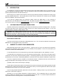
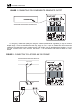
powered subwoofer
operation manual
KX-10
VX-760
Miller & Kreisel Sound, Inc.
9351 Deering Avenue
Chatsworth, CA 91311-5858 USA
(818) 701-7010 fax (818) 701-0369
www.mksound.com
©2004 Miller & Kreisel Sound, Inc.
POWERED SUBWOOFER
TABLE OF CONTENTS
1.
2.
3.
4.
5.
6.
7.
8.
9.
10.
11.
12.
13.
14.
SAFETY INSTRUCTIONS.......................................................................................3
INTRODUCTION................................................................................................4
VOLTAGE SELECTOR & POWER CORD.....................................................................4
WHERE TO LOCATE YOUR SUBWOOFER.................................................................4
SUBWOOFER HOOK-UP.......................................................................................5
WIRING WITH THE RCA JACK INPUTS..........................................................5
USING SPEAKER WIRE CONNECTIONS.........................................................7
SATELLITE SPEAKER WIRING OPTIONS..................................................8
PLUGGING IN THE SUBWOOFER......................................................................8
PHASE SWITCH..............................................................................................................9
USE OF THE "LOW PASS FILTER" CONTROL...........................................................9
USE OF THE "BYPASS" SWITCH.................................................................................9
USING MULTIPLE SUBWOOFERS...............................................................................10
HOME THEATRE USAGE..............................................................................................10
CONNECTING TO A SURROUND SOUND RECEIVER OR PROCESSOR.....10
TROUBLESHOOTING...............................................................................................10
IF YOU NEED SERVICE.................................................................................................12
M&K 5.1 CHANNEL & PRO-LOGIC SYSTEM SETUP GUIDE..................................12
SPECIFICATIONS....................................................................................................15
WIRING DIAGRAMS
FIGURE
FIGURE
FIGURE
FIGURE
1
2
3
4
CONNECTING TO A SURROUND PROCESSOR...............................................6
CONNECTING TO A STEREO AMP OR PREAMP..............................................6
TO AN AMP OR RECEIVER USING SPEAKER WIRES.....................................7
SATELLITE SPEAKER WIRING (OPTIONAL)......................................................8
Please record the following information for your records:
Serial Number:
Date of Purchase:
Dealer Name:
Dealer Address:
City/State/Zip:
Country:
Invoice Number:
2
POWERED SUBWOOFER
The exclamation point within an
equilateral triangle is intended to
alert the user of the presence of
important operating and maintenance (servicing) instructions in
the literature accompanying the
appliance.
1.
CAUTION:
TO PREVENT THE RISK OF ELECTRIC SHOCK,
DO NOT REMOVE COVER (OR BACK). NO USERSERVICEABLE PARTS INSIDE. REFER SERVICING TO QUALIFIED SERVICE PERSONNEL.
The lightning flash with arrowhead,
within an equilateral triangle, is
intended to alert the user of the
presence of uninsulated “dangerous
voltage” within the product's enclosure that may be of sufficient magnitude to constitute a risk of electric
shock to persons.
SAFETY INSTRUCTIONS
1.
READ INSTRUCTIONS - All safety and operating instructions should be read before this product is operated.
2.
RETAIN INSTRUCTIONS - The safety and operating instructions should be retained for future reference.
3.
HEED WARNINGS - All warnings on this product and in the operating instructions should be adhered to.
4.
FOLLOW INSTRUCTIONS - All operating and use instructions should be followed.
5.
ATTACHMENTS - Do not use attachments not recommended by the product manufacturer as they may cause hazards.
6.
WATER & MOISTURE - Do not use this product near water - for example, near a bathtub, washbowl, kitchen sink, or laundry
tub; in a wet basement; or near a swimming pool; and the like.
7.
ACCESSORIES - Do not place this product on an unstable cart, stand, tripod, bracket, or table. The product may fall, causing
serious injury to a child or adult, and serious damage to the product. Use only with accessories recommended by the
manufacturer, or sold with the product. Any mounting of the product should follow the manufacturer's instructions and should
use a mounting accessory recommended by the manufacturer.
8.
POWER SOURCE - This product should be operated only from the type of power source indicated on the marking label. If you
are unsure of the type of power supply to your home, consult your product dealer or local power company.
9.
OVERLOAD - Do not overload wall outlets or extension cords as this can result in a risk of fire or electric shock.
10. LIQUID ENTRY - Never spill any liquid of any kind on the product.
11. SERVICING - Do not attempt to service this product yourself. Opening or removing covers, including any over bottom or
side speaker drivers, may expose you to dangerous voltage or other hazards. Refer all service to qualified service personnel.
12. DAMAGE REQUIRING SERVICE - Unplug this product from the wall outlet and refer servicing to qualified personnel under the
following conditions:
•When the power-supply cord or plug is damaged.
•If liquid has been spilled, or objects have fallen into this product.
•If the product does not operate normally by following the operating instructions. Adjust only controls that are covered by the
operating instructions as an improper adjustment of other controls may result in damage and will often require extensive work by
a qualified technician to restore the product to its normal operation.
•If the product has been dropped or damaged in any way.
•When the product exhibits a distinct change in performance - this indicates a need for service.
13. REPLACEMENT PARTS - When replacement parts are required be sure the service technician has used replacement parts
specified by the manufacturer or have the same characteristics as the original part. Unauthorized substitutions may result in risk
of fire, electric shock, or other hazard.
14. SAFETY CHECK - Upon completion of any service or repairs to this product, ask the service technician to perform safety checks
to determine that the product is in proper operating condition.
15. HEAT - This product should be situated away from heat sources such as radiators, heat registers, stoves, or other products
(including amplifiers) that produce heat.
3
POWERED SUBWOOFER
2.
INTRODUCTION
Congratulations! You have just made perhaps the most exciting and dramatic addition that you could make to your
audio or multichannel audio/video system. The new dimension of deep and powerful bass provided by your M&K
K-series powered subwoofer will thrill and excite you.
We encourage you to read this owner's manual, as there is a great deal of information provided here to help you get
the best possible performance. This manual gives you basic hook-up instructions first, followed by more detailed
technical, installation, and service information.
If you have any questions about your subwoofer, please contact your M&K dealer, or call us directly at
(818) 701-7010, from 8:30 AM to 5:00 PM Pacific Time. We will be more than happy to help you with any question.
You can also access our web site at: www.mksound.com or send us an email to [email protected].
3.
VOLTAGE SELECTOR AND POWER CORD
Adjacent to the AC power cord receptacle on the back of the subwoofer you will find a "Voltage" switch. This switch
is pre-set at the factory for the proper local voltage, so there is no need to change the switch setting. For U.S. and
Canada operation, the proper voltage setting is 115V.
WARNING: This voltage selector must be set to the correct local voltage with the proper fuse installed.
Attempting to operate the subwoofer with the switch set to the incorrect position may damage the subwoofer
and there is a risk of fire. Any such damage is not covered by warranty.
If you have any questions regarding this switch, please contact your dealer or the M&K factory.
DETACHABLE POWER CORD
The KX10 and VX-760 are provided with a detachable power cord. This cord must be attached to the subwoofer
BEFORE the cord is plugged into the AC wall socket.
4.
WHERE TO LOCATE YOUR SUBWOOFER
M&K subwoofers perform well in most room locations. Unless your ear is a foot or two away from the subwoofer,
you will hear the deep bass coming exclusively from your satellite (or main) speakers. There is no need to place your
subwoofer in-between the satellite speakers.
For the best performance, we recommend that your subwoofer be placed against a wall, preferably in a corner.
The ideal place for the subwoofer is the corner with the best structural strength. If the corners are roughly equal in
construction, use the corner nearest the listening position. If the listening position is in the front half of the room, place
the subwoofer in a front corner. If the listening position is in the back of the room, place the subwoofer in a back corner.
Feel free to experiment with the orientation of the subwoofer cabinet. Sometimes the best sound results from
aiming the subwoofer's driver directly into the wall (1" to 2" from the wall itself).
If possible, avoid corners near doorways or openings.
Another option to find the best location for the subwoofer is to place the subwoofer at the listening position and walk
around the room. Stand in and near each corner. The location where you hear the tightest bass with the most impact
is probably the best location in the room for the subwoofer.
If you are using multiple subwoofers, place them in the same location. Stacking is best, but you can also put them
side by side. See Section 9, page 10.
Alternately, you can put multiple subwoofers in different locations. This is appropriate when you have limited
choices in locating the subwoofer and none of the available locations work well. Try to place multiple subwoofers at
equal distances from the listening position to avoid phase cancellation.
4
POWERED SUBWOOFER
Ultimately, the amount and quality of bass you get in your room are dependent on the room itself. Low frequency
bass sounds are affected most by the size of the room and the method of construction used to build it. All rooms are
different when it comes to reproducing bass, and in any given room, bass quantity and quality changes when the subwoofer is moved from one location to another.
A simple rule to remember is that you get more bass when you move the subwoofer towards any wall or corner.
Moving it away from a wall or corner gives you less bass. Remember that the floor also loads the subwoofer, and that
maximum bass is found with the woofer on the floor in a corner.
In some rooms, a corner location may excite resonance modes, resulting in a muddy or boomy sound. In these
rooms, a more central location along a wall, away from the corner, may give better results. If you experiment, try to find
a spot where no bass notes seem to overpower others and the overall sound is powerful and clean. The goal is to
achieve a smooth sound quality, with the entire bass spectrum equally prominent. In most rooms, this is directly in the
corner, not the center of the room.
Because the subwoofer generates a great deal of energy, its output may vibrate objects close to it. If you hear such
vibration, you may need to damp the vibration of nearby objects.
One subwoofer is sufficient in a stereo system because of the nature of human hearing. The ear-brain hearing
system is unable to locate the direction of bass sounds below approximately 150 Hz. The direction of low frequency
sounds (drums, basses, etc.) is determined by the higher frequency overtones and harmonics that are reproduced by
the satellite speakers.
The KX-10 powered subwoofer have an exceptionally sharp (36 dB/octave) low-pass filter to remove the midbass
and midrange frequencies, unwanted in a subwoofer. This makes your M&K subwoofer truly non-directional.
This M&K subwoofer is magnetically shielded. Shielding avoids magnetization of the shadow mask of the television's picture tube, which will distort the television's picture. If this ever happens to your set, turn it off and on a few times
to use the set's built-in degaussing circuitry. If the problem persists, contact a TV technician and ask him or her to use
an external degaussing coil.
No matter where you put the subwoofer, you must allow room for ventilation of its heatsink and backplate. The subwoofer's power amplifier is mounted on the backplate, and it generates heat.
1.
Leave clearance around the subwoofer's heatsink. Do not cover it with drapes.
2.
Do not place the subwoofer near baseboard heaters or forced air heating outlets.
3.
Do not use the subwoofer outdoors or in a humid environment.
Do not plug the subwoofer into an AC outlet until all system wiring is complete.
5.
SUBWOOFER HOOK-UP
There are two different ways to connect the subwoofer to your system. One uses speaker wire, and the other uses
interconnect cable with RCA-type jacks.
If your receiver or processor has a SUBWOOFER OUTPUT RCA-type jack, use it. This is the preferred connection
for your M&K subwoofer. If your component does not, skip to "USING SPEAKER WIRE CONNECTIONS" on page 7).
You cannot use "TAPE OUT" jacks to connect your subwoofer, because these jacks have a fixed output level that
does not change when you adjust the system volume control.
WIRING WITH THE RCA JACK INPUTS
The "LINE LEVEL" RCA jacks on the back panel of your subwoofer allow you to directly connect the subwoofer to
preamp-level components such as surround sound processors, preamplifiers, integrated amps and receivers with preamp outputs, Electronic High-Pass filters, crossovers, etc.
5
POWERED SUBWOOFER
FIGURE 1 - CONNECTING TO A COMPONENT’S SUBWOOFER OUTPUT
+
-
100Hz
80Hz
REFERENCE LEVEL
120Hz
140Hz
200Hz
60Hz
40Hz
MIN
BYPASS
LOW PASS FILTER
SUBWOOFER
SUB / MONO OUT
MAX
BASS LEVEL
SURROUND PROCESSOR OR RECEIVER
RIGHT
LEFT
LEFT
RIGHT
OFF AUTO ON
TO SPEAKERS
FROM AMP
VOLTAGE
115V
230V
This will give you better bass quality than using the speaker inputs, because it bypasses your amp or receiver's
amplifier stage. To connect the subwoofer in this way, simply run one or a pair of shielded RCA - RCA interconnect
cables from the output jacks on your component to the "LINE LEVEL" jacks on the Subwoofer's backplate. If you run
one cable, connect it to the “LEFT” input jack. See Figure 1. It is not necessary to use both input jacks on the subwoofer.
FIGURE 2 - CONNECTING TO A STEREO AMP OR PREAMP
SURROUND PROCESSOR OR RECEIVER
MAIN PRE OUT
-
+
100Hz
LEFT
RIGHT
80Hz
60Hz
40Hz
120Hz
140Hz
REFERENCE LEVEL
200Hz
MIN
BYPASS
LOW PASS FILTER
MAX
BASS LEVEL
TO SPEAKERS
VOLTAGE
230V
LEFT
RIGHT
MAIN INPUT
- LEFT +
- RIGHT +
+
+
6
115V
RIGHT
LEFT
LEFT
RIGHT
OFF AUTO ON
FROM AMP
POWERED SUBWOOFER
If you don't have a subwoofer output available, check to see if you have preamp outputs on your preamp, amp, or
processor to be able to use these inputs. If you have only one set of preamp outputs, use a Y-connector to feed both
the amplifier and the subwoofer. See Figure 2. Use a Y-connector to connect the signal to both the LEFT and RIGHT
inputs of the subwoofer. These inputs are summed to mono in the amplifier input stage of the subwoofer.
USING SPEAKER WIRE CONNECTIONS
Some M&K subwoofer owners hook up their subwoofer by connecting it to their receiver or amplifier using speaker
wires. To do so, you make the same kind of connections that you would use for your satellite (or main) speakers, except
that both the left and right channels go to the subwoofer. (If you are using two subwoofers, connect one channel only
to each subwoofer).
1.
2.
Run speaker wire between the Amplifier's Left channel output terminals and the subwoofer's Left
channel "FROM AMPLIFIER" terminals.
A.
Connect the Amplifier's Left channel Positive (+) terminal and the subwoofer's Left RED (+)
"FROM AMPLIFIER" terminal.
B.
Connect the Amplifier's Left channel Negative ( — ) terminal and the subwoofer's Left BLACK
( — ) "FROM AMPLIFIER" terminal.
Make matching connections for the Right channel. See Figure 3.
IMPORTANT NOTE FOR DOLBY PRO LOGIC SURROUND SYSTEMS: (NOT DOLBY DIGITAL 5.1)
When the subwoofer is connected to the Left and Right amplifier outputs, the Center channel WIDE/NORMAL switch
MUST be set to the NORMAL mode. If the switch is set to the WIDE mode, the bass content of the Center channel will
not be fed to the subwoofer, and a significant amount of bass in the program material will not be reproduced.
FIGURE 3 - WIRING TO AMP OR RECEIVER USING SPEAKER WIRES
AMPLIFIER OR RECEIVER
-
+
100Hz
80Hz
60Hz
40Hz
120Hz
140Hz
REFERENCE LEVEL
200Hz
MIN
BYPASS
LOW PASS FILTER
MAX
BASS LEVEL
TO SPEAKERS
RIGHT
LEFT
+
LEFT
+
RIGHT
OFF AUTO ON
FROM AMP
VOLTAGE
230V
115V
SATELLITE SPEAKER WIRING OPTIONS
If you use speaker wires to connect the subwoofer, you have two options for the Satellite speakers.
1.
Connect both the satellite speakers and the subwoofer direct to your amp or receiver, with one
set of wires running to the satellites and another set to the subwoofer. See Figure 4, below.
7
POWERED SUBWOOFER
2.
You can also connect your satellite speakers to the subwoofer. If you choose to do this, connect the
amplifier to the "From Amplifier" terminals on the back of the subwoofer and connect the satellite speakers
to the "To Speakers" terminals on the back of the subwoofer. For each channel, make sure that the Positive
(+) terminal on the amplifier is connected to the Positive (+) "From Amplifier" terminal (and the Negative
(-) terminals are connected), and that the Positive (+) "To Speakers" terminal is connected to the Positive
(+) terminal on the speaker (the Negative (-) terminals should also be connected.
If your amplifier has two sets of speaker outputs (e.g., A and B), you can connect the satellites to one set and the
subwoofer to the other. But if you get weak or no output when you connect your speaker this way, connect both sets of
speaker wires to the same output terminals.
FIGURE 4 - SATELLITE SPEAKER WIRING (OPTIONAL)
-
+
100Hz
80Hz
60Hz
40Hz
AMPLIFIER OR RECEIVER
120Hz
140Hz
REFERENCE LEVEL
200Hz
MIN
BYPASS
LOW PASS FILTER
MAX
BASS LEVEL
+
RIGHT
LEFT
TO SPEAKERS
FROM AMP
RIGHT
+
LEFT
LEFT
RIGHT
OFF AUTO ON
VOLTAGE
230V
115V
+
+
SATELLITE SPEAKERS
PLUGGING IN THE SUBWOOFER
Once all the speaker wires or preamp interconnect cables are in place, you are ready to plug in the subwoofer. Set
the "BASS LEVEL" control to "MIN". Attach the power cord to the receptacle on the subwoofer’s back panel. Then plug
the cord into the AC outlet.
Slide the power switch to either the “AUTO” or “ON” position. If you hear a “thump” from the subwoofer, this is the
normal sound of its power supply charging.
“AUTO” SWITCH POSITION
In the “AUTO” switch position, the subwoofer is in an idle condition when your system is turned off and no signal is
being fed to the subwoofer. When the subwoofer receives a signal from your receiver or processor, it automatically
switches on.
“ON” SWITCH POSITION
In the “ON” switch position, the subwoofer is fully active, whether or not your other components are turned on.
Do not plug the subwoofer into a switched outlet on another component.
8
POWERED SUBWOOFER
Now, play some music through your system to make sure that the satellite speakers are working properly. If they
are, carefully advance the "BASS LEVEL" control. The subwoofer should begin to play. Set the "BASS LEVEL" control
where the subwoofer sounds in balance with the satellite speakers. If the system is not working properly, unplug the
subwoofer and check all of your connections. Call your dealer or the factory if you cannot solve any problem.
6.
PHASE SWITCH
You are now almost finished with the basic set-up. But before you can sit down to enjoy your new subwoofer, you
need to perform one simple Phasing Test. This test insures optimum sound in the critical bass frequencies where your
subwoofer and Satellite speakers overlap.
Play a familiar CD, LP, or tape with steady, consistent bass. Listen carefully to the mid-bass (70 - 100 Hz) region
— the part of the spectrum where electric or string basses and drums are found. Then, slide the "PHASE" switch on the
SUBWOOFER's back panel from either (+) or (—).
Now listen to the same musical passage, concentrating on the mid-bass region. If you hear less bass, the original
connections were correct. If you hear more bass, the new connections are correct. If you have two subwoofers,
perform one test for each subwoofer. When you perform each test, make sure the other subwoofer is not operating by
either unplugging its input cable or its power cord.
Another method of setting phase uses a pink noise source and a spectrum analyzer. If you have these, place the
microphone at the main listening position and look at its display in the mid-bass region of 70 - 100 Hz. The wiring/ switch
position showing the most output in that region has the correct phase.
You need to perform this test because when satellite speakers are located separate from a subwoofer, each
speaker is at a different distance from your ear. In some cases, the difference will be just enough so that the output from
the subwoofer arrives out of phase with the output of the satellites. When this happens, that critical mid-bass is actually cancelled. You should re-do this test any time you move your speakers.
If you want to experiment further, you can move the satellite speakers either towards or away from your listening
position, making changes in small increments. This will focus the system's sound to its optimum. When you hear the
best balance between stereo image localization and maximum impact and output in the mid-bass, you have the ideal
location.
7.
USE OF THE "LOW PASS FILTER" CONTROL
The back panel control "LOW PASS FILTER" sets the upper rolloff point of the subwoofer, eliminating mid-bass and
midrange that are being reproduced by your satellite speakers. The control is a means of fine-tuning the transition
between your subwoofer and satellite speakers, and it provides a rolloff of 12 dB/octave up to 200 Hz, where the filter
shifts to 36 dB/octave. In most systems, including M&K satellites, 85 Hz gives the best blend. If you don't want to
experiment, set the control at 85 Hz. If you are using the K-5 / K-7 Satellites, set the control to 100Hz. If you are using
Xenon satellites (LCR45, LCR35, or LCR25), or the MP4512, set the control between 125 and 200 Hz.
The goal is to get a balanced acoustic output in your room. This is not necessarily the same as flat electrical output. Rooms typically reinforce bass frequencies around 100 Hz, so by leaving an electrical gap, you may actually get a
smooth acoustical response where it matters, in the room.
Think of this control as a mid-bass fine tuning adjustment that you set to achieve the best transition between the
satellite speakers and the subwoofer. When you hear a smooth sound overall, well balanced between the deep bass
and the rest of the audible spectrum, the control is set properly.
8.
USE OF THE "BYPASS" SETTING
If you have a THX, Dolby Digital, or DTS component with a built-in Low-Pass filter as part of its subwoofer output,
or if you are using a separate Electronic Crossover, set the “LOW PASS FILTER” switch on the back of the subwoofer
to “BYPASS” position. This bypasses the internal low-pass filter so that there is no interaction between the subwoofer’s
filter and your component’s filter. If you have any questions regarding the filters, please contact your M&K dealer or the
M&K factory.
9
POWERED SUBWOOFER
9.
USING MULTIPLE SUBWOOFERS
Using two (or more) subwoofers in your system gives you the ultimate in bass performance. You'll hear improved
impact and definition, as well as greater output and dynamic range.
If multiple subwoofers are used, place them in the same location. Stacking is best, but you can also put them side
by side. Alternately, you can put multiple subwoofers in different locations. This is appropriate when you have limited
choices in locating the subwoofer and none of the available locations work well. Try to place multiple subwoofers at
equal distances from the listening position to avoid phase cancellation.
With two subwoofers, simply run one speaker wire or interconnect to each subwoofer. Because the left and right
channel input signals are combined in the subwoofer's input stage, the only thing this changes is amplifier gain. To compensate, just set the "BASS LEVEL" control slightly higher.
10.
HOME THEATRE USAGE
If you are using your subwoofer in a multichannel Home Theatre system, make sure you are using the subwoofer
Output jack to connect your subwoofer. Check "Use of the Bypass Setting" above, as well as M&K's System Setup
Guide on page 12.
Compared to music sources, in some cases, you may prefer the subwoofer set to a higher playback level for video
sources. This may occur when video sources (especially older films and some television) have very little deep bass
present. You may also want to exaggerate the effect to make spectacular video sources even more impressive!
CONNECTING THE SUBWOOFER TO A SURROUND SOUND RECEIVER OR PROCESSOR:
The preferred connection from a surround sound amp or controller is from a SUBWOOFER OUTPUT (or MONO)
RCA jack. This connection insures that a full bass signal is fed to the subwoofer. If your component doesn't have a subwoofer output jack, connect the subwoofer to the front Left and Right channel speaker outputs (do not use the Center
channel speaker output).
VERY IMPORTANT: When the subwoofer is connected to the Left and Right amplifier outputs using speaker wires,
the Center channel WIDE/NORMAL switch MUST be set to the NORMAL mode. If the switch is set to the WIDE mode,
the bass content of the Center channel will not be fed to the subwoofer, and a significant amount of the bass in the material you are listening to will be lost.
11.
TROUBLESHOOTING
Your M&K subwoofer amplifier circuit provides high reliability, and, if necessary, easy modular replacement of parts.
This guide will help you to solve or diagnose most problems that can occur with your subwoofer. In the event that a fuse
blows, you must replace it with a fuse of the correct value to avoid a fire hazard and to maintain your warranty
protection.
A.
If your subwoofer has no output:
1.
Make sure that the subwoofer is plugged into an AC outlet and that the cord is securely
plugged into the back of the subwoofer.
2.
Make sure that the “POWER” switch is set to the “AUTO” or “ON” position. If you hear no
output with the switch set to “AUTO”, move the switch to the “ON” position.
3.
Check the "BASS LEVEL" control and make sure that it is set above the "MIN" position. Rotate
it clockwise if it is set to the "MIN" position.
4.
Check the red LED on the subwoofer's back panel. If the LED is not lit, check the AC fuse
next to the LED. Unplug the subwoofer before changing the fuse. See instructions on Page
12. If the element inside the fuse is broken, replace the fuse. If it blows again, contact your
dealer or M&K.
10
POWERED SUBWOOFER
B.
5.
If the red LED is lit, try this test: Turn the "BASS LEVEL" control to "MIN". Plug a standard
RCA cable into the "FROM PREAMP" jacks. Lightly touch the plug at the free end of the cable,
while slowly turning the "BASS LEVEL" control clockwise. If you hear noise from the
subwoofer when you touch the cable, the subwoofer is functioning. Look elsewhere in your
system for the problem. If you hear no noise, contact your dealer or M&K.
6.
Make sure that the input cables are OK. Double check your connections. If necessary, replace
any defective cables or speaker wires.
If, after operating the woofer at high volume levels for a long time, the woofer cuts out or becomes
intermittent:
Your subwoofer has a protection circuit that protects it from overheating. After hours of continuous
operation at extremely high volume levels, this circuit may cut off the power to the subwoofer. When
it activates, the sound may switch in and out rapidly, with a fluttering sound. If this happens, unplug the
unit and let it sit for at least half an hour. After that time, plug it back in. It should operate normally.
If you find this happens frequently, contact the factory for advice.
C.
If you are using the "FROM AMPLIFIER" terminals, and the subwoofer has very little output:
Make sure that the input cables are in phase. Reverse the (+) and the ( — ) connections for ONE
CHANNEL ONLY at the "FROM AMPLIFIER" terminals. If the problem remains, put the cables back as
they were. Then perform the test in Step 4.
D.
If the midbass range (the area of transition between Subwoofer and Satellite speakers) sounds weak:
Refer to Section 6, Phasing Test, on page 9. Reverse the (+) and ( — ) connections at the back of
BOTH Satellite speakers, OR switch the "PHASE" switch from (+) to ( — ) or vice versa. The wiring
configuration that gives the most bass is correct.
E.
If you are using the "FROM PREAMP" input terminals, and you hear a thump through the Subwoofer
every time you turn the system on:
F.
If you hear a persistent hum or buzz through the subwoofer:
Because the subwoofer reproduces the 60 Hz hum frequency, it is often blamed for causing hum that
originates elsewhere in the system. Always avoid running all speaker wires and RCA interconnect
cables near to AC cords and component power supplies. Wires and cables running close to AC lines
are a common source of hum. If necessary, reroute your cables.
To identify the source of hum, remove all input cables to the subwoofer, but leave it plugged into the
AC outlet. Carefully turn the "BASS LEVEL" control up towards the "MAX" position. If you hear hum
coming from the subwoofer's speaker driver, the subwoofer is the source of the hum. If you hear no
hum or less hum, the problem is probably coming from another component.
Hum can also be caused by AC ground loops. If the subwoofer is plugged into a separate AC outlet,
try plugging it into the same outlet used for your amplifier or receiver, or reverse the polarity of its AC
plug. If these suggestions do not solve your problems, contact your dealer or M&K.
G.
If there is an unusual sound coming from the subwoofer with no music playing:
Try removing the input cables as described in Step 5 above. If the noise disappears, it is coming from
another component. If it does not go away, contact your M&K dealer or the factory.
11
POWERED SUBWOOFER
IF YOU NEED TO REPLACE THE EXTERNAL FUSE:
Disconnect supply cord before changing fuse. Replace fuse only with same type.
Remove the fuse cap and inspect the fuse. Look carefully at the fuse. If the wire filament inside the glass is broken, replace the fuse ONLY with one of the identical size and value. Using a fuse of a larger value will void your warranty AND MAY CREATE A FIRE HAZARD. Plug the subwoofer back in. If it does not work, unplug it immediately, and
contact your dealer or M&K for service.
12.
IF YOU NEED SERVICE
Contact your dealer or M&K. Please have the unit's model and serial numbers (found on the back of the cabinet),
date of purchase, the name of your dealer, and a complete description of the problem. You can call M&K between 8:30
AM and 5:00 PM Pacific Time, Monday through Friday, at (818) 701-7010. If you call outside these hours, leave a message, and we will return your call. Alternatively, an e-mail can be sent to [email protected].
DO NOT RETURN YOUR SPEAKERS TO THE FACTORY FOR
SERVICE WITHOUT OBTAINING PRIOR AUTHORIZATION
All M&K powered subwoofers carry a five year limited parts and labor warranty. This warranty is transferable to subsequent owners up to three years from the date of original purchase, and it includes subwoofer amplifiers. It does not
cover abuse, misuse, repairs by unauthorized service stations, speakers without serial numbers, and speakers damaged in shipping or by accident. If you have any questions about the warranty, please contact M&K.
13.
M&K 5.1 MULTICHANNEL & PRO-LOGIC SYSTEM SETUP GUIDE
The 5 Most Important Items In System Setup:
1. Find the best location for the subwoofer for maximum output and flattest response
(usually the corner closest to the listening position)
2. Aim the front speakers (and the surrounds, if possible) vertically for the flattest
response and best imaging
3. Set all speakers to the Small setting for proper High-Pass and Low-Pass Filter
operation to get the lowest distortion and maximum dynamic range
4. Calibrate all speakers and the subwoofer to the identical level for proper imaging
and balance
5. Make sure all speakers are in phase for proper imaging and impact
These instructions will help you make sure that you cover all steps in setting up a 5.1 multichannel or Pro-Logic surround sound system. In addition to following this list, make certain that you study and understand the owner’s manual
for each and every component used in the system, especially the processor/receiver’s manual. Have fun and good luck!
A useful tool for system setup is the DVD called Video Essentials. If you don’t have one, you can order it by visiting
www.videoessentials.com.
Here are the instructions for speaker setup.
A.
Locate the front speakers. The left, right, and center speakers should be equidistant from the main
listening position. Try to set up the speakers so that they are reasonably symmetrical to room surfaces.
A tape measure may be very helpful.
B.
Locate the subwoofer.
12
POWERED SUBWOOFER
1.
The best place for the subwoofer is the corner with the best structural strength. If the corners
are roughly equal in construction, use the corner nearest the listening position. If the listening
position is in the front half of the room, place the subwoofer in a front corner. If it is in the back
of the room, place the subwoofer in a back corner. If possible, avoid corners near doorways
or openings.
2.
If you are willing to experiment, another option is to place the subwoofer at the listening
position and walk around the room. Stand in and near each corner. The location where you
hear the tightest bass with the most impact is probably the best location in the room for the
subwoofer.
3.
If multiple subwoofers are used, place them in the same location. Stacking is best, but you
can also put them side by side.
Another option for multiple subwoofers is to place them in different locations. This is appropriate when
you have limited choices in locating the subwoofer and none of the available locations work well. Try
to place multiple subwoofers at equal distances from the listening position to avoid phase cancellation.
C.
Locate the surrounds. Determine the best position in the room. It will probably be the position used
for THX speaker, directly to the right and left of the main listening position on the side walls (so that a
listener in the center seat is directly between the speakers). If that doesn’t work or is not practical
because of the room, try these locations: on the ceiling; on the back wall, or in the back corners (using
an M&K ST Corner bracket).
D.
Install all wiring and interconnects.
E.
Aim the front speakers (this is a must for THX front speakers). Use a laser level to align each
speaker. Place the level on the flat surface between the midranges and tweeters that is roughly in the
center of the front baffle. The red dot of the laser should be aligned to the center of the listener’s fore
head at ear height. Make sure that the volunteer who sits in the main listening position keeps their eyes
closed!
Make sure that you aim the left and right speakers in both the horizontal and vertical planes. Horizontal
toe-in is important for the best possible imaging.
F.
If you have a Dolby Digital AC-3 5.1 channel processor/receiver, follow these instructions. If you have
a Pro-Logic processor/receiver, go to item 7 below.
SPECIAL NOTE: Always check the processor/receiver’s owner’s manual. Different manufacturers use different
descriptions for the same function, and sometimes the same description for different functions!. Your
component may use terminology different from that used below.
G.
1.
High-Pass Filters: All Dolby Digital processor/receivers have built-in high-pass filters for the
Left, Center, Right, Left Surround, and Right Surround channels. Always turn these filters ON
by using the SMALL setting. If you have a THX component, use the THX setting. See the
owner’s manual of the processor/receiver for instructions.
2.
Bass Management: If the processor/receiver has a setting to turn the Subwoofer off or on,
make sure that it is set to SUBWOOFER YES or ON.
3.
Dialog Normalization: If your component has this function, turn it off to avoid any possible
effect on sound quality.
4.
THX Dolby Digital units have an adjustable limiter for the subwoofer feed, called “Bass Peak
Level Management”. Turn it off, or set it for the highest possible level. M&K subwoofers do
not need this limiter.
If you have a Pro-Logic only processor/receiver, follow these instructions.
13
POWERED SUBWOOFER
SPECIAL NOTE: Always check the processor/receiver/receiver’s owner’s manual. Different manufacturers use
different descriptions for the same function, and sometimes the same description for different functions! Your
component may use terminology different from that used below.
H.
1.
If the component has high-pass filters for the Left, Center, and Right channels (usually only
THX components have these filters), they should be turned on or set to THX (if you have a
choice, use the frequency closest to 80 Hz. The surround channels in a Pro-Logic only
system do not have switchable filters.
2.
Set the center channel to Normal, unless you have a THX controller. With a THX controller,
set the center channel to the THX setting.
3.
Turn off all limiters and compressors, auto azimuth controls, auto balance controls, etc.
4.
If the processor/receiver/receiver has an input level control, calibrate it per the manufacturer’s
instructions.
5.
If the component has a digital input, and you are using a source component with a digital
output, always use the digital input, not the analog input.
Set levels for each channel. You can take a measurement at the listening position to establish the
reference level, but it is usually more accurate to take levels at about one meter from each speaker.
Set all channels to exactly the same level.
Use a Sound Level Meter. Point it directly at the speaker being measured. Set all channels to the same
level, using the processor/receiver/receiver’s internal test signal. Set the meter to “C” weighting and
“Slow” response. Set the levels to 75 dB if you have a THX processor/receiver/receiver or are using
the Video Essentials disc as a source for setting levels.
NOTE: If you using identical speakers anywhere in your system (e.g., S-150THX speakers for the left, center,
and right channels), all of those channels should be set to the same level. If your meter measures a different
level, it is probably a limitation of this type of meter measurement method and not an actual audible level
difference. Set the channels using identical speakers to the same level, unless you actually hear a difference
later when you are doing listening to verify the system setup.
I.
Check phase. Make sure that all five main channel speakers are wired in phase. The Video Essentials
disc has tests for main speaker phase.
J.
Make sure that the subwoofer and main speakers are in phase at the 80 Hz crossover point. Listen to
something with a consistent bass line around 80 Hz while a partner switches the “Phase” control on the
subwoofer from “+” to “-”. The switch position that results in the greatest bass at the listening position
is the correct setting.
K.
Play something that is familiar to you through the system to verify the system’s overall performance. If
something does no sound right, recheck your connections and settings. Re-measure, re-check,
re-align.
L.
Switch the processor/receiver to each input that you will use. Check your settings for each input and
each mode. Some processor/receivers require that you enter settings separately for each mode
and/or input.
M.
Before playing the system, check levels and speaker alignment one last time. Make sure that you write
down all processor settings for future reference.
14
POWERED SUBWOOFER
14.
SPECIFICATIONS
KX-10
ENCLOSURE TYPE:
WOOFER:
POWER RATING:
FREQUENCY RESPONSE:
DIMENSIONS (HxWxD):
WEIGHT:
Sealed Box
Single 8" Driver
150 watts RMS
35Hz - 200Hz ± 3dB
10-1/8” x 13-3/4” x 10”
21 lbs./9.53 kg.
VX-760
ENCLOSURE TYPE:
WOOFER:
POWER RATING:
Sealed Box
Single 12" Driver
150 watts RMS
KX-10/VX-760 subwoofer manual
10/29/04
pt/qrk
PN # 70052
15