1
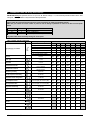
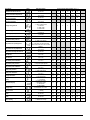
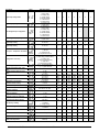
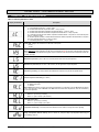
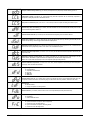
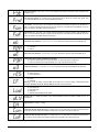
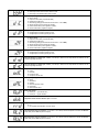
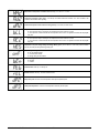
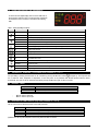
UNIVERSAL–R GREAT NEW FEATURES on the Universal-R DUAL VOLTAGE 12V & 230V POWER SUPPLY Both low (12Vac/dc) and high voltage (230Vac) power supply inputs are present in this single controller (see the rear connections of the device). QUICK AND SAFE START UP FUNCTION SELECTION Direct selection of the controller functionality by pressing a dedicated button, during a fixed time interval, at start up. NEW FRONT FASCIA DESIGN Display with illuminated icons to indicate loads, alarms, status indications. Six buttons give direct access to main functions and menu. DOUBLE EVAPORATOR DEFROST FUNCTION A new feature allows defrost control of twin evaporators. The 4th (AUX) relay and probe 3 (Pb3) control defrost of the second evaporator. Only when both have terminated will refrigeration re-start. Independent parameters are present to control the second evaporator. ON/OFF BUTTON Dedicated button to switch the controller on and off. 1592031000 Univ-R4 GB - r1.0 - 08.04.2011.doc Universal-R 2/19 1. INDEX 1. 2. 3. 4. 5. 6. 7. 8. 9. 10. 11. 12. 13. 14. 15. 16. 17. 18. 19. 20. 21. INDEX____________________________________________________________________________________3 GENERAL WARNING _______________________________________________________________________4 GENERAL DESCRIPTION ___________________________________________________________________4 QUICK START UP PROCEDURE – Up and running in 5 easy steps __________________________________5 TYPICAL CONNECTIONS - FOR GENERAL GUIDANCE ONLY _____________________________________6 PARAMETER TABLE and factory default settings _________________________________________________7 PARAMETERS – THEIR FUNCTIONS IN DETAIL _______________________________________________10 BUTTONS AND THEIR FUNCTIONS __________________________________________________________15 PROGRAMMING MODE ____________________________________________________________________15 OTHER FEATURES OF THE UNIVERSAL-R ___________________________________________________16 THERMOSTAT OVERRIDE ( not available when parameter tC = 1 or 7 ) ______________________________16 DEFROST TYPES _________________________________________________________________________16 EVAPORATOR FAN CONTROL (only when parameter tC = 5 or 6) __________________________________16 SPECIAL APPLICATIONS – DEAD BAND CONTROL ____________________________________________17 ALARMS _________________________________________________________________________________17 REMOVING SECURITY LEVEL PROTECTION __________________________________________________17 MOUNTING ______________________________________________________________________________18 ELECTRICAL CONNECTIONS _______________________________________________________________18 PROBES_________________________________________________________________________________18 TECHNICAL DATA ________________________________________________________________________18 FAULT FINDING _________________________________________________________________________19 1592031000 Univ-R4 GB - r1.0 - 08.04.2011.doc Universal-R 3/19 2. GENERAL WARNING WARNING: The Universal-R should always be installed by a suitable qualified person, in accordance with best electrical and refrigeration practice. Take time to read the instructions. Do not exceed the relay ratings. The Universal-R should not be considered a safety device, use suitable safety cutout devices when appropriate. This manual is part of the product and should be kept near the instrument for easy and quick reference. The instrument shall not be used for purposes different from those described hereunder. It cannot be used as a safety device. Check the application limits before proceeding. 2.1 3. SAFETY PRECAUTIONS Check the supply voltage is correct before connecting the instrument. Do not expose to water or moisture: use the controller only within the operating limits avoiding sudden temperature changes with high atmospheric humidity to prevent formation of condensation Warning: Disconnect all electrical connections before any kind of maintenance. The instrument must not be opened. Fit the probes where they are not accessible by the End User. In case of failure or faulty operation send the instrument back to the distributor with a detailed description of the fault. Do not exceed the maximum current that can be applied to each relay (see Technical Data). Ensure that the wires for probes, electrical loads and the power supply are separated and far enough away to each other, without crossing or intertwining. In case of applications in industrial environments, the use of mains filters (our mod. DIXL930) in parallel with inductive loads could be useful. Heating applications – Do not exceed 105°C with the NTC probes supplied. For higher temperatures (up to a maximum of 150°C) use special PTC probes (e.g. our Part No. DIXL957). GENERAL DESCRIPTION Model Universal-R is a 71x29 mm format microprocessor based controller, suitable for applications on high, medium or low temperature refrigeration units. It is provided with three relay outputs to control compressor, defrost - which can be both electrical or hot gas - and evaporator fans. It can work with PTC or NTC probes. Where defrost is being terminated by time, it can operate with just one thermostat probe. Where defrost is being terminated by temperature, it has an input for an evaporator probe(s). The Universal-R is equipped with an internal alarm buzzer, a flashing visual alarm as well as a 4th relay (volt free) that can be configured as Auxiliary or Alarm, to control a heater in Dead Band control (see parameter oAC) or to control the defrosting of a second evaporator (when “tC” parameter is set to 6). Double evaporator defrost: When tC=6, the controller is set up to defrost twin evaporators. Defrost of both evaporators will start simultaneously but each evaporator will terminate defrost individually on temperature. Only when both evaporators have terminated defrost, will the controller revert to refrigeration. Each instrument is fully configurable through special parameters that can be easily programmed through the keypad. 1592031000 Univ-R4 GB - r1.0 - 08.04.2011.doc Universal-R 4/19 4. QUICK START UP PROCEDURE – Up and running in 5 easy steps This Quick Start Up section is designed to get you up and running with the minimum of fuss. Just follow these 5 simple steps. Install the new Universal-R, connect the correct number of probes and connect the wiring - See below: 1. Table 1: parameter tC settings 2. Section 5: Typical connections STEP 1 Turn on power, STEP 2 THEN WITHIN 1 MINUTE COMPLETE STEPS 3, 4 AND 5. Press the “DOWN” key for 3 seconds and the controller will automatically recognise and adjust itself to the type of probes connected. (The display briefly shows tPd followed by ntC or PtC). Press the “AUX/tC” key for 3 seconds and the setting of parameter tC is displayed. Use the UP or DOWN keys to adjust to required setting then confirm by pressing SET (see table 1 below). Press SET for 3 seconds until the °C or °F icon starts to flash, then adjust the SET POINT using the UP or DOWN keys, then press SET again to confirm. STEP 3 STEP 4 STEP 5 1. 2. 3. Notes: All probes must be of the same type, either PTC or NTC; Probes must be at between -50 to 60°C for auto recognition to work; If 1 minute expires before you have completed quick set up, either turn OFF / ON power to start set up again or enter parameter as per the instructions and adjust your parameter settings manually (see Section 9). Table 1: parameter “tC” settings Parameter Type of Control tC 1 On / Off thermostat – Cooling 2 Off cycle defrost (timed) 3 Electrical / Hot Gas defrost, time initiated / time terminated 4 Electrical / Hot Gas defrost, time initiated / temperature terminated 5 Electrical / Hot Gas defrost, time initiated / temperature terminated + evap. fan delay 6 Double evaporators applications (similar to setting 5) 7 On / Off thermostat – Heating Required probes x1 x1 x1 x2 x2 x3 x1 Note: “tC” settings 3, 4, 5 and 6 use Electrical defrost as default. Hot Gas is possible by setting parameter “tdF” for gas defrost. Settings 1, 2, 3 & 7 do not require that the 2nd and the 3rd probe to be fitted. Take note of the number of probes to be connected for the selected application. As you change parameter tC, defaults change and should be approximately correct for that application but we strongly recommend you check all parameter default values listed in these instructions to ensure they suit your particular application and make further adjustments if necessary. Read the following sections for information about programming. 1592031000 Univ-R4 GB - r1.0 - 08.04.2011.doc Universal-R 5/19 5. TYPICAL CONNECTIONS - FOR GENERAL GUIDANCE ONLY Table 2: typical connections Parameter tC = 1, 2 On / Off thermostat or Off Cycle Defrost Controller. Parameter tC = 3 Forced defrost controller, time initiated & time terminated. Parameter tC = 4 Forced defrost controller, time initiated & temperature terminated. Parameter tC = 5 Forced defrost controller, time initiated & temperature terminated with evaporator fan delay after defrost. Parameter tC = 6 Double evaporator applications. Parameter tC = 7 Heating applications. 1592031000 Univ-R4 GB - r1.0 - 08.04.2011.doc Universal-R 6/19 6. PARAMETER TABLE and factory default settings IMPORTANT: Always set parameter “tC” first. As you move “tC” between settings 1 to 7, all non-relevant parameters will be masked. After setting “tC”, it will be possible to modify all the other relevant parameters. WARNING!! Always switch the power OFF and then ON at the end of programming to update any parameter changes. Make sure you connect the correct number of probes to suit the setting of parameter tC. Failure to do this will cause probe alarms tC setting 1, 2, 3 and 7 4, 5 6 No. Probes 1 2 3 Type Room only Room + Evaporator 1 Room + Evaporator 1 + Evaporator 2 Any probe alarms can be cleared by turning off / on the power Table 3: default controller parameters Description Type (category) of controller Label Adjustment Range 1 = On / Off Thermostat 2 = Off cycle defrost 3 = Time / time defrost 4 = Time / temp defrost 5 = Time / temp defrost + fan delay 6 = Double evaporator defrost 7 = On / Off Thermostat for heating Set Point LS to US 0 = PTC 1 = NTC 0.1 to 25.5C; 1 to 45°F -55C to Set Point; -67°F to Set Point Set Point to 150C; Set Point to 302°F Probe type Differential Minimum Set Point limit Maximum Set Point limit Anti-short cycle delay Second compressor start delay Temperature alarm configuration High temperature alarm Low temperature alarm Factory defaults with parameter “tC” 1- 7 1 2 3 4 5 6 2.0°C; 36°F 2.0°C; 36°F 2.0°C; 36°F 2.0°C; 36°F 2.0°C; 36°F 2.0°C; 36°F 7 40.0°C; 104°F 1 1 1 1 1 1 1 2.0°C; 2.0°C; 2.0°C; 2.0°C; 2.0°C; 2.0°C; 2.0°C; 2°F 2°F 2°F 2°F 2°F 2°F 2°F -50.0°C; -50.0°C; -50.0°C; -50.0°C; -50.0°C; -50.0°C; -50.0°C; -58°F -58°F -58°F -58°F -58°F -58°F -58°F 50.0°C; 50.0°C; 50.0°C; 50.0°C; 50.0°C; 50.0°C; 50.0°C; 122°F 122°F 122°F 122°F 122°F 122°F 122°F 0 to 50 min 1 1 1 1 1 0 to 255 sec 2 2 2 2 2 1 1 1 1 1 0 = Relative to Set Point; 1 = Absolute 0 to 50C (Rel); ALL to 150C (Abs); 0 to 90F (Rel); ALL to 302C (Abs) 0 to 50C (Rel); -55C to ALU (Abs); 0 to 90C (Rel); -67C to ALU (Abs) 1 0 1 1 50.0°C; 50.0°C; 50.0°C; 50.0°C; 50.0°C; 50.0°C; 50.0°C; 122°F 122°F 122°F 122°F 122°F 122°F 122°F -50.0°C; -50.0°C; -50.0°C; -50.0°C; -50.0°C; -50.0°C; -50.0°C; -58°F -58°F -58°F -58°F -58°F -58°F -58°F Temperature alarm delay 0 to 255 min 15 15 15 15 15 15 15 Delay of temperature alarm at start up 0 to 720 min 90 90 90 90 90 90 90 Outputs activation delay at start up 0 to 255 min 0 0 0 0 0 0 0 Thermostat override 0 to 990 min 0 0 0 0 0 Set point for continuous cycle -55 to 150°C; -67 to 302°F 2.0°C; 36°F 2.0°C; 36°F 2.0°C; 36°F 2.0°C; 36°F 2.0°C; 36°F Defrost delay after thermostat override Interval between defrosts Delay start of defrost 1592031000 Univ-R4 GB - r1.0 - 08.04.2011.doc 0 to 255 min 2 2 2 2 2 1 to 250 hours 4 6 6 6 6 0 to 255 min 0 0 0 0 0 Universal-R 7/19 Description Label Adjustment Range Factory defaults with parameter “tC” 1- 7 Maximum duration of defrost 0 to 255 min 15 15 30 30 30 Defrost termination temperature -55 to 50C; -67 to 122°F 8.0°C 46°F 8.0°C 46°F 8.0°C 46°F 8.0°C 46°F 8.0°C 46°F Maximum duration of defrost (second evaporator) Defrost termination temperature (second evaporator) Display during defrost 0 to 255 min 30 -55 to 50C; -67 to 122°F 0 = Real temp. 1 = Temp. at defrost start 2 = Set Point 3 = “DEF” label 4 = “DEG” label 8.0°C 46°F 3 3 3 3 3 10 Defrost display time out 0 to 255 min 10 10 10 10 Defrost type (forced) 0 = Electrical 1 = Hot Gas 0 0 0 0 0 to 255 min 0 0 2 2 0 0 0 0 1 1 25°C; 77°F 25°C; 77°F Drain down time First defrost after power on Evaporator fan operating mode Evaporator fan stop temperature 1 = Immediate 0 = After normal interval 0 to 3 (1 = Fan always on apart from during defrost. See section 10 for info. on other settings ) -55 to 50C; -67 to 122°F 0 Evaporator fan delay after defrost 0 to 255 min 7 7 Fan ON time 0 to 15 min 0 0 Fan Off time 0 to 15 min -12.0 to 12.0C; -21 to 21F 0 = evaporator probe not present 1 = evaporator probe present -12.0 to 12.0C; -21 to 21F 0 = third probe not present, 1 = third probe present. -12.0 to 12.0C; -21 to 21F 0 = With decimal point 1 = No decimal point 0 = Celsius 1 = Fahrenheit 0 = Thermostat probe 1 = Evaporator probe 2 = Third probe 3 = SET-POINT 0.0°C; 0°F Display delay 0 to 20min0sec, res. 10sec Type of action 0 = cooling 1 = heating 0 0 0 to 255 min 15 0 to 255 min 0 = Mute buzzer only 1 = Mute buzzer & relay Thermostat probe calibration Evaporator probe presence Evaporator probe calibration Third probe presence Third probe calibration Display Resolution Temperature measurement unit (°C/°F) Instrument display Compressor ON time with faulty probe Compressor OFF time with faulty probe Alarm muting configuration for buzzer & relay 1592031000 Univ-R4 GB - r1.0 - 08.04.2011.doc Universal-R 0.0°C; 0°F 0.0°C; 0°F 0.0°C; 0°F 0 0 0.0°C; 0°F 0.0°C; 0°F 1 1 1 0.0°C; 0°F 0.0°C; 0°F 0.0°C; 0°F 0.0°C; 0°F 1 1 1 1 1 1 0.0°C; 0°F 0.0°C; 0°F 0.0°C; 0°F 0.0°C; 0°F 0.0°C; 0°F 0.0°C; 0°F 0 0 0 0 0 0 0 0 0 0 0 0 0 0 0 0 0 0 0 0 0 0 0 0 0 0 0 0 15 15 15 15 15 0 30 30 30 30 30 30 30 1 1 1 1 1 1 1 8/19 Description Label Adjustment Range 0 = Start defrost 1 = Door switch 2 = Auxiliary relay 3 = Energy saving 4 = Remote On/OFF 5 = Generic alarm 6 = Serious alarm 0 = Closed circuit 1 = Open circuit 0 = Start defrost 1 = Door switch 2 = Auxiliary relay 3 = Energy saving 4 = Remote On/OFF 5 = Generic alarm 6 = Serious alarm 0 = Closed circuit 1 = Open circuit Digital input configuration Digital input polarity Second Digital input configuration Second Digital input polarity Factory defaults with parameter “tC” 1- 7 5 5 5 5 5 5 5 0 0 0 0 0 0 0 5 5 5 5 5 5 0 0 0 0 0 0 Digital input 1 delay 0 to 255 min 0 0 0 0 0 0 0 Digital input 2 delay 0 to 255 min 0 0 0 0 0 0 0 0 0 0 0 0 0 0 0 0 0 0 0 Door open – compressor / fan status Configuration of 4th relay Alarm relay polarity 0 = No change 1 = Fan off 2 = Compressor off 3 = Compressor & Fan off 0 = Alarm relay 1 = Heater relay (for Neutral Zone) 2 = Auxiliary relay 3 = Second compressor relay 4 = Light output 5 = Second defrost output 0 = [11 -12] closed with alarm 1 = [11 -12] open with alarm Exclude temperature alarm - door open Restart regulation with door open alarm Low temperature alarm of condenser High temperature alarm of condenser Differential for temperature condenser alarm recovery Condenser temperature alarm delay Condenser temperature alarm exclusion at start up Compressor off with low temperature alarm of condenser Compressor off with high temperature alarm of condenser Temperature deviation from normal Set Point during Energy Saving ON / OFF key enabling Buzzer enabling 0 0 0 0 0 0 0 to 255 min 20 20 20 20 20 20 20 0 = No 1 = Yes -55 to 150°C; -67 to 302°F -55 to 150°C; -67 to 302°F 0.1 to 25.5°C; 1 to 45°F 0 0 0 0 0 0 0 -40°C; -40°F 110°C; 230°F 5°C; 5°F -40°C; -40°F 110°C; 230°F 5°C; 5°F -40°C; -40°F 110°C; 230°F 5°C; 5°F -40°C; -40°F 110°C; 230°F 5°C; 5°F -40°C; -40°F 110°C; 230°F 5°C; 5°F 0 to 254 min, 255 = nU 15 15 15 15 15 0 to 720 min, res.10min 90 90 90 90 90 0 0 0 0 0 0 = No 1 = Yes 0 = No 1 = Yes -30.0 to 30°C; -54 to 54°F 0 = Disabled 1 = Enabled 2 = Energy saving 0 = Disabled 1 = Enabled 0 0 0 0 0 0 0°C; 0°F 0°C; 0°F 0°C; 0°F 0°C; 0°F 0°C; 0°F 0°C; 0°F 0°C; 0°F 0 0 0 0 0 0 0 1 1 1 1 1 1 1 For factory use only - - - - - - - Software release number Read only - - - - - - - Evaporator probe temperature Read only - - - Third probe temperature Read only - - - - - - Parameter table 1592031000 Univ-R4 GB - r1.0 - 08.04.2011.doc Universal-R 9/19 READ ON IF YOU NEED MORE DETAIL 7. PARAMETERS – THEIR FUNCTIONS IN DETAIL Table 4: controller parameters in detail Display visualisation Description Type of Controller: tells the Universal-UDS which type of controller it will be operating as. 1 = on/off refrigeration thermostat – 1 relay & 1 probe; 2 = Combined thermostat with off cycle defrost timer – 1 relay & 1 probe; 3 = Combined thermostat with time initiated & time terminated defrost – 2 relays & 1 probe; 4 = Combined thermostat with time initiated & temperature terminated defrost – 2 relays & 2 probes; 5 = Combined thermostat with time initiated, temperature terminated defrost + evaporator fan control with delay after defrost – 3 relays & 2 probes; 6 = Double evaporator operations: combined thermostat with time initiated, temperatures terminated defrost + evaporator fans control with delay after defrost – 3 relays & 3 probes; 7 = on/off heating thermostat – 1 relay & 1 probe. Probe Type: configures the controller to work with PTC or NTC probes. 0 = PTC, 1 = NTC. Differential: (0.2°C to 12.0°C) sets the degrees above Set Point at which the compressor cuts in. Note: when tC = 7 (heating applications) the tC value is automatically set below the Set Point. If the temperature decreases and reaches set point minus differential the regulation output is activated and then turned off when the temperature reaches the set point value again. Minimum set point limit: (-55°C to SET or -67°F to SET) sets the lower limit of set point adjustment. Maximum set point limit: (SET to 150°C or SET to 302°F) sets the upper limit of set point adjustment. Anti-short cycle delay: (0 to 50min) minimum interval between the compressor stop and the next possible restart. Second compressor start delay: (0 to 255sec) Temperature alarm configuration: 0 = Related to Set Point; 1 = Absolute. Note: Related means alarms are linked to the Set Point and will follow it if it is adjusted. In this case ALU & ALL set degrees over & under Set Point for alarm. Absolute means ALU & ALL will set fixed alarm temperatures, which are not affected by any Set Point adjustment. High temperature alarm: ALC = 0 → [0 to 50°C] or [0 to 90°F]; ALC = 1 → [ALL to 150°C] or [ALL to 302°F]. Low temperature alarm: ALC = 0 → [0 to 50°C] or [0 to 90°F]; ALC = 1 → [-55°C to ALU] or [-67 to ALU]. Temperature alarm delay: (0 to 255min) time interval between an alarm condition occurring and the alarm signalling. Delay of temperature alarm at start-up: (from 0 to 720min; res. 10min) time delay of any temperature alarm during pull down following “power on”. 1592031000 Univ-R4 GB - r1.0 - 08.04.2011.doc Universal-R 10/19 Outputs activation delay at start up: (0 to 255min) time delay before any output relay activates following “power on”. Thermostat override: (0 to 990min; res. 10min) period during which the compressor will run continuously, irrespective of temperature. Setting this parameter to 0 inhibit this function. Set point for continuous cycle: (-55 to 150 °C or -67 to 302°F) it sets the set point used during the continuous cycle. Defrost delay after fast freezing: (0 to 255min) time interval between the end of the thermostat override period and the start of the following defrost related to it. Interval between defrosts: (0 to 255hours) time interval between the beginning of two consecutive defrosts. Delay start of defrost: (0 to 255min) delay between reaching the defrost interval time (as defined by parameter idF) and the defrost actually starting. Used to stagger defrosts between multiple systems. (Maximum) duration of defrost: (0 to 255min) time duration of defrost when only one probe is in use, or defrost time out override when second (evaporator) probe is in use. Set it to zero to disable defrost cycles. Defrost termination temperature: (-55 to 50°C or -67 to 122°F) sets the defrost termination temperature. Measured by the evaporator probe. (Maximum) length for second defrost: (0 to 255min) when P3P = 0, (not evaporator probe: timed defrost) it sets the defrost duration, when P3P = 1 (defrost end based on temperature) it sets the maximum length for defrost. Note: The P3 probe will be automatically set as second evaporator probe by the tC parameter. Second termination temperature: (-55 to 50°C or -67 to 122°F) sets the temperature measured by the second evaporator probe (P3), which causes the end of defrost. Display during defrost: 0 = real temperature; 1 = temperature at defrost start; 2 = set point; 3 = dEF label; 4 = dEG label. Defrost display time out: (0 to 250min) after a defrost, the controller will revert to current temperature display when the temperature is back down within its normal working range, or after the time set in this parameter, whichever is the sooner. Defrost type: 0 = electrical heater; 1 = hot gas, compressor runs during defrost. Drain down time: (0 to 255min) drain down time. Runs concurrently with Fnd (Fan delay after defrost time). First defrost after power-on: 0 = immediately; 1 = after the idF interval time. Fan operating mode: 0 = cycles on/off with the compressor, OFF during defrost; 1 = continuous mode, OFF during defrost; 2 = cycles on/off with the compressor, ON during defrost; 3 = continuous mode, ON during defrost; 1592031000 Univ-R4 GB - r1.0 - 08.04.2011.doc Universal-R 11/19 Fan stop temperature: (-55 to 50°C or -67 to 122°F) temperature above which the evaporator fan stops (during the normal refrigeration cycle). Fan delay after defrost: (0 to 255min) the time interval between end of defrost and evaporator fans starting. Runs concurrently with Fdt (Drain down time). Always keep Fnd longer that Fdt. Fan ON time: (0 to 15min) used to set an On/Off cycle of the evaporator fans while the compressor is off. With FnC = 0 or FnC = 2, it sets the evaporator fan ON cycling time when the compressor is OFF. With Fon = 0 and FoF ≠ 0, the fans are always off. With Fon = 0 and FoF = 0 the fans are always off. Fan OFF time: (0 to 15min) used to set an On/Off cycle of the evaporator fans while the compressor is off. With FnC = 0 or FnC = 2, it sets the evaporator fan OFF cycling time when the compressor is OFF. With Fon = 0 and FoF ≠ 0, the fans are always off. With Fon = 0 and FoF = 0 the fans are always off. Thermostat probe calibration: (-12.0 to 12.0°C or -21 to 21°F) adjustment for thermostat probe (named Room) offset. Evaporator probe presence (probe named Evap on the label): 0 = not present; 1 = present. Evaporator probe calibration: (-12.0 to 12.0°C or -21 to 21°F) adjustment for evaporator probe (named Evap) offset. Third probe presence (probe named Evap.2 on the label): 0 = not present, the third input (the one signed with label “D.I.2 / Pb3”) Input operates as digital input; 1 = present, the third input (the one signed with label “D.I.2 / Pb3”) Input operates as third probe. Third probe calibration: (-12.0 to 12.0°C or -21 to 21°F) adjustment for third probe (named Evap.2 on the label) offset. Display resolution: 0 = with decimal point; 1 = without decimal point. Temperature measurement unit: 0 = Celsius; 1 = Fahrenheit. Warning: If you alter the setting of parameter rES ( decimal point on/off ) re-check the settings of all temperature related parameters Set Point, HY, LS, US, ALU, ALL, dtE, FSt, ot & oE, as they can be effected. Probe for Display: 0 = Thermostat probe; 1 = Evaporator probe; 2 = Third probe; 3 = DISPLAY ONLY SHOWS THE SET-POINT. Display delay: (0 ÷ 20min0sec; resolution 10 sec) when the temperature increases, the display is updated of 1°C or 1°F after this time. Type of action: 0 = cooling; 1 = heating. Compressor ON time with faulty probe: (0 to 255min) If there is a P1 probe failure the controller will automatically cycle the compressor on/off according to Con & CoF to maintain basic cooling. Con is the compressor “ON” time. Compressor OFF time with faulty probe: (0 to 255min) If there is a P1 probe failure the controller will automatically cycle the compressor on/off according to Con & CoF to maintain basic cooling. CoF is the compressor “OFF” time. 1592031000 Univ-R4 GB - r1.0 - 08.04.2011.doc Universal-R 12/19 Alarm muting: 0 = Alarm relay remains active when alarm buzzer is muted; 1 = Alarm relay is cancelled when alarm buzzer is muted. Digital input operating mode: configures the digital input function: 0 = Starts a defrost; 1 = Input from a door switch (see parameter odC); 2 = Activates the auxiliary relay; 3 = Starts Energy Saving (Control Point becomes Set Point +/- value in HES); 4 = Remote On/OFF (puts the controller into standby); 5 = Generic external alarm (normal regulation continues); 6 = Serious external alarm (regulation is stopped). Configurable digital input polarity: 0 = the digital input is activated by closing the circuit; 1 = the digital input is activated by opening the circuit. Second digital input operating mode: configures the second digital input function: 0 = Starts a defrost; 1 = Input from a door switch (see parameter odC); 2 = Activates the auxiliary relay; 3 = Starts Energy Saving (Control Point becomes Set Point +/- value in HES); 4 = Remote On/OFF (puts the controller into standby); 5 = Generic external alarm (normal regulation continues); 6 = Serious external alarm (regulation is stopped). Configurable second digital input polarity: 0 = the digital input is activated by closing the circuit; 1 = the digital input is activated by opening the circuit. Time interval/delay for digital input 1 alarm: (0 to 255min) it defines the time delay between the detection and the subsequent signalling of the alarm. Time interval/delay for digital input 2 alarm: (0 to 255min) it defines the time delay between the detection and the subsequent signalling of the alarm. Compressor and fan status when open door: 0 = normal; 1 = Fan OFF; 2= Compressor OFF; 3 = Compressor and fan OFF. Auxiliary relay configuration: 0 = Alarm; 1 = Dead Band; 2 = Auxiliary; 3 = Second compressor output; 4 = Light output; 5 = Second defrost output. Alarm relay polarity: 0 = contact [13 – 14] closed with alarm; 1 = contact [13 – 14] open with alarm. Temperature alarm exclusion with door open: 0 to 255min. Regulation restart with door open alarm: 0 = no; 1 = yes, regulation will restart after “door open” alarms. Low temperature alarm of condenser: (-55 to 150°C or -67 to 302°F) when this temperature is reached, the HA2 alarm will be raised (after the Ad2 delay time has expired). High temperature alarm of condenser: (-55 to 150°C or -67 to 302°F) when this temperature is reached, the LA2 alarm will be raised (after the Ad2 delay time has expired). 1592031000 Univ-R4 GB - r1.0 - 08.04.2011.doc Universal-R 13/19 Differential for temperature condenser alarm recovery: 0.1 to 25.5°C or 1 to 45°F. Condenser temperature alarm delay: (0 to 255min) time interval between the detection of an alarm condition at the condenser and the relative alarm signalling. Condenser temperature alarm exclusion during start-up: (0 to 720min, resolution 10min). Compressor off when a low temperature alarm of the condenser is active: 0 = the compressor keeps on working if a low temperature alarm at the condenser is active; 1 = the compressor is switched off while the low temperature alarm is active. The regulation will restart after elapsing AC delay time. Compressor off when an high temperature alarm of the condenser is active: 0 = the compressor keeps on working if a low temperature alarm at the condenser is active; 1 = the compressor is switched off while the low temperature alarm is active. The regulation will restart after elapsing AC delay time. Temperature set point change during the Energy Saving cycle: (-30.0 to 30.0°C or -54 to 54°F) sets the deviation from the normal set point during the Energy Saving cycle. ON / OFF key enabling: 0 = key functionality disabled; 1 = On Off function enabled; 2 = Energy Saving function enabled. Buzzer enabling: 0 = disabled; 1 = enabled. Parameter table: read only – for factory use. Software release: read only – shows the software release. Evaporator probe: shows the current temperature sensed by the evaporator probe. Third probe temperature: shows the current temperature sensed by the third probe. 1592031000 Univ-R4 GB - r1.0 - 08.04.2011.doc Universal-R 14/19 8. BUTTONS AND THEIR FUNCTIONS 8.1 SINGLE BUTTON FUNCTIONS Table 5: single button functions BUTTON FUNCTION Type Controller menu: keep this button pressed for at least 3 sec within 1 min after power on to enter the “Type Controller Menu” (tC). AUX output control: Switches the AUX relay output (if enabled as such). Manual Defrost: keep this button pressed for 3 s to start a manual defrost cycle. The defrost icon will illuminate. (Not possible if parameter tC = 1 or 7). Display current set point: after pressing and releasing this button, the set point will be displayed for 5 sec. This will not allow the set point to be altered. Changing set point value: keep this button pressed for at least 2 sec. Set point change mode is entered indicated by the small led’s flashing. Change the set point using the UP and DOWN buttons. The new value can be stored either by pressing SET button (the instrument restores temperature display) or by waiting the exit time-out to expire (15 sec). (UP): to see the max stored temperature; in programming mode it browses the parameter codes or increases the displayed value. (DOWN): to see the min stored temperature; in programming mode it browses the parameter codes or decreases the displayed value. Keep press 3sec just after powering on the device (and within the first 60sec) to start automatic probe recognising. Keep pressed 2 sec to switch the instrument off when the parameter onF = 1. 8.2 BUTTON COMBINATION FUNCTIONS Table 6: button combination functions COMBINATION + + + 9. FUNCTION Lock & unlock the keyboard: keeping both buttons pressed for 3 sec will lock or unlock the keyboard. The display will flash PoF or Pon for a few seconds to confirm locking or unlocking respectively. Enter programming mode: keep both buttons pressed for 3 sec, release them and then press them again for 8 sec. The first label of Pr2 level will be displayed. Exit programming mode: press together to return to normal display. PROGRAMMING MODE 9.1 USER PROGRAMMING LEVEL – PR1 To enter programming level Pr1 (user programming level), keep both SET and DOWN buttons pressed for 3 sec. The first parameter label will appear. Browse parameter list by using the UP or DOWN keys. Press SET to see a parameter’s current value and UP or DOWN keys to alter its value. Press SET to confirm change (the display will blink for 3 sec and then the next parameter will appear) or by waiting for the menu timeout to expire (15 sec). If no parameter is available for changes in Pr1 level, a noP label will be show. 9.1 PROTECTED PROGRAMMING LEVEL – PR2 (ALL VISIBLE PARAMETERS CAN BE FOUND HERE) First enter Pr1 level (as described above) then with any parameter label displayed keep both SET and DOWN buttons pressed for 8 sec. The first parameter label will appear. Browse parameter list by using the UP or DOWN keys. Press SET to see a parameter’s current value and UP or DOWN keys to alter its value. Press SET to confirm change (the display will blink for 3 sec and then the next parameter will appear) or by waiting for the menu timeout to expire (15 sec). From Pr2 level it is also possible to add or remove any parameter to / from Pr1 by pressing both SET & DOWN while its label is displayed. Accessibility of any particular parameter via Pr1 level is confirmed by the alarm LED lighting up while its label is displayed WARNING: if no button is pressed for 15 sec, any modified value will be stored into memory and the controller will return to the normal display mode. 1592031000 Univ-R4 GB - r1.0 - 08.04.2011.doc Universal-R 15/19 10. OTHER FEATURES OF THE UNIVERSAL-R As well as the main digital display, there are some small icons on the front panel. These are used to monitor the loads controlled by the instrument. Each icon function is described in the following table. Table 7: display signalling description ICON FUNCTION MEANING ON Light (AUX) output enabled. ON Cooling enabled. FLASHING Anti-short cycle delay in progress. ON Fan enabled. FLASHING Delay time on fan activation is running (Fnd > 0) ON Defrost in progress. FLASHING Drip time in progress (Fdt > 0) or delay on start defrosting is running (dSd > 0). ON Auxiliary output activated. ON Energy Saving activated. ON Thermostat override enabled. ON ALARM signal: when in programming mode and in Pr2 level, this icon lights up notifying this parameter is also accessible in the Pr1 level. ON All measurement units are in Celsius degrees. FLASHING Programming mode. ON All measurement units are in Fahrenheit degrees. FLASHING Programming mode. 11. THERMOSTAT OVERRIDE ( not available when parameter tC = 1 or 7 ) For rapid chilling or freezing, the thermostat can be overridden by pressing the UP button until the icon lights up. The compressor will run in continuous mode, irrespective of temperature, for the time period set in parameter CCt. Normal operation will then resume automatically. The cycle can also be terminated manually by pressing the UP button again for about 3 seconds. 12. DEFROST TYPES tC parameter value 1 or 7 2 3, 4, 5 or 6 - Action No defrost Off cycle defrost by timer Forced type of defrost: Electrical or Hot Gas tdF = 0: defrost is electrical; tdF = 1: defrost is by hot gas. 13. EVAPORATOR FAN CONTROL (only when parameter tC = 5 or 6) The fan control mode is selected by means of the “FnC” parameter: FnC parameter 0 1 2 3 Action Fans will cycle ON and OFF with the compressor and be off during defrost cycle. Fans will run continuously, but be off during defrost cycle. Will switch ON and OFF with the compressor and be on during defrost cycle (*). Fans will run continuously and be on during defrost cycle (*). (*) Note: Fans will stop if the temperature value set in parameter “FSt” is exceeded. 1592031000 Univ-R4 GB - r1.0 - 08.04.2011.doc Universal-R 16/19 Parameter FSt sets the fan stop temperature. This is the maximum temperature, detected by the evaporator probe, above which the evaporator fans will stop. Leave FSt above ambient temperature during commissioning to avoid fan short cycle. After finishing the defrost phase, there is a stand still drain time, set by parameter Fdt. When this period has expired, the refrigeration cycle commence but the evaporator fans remain off until Fnd (fan delay) times out. 14. SPECIAL APPLICATIONS – DEAD BAND CONTROL 14.1 DEAD BAND CONTROL (COOLING & HEATING) With [oAC = 1], the compressor relay controls cooling as normal but the 4th (auxiliary) relay is used to control a heater. The value entered in parameter HY will now be set equal on both sides of the SET POINT. Example: if [HY = 1°C] that will create a 2°C Dead Band. At [SET POINT + HY], cooling switches on. At [SET POINT – HY], heating switches on. Either cooling or heating switch off when temperature returns to SET POINT. 15. ALARMS Message Message – Mode EE Flashing P1 Flashing P2 P3 HA LA HA2 LA2 dA EA bAL 15.1 Alternating with room temperature Alternating with room temperature Alternating with room temperature Alternating with room temperature Alternating with room temperature Alternating with room temperature Alternating with room temperature Alternating with room temperature Alternating with room temperature Cause Data or memory failure Thermostat probe failure Evaporator probe failure Second evaporator probe failure High temperature alarm Minimum temperature alarm Condenser max temp alarm Condenser max temp alarm Door open alarm Generic external alarm Serious external alarm Outputs Alarm output ON; Other outputs unchanged. Alarm output ON; Compressor output according to parameters Con and CoF. Alarm output ON; Other outputs unchanged; End defrost is timed. Alarm output ON; Other outputs unchanged; End defrost is timed. Alarm output ON; Other outputs unchanged. Alarm output ON; Other outputs unchanged. Alarm output ON; Other outputs unchanged. Alarm output ON; Other outputs unchanged. Alarm output ON: Outputs re-start if parameter rrd = 1. Alarm output ON; Other outputs unchanged. Alarm output ON; Other outputs OFF. MUTING ALARM BUZZER & RELAY The alarm buzzer can be muted, by pressing any button. The controller will briefly show the reset “rES” label. Parameter tbA defines how the alarm relay will respond to the muting of the buzzer. tbA = 0: the alarm relay will remain active until the alarm condition is rectified; tbA = 1: the alarm relay de-activates when the buzzer is muted. In either case, the display will flash an alarm label until the condition is rectified. 15.2 ALARM “EE” The Dixell Universal-R is provided with an internal watchdog verifying data and memory integrity. Alarm “EE” will flash after detecting a failure in data or in the internal memory. In this case, the alarm output is enabled. WHAT TO DO 1. 2. 3. 15.3 Cancel the alarm by pressing a key. Check the value of all parameters and restore correct values when wrong. Check the correct instrument operation and in case of further errors replace it. ALARM RECOVERY Probe alarms “P1”, “P2” and “P3” start 30 seconds after a fault in probe is detected; they automatically stop 30 seconds after the probe restarts normal operation. Check connections before replacing the probe. Temperature alarms “HA” and “LA” automatically stop as soon as the thermostat temperature returns to normal values and when defrost starts. Temperature alarms “HA2” and “LA2” automatically stop as soon as the condenser temperature returns to normal values. 16. REMOVING SECURITY LEVEL PROTECTION It is possible to allow access to any parameter from Pr1 level. To do this, go into Pr2 as previously described. Scroll to the label of the parameter you require and then press the SET and DOWN buttons in quick succession. The decimal point LED will be on indicating that access to this particular parameter is now possible from Pr1 level. Its label will now appear when in Pr1 programming level and its value can be altered. To restore security level protection, use the same procedure (the decimal point LED will go out after pressing both buttons). 1592031000 Univ-R4 GB - r1.0 - 08.04.2011.doc Universal-R 17/19 17. MOUNTING The Universal-R should be mounted in a panel, in a 29 x 71 mm hole, and fixed using the special brackets supplied. Ambient temperature for correct operation is 0 to 50°C. Avoid places subject to strong vibrations, corrosive gases, excessive dirt or humidity (20 to 85% noncondensing RH is the recommended working range). Make sure air can freely circulate through the cooling holes slots at the rear side of the controller. 18. ELECTRICAL CONNECTIONS The instrument is provided with screw terminal block to connect cables with a cross section up to 2.5 mm2. Before connecting cables make sure the power supply complies with the instrument’s requirements. Separate the probe cables from the power supply cables, from the outputs and from the power connections. Do not exceed the maximum current rating for each relay; in case of heavier loads use a suitable external relay. 19. PROBES It is recommended to place the thermostat probe away from rapid air streams to correctly measure the average room temperature. Place the defrost termination probe among the evaporator fins in the coldest place, where most ice is formed, far from heaters or from the warmest place during defrost, to prevent premature defrost termination. 20. TECHNICAL DATA Housing: Size: Mounting: Frontal protection: Connections: Power supply: Power absorption: Display: Inputs: Probes (supplied): Relay outputs: Compressor: Defrost: Fans: Alarm: Other output: Data storing: Ambient temperature: Ambient humidity: Storage temperature: Operating range: Resolution: Accuracy at 25°C: Self extinguishing ABS Frontal 32x74 mm; depth 70 mm Panel mounting in a 71x29 mm panel cut-out IP65 Screw terminal block 2.5 mm2 wiring 12Vac/dc, -10% +15% 230Vac, -10% +15% 4 VA max 3 digits, red LED, 14.2 mm high a maximum of 3 temperature probes, PTC or NTC type. 2 x NTC, range [-40 to 105°C] with 2 metre cables Amps Resistive (Inductive) SPDT relay 8(3) A, 250Vac SPDT relay 8(3) A, 250Vac SPST relay 7(2) A, 250Vac SPDT relay 8(3) A, 250Vac Buzzer for acoustic signalling of alarms Non-volatile memory (EEPROM) 0 to 50°C 20 to 85% (no condensing) -30 to 85°C (-22 to 185°F) PTC: -50 to 150°C (-58 to 302°F); NTC: -50 to 110°C (-58 to 230°F) 0.1°C or 1°F (selectable) (range -40 to 50°C) 0.5 °C 1 digit 1592031000 Univ-R4 GB - r1.0 - 08.04.2011.doc Universal-R 18/19 21. FAULT FINDING Problem Possible reason Display flashing HA Temperature too high. Display flashing LA Temperature too low. Display flashing HA2 Condenser temperature too high. Display flashing LA2 Condenser temperature too low. Fault with thermostat probe. Wrong type of probe fitted (NTC/PTC). Fault with evaporator probe. Wrong type of probe fitted (NTC/PTC). Parameter tC has been set to 4, 5 or 6 without evaporator probe fitted. Fault with third probe. Wrong type of probe fitted (NTC/PTC). Parameter tC has been set to 6 without third probe fitted. Display flashing P1 Display flashing P2 Display flashing P3 Display flashing EE Data corruption. Display flashing dA Door has been left open too long. A non serious external alarm has been detected by the digital input. A serious external alarm has been detected by the digital input. Display flashing EA Display flashing bAL Notes Check cooling system. Check alarm settings. Check cooling system. Check alarm settings. Check condenser cooling system. Check alarm settings. Check condenser cooling system. Check alarm settings. Check probe connections and resistance value. Change probe type or alter parameter PbC. Check probe connections and resistance value. Change probe type or alter parameter PbC. Fit evaporator probe or alter parameter tC. Check probe connections and resistance value. Change probe type or alter parameter PbC. Fit evaporator probe or alter parameter tC. Check for electrical spikes and interference. Fit filters DIXL930 & DIXL932. Ensure probe cables are separated from power cables. Re-check all parameter settings. Replace controller if still not working. Shut the door. Trace and rectify the external problem. Trace and rectify the external problem. Unlock buttons by pressing both UP & DOWN buttons until display flashes Pon. Buttons will not work Buttons have been locked. Parameter cannot be adjusted over its full range Power on but no output operates Small LED’s flashing Some other parameter is conflicting and preventing further adjustment. Anti short cycle delay in progress, all relays being held off until it expires. Evaporator fan short cycling Parameter FSt set too low. 1592031000 Univ-R4 GB - r1.0 - 08.04.2011.doc Check other parameter settings. Wait or adjust parameters AC or odS. Adjust FSt to a higher setting. During commissioning, set it above ambient until pull down is complete, then re-set to a more suitable temperature. Universal-R 19/19